EP2083204A1 - Hydraulic coupling - Google Patents
Hydraulic coupling Download PDFInfo
- Publication number
- EP2083204A1 EP2083204A1 EP08001392A EP08001392A EP2083204A1 EP 2083204 A1 EP2083204 A1 EP 2083204A1 EP 08001392 A EP08001392 A EP 08001392A EP 08001392 A EP08001392 A EP 08001392A EP 2083204 A1 EP2083204 A1 EP 2083204A1
- Authority
- EP
- European Patent Office
- Prior art keywords
- rubber
- sealing member
- major surface
- plastically deformable
- hydraulic coupling
- Prior art date
- Legal status (The legal status is an assumption and is not a legal conclusion. Google has not performed a legal analysis and makes no representation as to the accuracy of the status listed.)
- Granted
Links
- 230000008878 coupling Effects 0.000 title claims abstract description 62
- 238000010168 coupling process Methods 0.000 title claims abstract description 62
- 238000005859 coupling reaction Methods 0.000 title claims abstract description 62
- 238000007789 sealing Methods 0.000 claims abstract description 69
- 229920001971 elastomer Polymers 0.000 claims abstract description 65
- 239000005060 rubber Substances 0.000 claims abstract description 65
- 239000012530 fluid Substances 0.000 claims description 43
- 238000004891 communication Methods 0.000 claims description 11
- 229920000459 Nitrile rubber Polymers 0.000 claims description 7
- 230000006835 compression Effects 0.000 claims description 7
- 238000007906 compression Methods 0.000 claims description 7
- 229920002943 EPDM rubber Polymers 0.000 claims description 6
- 239000000463 material Substances 0.000 claims description 6
- XAGFODPZIPBFFR-UHFFFAOYSA-N aluminium Chemical compound [Al] XAGFODPZIPBFFR-UHFFFAOYSA-N 0.000 claims description 5
- 239000004411 aluminium Substances 0.000 claims description 5
- 229910052782 aluminium Inorganic materials 0.000 claims description 5
- 238000010073 coating (rubber) Methods 0.000 claims description 5
- NBVXSUQYWXRMNV-UHFFFAOYSA-N fluoromethane Chemical group FC NBVXSUQYWXRMNV-UHFFFAOYSA-N 0.000 claims description 4
- 229910000831 Steel Inorganic materials 0.000 claims description 3
- 239000000956 alloy Substances 0.000 claims description 3
- 229910045601 alloy Inorganic materials 0.000 claims description 3
- 238000004519 manufacturing process Methods 0.000 claims description 3
- 229910052751 metal Inorganic materials 0.000 claims description 3
- 239000002184 metal Substances 0.000 claims description 3
- 239000004033 plastic Substances 0.000 claims description 3
- 239000010959 steel Substances 0.000 claims description 3
- 239000011162 core material Substances 0.000 description 24
- AZDRQVAHHNSJOQ-UHFFFAOYSA-N alumane Chemical group [AlH3] AZDRQVAHHNSJOQ-UHFFFAOYSA-N 0.000 description 8
- 238000001816 cooling Methods 0.000 description 3
- 239000000853 adhesive Substances 0.000 description 2
- 230000001070 adhesive effect Effects 0.000 description 2
- 238000000034 method Methods 0.000 description 2
- XLYOFNOQVPJJNP-UHFFFAOYSA-N water Substances O XLYOFNOQVPJJNP-UHFFFAOYSA-N 0.000 description 2
- 230000001419 dependent effect Effects 0.000 description 1
Images

Classifications
-
- F—MECHANICAL ENGINEERING; LIGHTING; HEATING; WEAPONS; BLASTING
- F16—ENGINEERING ELEMENTS AND UNITS; GENERAL MEASURES FOR PRODUCING AND MAINTAINING EFFECTIVE FUNCTIONING OF MACHINES OR INSTALLATIONS; THERMAL INSULATION IN GENERAL
- F16J—PISTONS; CYLINDERS; SEALINGS
- F16J15/00—Sealings
- F16J15/02—Sealings between relatively-stationary surfaces
- F16J15/06—Sealings between relatively-stationary surfaces with solid packing compressed between sealing surfaces
- F16J15/10—Sealings between relatively-stationary surfaces with solid packing compressed between sealing surfaces with non-metallic packing
- F16J15/104—Sealings between relatively-stationary surfaces with solid packing compressed between sealing surfaces with non-metallic packing characterised by structure
-
- F—MECHANICAL ENGINEERING; LIGHTING; HEATING; WEAPONS; BLASTING
- F16—ENGINEERING ELEMENTS AND UNITS; GENERAL MEASURES FOR PRODUCING AND MAINTAINING EFFECTIVE FUNCTIONING OF MACHINES OR INSTALLATIONS; THERMAL INSULATION IN GENERAL
- F16L—PIPES; JOINTS OR FITTINGS FOR PIPES; SUPPORTS FOR PIPES, CABLES OR PROTECTIVE TUBING; MEANS FOR THERMAL INSULATION IN GENERAL
- F16L27/00—Adjustable joints; Joints allowing movement
- F16L27/08—Adjustable joints; Joints allowing movement allowing adjustment or movement only about the axis of one pipe
- F16L27/087—Joints with radial fluid passages
- F16L27/093—Joints with radial fluid passages of the "banjo" type, i.e. pivoting right-angle couplings
-
- F—MECHANICAL ENGINEERING; LIGHTING; HEATING; WEAPONS; BLASTING
- F16—ENGINEERING ELEMENTS AND UNITS; GENERAL MEASURES FOR PRODUCING AND MAINTAINING EFFECTIVE FUNCTIONING OF MACHINES OR INSTALLATIONS; THERMAL INSULATION IN GENERAL
- F16L—PIPES; JOINTS OR FITTINGS FOR PIPES; SUPPORTS FOR PIPES, CABLES OR PROTECTIVE TUBING; MEANS FOR THERMAL INSULATION IN GENERAL
- F16L41/00—Branching pipes; Joining pipes to walls
- F16L41/005—Branching pipes; Joining pipes to walls adjustable and comprising a hollow threaded part in an opening
Definitions
- the invention relates to a hydraulic coupling and an annular sealing member for a hydraulic coupling, in particular, for a banjo-type hydraulic coupling.
- Banjo-type hydraulic couplings may be used in brake systems and cooling systems of automobiles, for example, and are used when it is desired to supply fluid to a component through a 90° change of direction or other reorientation of the fluid flow.
- Banjo-type hydraulic couplings are so termed because of their shape.
- a banjo-type hydraulic coupling typically comprises a ring shaped body and a tube connected to an outer side face of the ring shaped body which is in flow communication with the opening of the ring giving rise to a substantially banjo-shaped assembly.
- a banjo-type hydraulic coupling also comprises a bolt with a hollow base portion and at least one radial fluid port.
- the radial fluid port When the bolt is positioned in the through opening of the ring, the radial fluid port is in flow communication with the tube of the body thus allowing fluid entering the tube to be reorientated by 90° and flow out of the base of the bolt.
- a washer In order to seal the body and bolt assembly, a washer is positioned on either side of the body and a specified torque applied to the assembly to provide the seal.
- Banjo-type couplings have the advantage that they are simple to assemble. Furthermore, they can be assembled from the front so that assembly can be affected with power tools. However, leaks in the coupling may still occur.
- a hydraulic coupling comprises a body, a bolt and at least one annular sealing member.
- the body comprises an opening which extends through the body and a fluid passageway that intersects with and is in fluid communication with the opening.
- the bolt is adapted to be received in the opening through the body and comprises a base portion, an axial fluid passageway within the base portion which is open at one end and at least one radial fluid port in fluid communication with the axial fluid passageway.
- the radial fluid port in the bolt is in fluid communication with the fluid passageway in the body.
- the at least one annular sealing member is adapted to be arranged between the bolt and the body.
- the sealing member comprises a plastically deformable core comprising a first major surface, a second major surface opposing the first major surface and an inner annular portion protruding inwardly from an inner side face of the plastically deformable core.
- a first rubber layer is positioned on the first major surface of the annular sealing member, a second rubber layer is positioned on the second major surface of the annular sealing member.
- the inner annular portion of the annular sealing member comprises rubber.
- the outer major surfaces of the annular sealing member each comprise a layer of rubber.
- the rubber may fixedly attached to the plastically deformable core of the annular sealing member.
- the rubber may be attached to the core by adhesive, for example.
- the major surfaces of the annular sealing member are in contact with the bolt or the body or the body and the port to which the coupling is fastened when the coupling is assembled and in use.
- the annular sealing member further comprises an inner annular portion which also comprises rubber and which provides the captive surface of the seal. Therefore, the outer major surfaces as well as the inner captive surface comprise a elastically deformable material in the form of rubber which is supported by a core of a plastically deformable material.
- the plastically deformable material may also be elastically deformable to a degree.
- the combination of the rubber outer major surfaces and rubber inner annular portion provides a sealing member for a banjo-type hydraulic coupling and a hydraulic coupling which is less prone to leaks.
- the outer side face of the plastically deformable core remains free of rubber and in a further embodiment, the inner side face of the plastically deformable core adjacent the inner annular portion of the annular sealing member remains free of rubber.
- the sealing member may be manufactured by providing a sheet of the plastically deformable core material and attaching a rubber coating on each of the two major surfaces of the sheet thus forming a laminate.
- the annular member may then be stamped from this laminate and a ring-shaped rubber portion attached to the inner side face of the ring to provide the inner annular portion of the sealing member.
- all of the outer surfaces of the plastically deformable core are coated in rubber.
- An outer surface of the base portion of the bolt may comprise a threaded portion. This enables the bolt and, therefore, the hydraulic coupling to be attached to a threaded port.
- the annular sealing member is compressed between the head of the bolt and the body or between the body and the port to which the coupling is fastened by applying torque to the head of the bolt.
- the inner diameter of the inner annular member is selected such that the annular sealing member is detachedly maintainable on the bolt by axial compression.
- the inner diameter of the inner annular member is, therefore, slightly smaller than the outer diameter of the bolt of the hydraulic coupling.
- the rubber of the inner annular portion is elastically deformed so that the sealing member is detachedly maintainable on the bolt by axial compression of at least the rubber inner annular portion.
- the plastically deformable core may comprise plastic, metal or an alloy.
- the plastically deformable core comprises steel or aluminium.
- the type of rubber used may depend on the application in which the hydraulic coupling is to be used.
- the rubber may be one of ethylene propylene diene monomer rubber (EPDM), or hydrogenated nitrile butadiene rubber (HNBR) or nitrile-butadiene rubber (NBR).
- EPDM ethylene propylene diene monomer rubber
- HNBR hydrogenated nitrile butadiene rubber
- NBR nitrile-butadiene rubber
- the rubber may be a fluorocarbon rubber such as FKM or FPM.
- the hydraulic coupling may include two sealing members which are substantially the same. In use, one sealing member is positioned on the bolt on each side of the body. Therefore, one sealing member is positioned between the head of the bolt and the body and the second sealing member is positioned between the body and the port to which the coupling is attached.
- FIGs 1 to 3 illustrate an assembled a banjo-type hydraulic coupling 1 according to the invention.
- the hydraulic coupling 1 comprises a body 2, a bolt 3 and two annular sealing members 4, 5.
- Figure 1 illustrates a side view of the assembled hydraulic coupling 1 and figure 2 illustrates a partial cross-sectional side view of the assembled hydraulic coupling 1 of figure 1 .
- a plan view of the body 2 of the hydraulic coupling 1 is illustrated in figure 3 .
- the body 2 comprises an opening 6 which extends through the body 2 and a fluid passageway 7 which intersects with and is in fluid communication with the opening 6. From the plan view of figure 3 , it can be seen that in the body has a substantially cylindrical portion 8 through which the opening 6 extends and that the fluid passageway 7 extends from an outer side face of the cylindrical portion 8. The longitudinal axis of the fluid passageway 7 lies at approximately 90° to the longitudinal axis of the opening 6 of the body 2 in this embodiment.
- the bolt 3 of the hydraulic coupling 1 is adapted to be received in the opening 6 of the body 2.
- the outer diameter of the bolt 3 is slightly smaller than the inner diameter of the opening 6 of the body 2.
- the bolt has a base portion 9 and a head portion 23 which is laterally larger than the base portion 9 and which has a generally hexagonal shape.
- the bolt 3 further comprises an axial fluid passageway 10 within the base portion 9 which is open at the distal end of the base portion 9.
- the bolt further comprises a plurality of radial fluid ports 11, of which one is illustrated in the cross-sectional view of figure 2 , which are in flow communication with the axial fluid passageway 10 of the base portion 9.
- the radial fluid ports 11 extend in a direction which lies at approximately 90° to the axis of the fluid passageway 10 of the bolt.
- the hydraulic coupling 1 is assembled so that one of the annular sealing members 4, 5 is positioned on either side of the body 2 and so that the bolt 3 is received in the opening 6 of the body 2. Therefore, one sealing member 4 is positioned between the head portion 23 of the bolt 3 and the body 2 and the second sealing member 5 is positioned on the opposing side of the body 2.
- the bolt 3 extends generally transversely to the fluid passageway 7 of the body 2.
- the radial fluid ports 11 of the bolt 3 When assembled the radial fluid ports 11 of the bolt 3 are in flow communication with the passageway 7 of the body 2. Therefore, a fluid entering the passageway 7 is redirected through 90° by flowing through the radial fluid ports 11 and axial passageway 9 of the bolt 3. The fluid may also flow through the coupling in the reverse direction.
- the annular sealing members 4, 5 each have an inner diameter which is slightly smaller than the outer diameter of the bolt 3. Therefore, the annular sealing members 4, 5 are detachedly maintained on the bolt 3 by axial compression.
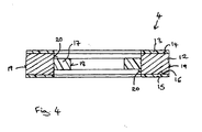
- Each annular sealing member 4, 5 is subtantially identical and one is illustrated in more detail in figure 4 .
- Each annular sealing member 4, 5 comprises a ring shaped plastically deformable core 12 of aluminium.
- a first layer 13 of rubber is positioned on, and fixedly attached to, the first major surface 14 of the aluminium core 12 and a second layer of rubber 15 is positioned on, and fixedly attached to, the second major surface 16 of the aluminium core 12.
- the annular sealing member 4, 5 can be thought of as a laminated washer comprising a layer of rubber on the major surfaces.
- the rubber layers 13, 15 are elastically deformable and provide a seal against fluid leaks when the respective layer is compressed between the head portion 23 of the bolt 3 and the body 2 and between the body 2 and a non-illustrated ports.
- the annular sealing member 4, 5 further comprises an inner annular portion 17 which protrudes inwardly from approximately the centre of the inner side face 18 of the aluminium core 12.
- the inner annular portion 17 provides a captive surface since the diameter of the inner annular portion 17 is slightly smaller than the outer diameter of the bolt 3.
- the inner annular portion 17 comprises rubber which is elastically deformable so that the annular sealing member 4, 5 may be detachedly maintained on the bolt 3 by axial compression of the annular sealing member 4, in particular, by axial compression of the inner annular portion 17.
- the rubber as well as the material of the core is selected for the application in which it is intended that the hydraulic coupling 1 will be used.
- the rubber coatings 13, 15 as well as the inner annular portion 17 may be ethylene propylene diene monomer rubber (EPDM).
- EPDM ethylene propylene diene monomer rubber
- a rubber suitable for use with brake oil may be used, for example a fluorocarbon rubber such as FKM.
- outer side faces 19 of the core 12 as well as the inner side faces 20 of the core 12 positioned adjacent the inner annular portion 17 are exposed and remained free from rubber in this embodiment.
- these surfaces are also provided with a layer of rubber.
- the first sealing member 4 is placed on the base portion 9 of the bolt 9, the bolt 3 is placed in the body 2 and the second sealing member 5 placed on the distal end of the bolt 3 so as to be positioned on the opposing side of the body 2.
- the distal end of the base portion 9 of the bolt 3 comprises a thread 21 in its outer surface 22.
- the bolt 3 and, therefore, the hydraulic coupling 1 is attached to a non-illustrated threaded port having a matching thread by applying a torque to the head 23 of the bolt 3.
- the elastically deformable rubber coating 13, 15 of the annular sealing member 4, 5 is compressed between the plastically deformable core 12 of the annular sealing member 4, 5 and the adjacent surface of the head 23 of the bolt 3 and the body 2 and between the body 2 and non-illustrated port, respectively.
- the elastically deformable rubber inner annular portion 17 is compressed against the outer surface 22 of the bolt 3.
- the combination of the inner rubber annular portion 17 and the rubber coating 13, 15 of the major surfaces provides a reliable seal preventing leaks of the fluid flowing though the hydraulic coupling 1. In use the fluid flows into passageway 7 and flows out of the distal end of the bolt 3 thus being redirected by approximately 90°.
- the annular sealing member 4 may have an overall thickness of 1 mm and the inner annular portion may have a thickness of 0.3 mm when the outer diameter of the sealing member 4 is 22 mm, the inner diameter of the core 12 is 14 mm and the inner diameter of the inner annular portion 17 is 13 mm.
- the sealing member may be manufactured by the following method. Firstly, a sheet of aluminium is provided and the two major surfaces of the sheet coated with rubber. A plurality of intermediate annular forms may be stamped from the coated sheet, each comprising an aluminium core 12 with a layer of rubber 13, 15 on its major surfaces. The outer side face 19 and inner side face 20 of the aluminium core 12 is free from rubber.
- a rubber annular member having an outer diameter approximately the same as the inner diameter of the aluminium core is provided and then attached to the inner side face of the aluminium core in approximately the centre of the inner side face.
- the rubber annular portion 17 of the annular sealing member 4 provides a captive surface of the annular sealing member 4.
- the rubber may be fixedly attached to the plastically deformable core 12 of the annular sealing member 4, 5 by a layer of adhesive or by directly fixing the rubber to the core 12.
Landscapes
- Engineering & Computer Science (AREA)
- General Engineering & Computer Science (AREA)
- Mechanical Engineering (AREA)
- Gasket Seals (AREA)
- Hydraulic Clutches, Magnetic Clutches, Fluid Clutches, And Fluid Joints (AREA)
Abstract
Description
- Hydraulic coupling, an annular sealing member for a hydraulic coupling and method for producing the annular sealing member
- The invention relates to a hydraulic coupling and an annular sealing member for a hydraulic coupling, in particular, for a banjo-type hydraulic coupling.
- Banjo-type hydraulic couplings may be used in brake systems and cooling systems of automobiles, for example, and are used when it is desired to supply fluid to a component through a 90° change of direction or other reorientation of the fluid flow.
- Banjo-type hydraulic couplings are so termed because of their shape. A banjo-type hydraulic coupling typically comprises a ring shaped body and a tube connected to an outer side face of the ring shaped body which is in flow communication with the opening of the ring giving rise to a substantially banjo-shaped assembly.
- A banjo-type hydraulic coupling also comprises a bolt with a hollow base portion and at least one radial fluid port. When the bolt is positioned in the through opening of the ring, the radial fluid port is in flow communication with the tube of the body thus allowing fluid entering the tube to be reorientated by 90° and flow out of the base of the bolt. In order to seal the body and bolt assembly, a washer is positioned on either side of the body and a specified torque applied to the assembly to provide the seal.
- Banjo-type couplings have the advantage that they are simple to assemble. Furthermore, they can be assembled from the front so that assembly can be affected with power tools. However, leaks in the coupling may still occur.
- In order to minimise potential leaks, it is known to improve the surface finish and provide tighter tolerances in the manufacture of the couplings. It is also known to use materials of a high tensile strength in order that higher torques can be applied in order to obtain the seal. However, further improvements to banjo-type hydraulic couplings are desired in order to further reduce the likelihood of leaks.
- It is, therefore, an object of the invention to provide a hydraulic coupling as well as a sealing member for a hydraulic coupling which provides a reliable seal and which can be cost-effectively manufactured.
- This object is solved by subject matter of the independent claims. Further improvements are the subject matter of the dependent claims.
- According to the invention, a hydraulic coupling comprises a body, a bolt and at least one annular sealing member. The body comprises an opening which extends through the body and a fluid passageway that intersects with and is in fluid communication with the opening. The bolt is adapted to be received in the opening through the body and comprises a base portion, an axial fluid passageway within the base portion which is open at one end and at least one radial fluid port in fluid communication with the axial fluid passageway. When the bolt is received in the opening though the body, the radial fluid port in the bolt is in fluid communication with the fluid passageway in the body. The at least one annular sealing member is adapted to be arranged between the bolt and the body. The sealing member comprises a plastically deformable core comprising a first major surface, a second major surface opposing the first major surface and an inner annular portion protruding inwardly from an inner side face of the plastically deformable core. A first rubber layer is positioned on the first major surface of the annular sealing member, a second rubber layer is positioned on the second major surface of the annular sealing member. The inner annular portion of the annular sealing member comprises rubber.
- According to the invention, the outer major surfaces of the annular sealing member each comprise a layer of rubber. The rubber may fixedly attached to the plastically deformable core of the annular sealing member. The rubber may be attached to the core by adhesive, for example. The major surfaces of the annular sealing member are in contact with the bolt or the body or the body and the port to which the coupling is fastened when the coupling is assembled and in use.
- The annular sealing member further comprises an inner annular portion which also comprises rubber and which provides the captive surface of the seal. Therefore, the outer major surfaces as well as the inner captive surface comprise a elastically deformable material in the form of rubber which is supported by a core of a plastically deformable material. The plastically deformable material may also be elastically deformable to a degree.
- The combination of the rubber outer major surfaces and rubber inner annular portion provides a sealing member for a banjo-type hydraulic coupling and a hydraulic coupling which is less prone to leaks.
- In an embodiment, the outer side face of the plastically deformable core remains free of rubber and in a further embodiment, the inner side face of the plastically deformable core adjacent the inner annular portion of the annular sealing member remains free of rubber.
- The above embodiments in which the outer side face of the plastically deformable core and/or the inner side face of the plastically deformable core adjacent the inner annular portion remains free of rubber have the advantage that the annular sealing member can be manufactured by the following simple method.
- The sealing member may be manufactured by providing a sheet of the plastically deformable core material and attaching a rubber coating on each of the two major surfaces of the sheet thus forming a laminate. The annular member may then be stamped from this laminate and a ring-shaped rubber portion attached to the inner side face of the ring to provide the inner annular portion of the sealing member.
- In an alternative embodiment, all of the outer surfaces of the plastically deformable core are coated in rubber.
- An outer surface of the base portion of the bolt may comprise a threaded portion. This enables the bolt and, therefore, the hydraulic coupling to be attached to a threaded port. The annular sealing member is compressed between the head of the bolt and the body or between the body and the port to which the coupling is fastened by applying torque to the head of the bolt.
- In a further embodiment of the invention, the inner diameter of the inner annular member is selected such that the annular sealing member is detachedly maintainable on the bolt by axial compression. The inner diameter of the inner annular member is, therefore, slightly smaller than the outer diameter of the bolt of the hydraulic coupling. In order to place the annular sealing member on the bolt, the rubber of the inner annular portion is elastically deformed so that the sealing member is detachedly maintainable on the bolt by axial compression of at least the rubber inner annular portion.
- The plastically deformable core may comprise plastic, metal or an alloy. In particular embodiments of the invention, the plastically deformable core comprises steel or aluminium.
- The type of rubber used may depend on the application in which the hydraulic coupling is to be used. For cooling systems including water, the rubber may be one of ethylene propylene diene monomer rubber (EPDM), or hydrogenated nitrile butadiene rubber (HNBR) or nitrile-butadiene rubber (NBR). For brake systems including oil, the rubber may be a fluorocarbon rubber such as FKM or FPM.
- The hydraulic coupling may include two sealing members which are substantially the same. In use, one sealing member is positioned on the bolt on each side of the body. Therefore, one sealing member is positioned between the head of the bolt and the body and the second sealing member is positioned between the body and the port to which the coupling is attached.
- Embodiments will now be explained with reference to the accompanying drawings.
- Figure 1
- illustrates a side view of a banjo-type hydraulic coupling according to the invention,
- Figure 2
- illustrates a partial cross-sectional view of the hydraulic coupling of
figure 1 , - Figure 3
- illustrates a plan view of the body of the hydraulic coupling of
figures 1 and 2 , - Figure 4
- illustrates a cross-sectional view of the sealing member of the hydraulic coupling of
figures 1 to 3 . -
Figures 1 to 3 illustrate an assembled a banjo-type hydraulic coupling 1 according to the invention. The hydraulic coupling 1 comprises abody 2, abolt 3 and twoannular sealing members 4, 5. -
Figure 1 illustrates a side view of the assembled hydraulic coupling 1 andfigure 2 illustrates a partial cross-sectional side view of the assembled hydraulic coupling 1 offigure 1 . A plan view of thebody 2 of the hydraulic coupling 1 is illustrated infigure 3 . - The
body 2 comprises anopening 6 which extends through thebody 2 and afluid passageway 7 which intersects with and is in fluid communication with theopening 6. From the plan view offigure 3 , it can be seen that in the body has a substantially cylindrical portion 8 through which theopening 6 extends and that thefluid passageway 7 extends from an outer side face of the cylindrical portion 8. The longitudinal axis of thefluid passageway 7 lies at approximately 90° to the longitudinal axis of theopening 6 of thebody 2 in this embodiment. - The
bolt 3 of the hydraulic coupling 1 is adapted to be received in theopening 6 of thebody 2. The outer diameter of thebolt 3 is slightly smaller than the inner diameter of theopening 6 of thebody 2. The bolt has a base portion 9 and ahead portion 23 which is laterally larger than the base portion 9 and which has a generally hexagonal shape. Thebolt 3 further comprises anaxial fluid passageway 10 within the base portion 9 which is open at the distal end of the base portion 9. - The bolt further comprises a plurality of radial fluid ports 11, of which one is illustrated in the cross-sectional view of
figure 2 , which are in flow communication with theaxial fluid passageway 10 of the base portion 9. The radial fluid ports 11 extend in a direction which lies at approximately 90° to the axis of thefluid passageway 10 of the bolt. - The hydraulic coupling 1 is assembled so that one of the
annular sealing members 4, 5 is positioned on either side of thebody 2 and so that thebolt 3 is received in theopening 6 of thebody 2. Therefore, one sealing member 4 is positioned between thehead portion 23 of thebolt 3 and thebody 2 and thesecond sealing member 5 is positioned on the opposing side of thebody 2. Thebolt 3 extends generally transversely to thefluid passageway 7 of thebody 2. - When assembled the radial fluid ports 11 of the
bolt 3 are in flow communication with thepassageway 7 of thebody 2. Therefore, a fluid entering thepassageway 7 is redirected through 90° by flowing through the radial fluid ports 11 and axial passageway 9 of thebolt 3. The fluid may also flow through the coupling in the reverse direction. - The
annular sealing members 4, 5 each have an inner diameter which is slightly smaller than the outer diameter of thebolt 3. Therefore, theannular sealing members 4, 5 are detachedly maintained on thebolt 3 by axial compression. - The
annular sealing members 4, 5 are subtantially identical and one is illustrated in more detail infigure 4 . Eachannular sealing member 4, 5 comprises a ring shaped plasticallydeformable core 12 of aluminium. A first layer 13 of rubber is positioned on, and fixedly attached to, the firstmajor surface 14 of thealuminium core 12 and a second layer of rubber 15 is positioned on, and fixedly attached to, the secondmajor surface 16 of thealuminium core 12. - The
annular sealing member 4, 5 can be thought of as a laminated washer comprising a layer of rubber on the major surfaces. The rubber layers 13, 15 are elastically deformable and provide a seal against fluid leaks when the respective layer is compressed between thehead portion 23 of thebolt 3 and thebody 2 and between thebody 2 and a non-illustrated ports. - The
annular sealing member 4, 5 further comprises an innerannular portion 17 which protrudes inwardly from approximately the centre of the inner side face 18 of thealuminium core 12. The innerannular portion 17 provides a captive surface since the diameter of the innerannular portion 17 is slightly smaller than the outer diameter of thebolt 3. The innerannular portion 17 comprises rubber which is elastically deformable so that theannular sealing member 4, 5 may be detachedly maintained on thebolt 3 by axial compression of the annular sealing member 4, in particular, by axial compression of the innerannular portion 17. - The rubber as well as the material of the core is selected for the application in which it is intended that the hydraulic coupling 1 will be used. If the hydraulic coupling is to be used in a water cooling system, the rubber coatings 13, 15 as well as the inner
annular portion 17 may be ethylene propylene diene monomer rubber (EPDM). If the hydraulic coupling 1 is to be used in an automobile brake system, a rubber suitable for use with brake oil may be used, for example a fluorocarbon rubber such as FKM. - The outer side faces 19 of the core 12 as well as the inner side faces 20 of the core 12 positioned adjacent the inner
annular portion 17 are exposed and remained free from rubber in this embodiment. In a further embodiment is not illustrated in the figures, these surfaces are also provided with a layer of rubber. - To use the hydraulic coupling 1, the first sealing member 4 is placed on the base portion 9 of the bolt 9, the
bolt 3 is placed in thebody 2 and thesecond sealing member 5 placed on the distal end of thebolt 3 so as to be positioned on the opposing side of thebody 2. - The distal end of the base portion 9 of the
bolt 3 comprises athread 21 in itsouter surface 22. Thebolt 3 and, therefore, the hydraulic coupling 1 is attached to a non-illustrated threaded port having a matching thread by applying a torque to thehead 23 of thebolt 3. - The elastically deformable rubber coating 13, 15 of the
annular sealing member 4, 5 is compressed between the plasticallydeformable core 12 of theannular sealing member 4, 5 and the adjacent surface of thehead 23 of thebolt 3 and thebody 2 and between thebody 2 and non-illustrated port, respectively. At the same time, the elastically deformable rubber innerannular portion 17 is compressed against theouter surface 22 of thebolt 3. The combination of the inner rubberannular portion 17 and the rubber coating 13, 15 of the major surfaces provides a reliable seal preventing leaks of the fluid flowing though the hydraulic coupling 1. In use the fluid flows intopassageway 7 and flows out of the distal end of thebolt 3 thus being redirected by approximately 90°. - The annular sealing member 4 may have an overall thickness of 1 mm and the inner annular portion may have a thickness of 0.3 mm when the outer diameter of the sealing member 4 is 22 mm, the inner diameter of the
core 12 is 14 mm and the inner diameter of the innerannular portion 17 is 13 mm. - The sealing member may be manufactured by the following method. Firstly, a sheet of aluminium is provided and the two major surfaces of the sheet coated with rubber. A plurality of intermediate annular forms may be stamped from the coated sheet, each comprising an
aluminium core 12 with a layer of rubber 13, 15 on its major surfaces. Theouter side face 19 and inner side face 20 of thealuminium core 12 is free from rubber. - A rubber annular member having an outer diameter approximately the same as the inner diameter of the aluminium core is provided and then attached to the inner side face of the aluminium core in approximately the centre of the inner side face. The rubber
annular portion 17 of the annular sealing member 4 provides a captive surface of the annular sealing member 4. - The rubber may be fixedly attached to the plastically
deformable core 12 of theannular sealing member 4, 5 by a layer of adhesive or by directly fixing the rubber to thecore 12. -
- 1
- hydraulic coupling
- 2
- body
- 3
- bolt
- 4
- first annular sealing member
- 5
- second annular sealing member
- 6
- opening
- 7
- fluid passageway
- 8
- cylindrical portion of body
- 9
- base portion of bolt
- 10
- axial fluid passageway of bolt
- 11
- radial fluid passageway of bolt
- 12
- aluminium core
- 13
- first layer of rubber
- 14
- first major surface
- 15
- second layer of rubber
- 16
- second major surface
- 17
- inner annular portion
- 18
- inner side face of core
- 19
- outer side face of core
- 20
- inner side face of core
- 21
- thread
- 22
- outer surface
- 23
- head portion of bolt
Claims (22)
a first rubber layer (13) is positioned on the first major surface (14), a second rubber layer (15) is positioned on the second major surface (16) and the inner annular portion (17) comprises rubber.
characterized in that
the outer side face (20) of the plastically deformable (12) core remains free of rubber.
characterized in that
the inner side face (20) of the plastically deformable core (12) adjacent the inner annular portion (17) remains free of rubber.
characterized in that
the outer side face (19) and the inner side face (20) of the plastically deformable core (12) adjacent the inner annular portion (17) comprise a rubber coating.
characterized in that
the inner diameter of the inner annular member (17) is selected such that the sealing member (4, 5) is detachedly maintainable on the bolt (3) by axial compression.
characterized in that
the plastically deformable core (12) comprises plastic.
characterized in that
the plastically deformable core (12) comprises a metal or an alloy.
characterized in that
the plastically deformable core (12) comprises steel or aluminium.
characterized in that
the rubber is fluorocarbon rubber.
characterized in that
the rubber is ethylene propylene diene monomer rubber, or hydrogenated nitrile butadiene rubber or nitrile-butadiene rubber.
characterized in that
a sealing member (4, 5) is arranged on opposing sides of the body (2).
characterized in that
the hydraulic coupling (1) is a banjo-type hydraulic coupling.
characterized in that
a first rubber layer (13) is positioned on the first major surface (14), a second rubber layer (15) is positioned on the second major surface (16) and the inner annular portion (17) comprises rubber.
characterized in that
the outer side face (20) of the plastically deformable core (12) remains free of rubber.
characterized in that
the inner side face (20) of the plastically deformable core (12) adjacent the inner annular portion (17) remains free of rubber.
characterized in that
the inner diameter of the inner annular member (17) is selected such that the sealing member (4, 5) is detachedly maintainable on the bolt (3) by axial compression.
characterized in that
the plastically deformable core (12) comprises plastic.
characterized in that
the plastically deformable core (12) comprises a metal or an alloy.
characterized in that
the plastically deformable core (12) comprises steel or aluminium.
characterized in that
the rubber is fluorocarbon rubber.
characterized in that
the rubber is ethylene propylene diene monomer rubber, or hydrogenated nitrile butadiene rubber or nitrile-butadiene rubber.
Priority Applications (2)
| Application Number | Priority Date | Filing Date | Title |
|---|---|---|---|
| AT08001392T ATE536513T1 (en) | 2008-01-25 | 2008-01-25 | HYDRAULIC CLUTCH |
| EP08001392A EP2083204B1 (en) | 2008-01-25 | 2008-01-25 | Hydraulic coupling |
Applications Claiming Priority (1)
| Application Number | Priority Date | Filing Date | Title |
|---|---|---|---|
| EP08001392A EP2083204B1 (en) | 2008-01-25 | 2008-01-25 | Hydraulic coupling |
Publications (2)
| Publication Number | Publication Date |
|---|---|
| EP2083204A1 true EP2083204A1 (en) | 2009-07-29 |
| EP2083204B1 EP2083204B1 (en) | 2011-12-07 |
Family
ID=39539655
Family Applications (1)
| Application Number | Title | Priority Date | Filing Date |
|---|---|---|---|
| EP08001392A Not-in-force EP2083204B1 (en) | 2008-01-25 | 2008-01-25 | Hydraulic coupling |
Country Status (2)
| Country | Link |
|---|---|
| EP (1) | EP2083204B1 (en) |
| AT (1) | ATE536513T1 (en) |
Cited By (1)
| Publication number | Priority date | Publication date | Assignee | Title |
|---|---|---|---|---|
| US8511717B2 (en) | 2011-06-30 | 2013-08-20 | Harley-Davidson Motor Company Group, LLC | Poka-yoke for a set of hydraulic fittings |
Families Citing this family (1)
| Publication number | Priority date | Publication date | Assignee | Title |
|---|---|---|---|---|
| CN106499802A (en) * | 2016-12-19 | 2017-03-15 | 中车长春轨道客车股份有限公司 | Sensor rubber gasket and the gear-box with the sensor rubber gasket |
Citations (8)
| Publication number | Priority date | Publication date | Assignee | Title |
|---|---|---|---|---|
| GB883464A (en) * | 1958-12-30 | 1961-11-29 | Prec Rubbers Ltd | Improvements relating to sealing washers or gaskets |
| US3124366A (en) * | 1964-03-10 | Ring-type gasket | ||
| EP0251516A1 (en) * | 1986-06-27 | 1988-01-07 | Parker Hannifin Corporation | Seal assembly for a fastener |
| DE3802090A1 (en) * | 1988-01-26 | 1989-08-03 | Goetze Ag | Metallic flat gasket material |
| EP0339364A2 (en) * | 1988-04-19 | 1989-11-02 | Hoechst Aktiengesellschaft | Flat packing |
| US5407214A (en) * | 1991-12-31 | 1995-04-18 | Lew; Hyok S. | Fire barrier gasket seal |
| DE29715844U1 (en) * | 1997-09-03 | 1997-10-23 | Böllhoff GmbH Verbindungs- und Montagetechnik, 33649 Bielefeld | Sealing washer |
| EP1843072A2 (en) * | 2006-04-05 | 2007-10-10 | Doowon Climate Control Co., Ltd | Pipe connecting structure |
-
2008
- 2008-01-25 EP EP08001392A patent/EP2083204B1/en not_active Not-in-force
- 2008-01-25 AT AT08001392T patent/ATE536513T1/en active
Patent Citations (8)
| Publication number | Priority date | Publication date | Assignee | Title |
|---|---|---|---|---|
| US3124366A (en) * | 1964-03-10 | Ring-type gasket | ||
| GB883464A (en) * | 1958-12-30 | 1961-11-29 | Prec Rubbers Ltd | Improvements relating to sealing washers or gaskets |
| EP0251516A1 (en) * | 1986-06-27 | 1988-01-07 | Parker Hannifin Corporation | Seal assembly for a fastener |
| DE3802090A1 (en) * | 1988-01-26 | 1989-08-03 | Goetze Ag | Metallic flat gasket material |
| EP0339364A2 (en) * | 1988-04-19 | 1989-11-02 | Hoechst Aktiengesellschaft | Flat packing |
| US5407214A (en) * | 1991-12-31 | 1995-04-18 | Lew; Hyok S. | Fire barrier gasket seal |
| DE29715844U1 (en) * | 1997-09-03 | 1997-10-23 | Böllhoff GmbH Verbindungs- und Montagetechnik, 33649 Bielefeld | Sealing washer |
| EP1843072A2 (en) * | 2006-04-05 | 2007-10-10 | Doowon Climate Control Co., Ltd | Pipe connecting structure |
Cited By (1)
| Publication number | Priority date | Publication date | Assignee | Title |
|---|---|---|---|---|
| US8511717B2 (en) | 2011-06-30 | 2013-08-20 | Harley-Davidson Motor Company Group, LLC | Poka-yoke for a set of hydraulic fittings |
Also Published As
| Publication number | Publication date |
|---|---|
| ATE536513T1 (en) | 2011-12-15 |
| EP2083204B1 (en) | 2011-12-07 |
Similar Documents
| Publication | Publication Date | Title |
|---|---|---|
| EP3717788B1 (en) | Two-piece blind fastener | |
| EP2564104B1 (en) | High-pressure tube fittings and end-face preparation tools | |
| CN101608722B (en) | Pipe connection device for attaching pipes | |
| EP1992860B1 (en) | Non-serviceable fluid coupling | |
| US7549679B2 (en) | Pipe fitting with compression of seal structure | |
| JP2010180875A (en) | Improvement in high pressure fuel piping fitting | |
| GB2503880A (en) | Insert for Pipes | |
| US6375232B1 (en) | Bi-metallic union fitting for use in threaded ports | |
| US20070222159A1 (en) | Composite seal and coupling | |
| US20200256490A1 (en) | Enhanced hose fitting and method of assembly | |
| US7686352B2 (en) | Tubing for a plumbing connection | |
| EP2083204B1 (en) | Hydraulic coupling | |
| JP5707093B2 (en) | Pipe connection structure and hose fittings | |
| JP4901393B2 (en) | Detachment prevention structure for pipe joints | |
| CA2610891A1 (en) | Tubular crimp connection and method of forming | |
| WO2018150365A1 (en) | Hydraulic component for hydraulic systems, in particular for braking systems or hydraulic clutch drives, in the automotive sector | |
| US7654189B2 (en) | Heavy duty cylinder | |
| CN211083164U (en) | Pipe joint, engine assembly and vehicle | |
| CN115234725B (en) | A sealing flange joint for R744 refrigerant high-pressure air conditioning pipeline | |
| JP2017211010A (en) | Hydraulic piping hose, brake hose, and hose mouthpiece | |
| JP2007192274A (en) | Pipe fitting | |
| CN218494180U (en) | Bolt connection structure with sealing function | |
| US9255655B2 (en) | Fluid coupling assembly | |
| CN110848481A (en) | Pipe joint, engine assembly and vehicle | |
| JP2017211009A (en) | Hydraulic piping hose, brake hose, and hose mouthpiece |
Legal Events
| Date | Code | Title | Description |
|---|---|---|---|
| PUAI | Public reference made under article 153(3) epc to a published international application that has entered the european phase |
Free format text: ORIGINAL CODE: 0009012 |
|
| AK | Designated contracting states |
Kind code of ref document: A1 Designated state(s): AT BE BG CH CY CZ DE DK EE ES FI FR GB GR HR HU IE IS IT LI LT LU LV MC MT NL NO PL PT RO SE SI SK TR |
|
| AX | Request for extension of the european patent |
Extension state: AL BA MK RS |
|
| 17P | Request for examination filed |
Effective date: 20100129 |
|
| 17Q | First examination report despatched |
Effective date: 20100223 |
|
| AKX | Designation fees paid |
Designated state(s): AT BE BG CH CY CZ DE DK EE ES FI FR GB GR HR HU IE IS IT LI LT LU LV MC MT NL NO PL PT RO SE SI SK TR |
|
| RAP1 | Party data changed (applicant data changed or rights of an application transferred) |
Owner name: GM GLOBAL TECHNOLOGY OPERATIONS LLC |
|
| GRAP | Despatch of communication of intention to grant a patent |
Free format text: ORIGINAL CODE: EPIDOSNIGR1 |
|
| GRAS | Grant fee paid |
Free format text: ORIGINAL CODE: EPIDOSNIGR3 |
|
| GRAA | (expected) grant |
Free format text: ORIGINAL CODE: 0009210 |
|
| AK | Designated contracting states |
Kind code of ref document: B1 Designated state(s): AT BE BG CH CY CZ DE DK EE ES FI FR GB GR HR HU IE IS IT LI LT LU LV MC MT NL NO PL PT RO SE SI SK TR |
|
| REG | Reference to a national code |
Ref country code: GB Ref legal event code: FG4D |
|
| REG | Reference to a national code |
Ref country code: CH Ref legal event code: EP |
|
| REG | Reference to a national code |
Ref country code: IE Ref legal event code: FG4D |
|
| REG | Reference to a national code |
Ref country code: DE Ref legal event code: R096 Ref document number: 602008011797 Country of ref document: DE Effective date: 20120209 |
|
| REG | Reference to a national code |
Ref country code: NL Ref legal event code: VDEP Effective date: 20111207 |
|
| PG25 | Lapsed in a contracting state [announced via postgrant information from national office to epo] |
Ref country code: LT Free format text: LAPSE BECAUSE OF FAILURE TO SUBMIT A TRANSLATION OF THE DESCRIPTION OR TO PAY THE FEE WITHIN THE PRESCRIBED TIME-LIMIT Effective date: 20111207 Ref country code: NO Free format text: LAPSE BECAUSE OF FAILURE TO SUBMIT A TRANSLATION OF THE DESCRIPTION OR TO PAY THE FEE WITHIN THE PRESCRIBED TIME-LIMIT Effective date: 20120307 |
|
| LTIE | Lt: invalidation of european patent or patent extension |
Effective date: 20111207 |
|
| PG25 | Lapsed in a contracting state [announced via postgrant information from national office to epo] |
Ref country code: HR Free format text: LAPSE BECAUSE OF FAILURE TO SUBMIT A TRANSLATION OF THE DESCRIPTION OR TO PAY THE FEE WITHIN THE PRESCRIBED TIME-LIMIT Effective date: 20111207 Ref country code: LV Free format text: LAPSE BECAUSE OF FAILURE TO SUBMIT A TRANSLATION OF THE DESCRIPTION OR TO PAY THE FEE WITHIN THE PRESCRIBED TIME-LIMIT Effective date: 20111207 Ref country code: NL Free format text: LAPSE BECAUSE OF FAILURE TO SUBMIT A TRANSLATION OF THE DESCRIPTION OR TO PAY THE FEE WITHIN THE PRESCRIBED TIME-LIMIT Effective date: 20111207 Ref country code: SI Free format text: LAPSE BECAUSE OF FAILURE TO SUBMIT A TRANSLATION OF THE DESCRIPTION OR TO PAY THE FEE WITHIN THE PRESCRIBED TIME-LIMIT Effective date: 20111207 Ref country code: GR Free format text: LAPSE BECAUSE OF FAILURE TO SUBMIT A TRANSLATION OF THE DESCRIPTION OR TO PAY THE FEE WITHIN THE PRESCRIBED TIME-LIMIT Effective date: 20120308 Ref country code: SE Free format text: LAPSE BECAUSE OF FAILURE TO SUBMIT A TRANSLATION OF THE DESCRIPTION OR TO PAY THE FEE WITHIN THE PRESCRIBED TIME-LIMIT Effective date: 20111207 |
|
| PG25 | Lapsed in a contracting state [announced via postgrant information from national office to epo] |
Ref country code: BE Free format text: LAPSE BECAUSE OF FAILURE TO SUBMIT A TRANSLATION OF THE DESCRIPTION OR TO PAY THE FEE WITHIN THE PRESCRIBED TIME-LIMIT Effective date: 20111207 Ref country code: CY Free format text: LAPSE BECAUSE OF FAILURE TO SUBMIT A TRANSLATION OF THE DESCRIPTION OR TO PAY THE FEE WITHIN THE PRESCRIBED TIME-LIMIT Effective date: 20111207 |
|
| PG25 | Lapsed in a contracting state [announced via postgrant information from national office to epo] |
Ref country code: SK Free format text: LAPSE BECAUSE OF FAILURE TO SUBMIT A TRANSLATION OF THE DESCRIPTION OR TO PAY THE FEE WITHIN THE PRESCRIBED TIME-LIMIT Effective date: 20111207 Ref country code: BG Free format text: LAPSE BECAUSE OF FAILURE TO SUBMIT A TRANSLATION OF THE DESCRIPTION OR TO PAY THE FEE WITHIN THE PRESCRIBED TIME-LIMIT Effective date: 20120307 Ref country code: IS Free format text: LAPSE BECAUSE OF FAILURE TO SUBMIT A TRANSLATION OF THE DESCRIPTION OR TO PAY THE FEE WITHIN THE PRESCRIBED TIME-LIMIT Effective date: 20120407 Ref country code: CZ Free format text: LAPSE BECAUSE OF FAILURE TO SUBMIT A TRANSLATION OF THE DESCRIPTION OR TO PAY THE FEE WITHIN THE PRESCRIBED TIME-LIMIT Effective date: 20111207 Ref country code: EE Free format text: LAPSE BECAUSE OF FAILURE TO SUBMIT A TRANSLATION OF THE DESCRIPTION OR TO PAY THE FEE WITHIN THE PRESCRIBED TIME-LIMIT Effective date: 20111207 |
|
| PG25 | Lapsed in a contracting state [announced via postgrant information from national office to epo] |
Ref country code: MC Free format text: LAPSE BECAUSE OF NON-PAYMENT OF DUE FEES Effective date: 20120131 Ref country code: RO Free format text: LAPSE BECAUSE OF FAILURE TO SUBMIT A TRANSLATION OF THE DESCRIPTION OR TO PAY THE FEE WITHIN THE PRESCRIBED TIME-LIMIT Effective date: 20111207 Ref country code: PT Free format text: LAPSE BECAUSE OF FAILURE TO SUBMIT A TRANSLATION OF THE DESCRIPTION OR TO PAY THE FEE WITHIN THE PRESCRIBED TIME-LIMIT Effective date: 20120409 Ref country code: PL Free format text: LAPSE BECAUSE OF FAILURE TO SUBMIT A TRANSLATION OF THE DESCRIPTION OR TO PAY THE FEE WITHIN THE PRESCRIBED TIME-LIMIT Effective date: 20111207 |
|
| REG | Reference to a national code |
Ref country code: CH Ref legal event code: PL |
|
| REG | Reference to a national code |
Ref country code: AT Ref legal event code: MK05 Ref document number: 536513 Country of ref document: AT Kind code of ref document: T Effective date: 20111207 |
|
| PLBE | No opposition filed within time limit |
Free format text: ORIGINAL CODE: 0009261 |
|
| STAA | Information on the status of an ep patent application or granted ep patent |
Free format text: STATUS: NO OPPOSITION FILED WITHIN TIME LIMIT |
|
| REG | Reference to a national code |
Ref country code: IE Ref legal event code: MM4A |
|
| PG25 | Lapsed in a contracting state [announced via postgrant information from national office to epo] |
Ref country code: CH Free format text: LAPSE BECAUSE OF NON-PAYMENT OF DUE FEES Effective date: 20120131 Ref country code: DK Free format text: LAPSE BECAUSE OF FAILURE TO SUBMIT A TRANSLATION OF THE DESCRIPTION OR TO PAY THE FEE WITHIN THE PRESCRIBED TIME-LIMIT Effective date: 20111207 Ref country code: LI Free format text: LAPSE BECAUSE OF NON-PAYMENT OF DUE FEES Effective date: 20120131 |
|
| 26N | No opposition filed |
Effective date: 20120910 |
|
| PG25 | Lapsed in a contracting state [announced via postgrant information from national office to epo] |
Ref country code: IT Free format text: LAPSE BECAUSE OF FAILURE TO SUBMIT A TRANSLATION OF THE DESCRIPTION OR TO PAY THE FEE WITHIN THE PRESCRIBED TIME-LIMIT Effective date: 20111207 |
|
| REG | Reference to a national code |
Ref country code: DE Ref legal event code: R097 Ref document number: 602008011797 Country of ref document: DE Effective date: 20120910 |
|
| PG25 | Lapsed in a contracting state [announced via postgrant information from national office to epo] |
Ref country code: IE Free format text: LAPSE BECAUSE OF NON-PAYMENT OF DUE FEES Effective date: 20120125 Ref country code: AT Free format text: LAPSE BECAUSE OF FAILURE TO SUBMIT A TRANSLATION OF THE DESCRIPTION OR TO PAY THE FEE WITHIN THE PRESCRIBED TIME-LIMIT Effective date: 20111207 |
|
| PG25 | Lapsed in a contracting state [announced via postgrant information from national office to epo] |
Ref country code: ES Free format text: LAPSE BECAUSE OF FAILURE TO SUBMIT A TRANSLATION OF THE DESCRIPTION OR TO PAY THE FEE WITHIN THE PRESCRIBED TIME-LIMIT Effective date: 20120318 |
|
| PG25 | Lapsed in a contracting state [announced via postgrant information from national office to epo] |
Ref country code: FI Free format text: LAPSE BECAUSE OF FAILURE TO SUBMIT A TRANSLATION OF THE DESCRIPTION OR TO PAY THE FEE WITHIN THE PRESCRIBED TIME-LIMIT Effective date: 20111207 |
|
| PG25 | Lapsed in a contracting state [announced via postgrant information from national office to epo] |
Ref country code: MT Free format text: LAPSE BECAUSE OF FAILURE TO SUBMIT A TRANSLATION OF THE DESCRIPTION OR TO PAY THE FEE WITHIN THE PRESCRIBED TIME-LIMIT Effective date: 20111207 |
|
| PG25 | Lapsed in a contracting state [announced via postgrant information from national office to epo] |
Ref country code: TR Free format text: LAPSE BECAUSE OF FAILURE TO SUBMIT A TRANSLATION OF THE DESCRIPTION OR TO PAY THE FEE WITHIN THE PRESCRIBED TIME-LIMIT Effective date: 20111207 |
|
| PG25 | Lapsed in a contracting state [announced via postgrant information from national office to epo] |
Ref country code: LU Free format text: LAPSE BECAUSE OF NON-PAYMENT OF DUE FEES Effective date: 20120125 |
|
| PG25 | Lapsed in a contracting state [announced via postgrant information from national office to epo] |
Ref country code: HU Free format text: LAPSE BECAUSE OF FAILURE TO SUBMIT A TRANSLATION OF THE DESCRIPTION OR TO PAY THE FEE WITHIN THE PRESCRIBED TIME-LIMIT Effective date: 20080125 |
|
| REG | Reference to a national code |
Ref country code: FR Ref legal event code: PLFP Year of fee payment: 9 |
|
| PGFP | Annual fee paid to national office [announced via postgrant information from national office to epo] |
Ref country code: FR Payment date: 20151208 Year of fee payment: 9 |
|
| PGFP | Annual fee paid to national office [announced via postgrant information from national office to epo] |
Ref country code: DE Payment date: 20160119 Year of fee payment: 9 |
|
| PGFP | Annual fee paid to national office [announced via postgrant information from national office to epo] |
Ref country code: GB Payment date: 20160120 Year of fee payment: 9 |
|
| REG | Reference to a national code |
Ref country code: DE Ref legal event code: R119 Ref document number: 602008011797 Country of ref document: DE |
|
| GBPC | Gb: european patent ceased through non-payment of renewal fee |
Effective date: 20170125 |
|
| REG | Reference to a national code |
Ref country code: FR Ref legal event code: ST Effective date: 20170929 |
|
| PG25 | Lapsed in a contracting state [announced via postgrant information from national office to epo] |
Ref country code: FR Free format text: LAPSE BECAUSE OF NON-PAYMENT OF DUE FEES Effective date: 20170131 |
|
| PG25 | Lapsed in a contracting state [announced via postgrant information from national office to epo] |
Ref country code: DE Free format text: LAPSE BECAUSE OF NON-PAYMENT OF DUE FEES Effective date: 20170801 Ref country code: GB Free format text: LAPSE BECAUSE OF NON-PAYMENT OF DUE FEES Effective date: 20170125 |