EP2083181A1 - Developments in or relating to the balancing of a rotating assembly - Google Patents
Developments in or relating to the balancing of a rotating assembly Download PDFInfo
- Publication number
- EP2083181A1 EP2083181A1 EP08019252A EP08019252A EP2083181A1 EP 2083181 A1 EP2083181 A1 EP 2083181A1 EP 08019252 A EP08019252 A EP 08019252A EP 08019252 A EP08019252 A EP 08019252A EP 2083181 A1 EP2083181 A1 EP 2083181A1
- Authority
- EP
- European Patent Office
- Prior art keywords
- axis
- geometric axis
- rotating assembly
- rotating
- rotation
- Prior art date
- Legal status (The legal status is an assumption and is not a legal conclusion. Google has not performed a legal analysis and makes no representation as to the accuracy of the status listed.)
- Granted
Links
- 238000011161 development Methods 0.000 title description 2
- 230000018109 developmental process Effects 0.000 title description 2
- 238000000034 method Methods 0.000 claims description 11
- 230000003068 static effect Effects 0.000 description 4
- 238000003754 machining Methods 0.000 description 2
- 230000000712 assembly Effects 0.000 description 1
- 238000000429 assembly Methods 0.000 description 1
- 238000010586 diagram Methods 0.000 description 1
- 238000005516 engineering process Methods 0.000 description 1
- 238000002955 isolation Methods 0.000 description 1
Images




Classifications
-
- F—MECHANICAL ENGINEERING; LIGHTING; HEATING; WEAPONS; BLASTING
- F16—ENGINEERING ELEMENTS AND UNITS; GENERAL MEASURES FOR PRODUCING AND MAINTAINING EFFECTIVE FUNCTIONING OF MACHINES OR INSTALLATIONS; THERMAL INSULATION IN GENERAL
- F16C—SHAFTS; FLEXIBLE SHAFTS; ELEMENTS OR CRANKSHAFT MECHANISMS; ROTARY BODIES OTHER THAN GEARING ELEMENTS; BEARINGS
- F16C3/00—Shafts; Axles; Cranks; Eccentrics
- F16C3/04—Crankshafts, eccentric-shafts; Cranks, eccentrics
- F16C3/20—Shape of crankshafts or eccentric-shafts having regard to balancing
-
- F—MECHANICAL ENGINEERING; LIGHTING; HEATING; WEAPONS; BLASTING
- F16—ENGINEERING ELEMENTS AND UNITS; GENERAL MEASURES FOR PRODUCING AND MAINTAINING EFFECTIVE FUNCTIONING OF MACHINES OR INSTALLATIONS; THERMAL INSULATION IN GENERAL
- F16D—COUPLINGS FOR TRANSMITTING ROTATION; CLUTCHES; BRAKES
- F16D3/00—Yielding couplings, i.e. with means permitting movement between the connected parts during the drive
- F16D3/02—Yielding couplings, i.e. with means permitting movement between the connected parts during the drive adapted to specific functions
- F16D3/04—Yielding couplings, i.e. with means permitting movement between the connected parts during the drive adapted to specific functions specially adapted to allow radial displacement, e.g. Oldham couplings
-
- F—MECHANICAL ENGINEERING; LIGHTING; HEATING; WEAPONS; BLASTING
- F16—ENGINEERING ELEMENTS AND UNITS; GENERAL MEASURES FOR PRODUCING AND MAINTAINING EFFECTIVE FUNCTIONING OF MACHINES OR INSTALLATIONS; THERMAL INSULATION IN GENERAL
- F16D—COUPLINGS FOR TRANSMITTING ROTATION; CLUTCHES; BRAKES
- F16D3/00—Yielding couplings, i.e. with means permitting movement between the connected parts during the drive
- F16D3/02—Yielding couplings, i.e. with means permitting movement between the connected parts during the drive adapted to specific functions
- F16D3/06—Yielding couplings, i.e. with means permitting movement between the connected parts during the drive adapted to specific functions specially adapted to allow axial displacement
-
- F—MECHANICAL ENGINEERING; LIGHTING; HEATING; WEAPONS; BLASTING
- F16—ENGINEERING ELEMENTS AND UNITS; GENERAL MEASURES FOR PRODUCING AND MAINTAINING EFFECTIVE FUNCTIONING OF MACHINES OR INSTALLATIONS; THERMAL INSULATION IN GENERAL
- F16F—SPRINGS; SHOCK-ABSORBERS; MEANS FOR DAMPING VIBRATION
- F16F15/00—Suppression of vibrations in systems; Means or arrangements for avoiding or reducing out-of-balance forces, e.g. due to motion
- F16F15/32—Correcting- or balancing-weights or equivalent means for balancing rotating bodies, e.g. vehicle wheels
- F16F15/322—Correcting- or balancing-weights or equivalent means for balancing rotating bodies, e.g. vehicle wheels the rotating body being a shaft
Definitions
- the present invention relates to a rotating arrangement comprising a rotating assembly mounted on a bearing, for example a rotor assembly in a gas turbine, and more particularly to developments in or relating to the balancing of such a rotating assembly.
- Rotating components can be balanced by re-distributing the mass of the component so that the centre of mass of the component coincides with the geometric axis of rotation of the component.
- a common method of re-distributing the mass of the component, in order to balance the component, is to add material to the component or to remove material from the component.
- each of these methods carries an associated weight penalty, which can be particularly critical in, for example, aerospace applications.
- this weight penalty arises from the fact that the component must initially be provided with additional, sacrificial material that can be removed for balancing purposes, but which almost inevitably is not entirely removed during the balancing process.
- the weight penalty associated with balancing of rotating components can be reduced to a certain extent using so-called "mass centring" balancing methods, which involve machining the location features of the component according to an offset calculated following an initial balancing operation, such that the position of the geometric axis of rotation (defined by the location features) is made to be coincident with the centre of mass of the component.
- mass centring balancing methods have the disadvantage that machining of the location features is permanent.
- a rotating assembly mounted on an associated bearing defining a geometric axis of rotation for the rotating assembly, the rotating assembly comprising:
- the bearing may be a circular ring bearing defining the geometric axis and the first part may be an outer eccentric support member rotatably mounted concentrically within the ring bearing, the second part being rotatably supported inside the outer eccentric support member for said angular adjustment relative to the outer eccentric support member, about the second axis.
- the second part is an inner eccentric support member nested within the outer eccentric support member, the third part being rotatably supported inside the inner eccentric member for said independent, angular adjustment relative to the inner eccentric support member, about the third axis.
- the first, second and third parts need not be co-planar, and can be displaced along the geometric axis of rotation of the assembly.
- the distance between the second axis and the geometric axis is substantially equal to the distance between the third axis and the second axis.
- the rotatating assembly is mounted on a spaced-apart pair of said bearings and the rotating assembly comprises a corresponding pair of said first parts and corresponding pair of said second parts, the respective axial ends of said third part being engaged with the second parts, whereby opposing angular adjustment of the second parts relative to the respective first parts can be used to adjust the principal inertia axis to be aligned with, or parallel to, the geometric axis of rotation.
- the third part may be a sub-assembly comprising at least two assembled components, for example a rotor assembly.
- Figure 1 shows a rotating arrangement 1 comprising a generally planar bearing 2, in this case a circular ball-bearing.
- a generally planar bearing 2 in this case a circular ball-bearing.
- the bearing 2 is shown only diagrammatically and in isolation in Figure 1 , but in practice may form part of a larger assembly such as, for example, a gas turbine or the like.
- a rotating assembly 3 is mounted to the bearing 2 and comprises three parts:
- the first part is an outer eccentric annular member 4 concentrically mounted on the bearing 2 for rotation about a geometric axis of rotation A at the centre of the circular bearing 2.
- the annular member 4 is generally co-planar with the bearing 2 and is eccentric in the sense that the inner circular periphery of the annular member 4 is centred upon a second axis B that is eccentric to the geometric axis A (ie the second axis B is parallel to, but displaced from, the geometric axis A).
- the second part is in the form of an inner eccentric annular member 5 concentrically supported on the inner circular periphery of the annular member 4 for rotation relative to the annular member 4 about the second axis B.
- the inner eccentric annular member 5 is generally co-planar with the bearing 2 and is eccentric in the sense that the inner circular periphery of the annular member 5 is centred upon a third axis C, which is eccentric to both the geometric axis A and the second axis B.
- the third axis C consequently moves around the axis B in a circular orbit.
- the third part 6 is concentrically supported on the inner circular periphery of the annular member 5 for rotation, relative to the annular member 5, about the third axis C.
- the third part 6 may be an individual component such as, for example, a rotatable shaft, or may form part of a larger sub-assembly, for example a rotor assembly in a gas turbine application or the like.
- the rotating assembly 3 is rotated about a geometric axis of rotation A, at the centre of the bearing 2, by rotating the outer eccentric annular member 4 relative to the bearing 2.
- the centre-of-mass of the rotating assembly 3 is co-incident with the geometric axis of rotation A and therefore, where the initial mass distribution of the rotating assembly 3 is such that the centre-of-mass is offset from the geometric axis of rotation A, the centre-of-mass needs to be adjusted so that as far as possible it is co-incident with the geometric axis of rotation A.
- Figure 2 illustrates how independent angular adjustment of the annular members 4, 5 and the third part 6 can be used to adjust the centre-of-mass of the rotating assembly 3, relative to the geometric axis of rotation A, with the aim of positioning the centre-of-mass of the rotating assembly 3 on the geometric axis of rotation A.
- the distance between the third axis C and the geometric axis A can be adjusted between a lower limit r (see the position C" for the axis C in Figure 2 ) and an upper limit R (see the position C' for the axis C in Figure 2 ).
- a lower limit r see the position C" for the axis C in Figure 2
- an upper limit R see the position C' for the axis C in Figure 2 .
- the centre-of-mass and geometric axis A can be positioned at the same radial distance from the axis C.
- the third part 6 can then be independently rotated relative to the combination of the bearing 2 and annular members 4,5 (ie whilst maintaining the bearing 2 and annular members 4,5 in fixed angular position with respect to one another) to adjust the angular position of the centre-of mass and geometric axis A about the axis C until the centre-of-mass and geometric axis A are co-incident.
- the third axis C can be adjusted to the position C' at a distance R from the geometric axis A (by relatively adjusting the annular members 4,5 in the manner described) and then the centre of mass F and geometric axis A can be angularly adjusted along the dotted path 8 (by rotating the third part 6 about the axis C) to bring the centre-of-mass into coincidence with the geometric axis A.
- the third axis C can be adjusted to the position C", at a distance r from the geometric axis A, and then the centre-of-mass G and geometric axis A can be angularly adjusted along the dotted path 9, about the axis C, to bring the centre-of-mass G into co-incidence with the geometric axis A.
- the parameter r is a function of the relative positions of the axes A, B and C, and therefore its value can be minimised as far as possible within specified tolerances. Indeed, it is envisaged that, by equating the (fixed) radial distance of each of the axes A, C relative to the axis B, r can be made to be zero.
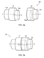
- Figures 3a and 3b show an alternative rotating assembly 10 comprising a first part 11, second part 12 and a third part 13 which are displaced along a geometric axis A.
- Figures 3a and 3b are merely schematic and are intended to illustrate the underlying principal of the invention.
- the precise overall shape of the various parts 11, 12 and 13 may vary in practice and the parts might form part of any number of different possible rotating assemblies such as, for example, a rotor assembly in a gas turbine application.
- the first part 11 might generally be described as an "eccentric cylinder", in the sense that it comprises a first cylindrical section 11a configured to be mounted on an associated bearing (not shown) for rotation, relative to the bearing, about the geometric axis A shown in Figure 3a , and a second cylindrical section 11b fixed to the cylindrical section 11 a and centred on a second (longitudinal) axis B eccentric to the geometric axis A.
- the second part 12 is also generally cylindrical and comprises a cylindrical bore 12a corresponding in dimensions to the second cylindrical section 11b on the first part 11. As best shown in Figure 3b , the cylindrical bore 12a and cylindrical section 11 b can thus be rotatably engaged with one another to rotatably mount the second part 12 on the first part 11, whereby the second part 12 can be rotated, relative to the first part 11, about the second axis B.
- the third part 13 is rotatably supported on the second part 12 for rotation, relative to the second part 12, about a third axis C.
- the third part 13 is shown in Figures 3a and 3b as a simple cylinder, but in practice might be any individual component or form part of a larger sub-assembly.
- the rotating assembly 10 is rotated in its entirety about the geometric axis of rotation A and, again, it is desirable that the centre of mass of the assembly 10 be co-incident with the geometric axis of rotation A.
- Figure 4 illustrates how independent angular adjustment of the first and second parts 11,12 and the third part 13 can be used to adjust the centre-of-mass of the rotating assembly 10 so that it coincides with the geometric axis of rotation A in Figure 3a .
- the distance between the third axis C and the geometric axis A can be varied between zero and an upper limit D, corresponding to the diameter of the circular path 14.
- the radial distance of the centre-of-mass of the assembly 10 from the axis C will remain fixed and therefore, by adjusting the angular position of the first part 11 and second part 12 about the axis B, the geometric axis A can effectively be positioned at the same radial distance from the axis C as the centre-of-mass of the assembly 10.
- the third part 13 can then be independently rotated relative to the combination of the first part 11, second part 12 and associated bearing (not shown) to adjust the angular position of the centre-of-mass of the assembly 10 and the geometric axis A, about the axis C, until the centre-of-mass and geometric axis A are co-incident.
- the lines 14 and 15 in Figure 4 illustrate adjustment of a hypothetical centre-of-mass H at a (fixed) radial distance d from the third axis C so that it is co-incident with the geometric axis A.
- An indication of the initial position of the centre-of-mass of the rotating assembly 3 or 10 can be determined using conventional balancing technology, for example a conventional static balancer or dynamic balancer and, once the centre of mass of the rotating assembly 3, 10 has been adjusted to be co-incident with the geometric axis of rotation A in the manner described above, the first, second and third part of the rotating assembly 3, 10 can then be fixed relative to one another in conventional manner, for subsequent operational rotation of the entire rotating assembly 3, 10 about the geometric axis A as required.
- the fixing means for the first, second and third parts add significant weight to the rotating assembly (ie sufficient weight to alter the position of the centre of mass of the rotating assembly 3) the fixing means should initially be incorporated in the rotating assembly 3, 10 during the balancing operation.
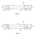
- Figures 5 illustrates a rotating arrangement comprising a rotating assembly 16 similar to the rotating arrangement 10, but which comprises a pair of first parts 17 corresponding to the first part 11, a pair of second parts 18 corresponding to the second part 12, and a third part 19 corresponding to the third part 13.
- the first parts 17 are mounted on a respective pair of bearings 20 (shown only very schematically in Figure 5 ) for rotation about a geometric axis A (corresponding to the axis A in relation to rotating assembly 10).
- the second parts 18 are each mounted on the respective first parts 17 for rotation about an eccentric axis B (corresponding to the axis B in relation to rotating assembly 10), whilst the third part 19 is mounted to each of the second parts 18 for rotation relative to the second parts 18 about a third axis C (corresponding to the axis C in relation to rotating assembly 10).
- the rotating assembly 16 is shown in Figure 5 in a "zero unbalance compensation" configuration, but can be used in essentially the same way as the rotating assembly 10 to adjust the centre of mass of the rotating assembly 16 to be co-incident with the geometric axis of rotation A.
- Figure 6 shows the rotating assembly 16 in a configuration compensating for a static unbalance in the assembly 16, whereby the centre-of-mass of the assembly has been adjusted to be co-incident with the geometric axis A.
- the dynamic unbalance in the rotating assembly 16 only comprises a static component of unbalance
- adjusting the centre-of-mass of the assembly 16 to be co-incident with the geometric axis of rotation A in this manner will also dynamically balance the assembly 16 for rotation about the axis A.
- this component of couple unbalance can additionally be compensated for by opposing angular adjustment of the second parts 18 relative to the respective first parts 17, as shown in Figure 7 , so as to adjust the principal inertia axis of the rotating assembly 16 to be aligned with, or at least parallel to, the geometric axis of rotation A.
Landscapes
- Engineering & Computer Science (AREA)
- General Engineering & Computer Science (AREA)
- Mechanical Engineering (AREA)
- Physics & Mathematics (AREA)
- Acoustics & Sound (AREA)
- Aviation & Aerospace Engineering (AREA)
- Ocean & Marine Engineering (AREA)
- Turbine Rotor Nozzle Sealing (AREA)
- Support Of The Bearing (AREA)
Abstract
i) a first part (4,11,17) mounted on the bearing (2,20) for rotation relative to the bearing (2,20) about the geometric axis (A);
ii) a second part (5,12,18) engaged with the first part (4,11,17) for independent relative angular adjustment about a second axis (B), eccentric to the geometric axis (A), and
iii) a third part (6,13,19) engaged with the second part (5,12,18) for independent relative angular adjustment about a third axis (C), eccentric to the second axis (B);
whereby said relative angular adjustment about one or both of the second (B) and third axes (C) can be used to adjust the position of the centre of mass (F) of the rotating assembly to be substantially co-incident with the geometric axis of rotation (A).
Description
- The present invention relates to a rotating arrangement comprising a rotating assembly mounted on a bearing, for example a rotor assembly in a gas turbine, and more particularly to developments in or relating to the balancing of such a rotating assembly.
- It is known to balance rotating components in various applications, principally in order to reduce unwanted noise, vibration and excessive wear to associated bearings.
- Rotating components can be balanced by re-distributing the mass of the component so that the centre of mass of the component coincides with the geometric axis of rotation of the component.
- A common method of re-distributing the mass of the component, in order to balance the component, is to add material to the component or to remove material from the component. However, each of these methods carries an associated weight penalty, which can be particularly critical in, for example, aerospace applications. In the case of balance methods where material is removed from the component during balancing, this weight penalty arises from the fact that the component must initially be provided with additional, sacrificial material that can be removed for balancing purposes, but which almost inevitably is not entirely removed during the balancing process.
- The weight penalty associated with balancing of rotating components can be reduced to a certain extent using so-called "mass centring" balancing methods, which involve machining the location features of the component according to an offset calculated following an initial balancing operation, such that the position of the geometric axis of rotation (defined by the location features) is made to be coincident with the centre of mass of the component. However, such mass centring balancing methods have the disadvantage that machining of the location features is permanent. This is a particular problem when it is required to balance a rotating assembly rather than a single, individual component because routine strip and rebuild of the rotating assembly can result in a small but significant change in the position of the centre of mass of the assembly relative to the geometric axis of rotation defined by the permanent location features, so that the location features are then effectively in the wrong position for the re-assembled rotating assembly. It may be possible to re-balance the assembly by adding or removing material from the assembly but providing for re-balancing in this manner will again carry an undesirable weight penalty.
- It is an object of this invention to seek to overcome one or more of the above disadvantages associated with existing balancing methods.
- According to the present invention there is provided a rotating arrangement comprising a rotating assembly mounted on an associated bearing defining a geometric axis of rotation for the rotating assembly, the rotating assembly comprising:
- i) a first part mounted on the bearing for rotation relative to the bearing about the geometric axis;
- ii) a second part engaged with the first part for independent relative angular adjustment about a second axis, eccentric to the geometric axis; and
- iii) a third part engaged with the second part for independent relative angular adjustment about a third axis, eccentric to the second axis;
- The bearing may be a circular ring bearing defining the geometric axis and the first part may be an outer eccentric support member rotatably mounted concentrically within the ring bearing, the second part being rotatably supported inside the outer eccentric support member for said angular adjustment relative to the outer eccentric support member, about the second axis.
- Preferably, the second part is an inner eccentric support member nested within the outer eccentric support member, the third part being rotatably supported inside the inner eccentric member for said independent, angular adjustment relative to the inner eccentric support member, about the third axis.
- The first, second and third parts need not be co-planar, and can be displaced along the geometric axis of rotation of the assembly.
- Preferably, the distance between the second axis and the geometric axis is substantially equal to the distance between the third axis and the second axis.
- In one embodiment, the rotatating assembly is mounted on a spaced-apart pair of said bearings and the rotating assembly comprises a corresponding pair of said first parts and corresponding pair of said second parts, the respective axial ends of said third part being engaged with the second parts, whereby opposing angular adjustment of the second parts relative to the respective first parts can be used to adjust the principal inertia axis to be aligned with, or parallel to, the geometric axis of rotation.
- The third part may be a sub-assembly comprising at least two assembled components, for example a rotor assembly.
- According to another aspect of the invention, there is provided a method of balancing the rotating assembly in an arrangement according to any preceding claim, the method comprising the steps of:
- i) determining an unbalance in the rotating assembly; and
- ii) independently adjusting the angular position of each second part relative to one or both of the third part and the corresponding first part to consequently adjust the position of the centre of mass of the rotating assembly to be substantially co-incident with the geometric axis of rotation.
- In order that the invention may more readily be understood, embodiments of the invention will now be described, by way of example, with reference to the accompanying drawings, in which:-
-
Figure 1 is a cross-sectional view of a rotating arrangement comprising a rotatable assembly mounted upon a bearing, looking down the geometric axis of rotation of the rotatable assembly; -
Figure 2 is a schematic diagram illustrating the movement of various parts of the rotatable assembly inFigure 1 relative to the geometric axis of rotation; -
Figure 3a is a partially exploded perspective view showing an alternative rotor arrangement; -
Figure 3b shows the arrangement ofFigure 3a in an assembled state; -
Figure 4 is a schematic view illustrating movement of various parts of the rotatable assembly inFigures 3a and 3b about the geometric axis of rotation; -
Figure 5 is a perspective view of a yet further alternative rotor arrangement shown in a configuration corresponding to zero unbalance compensation; -
Figure 6 is a perspective view of the rotating arrangement shown inFigure 5 , but with the rotating assembly in a configuration for static unbalance compensation; and -
Figure 7 is a perspective view of the rotating arrangement shown inFigure 5 , but with the rotating assembly in a configuration for couple unbalance compensation. -
Figure 1 shows a rotating arrangement 1 comprising a generally planar bearing 2, in this case a circular ball-bearing. For the purposes of clarity, thebearing 2 is shown only diagrammatically and in isolation inFigure 1 , but in practice may form part of a larger assembly such as, for example, a gas turbine or the like. - The first part is an outer eccentric
annular member 4 concentrically mounted on thebearing 2 for rotation about a geometric axis of rotation A at the centre of thecircular bearing 2. Theannular member 4 is generally co-planar with thebearing 2 and is eccentric in the sense that the inner circular periphery of theannular member 4 is centred upon a second axis B that is eccentric to the geometric axis A (ie the second axis B is parallel to, but displaced from, the geometric axis A). - The second part is in the form of an inner eccentric
annular member 5 concentrically supported on the inner circular periphery of theannular member 4 for rotation relative to theannular member 4 about the second axis B. Again, the inner eccentricannular member 5 is generally co-planar with thebearing 2 and is eccentric in the sense that the inner circular periphery of theannular member 5 is centred upon a third axis C, which is eccentric to both the geometric axis A and the second axis B. Thus, if theannular member 5 is rotated around the second axis B, relative to theannular member 4, the third axis C consequently moves around the axis B in a circular orbit. - The
third part 6 is concentrically supported on the inner circular periphery of theannular member 5 for rotation, relative to theannular member 5, about the third axis C. Thethird part 6 may be an individual component such as, for example, a rotatable shaft, or may form part of a larger sub-assembly, for example a rotor assembly in a gas turbine application or the like. - In use, the
rotating assembly 3 is rotated about a geometric axis of rotation A, at the centre of thebearing 2, by rotating the outer eccentricannular member 4 relative to thebearing 2. In order to reduce unwanted vibration, noise and excessive bearing wear on thebearing 2, it is preferable that the centre-of-mass of the rotatingassembly 3 is co-incident with the geometric axis of rotation A and therefore, where the initial mass distribution of therotating assembly 3 is such that the centre-of-mass is offset from the geometric axis of rotation A, the centre-of-mass needs to be adjusted so that as far as possible it is co-incident with the geometric axis of rotation A. -
Figure 2 illustrates how independent angular adjustment of theannular members third part 6 can be used to adjust the centre-of-mass of therotating assembly 3, relative to the geometric axis of rotation A, with the aim of positioning the centre-of-mass of the rotatingassembly 3 on the geometric axis of rotation A. - Thus, referring to
Figure 1 , when the relative angular position of the inner and outerannular members angular member 5 will rotate around the second axis B and thethird part 6 will likewise rotate with theannular member 5 about the second axis B, with the result that the third axis C will effectively trace the circular path 7 shown inFigure 2 , relative to the geometric axis A. (For the purposes of clarity, it is assumed inFigure 2 that the outerannular member 4 remains fixed relative to thebearing 2 during relative angular adjustment of theannular members annular member 4 andbearing 2 will only result in symmetric rotation of the entirerotating assembly 3 about the geometric axis A). - In this manner, the distance between the third axis C and the geometric axis A can be adjusted between a lower limit r (see the position C" for the axis C in
Figure 2 ) and an upper limit R (see the position C' for the axis C inFigure 2 ). At the same time, such adjustment will not substantially affect the radial distance of the centre of mass of the rotatingassembly 3 from the axis C, which will remain effectively fixed. - Thus, by adjusting the relative angular position of the
annular members - Once the centre-of-mass and geometric axis A have been positioned at the same radial distance from the axis C, the
third part 6 can then be independently rotated relative to the combination of thebearing 2 andannular members 4,5 (ie whilst maintaining thebearing 2 andannular members - For example, referring to
Figure 2 , for a hypothetical centre-of-mass F at a radial distance R from the third axis C, the third axis C can be adjusted to the position C' at a distance R from the geometric axis A (by relatively adjusting theannular members third part 6 about the axis C) to bring the centre-of-mass into coincidence with the geometric axis A. Similarly, for a hypothetical centre-of-mass G at a radial distance r from the third axis C, the third axis C can be adjusted to the position C", at a distance r from the geometric axis A, and then the centre-of-mass G and geometric axis A can be angularly adjusted along the dotted path 9, about the axis C, to bring the centre-of-mass G into co-incidence with the geometric axis A. - It will be appreciated that the parameter r is a function of the relative positions of the axes A, B and C, and therefore its value can be minimised as far as possible within specified tolerances. Indeed, it is envisaged that, by equating the (fixed) radial distance of each of the axes A, C relative to the axis B, r can be made to be zero.
-
Figures 3a and 3b show analternative rotating assembly 10 comprising afirst part 11,second part 12 and athird part 13 which are displaced along a geometric axis A. - It should be emphasised here that
Figures 3a and 3b are merely schematic and are intended to illustrate the underlying principal of the invention. In particular, the precise overall shape of thevarious parts - Referring then to
Figure 3a , which shows a partially exploded view of thearrangement 10, thefirst part 11 might generally be described as an "eccentric cylinder", in the sense that it comprises a firstcylindrical section 11a configured to be mounted on an associated bearing (not shown) for rotation, relative to the bearing, about the geometric axis A shown inFigure 3a , and a secondcylindrical section 11b fixed to thecylindrical section 11 a and centred on a second (longitudinal) axis B eccentric to the geometric axis A. - The
second part 12 is also generally cylindrical and comprises acylindrical bore 12a corresponding in dimensions to the secondcylindrical section 11b on thefirst part 11. As best shown inFigure 3b , thecylindrical bore 12a andcylindrical section 11 b can thus be rotatably engaged with one another to rotatably mount thesecond part 12 on thefirst part 11, whereby thesecond part 12 can be rotated, relative to thefirst part 11, about the second axis B. - The
third part 13 is rotatably supported on thesecond part 12 for rotation, relative to thesecond part 12, about a third axis C. Thethird part 13 is shown inFigures 3a and 3b as a simple cylinder, but in practice might be any individual component or form part of a larger sub-assembly. - It should be noted that the radial distance from the axis B to each of the axes A and C is the same.
- In use, the
rotating assembly 10 is rotated in its entirety about the geometric axis of rotation A and, again, it is desirable that the centre of mass of theassembly 10 be co-incident with the geometric axis of rotation A. -
Figure 4 illustrates how independent angular adjustment of the first andsecond parts third part 13 can be used to adjust the centre-of-mass of therotating assembly 10 so that it coincides with the geometric axis of rotation A inFigure 3a . - When the
second part 12 is rotated, relative to thefirst part 11, about the axis B, the third axis C will trace thecircular path 14 shown inFigure 4 . - In this manner, the distance between the third axis C and the geometric axis A can be varied between zero and an upper limit D, corresponding to the diameter of the
circular path 14. At the same time, the radial distance of the centre-of-mass of theassembly 10 from the axis C will remain fixed and therefore, by adjusting the angular position of thefirst part 11 andsecond part 12 about the axis B, the geometric axis A can effectively be positioned at the same radial distance from the axis C as the centre-of-mass of theassembly 10. - Once the centre-of-mass and geometric axis A have been positioned at the same radial distance from the axis C, the
third part 13 can then be independently rotated relative to the combination of thefirst part 11,second part 12 and associated bearing (not shown) to adjust the angular position of the centre-of-mass of theassembly 10 and the geometric axis A, about the axis C, until the centre-of-mass and geometric axis A are co-incident. Thelines Figure 4 illustrate adjustment of a hypothetical centre-of-mass H at a (fixed) radial distance d from the third axis C so that it is co-incident with the geometric axis A. - An indication of the initial position of the centre-of-mass of the
rotating assembly rotating assembly rotating assembly rotating assembly rotating assembly -
Figures 5 illustrates a rotating arrangement comprising a rotatingassembly 16 similar to therotating arrangement 10, but which comprises a pair offirst parts 17 corresponding to thefirst part 11, a pair ofsecond parts 18 corresponding to thesecond part 12, and athird part 19 corresponding to thethird part 13. - The
first parts 17 are mounted on a respective pair of bearings 20 (shown only very schematically inFigure 5 ) for rotation about a geometric axis A (corresponding to the axis A in relation to rotating assembly 10). Similarly, thesecond parts 18 are each mounted on the respectivefirst parts 17 for rotation about an eccentric axis B (corresponding to the axis B in relation to rotating assembly 10), whilst thethird part 19 is mounted to each of thesecond parts 18 for rotation relative to thesecond parts 18 about a third axis C (corresponding to the axis C in relation to rotating assembly 10). - The rotating
assembly 16 is shown inFigure 5 in a "zero unbalance compensation" configuration, but can be used in essentially the same way as the rotatingassembly 10 to adjust the centre of mass of the rotatingassembly 16 to be co-incident with the geometric axis of rotation A. - Thus, by way of example,
Figure 6 shows the rotatingassembly 16 in a configuration compensating for a static unbalance in theassembly 16, whereby the centre-of-mass of the assembly has been adjusted to be co-incident with the geometric axis A. - Where the dynamic unbalance in the rotating
assembly 16 only comprises a static component of unbalance, adjusting the centre-of-mass of theassembly 16 to be co-incident with the geometric axis of rotation A in this manner will also dynamically balance theassembly 16 for rotation about the axis A. However, where the dynamic unbalance incorporates a significant component of couple unbalance, it is envisaged that this component of couple unbalance can additionally be compensated for by opposing angular adjustment of thesecond parts 18 relative to the respectivefirst parts 17, as shown inFigure 7 , so as to adjust the principal inertia axis of the rotatingassembly 16 to be aligned with, or at least parallel to, the geometric axis of rotation A.
Claims (8)
- A rotating arrangement comprising a rotating assembly (3,10,16) mounted on an associated bearing (2) defining a geometric axis of rotation for the rotating assembly, the rotating assembly comprising:i) a first part (4,11,17) mounted on the bearing (2,20) for rotation relative to the bearing (2,20) about the geometric axis (A);ii) a second part (5,12,18) engaged with the first part (4,11,17) for independent relative angular adjustment about a second axis (B), eccentric to the geometric axis (A), andiii) a third part (6,13,19) engaged with the second part (5,12,18) for independent relative angular adjustment about a third axis (C), eccentric to the second axis (B);whereby said relative angular adjustment about one or both of the second (B) and third axes (C) can be used to adjust the position of the centre of mass (F) of the rotating assembly to be substantially co-incident with the geometric axis of rotation (A).
- A rotating arrangement according to claim 1, wherein the bearing is a circular ring bearing (2) defining the geometric axis (A) and the first part is an outer eccentric support member (4) rotatably mounted concentrically within the ring bearing (2), the second part (5) being rotatably supported inside the outer eccentric support member (4) for said angular adjustment relative to the outer eccentric support member (4), about the second axis (B).
- A rotating arrangement according to claim 2, wherein the second part (5) is an inner eccentric support member (5) nested within the outer eccentric support member (4), the third part (6) being rotatably supported inside the inner eccentric member (5) for said independent, angular adjustment relative to the inner eccentric support member (5), about the third axis (C).
- A rotating arrangement according to claim 1, wherein the first (11,17), second (12,18) and third (13,19) parts are displaced along the geometric axis (A).
- A rotating arrangement according to claim 4, wherein the distance between the second axis (B) and the geometric axis (A) is substantially equal to the distance between the third axis (C) and the second axis (B).
- A rotating arrangement according to any preceding claim, wherein the rotatating assembly (16) is mounted on a spaced-apart pair of said bearings (20) and the rotating assembly (16) comprises a corresponding pair of said first parts (17) and corresponding pair of said second parts (18), the respective axial ends of said third part (19) being engaged with the second parts (18), whereby opposing angular adjustment of the second parts (18) relative to the first parts (17) can be used to adjust the principal inertia axis to be aligned with, or parallel to, the geometric axis of rotation (A).
- A rotating arrangement according to any preceding claim, wherein the third part (6,13,19) is a sub-assembly comprising at least two assembled components.
- A method of balancing the rotating assembly (3,10,16) in an arrangement according to any preceding claim, the method comprising the steps of:i) determining an unbalance in the rotating assembly (3,10,16); andii) independently adjusting the angular position of each second part (5,12,18) relative to one or both of the third part (6,13,19) and the corresponding first part (4,11,17) to consequently adjust the position of the centre of mass (F) of the rotating assembly (3,10,16) to be substantially co-incident with the geometric axis of rotation (A).
Applications Claiming Priority (1)
| Application Number | Priority Date | Filing Date | Title |
|---|---|---|---|
| GB0724818A GB2455752B (en) | 2007-12-20 | 2007-12-20 | Developments in or relating to the balancing of a rotating assembly |
Publications (2)
| Publication Number | Publication Date |
|---|---|
| EP2083181A1 true EP2083181A1 (en) | 2009-07-29 |
| EP2083181B1 EP2083181B1 (en) | 2010-07-21 |
Family
ID=39048410
Family Applications (1)
| Application Number | Title | Priority Date | Filing Date |
|---|---|---|---|
| EP08019252A Not-in-force EP2083181B1 (en) | 2007-12-20 | 2008-11-04 | Developments in or relating to the balancing of a rotating assembly |
Country Status (4)
| Country | Link |
|---|---|
| US (1) | US20090163284A1 (en) |
| EP (1) | EP2083181B1 (en) |
| DE (1) | DE602008001869D1 (en) |
| GB (1) | GB2455752B (en) |
Families Citing this family (2)
| Publication number | Priority date | Publication date | Assignee | Title |
|---|---|---|---|---|
| CN108240393A (en) * | 2017-12-04 | 2018-07-03 | 安徽未来机电科技有限公司 | The capacity eccentric bearing bar and its adjusting method of a kind of variable axial center type |
| DE202024105874U1 (en) | 2024-10-11 | 2026-02-19 | Novopress Gmbh Pressen Und Presswerkzeuge & Co. Kommanditgesellschaft | Drive unit for a pressing device |
Citations (7)
| Publication number | Priority date | Publication date | Assignee | Title |
|---|---|---|---|---|
| DE941880C (en) * | 1951-06-09 | 1956-04-19 | Kloeckner Humboldt Deutz Ag | Device for automatic adjustment of the injection time of the injection pump of an internal combustion engine |
| US5237892A (en) * | 1992-07-28 | 1993-08-24 | Tecumseh Products Company | Reduced material crankshaft fabrication |
| US5259677A (en) | 1992-10-26 | 1993-11-09 | The Torrington Company | Axially restrained and balanced eccentric bearing |
| DE19830930A1 (en) * | 1998-07-10 | 2000-01-13 | Bauss Hans Werner | Angular adjustment for shaft and drive wheel |
| DE102004007052A1 (en) * | 2004-02-13 | 2005-09-08 | Daimlerchrysler Ag | Phase angle adjustment system for camshaft in internal combustion engine has eccentric drive with external toothed pinion engaging gear ring driven by timing chain |
| DE102004007050A1 (en) * | 2004-02-13 | 2005-09-08 | Daimlerchrysler Ag | Phase adjustment system for shaft concentric with chain drive wheel has hydraulic motor with vanes and eccentric rotor with drive pinion inside housing with sprocket teeth |
| DE102005013141A1 (en) * | 2005-03-22 | 2006-09-28 | Schaeffler Kg | Device for camshaft adjustment in internal combustion (IC) engine, has labyrinth seals for suppressing oil leakage between device components, including inner and outer rotors, side panels, and extension elements |
Family Cites Families (6)
| Publication number | Priority date | Publication date | Assignee | Title |
|---|---|---|---|---|
| US2285404A (en) * | 1940-09-25 | 1942-06-09 | Best Frank Ellison | Means for and method of dynamically balancing rotary machine parts |
| US3099349A (en) * | 1960-12-06 | 1963-07-30 | Adamson Stephens Mfg Co | Eccentric drive for vibrating conveyor |
| US4035044A (en) * | 1976-06-17 | 1977-07-12 | Sadao Miyazaki | Bearing assembly |
| US4440123A (en) * | 1982-01-28 | 1984-04-03 | General Motors Corporation | Half speed balancer |
| US4909641A (en) * | 1988-08-25 | 1990-03-20 | The Torrington Company | Bearing with expanded load zone |
| JP2003120711A (en) * | 2001-10-10 | 2003-04-23 | Tomoe Engineering Co Ltd | Joint mechanism with automatic aligning function and rotor assembly having this mechanism |
-
2007
- 2007-12-20 GB GB0724818A patent/GB2455752B/en not_active Expired - Fee Related
-
2008
- 2008-11-04 EP EP08019252A patent/EP2083181B1/en not_active Not-in-force
- 2008-11-04 DE DE602008001869T patent/DE602008001869D1/en active Active
- 2008-11-07 US US12/289,960 patent/US20090163284A1/en not_active Abandoned
Patent Citations (7)
| Publication number | Priority date | Publication date | Assignee | Title |
|---|---|---|---|---|
| DE941880C (en) * | 1951-06-09 | 1956-04-19 | Kloeckner Humboldt Deutz Ag | Device for automatic adjustment of the injection time of the injection pump of an internal combustion engine |
| US5237892A (en) * | 1992-07-28 | 1993-08-24 | Tecumseh Products Company | Reduced material crankshaft fabrication |
| US5259677A (en) | 1992-10-26 | 1993-11-09 | The Torrington Company | Axially restrained and balanced eccentric bearing |
| DE19830930A1 (en) * | 1998-07-10 | 2000-01-13 | Bauss Hans Werner | Angular adjustment for shaft and drive wheel |
| DE102004007052A1 (en) * | 2004-02-13 | 2005-09-08 | Daimlerchrysler Ag | Phase angle adjustment system for camshaft in internal combustion engine has eccentric drive with external toothed pinion engaging gear ring driven by timing chain |
| DE102004007050A1 (en) * | 2004-02-13 | 2005-09-08 | Daimlerchrysler Ag | Phase adjustment system for shaft concentric with chain drive wheel has hydraulic motor with vanes and eccentric rotor with drive pinion inside housing with sprocket teeth |
| DE102005013141A1 (en) * | 2005-03-22 | 2006-09-28 | Schaeffler Kg | Device for camshaft adjustment in internal combustion (IC) engine, has labyrinth seals for suppressing oil leakage between device components, including inner and outer rotors, side panels, and extension elements |
Also Published As
| Publication number | Publication date |
|---|---|
| GB0724818D0 (en) | 2008-01-30 |
| GB2455752B (en) | 2009-11-04 |
| GB2455752A (en) | 2009-06-24 |
| US20090163284A1 (en) | 2009-06-25 |
| EP2083181B1 (en) | 2010-07-21 |
| DE602008001869D1 (en) | 2010-09-02 |
Similar Documents
| Publication | Publication Date | Title |
|---|---|---|
| US8051710B2 (en) | Method and apparatus for balancing a rotor | |
| US7793540B2 (en) | Rotor unbalance correction | |
| KR101584159B1 (en) | Passive dynamic inertial rotor balance system for turbomachinery | |
| US5201585A (en) | Fluid film journal bearing with squeeze film damper for turbomachinery | |
| US9388848B2 (en) | Radial gas foil bearing | |
| JP5585082B2 (en) | Vacuum pump | |
| JP7078755B2 (en) | Flywheel with tuned mass damper | |
| US10436224B2 (en) | Method and apparatus for balancing a rotor | |
| EP3470810B1 (en) | Vibration isolation member and imbalance detector equipped with vibration isolation member | |
| JPS6346289B2 (en) | ||
| KR20150032338A (en) | Rotor assembly | |
| US9932832B2 (en) | Method of balancing a spool of a gas turbine engine | |
| JP7573552B2 (en) | ROTOR SUPPORT AND VACUUM PUMP EQUIPPED WITH SUCH A ROTOR SUPPORT - Patent application | |
| US6626574B2 (en) | Squeeze film damping type bearing | |
| EP2083181B1 (en) | Developments in or relating to the balancing of a rotating assembly | |
| EP2795166A1 (en) | Coning resistant rotor for a seal assembly | |
| KR0147691B1 (en) | Shaft mount with tilt correction | |
| JP3773709B2 (en) | High-speed rotating body balance correction method | |
| JP2002221003A (en) | Rotor balancing method, apparatus therefor, and rotor | |
| CN109505863B (en) | Bearing and eccentricity correction method | |
| US9624775B2 (en) | Developments in or relating to rotor balancing | |
| CA3151896A1 (en) | Compressor device and device equipped with a bearing damper | |
| US10408229B2 (en) | Balancing device | |
| EP2792849B1 (en) | Developments in or relating to rotor balancing | |
| JPH0314944A (en) | Resilient rotary shaft of long cyrindrical shape |
Legal Events
| Date | Code | Title | Description |
|---|---|---|---|
| PUAI | Public reference made under article 153(3) epc to a published international application that has entered the european phase |
Free format text: ORIGINAL CODE: 0009012 |
|
| AK | Designated contracting states |
Kind code of ref document: A1 Designated state(s): AT BE BG CH CY CZ DE DK EE ES FI FR GB GR HR HU IE IS IT LI LT LU LV MC MT NL NO PL PT RO SE SI SK TR |
|
| AX | Request for extension of the european patent |
Extension state: AL BA MK RS |
|
| 17P | Request for examination filed |
Effective date: 20090814 |
|
| 17Q | First examination report despatched |
Effective date: 20090917 |
|
| GRAP | Despatch of communication of intention to grant a patent |
Free format text: ORIGINAL CODE: EPIDOSNIGR1 |
|
| GRAS | Grant fee paid |
Free format text: ORIGINAL CODE: EPIDOSNIGR3 |
|
| AKX | Designation fees paid |
Designated state(s): DE FR GB |
|
| RBV | Designated contracting states (corrected) |
Designated state(s): DE FR |
|
| GRAA | (expected) grant |
Free format text: ORIGINAL CODE: 0009210 |
|
| AK | Designated contracting states |
Kind code of ref document: B1 Designated state(s): DE FR |
|
| REF | Corresponds to: |
Ref document number: 602008001869 Country of ref document: DE Date of ref document: 20100902 Kind code of ref document: P |
|
| PLBE | No opposition filed within time limit |
Free format text: ORIGINAL CODE: 0009261 |
|
| STAA | Information on the status of an ep patent application or granted ep patent |
Free format text: STATUS: NO OPPOSITION FILED WITHIN TIME LIMIT |
|
| 26N | No opposition filed |
Effective date: 20110426 |
|
| REG | Reference to a national code |
Ref country code: DE Ref legal event code: R097 Ref document number: 602008001869 Country of ref document: DE Effective date: 20110426 |
|
| REG | Reference to a national code |
Ref country code: FR Ref legal event code: PLFP Year of fee payment: 8 |
|
| REG | Reference to a national code |
Ref country code: FR Ref legal event code: PLFP Year of fee payment: 9 |
|
| REG | Reference to a national code |
Ref country code: FR Ref legal event code: CA Effective date: 20170517 |
|
| REG | Reference to a national code |
Ref country code: FR Ref legal event code: PLFP Year of fee payment: 10 |
|
| PGFP | Annual fee paid to national office [announced via postgrant information from national office to epo] |
Ref country code: DE Payment date: 20191127 Year of fee payment: 12 |
|
| PGFP | Annual fee paid to national office [announced via postgrant information from national office to epo] |
Ref country code: FR Payment date: 20191125 Year of fee payment: 12 |
|
| REG | Reference to a national code |
Ref country code: DE Ref legal event code: R119 Ref document number: 602008001869 Country of ref document: DE |
|
| PG25 | Lapsed in a contracting state [announced via postgrant information from national office to epo] |
Ref country code: FR Free format text: LAPSE BECAUSE OF NON-PAYMENT OF DUE FEES Effective date: 20201130 |
|
| PG25 | Lapsed in a contracting state [announced via postgrant information from national office to epo] |
Ref country code: DE Free format text: LAPSE BECAUSE OF NON-PAYMENT OF DUE FEES Effective date: 20210601 |