EP2082926A1 - Pretensioner and seat belt apparatus - Google Patents
Pretensioner and seat belt apparatus Download PDFInfo
- Publication number
- EP2082926A1 EP2082926A1 EP08021236A EP08021236A EP2082926A1 EP 2082926 A1 EP2082926 A1 EP 2082926A1 EP 08021236 A EP08021236 A EP 08021236A EP 08021236 A EP08021236 A EP 08021236A EP 2082926 A1 EP2082926 A1 EP 2082926A1
- Authority
- EP
- European Patent Office
- Prior art keywords
- housing
- seal
- wire
- seat belt
- pretensioner
- Prior art date
- Legal status (The legal status is an assumption and is not a legal conclusion. Google has not performed a legal analysis and makes no representation as to the accuracy of the status listed.)
- Granted
Links
- 230000001681 protective effect Effects 0.000 claims abstract description 90
- 238000004512 die casting Methods 0.000 claims abstract description 11
- 230000000452 restraining effect Effects 0.000 claims description 8
- 229910000838 Al alloy Inorganic materials 0.000 claims description 3
- 239000000463 material Substances 0.000 abstract description 11
- 210000000078 claw Anatomy 0.000 abstract description 10
- 229910045601 alloy Inorganic materials 0.000 abstract description 8
- 239000000956 alloy Substances 0.000 abstract description 8
- 229910052782 aluminium Inorganic materials 0.000 abstract description 8
- XAGFODPZIPBFFR-UHFFFAOYSA-N aluminium Chemical compound [Al] XAGFODPZIPBFFR-UHFFFAOYSA-N 0.000 abstract description 8
- 238000002788 crimping Methods 0.000 abstract description 7
- 238000004804 winding Methods 0.000 description 8
- 238000000034 method Methods 0.000 description 4
- 229910052751 metal Inorganic materials 0.000 description 3
- 239000002184 metal Substances 0.000 description 3
- 230000005489 elastic deformation Effects 0.000 description 2
- 238000000465 moulding Methods 0.000 description 2
- 239000000654 additive Substances 0.000 description 1
- 230000007423 decrease Effects 0.000 description 1
- 230000003247 decreasing effect Effects 0.000 description 1
- 230000001419 dependent effect Effects 0.000 description 1
- 238000001514 detection method Methods 0.000 description 1
- 230000000694 effects Effects 0.000 description 1
- 229920001971 elastomer Polymers 0.000 description 1
- 239000011796 hollow space material Substances 0.000 description 1
- 239000003562 lightweight material Substances 0.000 description 1
- 239000005060 rubber Substances 0.000 description 1
- 238000007789 sealing Methods 0.000 description 1
- 229920003051 synthetic elastomer Polymers 0.000 description 1
- 239000005061 synthetic rubber Substances 0.000 description 1
Images



Classifications
-
- B—PERFORMING OPERATIONS; TRANSPORTING
- B60—VEHICLES IN GENERAL
- B60R—VEHICLES, VEHICLE FITTINGS, OR VEHICLE PARTS, NOT OTHERWISE PROVIDED FOR
- B60R22/00—Safety belts or body harnesses in vehicles
- B60R22/18—Anchoring devices
- B60R22/195—Anchoring devices with means to tension the belt in an emergency, e.g. means of the through-anchor or splitted reel type
- B60R22/1952—Transmission of tensioning power by cable; Return motion locking means therefor
-
- B—PERFORMING OPERATIONS; TRANSPORTING
- B60—VEHICLES IN GENERAL
- B60R—VEHICLES, VEHICLE FITTINGS, OR VEHICLE PARTS, NOT OTHERWISE PROVIDED FOR
- B60R22/00—Safety belts or body harnesses in vehicles
- B60R22/18—Anchoring devices
- B60R22/195—Anchoring devices with means to tension the belt in an emergency, e.g. means of the through-anchor or splitted reel type
- B60R22/1954—Anchoring devices with means to tension the belt in an emergency, e.g. means of the through-anchor or splitted reel type characterised by fluid actuators, e.g. pyrotechnic gas generators
- B60R22/1955—Linear actuators
Definitions
- the present invention relates to a pretensioner which pulls a seat belt at the time of a rapid deceleration of a vehicle and relates to a seat belt apparatus.
- vehicle seats are equipped with seat belt apparatuses for restraining occupants each of which prevents the occupant from being moved forward due to an inertial force when an impact is generated, for example, at the time of a rapid deceleration or a collision of the vehicle.
- a seat belt apparatus is generally provided with an Emergency Locking Retractor (hereinafter, referred to as an ELR) which does not restrain motion of the occupant in normal driving but locks a winding shaft for the seat belt to prevent the seat belt from being further withdrawn only when an impact is generated to the vehicle.
- the ELR locks the winding shaft within a very short time after detecting a deceleration of a predetermined value or more, thereby preventing the seat belt from being further withdrawn.
- the pretensioner as disclosed in JP-A-2003-146184 comprises a wire of which one end is connected to a seat belt buckle and the other end is fixed to a piston in a cylinder and a housing through which the wire is passed and which supports the cylinder.
- high-pressure gas is spouted into a gas chamber formed in the housing so as to move the piston, thereby pulling the wire.
- a holder Mounted on the other side of the housing from the cylinder is a holder having a guide hole for guiding the wire toward the cylinder.
- a protection member (guard pipe) for protecting the wire is disposed inside the gas chamber to cover the outer periphery of the wire and a seal member is disposed on the other side of the housing from the cylinder to seal between the gas chamber and the guide hole of the holder.
- the seal member is fixed inside the housing to prevent the seal member from being pulled according to the pulling of the wire during the actuation of the pretensioner.
- a plurality of engaging claws are formed by metallic molding at a plurality of locations in the circumferential direction of the inner wall of the housing and these claws are crimped to hold the seal member.
- the housing is a die-casting product made of aluminum alloy
- reduction in weight of the housing is achieved.
- the elongation of the material is small, it is impossible to efficiently crimp the engaging claws to hold the seal member. That is, it is difficult to fix the seal member inside the housing by crimping the claws.
- a pretensioner for restraining an occupant with a seat belt by pulling the seat belt when an impact on a vehicle is generated comprises: a wire of which one end is connected to the seat belt; a piston which is connected to the other end of said wire to pull said wire; a cylinder which accommodates said piston slidably; a housing through which said wire is inserted and which holds said cylinder at one end thereof; a holder which is located at the other end of said housing and has a guide hole for guiding said wire toward said cylinder; a gas generator which supplies gas for moving said piston into said cylinder through a gas chamber formed in said housing; a protective member for protecting said wire which is disposed in said gas chamber within said housing to cover at least an outer periphery of said wire facing said gas generator; and a seal member which is located within said housing at a side of said protective member opposite to said cylinder side to seal between said gas chamber and said guide hole of said holder and through which said wire is inserted, and is characterized by further comprising
- the pretensioner is actuated to improve the restraint force for an occupant by the seat belt so that high-pressure gas from the gas generator is supplied into the cylinder through the gas chamber in the housing and the piston within the cylinder is moved, thereby pulling the wire. According to the pulling of the wire, the seat belt is pulled.
- the seal member is fixed inside the housing.
- the housing is made of a material having small elongation such as aluminum die-casting alloy in a case of fixing the seal member inside the housing by crimping engaging claws which are formed on the housing by molding, it is difficult to fix the seal member.
- the retaining ring is a fixing member of a simple structure which is made of an elastic metal and comprises a thin ring and a plurality of projections which project radially outwardly from the periphery of the thin ring, a simple structure of the fixing member for the seal member is achieved.
- the ring of the retaining ring is brought in contact with the end of the seal member facing the protecting member and the retaining ring is press fitted into the gas chamber so that the projections are elastically deformed by press contact with the inner wall of the housing defining the gas chamber. Because of the elastic force, the retaining ring is engaged with the inner wall of the housing. The seal member is easily fixed in this manner.
- said protective member and said seal member are formed as an integral protective seal, that said retaining ring is fitted onto the outer periphery of the protective member to hold the protective seal, and that said protective seal is fixed to the inner wall of said housing by said retaining ring.
- the seal member may be formed integrally with the protective member to compose an integral protective seal, not a member separate from the protective member.
- the seal member is continued to the protective member at an end having a larger diameter.
- the protective seal is held by the retaining ring.
- the projections are elastically deformed by press contact with the inner wall of the housing defining the gas chamber. Because of the elastic force, the retaining ring is engaged with the inner wall of the housing, whereby the seal member together with the protective member is fixed to the inner wall of the housing.
- the seal member and the protective member are integrally formed, thereby reducing the number of parts as compared to the case that the seal member and the protective member are separately formed and thus reducing the material cost and the assembling cost.
- the outer periphery of said protective member is provided with a plurality of through holes capable of diffusing said gas.
- high temperature gas from the gas generator is sent into the protective member through the through holes so as to flow the high temperature gas along grooves formed in the outer periphery of twist of the wire within the protective member. Therefore, the contact area of the high temperature gas relative to the wire is increased so that local elevation of temperature of the wire is prevented and the wire is thus protected. In addition, the temperature of the high temperature gas can be greatly cooled, thereby securely preventing the high temperature gas (e.g. flame) from spurting out of the housing.
- the high temperature gas e.g. flame
- said housing is a die-casting product made of aluminum alloy.
- a seat belt apparatus includes a seat belt; a retractor which wind up said seat belt; a tongue supported by said seat belt; a pretensioner for restraining an occupant with the seat belt by pulling said seat belt when an impact on a vehicle is generated, wherein said pretensioner comprises: a wire of which one end is connected to the seat belt; a piston which is connected to the other end of said wire to pull said wire; a cylinder which accommodates said piston slidably; a housing through which said wire is inserted and which holds said cylinder at one end thereof; a holder which is located at the other end of said housing and has a guide hole for guiding said wire toward said cylinder; a gas generator which supplies gas for moving said piston into said cylinder through a gas chamber formed in said housing; a protective member for protecting said wire which is disposed in said gas chamber within said housing to cover at least an outer periphery of said wire facing said gas generator; and a seal member which is located within said housing at a side of said protective member opposite
- the seat belt apparatus employs the aforementioned pretensioner, the reduction in weight of the pretensioner is achieved.
- a retaining ring having a plurality of projections radially outwardly projecting form the periphery of an annular ring is used to fix a seal member inside a housing of a pretensioner, simple structure of the fixing member is achieved and the seal member can be easily fixed to the inside of the housing.
- the fixing of the seal member is achieved without crimping engaging claws, a material of which elongation is small but weight is light such as aluminum die-casting alloy can be used to make the housing, thereby enabling reduction in weight of the housing.
- Fig. 1 is a perspective view showing a seat belt apparatus with a pretensioner of the embodiment of the present invention.
- the seat belt apparatus 1 comprises a seat belt 3 for restraining an occupant which can be withdrawn from a retractor 2.
- the retractor 2 is a device for winding up the seat belt 3 and is fixed to a lower portion of a center pillar 4 in a cabin of a vehicle.
- the seat belt 3 withdrawn from the retractor 2 to extend toward an upper portion of the vehicle passes through a through ring 5 attached to an upper portion of the center pillar 4 and is bent at the through ring 5 to extend toward a lower portion of the vehicle.
- the distal end of the seat belt 3 is fixed to an anchor plate 7 which is disposed between the center pillar 4 and a seat 6.
- a tongue 8 is attached to the seat belt 3 such that the seat belt 3 passes through the tongue 8.
- the tongue 8 can be detachably latched with a seat belt buckle 9 which is disposed on a side opposite to the anchor plate 7 relative to the seat 6.
- the pretensioner 10 of this embodiment is attached to the seat belt buckle 9.
- the pretensioner 10 is a device for pulling the seat belt 3 via the seat belt buckle 9 when an impact is generated, for example, at the time of a sudden stop or a collision of the vehicle, thereby restraining the occupant with the seat belt 3.
- the pretensioner 10 comprises a wire 11 connected to the seat belt buckle 9, a housing 12 through which the wire 11 is inserted, a cylinder 14 which is supported by one end of the housing 12, a holder 13 which is attached to the other end of the housing 12 and has a guide portion 13a and a guide hole 13b (see Fig. 2 ) for guiding the wire 11 toward the cylinder 14 such that a portion of the wire 11 is bent.
- the pretensioner 10 is mounted by fixing the housing 12 to, for example, a vehicle body (seat) directly or via a bracket (not shown).
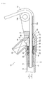
- Fig. 2 is a vertical sectional view of the pretensioner 10.
- one end of the wire 11 is connected to the seat belt buckle 9 (see Fig. 1 ) and the other end of the wire 11 is connected to a piston 15.
- the piston 15 is slidably accommodated in the cylinder 14.
- the piston 15 comprises a piston main body 16 through which the wire 11 is inserted, and a wire holding portion 17 which is connected to an end of the piston main body 16 and fixes the other end of the wire 11.
- a wire holding portion 17 which is connected to an end of the piston main body 16 and fixes the other end of the wire 11.
- the piston main body 16 has a tapered portion 20 which is formed on the distal end side (on the side of the wire holding portion 17) relative to the annular groove 18 and gradually increases in diameter toward the distal end side. Between the tapered portion 20 and the inner wall of the cylinder 14, a ball ring 21 and a plurality of balls 22 are arranged. This arrangement allows the piston 15 to move in a direction toward the distal end (direction A) and prevents the piston 15 from moving in a direction toward the proximal end (direction B).
- the housing 12 for supporting the cylinder 14 is provided with a gas generator 23 which generates high-pressure gas for moving the piston 15 in the direction A.
- the gas generator 23 has a gas generating section and an ignition section which are not shown. As a rapid deceleration of the vehicle is detected by, for example, a sensor (not shown), an ignition signal is transmitted to the ignition section so that the ignition section is activated and the gas generating section spouts out high-temperature high-pressure gas into a gas chamber 24 in the housing 12.
- the gas chamber (gas passage) 24 for supplying the high-pressure gas spouted from the gas generator 23 to the cylinder 14 and a seal receiving portion 25 which communicates with a gas chamber 24 located on a side opposite to the cylinder 14 with regard to the gas chamber 24 are formed.
- the seal receiving portion 25 is a tapered hollow space gradually decreasing in diameter toward the holder 13.
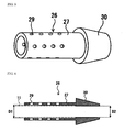
- a protective seal 26, comprising a protective member 27 and a seal member 30 which are integrated, is arranged in the housing 12 and is fixed in the housing 12 by a retaining ring 40 as will be described later.
- the protective member 27 is a member for protecting at least an outer surface of the wire 11 exposed to the gas generator 23 from high temperature gas from the gas generator 23.
- the protective member 27 is formed in a cylindrical shape extending to a position spaced a little from the proximal end 16a of the piston main body 16 in the gas chamber 24 so as to cover substantially the entire of the wire 11 positioned within the gas chamber 24 to protect the outer periphery thereof. It should be noted that the protective member 27 may extend to a position being in contact with the proximal end 16a of the piston body 16 in the gas chamber 24.
- the seal member 30 of the protective seal 26 is formed integrally with an end of the protective member 27 opposite to the cylinder 17.
- the seal member 30 is arranged in the seal receiving portion 25 to seal between the gas chamber 24 and the guide hole 13b of the holder 13.
- the seal member 30 is a circular truncated cone-shaped annular body through which the wire 11 is inserted, and is continued to the protective member 27 at an end having a larger diameter.
- the seal member 30 gradually decreases in diameter toward the holder 13 corresponding to the inner diameter of the seal receiving portion 25 and has such a length that the end of the seal member 30 on the side of the protective member 27 slightly projects from the seal receiving portion 25.
- the protective seal 26 composed of the protective member 27 and the seal member 30 is integrally made of a rubber material such as a synthetic rubber containing various additives.
- the protective member 27 of the protective seal 26 is provided with a plurality of through holes 29 formed in the outer periphery thereof.
- the through holes 29 are formed at a plurality of (four in this embodiment) locations in the circumferential direction of the protective member 27 and a plurality of (four in this embodiment) locations in the longitudinal direction of the protective member 27 so that the through holes 29 are aligned. Since at least the outer surface of the wire exposed to the gas generator 23 in the gas chamber 24 is covered by the protective member 27 having the through holes 29, high temperature gas from the gas generator 23 is sent into the protective member 27 through the through holes 29 so as to flow the high temperature gas along grooves formed in the outer periphery of twist of the wire 11 within the protective member 27.
- the temperature of the high temperature gas can be greatly cooled because of increased contact area of the high temperature gas relative to the wire 11, thereby securely preventing the high temperature gas (e.g. flame) from spurting out of the housing 12.
- Fig. 4 is a vertical sectional view of the protective seal.
- the inner diameter D1 of the protective member 27 of the protective seal 26 slightly larger than the outer diameter of the wire 11 so as to ensure a passage for high temperature gas flowing through the through holes 29 of the protective member 27 from the gas generator 23.
- the inner diameter D2 of the seal member 30 of the protective seal 26 is set to be substantially equal to or slightly smaller than the outer diameter of the wire 11 such that the wire 11 is slidable relative to the seal member 30 with keeping air tightness of the seal member 30 relative to the wire 11.
- the pretensioner 10 As the sensor detects a rapid deceleration of the vehicle due to occurrence of a sudden stop or a collision of the vehicle, an ignition signal is transmitted to the ignition section of the gas generator 23 so that high-temperature high-pressure gas is spouted out from the gas generator 23. Then, the high-pressure gas is supplied to the cylinder 14 through the gas chamber 24 in the housing 12. Thus, the piston 15 is moved in a direction A in Fig. 2 toward the cylinder 14 so that the wire 11 is pulled. According to the pulling of the wire 11, the seat belt 3 is pulled via the seat belt buckle 9, thereby increasing the restraining force for the occupant by the seat belt 3.
- the seal member 30 is about to be pulled according to the movement of the wire 11.
- the seal member 30, i.e. the protective seal 26 is fixed in the housing 12 not to allow the movement of the seal member 30.
- the aforementioned retaining ring 40 is used to fix the protective seal 26 to the inside of the housing 12.
- the retaining ring 40 is a fixing member of a simple structure which is made of an elastic metal and comprises a thin ring 41 and a plurality of (six in this embodiment) projections 42 which are formed equiangularly to project in the radial direction from the periphery of the thin ring 42.
- the projections 42 are inclined in one of the axial directions of the ring 41.
- the inner diameter D3 of the ring 41 is set to such a size as to allow the fitting of the ring 41 onto the outer periphery of the protective member 27 of the protective seal 26.
- the outer diameter D4 of the ring 41 is set to a size substantially the same as or slightly smaller or larger than the outer diameter of the ring-like end 30a on the proximal side (facing the protective member 27) of the seal member 30.
- the distance D5 between the ends of the opposite projections 42 of the retaining ring 40 is set to a size slightly larger than the inner diameter of the gas chamber 24 of the housing 12.
- Fig. 6 is a cross sectional view showing the fixing method of the protective seal and a section taken along A-A of Fig. 7.
- Fig. 7 is a vertical sectional view showing the fixing method of the protective seal.
- the retaining ring 40 is pressed in the direction toward the seal receiving portion 25 and is thus inserted into the gas chamber 24 so that the projections 42 around the ring 41 are in press contact with the inner wall 12a of the housing 12 defining the gas chamber 24. Therefore, the seal member 30 is fitted into the seal receiving portion 25 in the close contact state by the pressure of the retaining ring 40, and the projections 42 are elastically deformed so that the retaining ring 40 is engaged with the inner wall 12a of the housing 12 because of the elastic force, whereby the protective seal 26, i.e. the seal member 30 and the protective member 27, is fixed to the inside of the housing 12 by the retaining ring 40.
- the pretensioner 10 of this embodiment has the aforementioned structure and the protective seal 26 having the seal member 30 is fixed to the inside of the housing 12 by the retaining ring 40, such a problem, as with the case of fixing the seal member to the inside of the housing by crimping the claws, that it is difficult to fix the seal member is not caused even when the housing is made of a material having small elongation such as aluminum die-casting alloy.
- This allows lightweight material such as aluminum die-casting alloy to be used to make the housing 12, thereby achieving reduction in weight of the housing 12 and thus reduction in weight of the pretensioner 10.
- the retaining ring 40 is an elastic metal plate having a plurality of projections 42 projecting radially outwardly from the periphery of the thin ring 41, the simple structure of the fixing member is achieved.
- the protective seal 26 is held by fitting the ring 41 to the protective member 27 and the retaining ring 40 holding the protective seal 26 is pressed toward the seal receiving portion 25 in the gas chamber 24, thereby engaging the retaining ring 40 with the inner wall 12a of the housing 12 because of elastic force of the elastic deformation of the projections 42 being in press contact with the inner wall 12a of the housing 12 defining the gas chamber 24.
- the protective seal 26, i.e. the seal member 30, can be fixed, thereby achieving the easy fixing of the seal member 30.
- the seal member 30 and the protective member 27 are integrally formed in the aforementioned embodiment, thereby reducing the number of parts as compared to the case that the seal member 30 and the protective member 27 are separately formed and thus reducing the material cost and the assembling cost.
- the present invention is not intended to exclude the arrangement that the seal member 30 and the protective member 27 are formed as a seal member and a protective member which are separate. If the seal member 30 and the protective member 27 are separate, only the seal member 30 is fixed to the inner wall 12a of the housing 12 by the retaining ring 40 and others are basically the same as those of the aforementioned embodiment.
- the ring 41 of the retaining ring 40 is brought in contact with the end, facing the protective member 27, of the seal member 30 and the retaining ring 40 is pressed toward the seal receiving portion 25 in the gas chamber 24, thereby engaging the retaining ring 40 with the inner wall 12a of the housing 12 because of elastic force of the elastic deformation of the projections 42 being in press contact with the inner wall 12a of the housing 12 defining the gas chamber 24. In this manner, the seal member 30 is fixed.
- the pretensioner 10 is a buckle pretensioner which is attached to the seat belt buckle
- the pretensioner may be a lap-belt pretensioner which is attached to an anchor for fixing a distal end portion (lap belt portion) of the seat belt 3 to a vehicle floor or the like.
Landscapes
- Engineering & Computer Science (AREA)
- Mechanical Engineering (AREA)
- Automotive Seat Belt Assembly (AREA)
Abstract
Description
- The present invention relates to a pretensioner which pulls a seat belt at the time of a rapid deceleration of a vehicle and relates to a seat belt apparatus.
- Conventionally, vehicle seats are equipped with seat belt apparatuses for restraining occupants each of which prevents the occupant from being moved forward due to an inertial force when an impact is generated, for example, at the time of a rapid deceleration or a collision of the vehicle. Such a seat belt apparatus is generally provided with an Emergency Locking Retractor (hereinafter, referred to as an ELR) which does not restrain motion of the occupant in normal driving but locks a winding shaft for the seat belt to prevent the seat belt from being further withdrawn only when an impact is generated to the vehicle. The ELR locks the winding shaft within a very short time after detecting a deceleration of a predetermined value or more, thereby preventing the seat belt from being further withdrawn.
- However, according to the aforementioned ELR which merely locks the winding shaft, in case where the seat belt is loosely wound onto the winding shaft when worn by the occupant, a certain amount of the seat belt may be withdrawn even when the winding shaft is locked. Even when the seat belt is not loosely wound, the seat belt may still be withdrawn between the time of detection of a deceleration of the predetermined value or more and the time of locking of the winding shaft.
- As a device for canceling the looseness of the seat belt and the withdrawal of the seat belt caused by the time lag until the winding shaft is locked to some extent, there is known a pretensioner which pulls the seat belt buckle when a predetermined deceleration is detected (see
JP-A-2003-146184 Fig. 2 andFig. 4 ), for example). - The pretensioner as disclosed in
JP-A-2003-146184 - Mounted on the other side of the housing from the cylinder is a holder having a guide hole for guiding the wire toward the cylinder. A protection member (guard pipe) for protecting the wire is disposed inside the gas chamber to cover the outer periphery of the wire and a seal member is disposed on the other side of the housing from the cylinder to seal between the gas chamber and the guide hole of the holder.
- The seal member is fixed inside the housing to prevent the seal member from being pulled according to the pulling of the wire during the actuation of the pretensioner. For fixing the seal member inside the housing, generally, a plurality of engaging claws are formed by metallic molding at a plurality of locations in the circumferential direction of the inner wall of the housing and these claws are crimped to hold the seal member.
- When the housing is a die-casting product made of aluminum alloy, reduction in weight of the housing is achieved. However, since the elongation of the material is small, it is impossible to efficiently crimp the engaging claws to hold the seal member. That is, it is difficult to fix the seal member inside the housing by crimping the claws.
- Therefore, it is an object of the present invention to provide a pretensioner in which a seal member is fixed in an easy manner without crimping of engaging claws so that a material of which elongation is small but weight is light such as aluminum die-casting alloy can be used to make a housing, thereby enabling reduction in weight of the housing, and to provide a seat belt apparatus.
- According to the invention, this object is achieved by a pretensioner as defined in claim 1 and a seat belt apparatus as defined in
claim 5. The dependent claims define preferred and advantageous embodiments of the invention. - For achieving the object, a pretensioner for restraining an occupant with a seat belt by pulling the seat belt when an impact on a vehicle is generated, comprises: a wire of which one end is connected to the seat belt; a piston which is connected to the other end of said wire to pull said wire; a cylinder which accommodates said piston slidably; a housing through which said wire is inserted and which holds said cylinder at one end thereof; a holder which is located at the other end of said housing and has a guide hole for guiding said wire toward said cylinder; a gas generator which supplies gas for moving said piston into said cylinder through a gas chamber formed in said housing; a protective member for protecting said wire which is disposed in said gas chamber within said housing to cover at least an outer periphery of said wire facing said gas generator; and a seal member which is located within said housing at a side of said protective member opposite to said cylinder side to seal between said gas chamber and said guide hole of said holder and through which said wire is inserted, and is characterized by further comprising a retaining ring having a ring to be in contact with an end of said seal member facing said protective member and a plurality of projections to be in press contact with the inner wall of said housing which project radially outwardly from the periphery of the ring, wherein said retaining ring is press fitted into said housing so that said seal member is fixed to the inner wall of said housing by said retaining ring.
- As a sudden stop or a collision of the vehicle is occurred, the pretensioner is actuated to improve the restraint force for an occupant by the seat belt so that high-pressure gas from the gas generator is supplied into the cylinder through the gas chamber in the housing and the piston within the cylinder is moved, thereby pulling the wire. According to the pulling of the wire, the seat belt is pulled. To prevent the movement of the seal member, the seal member is fixed inside the housing. However, when the housing is made of a material having small elongation such as aluminum die-casting alloy in a case of fixing the seal member inside the housing by crimping engaging claws which are formed on the housing by molding, it is difficult to fix the seal member.
- Since the seal member is fixed inside the housing by using the retaining ring, such a problem, as with the case of fixing the seal member to the inside of the housing by crimping the claws, that it is difficult to fix the seal member is not caused even when the housing is made of a material having small elongation such as aluminum die-casting alloy. This allows a material of which elongation is small but weight is light such as aluminum die-casting alloy to be used to make the housing, thereby achieving reduction in weight of the housing and thus reduction in weight of the pretensioner.
- In addition, since the retaining ring is a fixing member of a simple structure which is made of an elastic metal and comprises a thin ring and a plurality of projections which project radially outwardly from the periphery of the thin ring, a simple structure of the fixing member for the seal member is achieved. To fix the seal member by using the retaining ring, the ring of the retaining ring is brought in contact with the end of the seal member facing the protecting member and the retaining ring is press fitted into the gas chamber so that the projections are elastically deformed by press contact with the inner wall of the housing defining the gas chamber. Because of the elastic force, the retaining ring is engaged with the inner wall of the housing. The seal member is easily fixed in this manner.
- According to a first embodiment of the present invention, said protective member and said seal member are formed as an integral protective seal, that said retaining ring is fitted onto the outer periphery of the protective member to hold the protective seal, and that said protective seal is fixed to the inner wall of said housing by said retaining ring.
- According to the first embodiment, the seal member may be formed integrally with the protective member to compose an integral protective seal, not a member separate from the protective member. In this case, the seal member is continued to the protective member at an end having a larger diameter. By fitting the retaining ring onto the outer periphery of the protective member, the protective seal is held by the retaining ring. Then, by bringing the ring of the retaining ring in contact with the end of the seal member facing the protective member and press fitting the retaining ring into the gas chamber, the projections are elastically deformed by press contact with the inner wall of the housing defining the gas chamber. Because of the elastic force, the retaining ring is engaged with the inner wall of the housing, whereby the seal member together with the protective member is fixed to the inner wall of the housing.
- According to the first embodiment, the seal member and the protective member are integrally formed, thereby reducing the number of parts as compared to the case that the seal member and the protective member are separately formed and thus reducing the material cost and the assembling cost.
- According to a second embodiment of the present invention, the outer periphery of said protective member is provided with a plurality of through holes capable of diffusing said gas.
- Accordingly, high temperature gas from the gas generator is sent into the protective member through the through holes so as to flow the high temperature gas along grooves formed in the outer periphery of twist of the wire within the protective member. Therefore, the contact area of the high temperature gas relative to the wire is increased so that local elevation of temperature of the wire is prevented and the wire is thus protected. In addition, the temperature of the high temperature gas can be greatly cooled, thereby securely preventing the high temperature gas (e.g. flame) from spurting out of the housing.
- According to a third embodiment of the present invention, said housing is a die-casting product made of aluminum alloy.
- This allows reduction in weight of the housing and thus allows reduction in weight of the pretensioner.
- According to the invention, a seat belt apparatus includes a seat belt; a retractor which wind up said seat belt; a tongue supported by said seat belt; a pretensioner for restraining an occupant with the seat belt by pulling said seat belt when an impact on a vehicle is generated, wherein said pretensioner comprises: a wire of which one end is connected to the seat belt; a piston which is connected to the other end of said wire to pull said wire; a cylinder which accommodates said piston slidably; a housing through which said wire is inserted and which holds said cylinder at one end thereof; a holder which is located at the other end of said housing and has a guide hole for guiding said wire toward said cylinder; a gas generator which supplies gas for moving said piston into said cylinder through a gas chamber formed in said housing; a protective member for protecting said wire which is disposed in said gas chamber within said housing to cover at least an outer periphery of said wire facing said gas generator; and a seal member which is located within said housing at a side of said protective member opposite to said cylinder side to seal between said gas chamber and said guide hole of said holder and through which said wire is inserted, wherein
said pretensioner further comprises a retaining ring having a ring to be in contact with an end of said seal member facing said protective member and a plurality of projections to be in press contact with the inner wall of said housing which project radially outwardly from the periphery of the ring, wherein said retaining ring is press fitted into said housing so that said seal member is fixed to the inner wall of said housing by said retaining ring. - Since the seat belt apparatus employs the aforementioned pretensioner, the reduction in weight of the pretensioner is achieved.
- According to the present invention, since a retaining ring having a plurality of projections radially outwardly projecting form the periphery of an annular ring is used to fix a seal member inside a housing of a pretensioner, simple structure of the fixing member is achieved and the seal member can be easily fixed to the inside of the housing. In addition, since the fixing of the seal member is achieved without crimping engaging claws, a material of which elongation is small but weight is light such as aluminum die-casting alloy can be used to make the housing, thereby enabling reduction in weight of the housing.
-
-
Fig. 1 is a perspective view showing a seat belt apparatus with a pretensioner of an embodiment of the present invention. -
Fig. 2 is a vertical sectional view of the pretensioner shown inFig. 1 . -
Fig. 3 is a perspective view showing a protective seal of the pretensioner shown inFig. 1 . -
Fig. 4 is a vertical sectional view of the protective seal. -
Fig. 5(a) is a front view showing a retaining ring to be used for fixing the protective seal andFig. 5(b) is a vertical sectional view thereof. -
Fig. 6 is a cross sectional view showing a fixing method of the protective seal by the retaining ring shown inFigs. 5(a), 5(b) . -
Fig. 7 is a vertical sectional view showing the fixing method of the protective seal by the retaining ring shown inFigs. 5(a), 5(b) . - Hereinafter, a preferred embodiment of a pretensioner and a seat belt apparatus according to the present invention will be described in detail with reference to attached drawings.
-
Fig. 1 is a perspective view showing a seat belt apparatus with a pretensioner of the embodiment of the present invention. - In
Fig. 1 , the seat belt apparatus 1 comprises aseat belt 3 for restraining an occupant which can be withdrawn from aretractor 2. Theretractor 2 is a device for winding up theseat belt 3 and is fixed to a lower portion of a center pillar 4 in a cabin of a vehicle. Theseat belt 3 withdrawn from theretractor 2 to extend toward an upper portion of the vehicle passes through a throughring 5 attached to an upper portion of the center pillar 4 and is bent at the throughring 5 to extend toward a lower portion of the vehicle. The distal end of theseat belt 3 is fixed to ananchor plate 7 which is disposed between the center pillar 4 and aseat 6. - At a portion of the
seat belt 3 between the throughring 5 and theanchor plate 7, atongue 8 is attached to theseat belt 3 such that theseat belt 3 passes through thetongue 8. Thetongue 8 can be detachably latched with a seat belt buckle 9 which is disposed on a side opposite to theanchor plate 7 relative to theseat 6. - The
pretensioner 10 of this embodiment is attached to the seat belt buckle 9. Thepretensioner 10 is a device for pulling theseat belt 3 via the seat belt buckle 9 when an impact is generated, for example, at the time of a sudden stop or a collision of the vehicle, thereby restraining the occupant with theseat belt 3. - The
pretensioner 10 comprises awire 11 connected to the seat belt buckle 9, ahousing 12 through which thewire 11 is inserted, acylinder 14 which is supported by one end of thehousing 12, aholder 13 which is attached to the other end of thehousing 12 and has aguide portion 13a and aguide hole 13b (seeFig. 2 ) for guiding thewire 11 toward thecylinder 14 such that a portion of thewire 11 is bent. Thepretensioner 10 is mounted by fixing thehousing 12 to, for example, a vehicle body (seat) directly or via a bracket (not shown). -
Fig. 2 is a vertical sectional view of thepretensioner 10. In this drawing, one end of thewire 11 is connected to the seat belt buckle 9 (seeFig. 1 ) and the other end of thewire 11 is connected to apiston 15. Thepiston 15 is slidably accommodated in thecylinder 14. - The
piston 15 comprises a pistonmain body 16 through which thewire 11 is inserted, and awire holding portion 17 which is connected to an end of the pistonmain body 16 and fixes the other end of thewire 11. Formed in an outer periphery of a proximal end portion of the pistonmain body 16 is anannular groove 18 in which an O-ring 19 for sealing between the pistonmain body 16 and an inner wall of thecylinder 14 is disposed. - The piston
main body 16 has a taperedportion 20 which is formed on the distal end side (on the side of the wire holding portion 17) relative to theannular groove 18 and gradually increases in diameter toward the distal end side. Between the taperedportion 20 and the inner wall of thecylinder 14, aball ring 21 and a plurality ofballs 22 are arranged. This arrangement allows thepiston 15 to move in a direction toward the distal end (direction A) and prevents thepiston 15 from moving in a direction toward the proximal end (direction B). - The
housing 12 for supporting thecylinder 14 is provided with agas generator 23 which generates high-pressure gas for moving thepiston 15 in the direction A. Thegas generator 23 has a gas generating section and an ignition section which are not shown. As a rapid deceleration of the vehicle is detected by, for example, a sensor (not shown), an ignition signal is transmitted to the ignition section so that the ignition section is activated and the gas generating section spouts out high-temperature high-pressure gas into agas chamber 24 in thehousing 12. - Inside the
housing 12, the gas chamber (gas passage) 24 for supplying the high-pressure gas spouted from thegas generator 23 to thecylinder 14 and aseal receiving portion 25 which communicates with agas chamber 24 located on a side opposite to thecylinder 14 with regard to thegas chamber 24 are formed. Theseal receiving portion 25 is a tapered hollow space gradually decreasing in diameter toward theholder 13. - As shown in a perspective view of
Fig. 3 , aprotective seal 26, comprising aprotective member 27 and aseal member 30 which are integrated, is arranged in thehousing 12 and is fixed in thehousing 12 by a retainingring 40 as will be described later. As shown inFig. 2 , theprotective member 27 is a member for protecting at least an outer surface of thewire 11 exposed to thegas generator 23 from high temperature gas from thegas generator 23. In this embodiment, theprotective member 27 is formed in a cylindrical shape extending to a position spaced a little from theproximal end 16a of the pistonmain body 16 in thegas chamber 24 so as to cover substantially the entire of thewire 11 positioned within thegas chamber 24 to protect the outer periphery thereof. It should be noted that theprotective member 27 may extend to a position being in contact with theproximal end 16a of thepiston body 16 in thegas chamber 24. - The
seal member 30 of theprotective seal 26 is formed integrally with an end of theprotective member 27 opposite to thecylinder 17. Theseal member 30 is arranged in theseal receiving portion 25 to seal between thegas chamber 24 and theguide hole 13b of theholder 13. Theseal member 30 is a circular truncated cone-shaped annular body through which thewire 11 is inserted, and is continued to theprotective member 27 at an end having a larger diameter. Theseal member 30 gradually decreases in diameter toward theholder 13 corresponding to the inner diameter of theseal receiving portion 25 and has such a length that the end of theseal member 30 on the side of theprotective member 27 slightly projects from theseal receiving portion 25. Theprotective seal 26 composed of theprotective member 27 and theseal member 30 is integrally made of a rubber material such as a synthetic rubber containing various additives. - As shown in
Fig. 3 , theprotective member 27 of theprotective seal 26 is provided with a plurality of throughholes 29 formed in the outer periphery thereof. The through holes 29 are formed at a plurality of (four in this embodiment) locations in the circumferential direction of theprotective member 27 and a plurality of (four in this embodiment) locations in the longitudinal direction of theprotective member 27 so that the throughholes 29 are aligned. Since at least the outer surface of the wire exposed to thegas generator 23 in thegas chamber 24 is covered by theprotective member 27 having the throughholes 29, high temperature gas from thegas generator 23 is sent into theprotective member 27 through the throughholes 29 so as to flow the high temperature gas along grooves formed in the outer periphery of twist of thewire 11 within theprotective member 27. Therefore, local elevation of temperature of the wire is prevented, whereby the wire is protected. Further, the temperature of the high temperature gas can be greatly cooled because of increased contact area of the high temperature gas relative to thewire 11, thereby securely preventing the high temperature gas (e.g. flame) from spurting out of thehousing 12. -
Fig. 4 is a vertical sectional view of the protective seal. As shown inFig. 4 , the inner diameter D1 of theprotective member 27 of theprotective seal 26 slightly larger than the outer diameter of thewire 11 so as to ensure a passage for high temperature gas flowing through the throughholes 29 of theprotective member 27 from thegas generator 23. The inner diameter D2 of theseal member 30 of theprotective seal 26 is set to be substantially equal to or slightly smaller than the outer diameter of thewire 11 such that thewire 11 is slidable relative to theseal member 30 with keeping air tightness of theseal member 30 relative to thewire 11. - In the
pretensioner 10, as the sensor detects a rapid deceleration of the vehicle due to occurrence of a sudden stop or a collision of the vehicle, an ignition signal is transmitted to the ignition section of thegas generator 23 so that high-temperature high-pressure gas is spouted out from thegas generator 23. Then, the high-pressure gas is supplied to thecylinder 14 through thegas chamber 24 in thehousing 12. Thus, thepiston 15 is moved in a direction A inFig. 2 toward thecylinder 14 so that thewire 11 is pulled. According to the pulling of thewire 11, theseat belt 3 is pulled via the seat belt buckle 9, thereby increasing the restraining force for the occupant by theseat belt 3. - During this, the
seal member 30 is about to be pulled according to the movement of thewire 11. To avoid this, theseal member 30, i.e. theprotective seal 26 is fixed in thehousing 12 not to allow the movement of theseal member 30. In this embodiment, theaforementioned retaining ring 40 is used to fix theprotective seal 26 to the inside of thehousing 12. - As shown in
Fig. 5 , the retainingring 40 is a fixing member of a simple structure which is made of an elastic metal and comprises athin ring 41 and a plurality of (six in this embodiment)projections 42 which are formed equiangularly to project in the radial direction from the periphery of thethin ring 42. Theprojections 42 are inclined in one of the axial directions of thering 41. The inner diameter D3 of thering 41 is set to such a size as to allow the fitting of thering 41 onto the outer periphery of theprotective member 27 of theprotective seal 26. The outer diameter D4 of thering 41 is set to a size substantially the same as or slightly smaller or larger than the outer diameter of the ring-like end 30a on the proximal side (facing the protective member 27) of theseal member 30. In addition, the distance D5 between the ends of theopposite projections 42 of the retainingring 40 is set to a size slightly larger than the inner diameter of thegas chamber 24 of thehousing 12. -
Fig. 6 is a cross sectional view showing the fixing method of the protective seal and a section taken along A-A ofFig. 7. Fig. 7 is a vertical sectional view showing the fixing method of the protective seal. To fix theprotective seal 26 to the inside of thehousing 12, as shown inFig. 6 andFig. 7 , the retainingring 40 is fitted on the outer periphery of theprotective member 27 of theprotective seal 26 with theprojections 42 of thering 41 being inclined toward the rear and the annular end of thering 41 is brought in contact with the annularproximal end 30a, facing theprotective member 27, of theseal member 30, thereby holding theprotective seal 26 to the retainingring 40. The retainingring 40 is pressed in the direction toward theseal receiving portion 25 and is thus inserted into thegas chamber 24 so that theprojections 42 around thering 41 are in press contact with theinner wall 12a of thehousing 12 defining thegas chamber 24. Therefore, theseal member 30 is fitted into theseal receiving portion 25 in the close contact state by the pressure of the retainingring 40, and theprojections 42 are elastically deformed so that the retainingring 40 is engaged with theinner wall 12a of thehousing 12 because of the elastic force, whereby theprotective seal 26, i.e. theseal member 30 and theprotective member 27, is fixed to the inside of thehousing 12 by the retainingring 40. - Since the
pretensioner 10 of this embodiment has the aforementioned structure and theprotective seal 26 having theseal member 30 is fixed to the inside of thehousing 12 by the retainingring 40, such a problem, as with the case of fixing the seal member to the inside of the housing by crimping the claws, that it is difficult to fix the seal member is not caused even when the housing is made of a material having small elongation such as aluminum die-casting alloy. This allows lightweight material such as aluminum die-casting alloy to be used to make thehousing 12, thereby achieving reduction in weight of thehousing 12 and thus reduction in weight of thepretensioner 10. - Since the retaining
ring 40 is an elastic metal plate having a plurality ofprojections 42 projecting radially outwardly from the periphery of thethin ring 41, the simple structure of the fixing member is achieved. Theprotective seal 26 is held by fitting thering 41 to theprotective member 27 and the retainingring 40 holding theprotective seal 26 is pressed toward theseal receiving portion 25 in thegas chamber 24, thereby engaging the retainingring 40 with theinner wall 12a of thehousing 12 because of elastic force of the elastic deformation of theprojections 42 being in press contact with theinner wall 12a of thehousing 12 defining thegas chamber 24. In this manner, theprotective seal 26, i.e. theseal member 30, can be fixed, thereby achieving the easy fixing of theseal member 30. - The
seal member 30 and theprotective member 27 are integrally formed in the aforementioned embodiment, thereby reducing the number of parts as compared to the case that theseal member 30 and theprotective member 27 are separately formed and thus reducing the material cost and the assembling cost. - However, the present invention is not intended to exclude the arrangement that the
seal member 30 and theprotective member 27 are formed as a seal member and a protective member which are separate. If theseal member 30 and theprotective member 27 are separate, only theseal member 30 is fixed to theinner wall 12a of thehousing 12 by the retainingring 40 and others are basically the same as those of the aforementioned embodiment. That is, thering 41 of the retainingring 40 is brought in contact with the end, facing theprotective member 27, of theseal member 30 and the retainingring 40 is pressed toward theseal receiving portion 25 in thegas chamber 24, thereby engaging the retainingring 40 with theinner wall 12a of thehousing 12 because of elastic force of the elastic deformation of theprojections 42 being in press contact with theinner wall 12a of thehousing 12 defining thegas chamber 24. In this manner, theseal member 30 is fixed. - Though the aforementioned description has been made for an example where the
pretensioner 10 is a buckle pretensioner which is attached to the seat belt buckle, the pretensioner may be a lap-belt pretensioner which is attached to an anchor for fixing a distal end portion (lap belt portion) of theseat belt 3 to a vehicle floor or the like.
Claims (5)
- A pretensioner for restraining an occupant with a seat belt (3) by pulling the seat belt (3) when an impact on a vehicle is generated, comprising:a wire (11) of which one end is connected to the seat belt (3);a piston (15) which is connected to the other end of said wire (11) to pull said wire (11);a cylinder (14) which accommodates said piston (15) slidably;a housing (12) through which said wire (11) is inserted and which holds said cylinder (14) at one end thereof;a holder (13) which is located at the other end of said housing (12) and has a guide hole (13b) for guiding said wire (11) toward said cylinder (14);a gas generator (23) which supplies gas for moving said piston (15) into said cylinder (14) through a gas chamber (24) formed in said housing (12);a protective member (27) for protecting said wire (11) which is disposed in said gas chamber (24) within said housing (12) to cover at least an outer periphery of said wire (11) facing said gas generator (23); anda seal member (30) which is located within said housing (12) at a side of said protective member (27) opposite to said cylinder side to seal between said gas chamber (24) and said guide hole (13b) of said holder (13) and through which said wire (11) is inserted,further comprising a retaining ring (40) having a ring (41) to be in contact with an end of said seal member (30) facing said protective member (27) and a plurality of projections (42) to be in press contact with the inner wall (12a) of said housing (12) which project radially outwardly from the periphery of the ring (41), wherein said retaining ring (40) is press fitted into said housing (12) so that said seal member (30) is fixed to the inner wall (12a) of said housing (12) by said retaining ring (40).
- A pretensioner as claimed in claim 1, wherein said protective member (27) and said seal member (30) are formed as an integral protective seal (26), wherein said retaining ring (40) is fitted onto the outer periphery of the protective member (27) to hold the protective seal (26), and wherein said protective seal (26) is fixed to the inner wall (12a) of said housing (12) by said retaining ring (40).
- A pretensioner as claimed in claim 1 or 2, wherein the outer periphery of said protective member (27) is provided with a plurality of through holes (29) capable of diffusing said gas.
- A pretensioner as claimed in any one of claims 1 through 3, wherein said housing (12) is a die-casting product made of aluminum alloy.
- A seat belt apparatus including:a seat belt (3);a retractor (2) which wind up said seat belt (3);a tongue (8) supported by said seat belt (3);a pretensioner (10) for restraining an occupant with the seat belt (3) by pulling the seat belt (3) when an impact on a vehicle is generated, whereinsaid pretensioner is a pretensioner (10) as claimed in any one of claims 1 through 4.
Applications Claiming Priority (1)
| Application Number | Priority Date | Filing Date | Title |
|---|---|---|---|
| JP2008012446A JP5113540B2 (en) | 2008-01-23 | 2008-01-23 | Pretensioner and seat belt device |
Publications (2)
| Publication Number | Publication Date |
|---|---|
| EP2082926A1 true EP2082926A1 (en) | 2009-07-29 |
| EP2082926B1 EP2082926B1 (en) | 2011-02-23 |
Family
ID=40668111
Family Applications (1)
| Application Number | Title | Priority Date | Filing Date |
|---|---|---|---|
| EP08021236A Ceased EP2082926B1 (en) | 2008-01-23 | 2008-12-05 | Pretensioner and seat belt apparatus |
Country Status (5)
| Country | Link |
|---|---|
| US (1) | US7878548B2 (en) |
| EP (1) | EP2082926B1 (en) |
| JP (1) | JP5113540B2 (en) |
| CN (1) | CN101492038B (en) |
| DE (1) | DE602008005104D1 (en) |
Cited By (4)
| Publication number | Priority date | Publication date | Assignee | Title |
|---|---|---|---|---|
| WO2012076107A1 (en) * | 2010-12-10 | 2012-06-14 | Autoliv Development Ab | Pyrotechnic belt tensioner for a safety belt of a motor vehicle |
| TWI415756B (en) * | 2011-12-28 | 2013-11-21 | Sunny Wheel Ind Co Ltd | Bicycle seat with a wind power generating device |
| TWI418482B (en) * | 2011-12-28 | 2013-12-11 | Sunny Wheel Ind Co Ltd | Bicycle seat with a wind guide cover |
| WO2017005718A1 (en) | 2015-07-09 | 2017-01-12 | Autoliv Development Ab | Tensioning device with a sealing device |
Families Citing this family (21)
| Publication number | Priority date | Publication date | Assignee | Title |
|---|---|---|---|---|
| DE102005049659B3 (en) * | 2005-10-18 | 2007-04-05 | Autoliv Development Ab | Tightening device for safety belt system in motor vehicle has piston, which is formed in form of olive, with radius in longitudinal direction of pipe is larger than effective radius in transverse direction of pipe |
| JP4623655B2 (en) * | 2005-11-04 | 2011-02-02 | タカタ株式会社 | Pretensioner and seat belt device |
| WO2009008039A1 (en) * | 2007-07-06 | 2009-01-15 | Autoliv Development Ab | Pretensioner and process for manufacturing the same |
| JP5199208B2 (en) * | 2008-10-15 | 2013-05-15 | 株式会社東海理化電機製作所 | Pretensioner |
| JP2010095080A (en) * | 2008-10-15 | 2010-04-30 | Tokai Rika Co Ltd | Pre-tensioner |
| JP5411667B2 (en) | 2009-11-20 | 2014-02-12 | オートリブ ディベロップメント エービー | Seat belt retractor |
| DE102011108349A1 (en) * | 2011-07-25 | 2013-01-31 | Trw Automotive Gmbh | Tensor for a safety belt |
| DE102012002719B4 (en) * | 2012-02-14 | 2026-01-22 | Zf Automotive Germany Gmbh | Pyrotechnic penalty |
| US8851923B2 (en) * | 2012-08-08 | 2014-10-07 | Emerson Electric Co. | Hermetically sealed terminal pins with holes for connecting to wires |
| DE102012110997B4 (en) | 2012-11-15 | 2020-08-20 | Autoliv Development Ab | Pyrotechnic tensioning device with easy-to-assemble sealing unit |
| US9090221B2 (en) * | 2013-03-15 | 2015-07-28 | Autoliv Asp, Inc. | One-way locking linear pretensioner |
| JP6173812B2 (en) | 2013-07-18 | 2017-08-02 | タカタ株式会社 | Vehicle seat |
| KR101366609B1 (en) | 2013-09-17 | 2014-02-25 | 장옥 | Multi-functional buckle device for seat belt |
| DE102014105446B4 (en) | 2014-04-16 | 2018-01-11 | Autoliv Development Ab | Tensioning device with an opening area formed by a material weakening in a seal carrier |
| CN104773132B (en) * | 2015-04-24 | 2017-03-01 | 力帆实业(集团)股份有限公司 | Seat belt assembly and automobile |
| DE102016104226B4 (en) | 2016-03-08 | 2022-01-05 | Autoliv Development Ab | Tensioning device for a seat belt with a guide element |
| JP6725341B2 (en) | 2016-07-04 | 2020-07-15 | Joyson Safety Systems Japan株式会社 | Pretensioner and seat belt device |
| JP7001492B2 (en) * | 2018-02-26 | 2022-01-19 | オートリブ ディベロップメント エービー | How to manufacture a seatbelt pretensioner and a seatbelt pretensioner |
| DE102019126813B4 (en) * | 2019-10-07 | 2021-06-10 | Autoliv Development Ab | Tensioning device |
| DE102020103157B4 (en) * | 2020-02-07 | 2023-06-22 | Autoliv Development Ab | Tensioning device for a seat belt component |
| CN116923311A (en) * | 2022-03-30 | 2023-10-24 | 浙江松原汽车安全系统股份有限公司 | Pretensioner |
Citations (3)
| Publication number | Priority date | Publication date | Assignee | Title |
|---|---|---|---|---|
| JP2003146184A (en) | 2001-11-13 | 2003-05-21 | Tokai Rika Co Ltd | Pre-tensioner device |
| JP2007062600A (en) * | 2005-08-31 | 2007-03-15 | Takata Corp | Pretensioner and seat belt device |
| JP2007076493A (en) * | 2005-09-14 | 2007-03-29 | Takata Corp | Pretensioner and seat belt device |
Family Cites Families (10)
| Publication number | Priority date | Publication date | Assignee | Title |
|---|---|---|---|---|
| JPH0723653Y2 (en) * | 1989-09-27 | 1995-05-31 | 株式会社大金製作所 | Seal member presser structure for sealing device |
| JP3574265B2 (en) * | 1996-03-01 | 2004-10-06 | エヌエスケー・オートリブ株式会社 | Seat belt device with pretensioner |
| US6250720B1 (en) * | 1996-04-23 | 2001-06-26 | Trw Occupant Restraint Systems Gmbh & Co. Kg | Tensioner for a safety belt |
| DE29707352U1 (en) * | 1997-04-23 | 1997-08-21 | Trw Occupant Restraint Systems Gmbh, 73551 Alfdorf | Tightener for a seat belt |
| DE29708880U1 (en) * | 1997-05-20 | 1997-09-18 | TRW Occupant Restraint Systems GmbH, 73553 Alfdorf | Belt tensioners for a vehicle occupant restraint system |
| US6039353A (en) * | 1997-12-24 | 2000-03-21 | Trw Vehicle Safety Systems Inc. | Apparatus for pretensioning seat belt webbing |
| DE19964258C2 (en) * | 1999-06-16 | 2003-09-11 | Breed Automotive Tech | Device for tightening a vehicle seat belt |
| CN1789046A (en) * | 2004-12-14 | 2006-06-21 | 上海冠驰汽车安全技术有限公司 | Pretightening type belt fastener for safety belt |
| JP2007211852A (en) * | 2006-02-08 | 2007-08-23 | Ntn Corp | Hydraulic automatic tensioner |
| US7770917B2 (en) * | 2007-07-12 | 2010-08-10 | Autoliv Asp, Inc. | Inflatable curtain venting |
-
2008
- 2008-01-23 JP JP2008012446A patent/JP5113540B2/en active Active
- 2008-12-05 EP EP08021236A patent/EP2082926B1/en not_active Ceased
- 2008-12-05 US US12/314,221 patent/US7878548B2/en not_active Expired - Fee Related
- 2008-12-05 DE DE602008005104T patent/DE602008005104D1/en active Active
- 2008-12-26 CN CN2008101902394A patent/CN101492038B/en not_active Expired - Fee Related
Patent Citations (4)
| Publication number | Priority date | Publication date | Assignee | Title |
|---|---|---|---|---|
| JP2003146184A (en) | 2001-11-13 | 2003-05-21 | Tokai Rika Co Ltd | Pre-tensioner device |
| US20030122362A1 (en) * | 2001-11-13 | 2003-07-03 | Kabushiki Kaisha Tokai-Rika-Denki-Seisakusho | Pretensioner device |
| JP2007062600A (en) * | 2005-08-31 | 2007-03-15 | Takata Corp | Pretensioner and seat belt device |
| JP2007076493A (en) * | 2005-09-14 | 2007-03-29 | Takata Corp | Pretensioner and seat belt device |
Cited By (4)
| Publication number | Priority date | Publication date | Assignee | Title |
|---|---|---|---|---|
| WO2012076107A1 (en) * | 2010-12-10 | 2012-06-14 | Autoliv Development Ab | Pyrotechnic belt tensioner for a safety belt of a motor vehicle |
| TWI415756B (en) * | 2011-12-28 | 2013-11-21 | Sunny Wheel Ind Co Ltd | Bicycle seat with a wind power generating device |
| TWI418482B (en) * | 2011-12-28 | 2013-12-11 | Sunny Wheel Ind Co Ltd | Bicycle seat with a wind guide cover |
| WO2017005718A1 (en) | 2015-07-09 | 2017-01-12 | Autoliv Development Ab | Tensioning device with a sealing device |
Also Published As
| Publication number | Publication date |
|---|---|
| CN101492038A (en) | 2009-07-29 |
| JP2009173103A (en) | 2009-08-06 |
| DE602008005104D1 (en) | 2011-04-07 |
| EP2082926B1 (en) | 2011-02-23 |
| US7878548B2 (en) | 2011-02-01 |
| CN101492038B (en) | 2012-10-24 |
| US20090184508A1 (en) | 2009-07-23 |
| JP5113540B2 (en) | 2013-01-09 |
Similar Documents
| Publication | Publication Date | Title |
|---|---|---|
| EP2082926B1 (en) | Pretensioner and seat belt apparatus | |
| EP2246223B1 (en) | Pretensioner, seat belt retractor having the same, and seat belt apparatus provided therewith | |
| JP5171121B2 (en) | Pretensioner and seat belt device | |
| US9162647B2 (en) | Pretensioner | |
| JP4981614B2 (en) | Pretensioner and seat belt device | |
| JP4623655B2 (en) | Pretensioner and seat belt device | |
| US11766991B2 (en) | Seat belt system | |
| US6374609B1 (en) | Gas generator housing | |
| JP5897347B2 (en) | Pretensioner | |
| JP2007076493A (en) | Pretensioner and seat belt device | |
| JP5897348B2 (en) | Pretensioner | |
| JP4863284B2 (en) | Pretensioner and seat belt device | |
| JP2023032209A (en) | gas generator | |
| JP6725341B2 (en) | Pretensioner and seat belt device | |
| JP5855489B2 (en) | Pretensioner | |
| US11904796B2 (en) | Seat belt pretensioner system | |
| JP7324149B2 (en) | Pretensioner and seat belt device | |
| JP2023012221A (en) | Pretensioner | |
| JP5027033B2 (en) | Preloader | |
| JP6490947B2 (en) | Pretensioner device | |
| JP2010070156A (en) | Locking device and installing method thereof | |
| KR20170040182A (en) | Pretensioner |
Legal Events
| Date | Code | Title | Description |
|---|---|---|---|
| PUAI | Public reference made under article 153(3) epc to a published international application that has entered the european phase |
Free format text: ORIGINAL CODE: 0009012 |
|
| AK | Designated contracting states |
Kind code of ref document: A1 Designated state(s): AT BE BG CH CY CZ DE DK EE ES FI FR GB GR HR HU IE IS IT LI LT LU LV MC MT NL NO PL PT RO SE SI SK TR |
|
| AX | Request for extension of the european patent |
Extension state: AL BA MK RS |
|
| 17P | Request for examination filed |
Effective date: 20100112 |
|
| AKX | Designation fees paid |
Designated state(s): DE GB |
|
| GRAP | Despatch of communication of intention to grant a patent |
Free format text: ORIGINAL CODE: EPIDOSNIGR1 |
|
| GRAS | Grant fee paid |
Free format text: ORIGINAL CODE: EPIDOSNIGR3 |
|
| GRAA | (expected) grant |
Free format text: ORIGINAL CODE: 0009210 |
|
| AK | Designated contracting states |
Kind code of ref document: B1 Designated state(s): DE GB |
|
| REG | Reference to a national code |
Ref country code: GB Ref legal event code: FG4D |
|
| REF | Corresponds to: |
Ref document number: 602008005104 Country of ref document: DE Date of ref document: 20110407 Kind code of ref document: P |
|
| REG | Reference to a national code |
Ref country code: DE Ref legal event code: R096 Ref document number: 602008005104 Country of ref document: DE Effective date: 20110407 |
|
| PLBE | No opposition filed within time limit |
Free format text: ORIGINAL CODE: 0009261 |
|
| STAA | Information on the status of an ep patent application or granted ep patent |
Free format text: STATUS: NO OPPOSITION FILED WITHIN TIME LIMIT |
|
| 26N | No opposition filed |
Effective date: 20111124 |
|
| REG | Reference to a national code |
Ref country code: DE Ref legal event code: R097 Ref document number: 602008005104 Country of ref document: DE Effective date: 20111124 |
|
| PGFP | Annual fee paid to national office [announced via postgrant information from national office to epo] |
Ref country code: GB Payment date: 20131204 Year of fee payment: 6 |
|
| GBPC | Gb: european patent ceased through non-payment of renewal fee |
Effective date: 20141205 |
|
| PG25 | Lapsed in a contracting state [announced via postgrant information from national office to epo] |
Ref country code: GB Free format text: LAPSE BECAUSE OF NON-PAYMENT OF DUE FEES Effective date: 20141205 |
|
| REG | Reference to a national code |
Ref country code: DE Ref legal event code: R082 Ref document number: 602008005104 Country of ref document: DE Representative=s name: KRAUS & WEISERT PATENTANWAELTE PARTGMBB, DE Ref country code: DE Ref legal event code: R081 Ref document number: 602008005104 Country of ref document: DE Owner name: JOYSON SAFETY SYSTEMS JAPAN K.K., JP Free format text: FORMER OWNER: TAKATA CORP., TOKIO/TOKYO, JP |
|
| PGFP | Annual fee paid to national office [announced via postgrant information from national office to epo] |
Ref country code: DE Payment date: 20201211 Year of fee payment: 13 |
|
| REG | Reference to a national code |
Ref country code: DE Ref legal event code: R119 Ref document number: 602008005104 Country of ref document: DE |
|
| PG25 | Lapsed in a contracting state [announced via postgrant information from national office to epo] |
Ref country code: DE Free format text: LAPSE BECAUSE OF NON-PAYMENT OF DUE FEES Effective date: 20220701 |