EP2082504B1 - Verfahren und anordnung zur schätzung des grundrauschens - Google Patents
Verfahren und anordnung zur schätzung des grundrauschens Download PDFInfo
- Publication number
- EP2082504B1 EP2082504B1 EP06799848.4A EP06799848A EP2082504B1 EP 2082504 B1 EP2082504 B1 EP 2082504B1 EP 06799848 A EP06799848 A EP 06799848A EP 2082504 B1 EP2082504 B1 EP 2082504B1
- Authority
- EP
- European Patent Office
- Prior art keywords
- power
- covariance
- probability distribution
- scaling
- noise
- Prior art date
- Legal status (The legal status is an assumption and is not a legal conclusion. Google has not performed a legal analysis and makes no representation as to the accuracy of the status listed.)
- Not-in-force
Links
Images


Classifications
-
- H—ELECTRICITY
- H04—ELECTRIC COMMUNICATION TECHNIQUE
- H04B—TRANSMISSION
- H04B17/00—Monitoring; Testing
- H04B17/30—Monitoring; Testing of propagation channels
- H04B17/309—Measuring or estimating channel quality parameters
- H04B17/345—Interference values
-
- H—ELECTRICITY
- H04—ELECTRIC COMMUNICATION TECHNIQUE
- H04B—TRANSMISSION
- H04B17/00—Monitoring; Testing
- H04B17/20—Monitoring; Testing of receivers
- H04B17/26—Monitoring; Testing of receivers using historical data, averaging values or statistics
-
- H—ELECTRICITY
- H04—ELECTRIC COMMUNICATION TECHNIQUE
- H04B—TRANSMISSION
- H04B17/00—Monitoring; Testing
- H04B17/30—Monitoring; Testing of propagation channels
- H04B17/309—Measuring or estimating channel quality parameters
- H04B17/318—Received signal strength
Definitions
- the present invention relates in general to methods and devices for load estimation in cellular communications systems and in particular to improved noise-floor estimation in wideband code division multiple access communication systems.
- WCDMA Wideband Code Division Multiple Access
- WCDMA and similar systems have many attractive properties that can be used for future development of telecommunication services.
- a specific technical challenge in e.g. WCDMA and similar systems is the scheduling of enhanced uplink channels to time intervals where the interference conditions are favorable, and where there exist a sufficient capacity in the uplink of the cell in question to support enhanced uplink channels.
- existing users of the cell all contribute to the interference level in the uplink of WCDMA systems.
- terminals in neighbor cells also contribute to the same interference level. This is because all users and common channels of a cell transmit in the same frequency band when Code Division Multiple Access (CDMA) technology is used. Consequently, the load of the cell is directly related to the interference level of the same cell.
- CDMA Code Division Multiple Access
- RRM radio resource management
- This power control and RRM algorithms aim at keeping the received power level of each channel at a certain signal to interference ratio (SIR), in order to be able to meet specific service requirements.
- SIR signal to interference ratio
- This SIR level is normally such that the received powers in the radio base station (RBS) are several dBs below the interference level.
- RAKE-receivers then enhance each channel to a signal level where the transmitted bits can be further processed, e.g. by channel decoders and speech codecs that are located later in the signal processing chain. The reader is referred to [1] for further details.
- the RBS Since the RBS tries to keep each channel at its specific preferred SIR value, it may happen that an additional user, or bursty data traffic of an existing user, raises the interference level, thereby momentarily reducing the SIR for the other users.
- the response of the RBS is to command a power increase to all other users, something that increases the interference even more. Normally this process remains stable below a certain load level. In case a high capacity channel would suddenly appear, the raise in the interference becomes large and the risk for instability, a so-called power rush, increases. This explains why it is a necessity to schedule high capacity uplink channels, like the enhanced uplink (E-UL) channel in WCDMA, so that one can insure that instability is avoided. In order to do so, the momentary load must be estimated in the RBS. This enables the assessment of the capacity margin that is left to the instability point.
- E-UL enhanced uplink
- the load of a cell in e.g. a CDMA system is usually referred to some quantity related to power, typically noise rise.
- a number of noise rise measures do exist. The most important one is perhaps the Rise over Thermal (RoT) that is defined as the quotient of the total interference of the cell and the thermal noise power floor of the receiver of the RBS.
- RoT Rise over Thermal
- Other measures include e.g. in-band non-WCDMA interference with respect to the thermal noise floor. Consequently, power quantities, such as total power level and noise floor (ideally thermal noise floor), have to be determined. Determinations of noise floor are typically associated with relatively large uncertainties, which even may be in the same order of magnitude as the entire available capacity margin. This is particularly true when only measurements of total received power are available. It will thus be very difficult indeed to implement e.g. enhanced uplink channel functionality without improving the load estimation connected thereto.
- an equally important parameter that requires load estimation for its control is the coverage of the cell.
- the coverage is normally related to a specific service that needs to operate at a specific SIR to function normally.
- the uplink cell boundary is then defined by a terminal that operates at maximum output power.
- the maximum received channel power in the RBS is defined by the maximum power of the terminal and the path loss to the digital receiver. Since the path-loss is a direct function of the distance between the terminal and the RBS, a maximum distance from the RBS results. This distance, taken in all directions from the RBS, defines the coverage.
- a general object of the present invention is to provide improved methods and arrangements for determining power-related quantities, e.g. load estimation.
- a further object of the present invention is to provide methods and arrangements giving opportunities for more accurate determination of noise related quantities, e.g. noise floor power estimates.
- a specific object of the present invention is to provide a method enabling a soft noise floor estimation that follows a mean power level, as defined in independent claim 1 and corresponding apparatus claim 14.
- An advantage of the present invention comprises enabling accurate real time noise floor estimation.
- a received wideband signal from an antenna first passes an analogue signal conditioning chain, which consists of cables, filters etc. Variations among components together with temperature drift, render the scale factor of this part of the system to be undetermined with about 2-3 dBs, when the signal enters a receiver. This is discussed further below.
- analogue signal conditioning chain which consists of cables, filters etc. Variations among components together with temperature drift, render the scale factor of this part of the system to be undetermined with about 2-3 dBs, when the signal enters a receiver. This is discussed further below.
- RWP total received wideband power
- code power measurements i.e. powers of each individual channel/user of the cell, are made available at another stage.
- thermal noise floor power is affected by component uncertainties in the analogue receiver front end.
- the signal reference points are, by definition, at the antenna connector.
- the measurements are however obtained after the analogue signal conditioning chain, in the digital receiver. These uncertainties also possess a thermal drift.
- the analogue signal conditioning electronics chain does introduce a scale factor error of 2-3 dB between RBSs (batch) that is difficult to compensate for.
- the RTWP measurement that is divided by the default value of the thermal noise power floor may therefore be inconsistent with the assumed thermal noise power floor by 2-3 dB.
- the effect would be a noise rise estimate that is also wrong by 2-3 dB.
- the allowed noise rise interval in a WCDMA system is typically 0-7 dB, an error of 2-3 dB is not acceptable.
- Noise rise N R defined as a ratio between a total power measure i.e. total wideband power measure, and a thermal noise level P N measured at an antenna connector, also referred to as the noise floor, is a measure of the load in the system. Above a noise rise threshold N R thr the situation may become unstable.
- the pole capacity, C pole denotes the maximal bitrate capacity in bits per second.
- a typical difference ⁇ N between the threshold N R thr and the level defined by thermal noise level P N is typically about 7-10 dB.
- the noise floor or thermal noise level P N is not readily available. For instance, since scale factor uncertainties in the receiver may be as large as 2-3 dB as discussed above, a large part of the available margin is affected by such introduced uncertainties.
- Fig 1 illustrates various contributions to power measurements in connection with an arbitrary radio base station (RBS) 20.
- the RBS 20 is associated with a cell 30.
- a number of mobile terminals 25 are present, which communicate with the RBS 20 over different links, each contributing to the total received power by P i Code t .
- the cell 30 has a number of neighboring cells 31 within the same WCDMA system, each associated with a respective RBS 21.
- the neighboring cells 31 also comprise mobile terminals 26.
- the mobile terminals 26 emit radio frequency power and the sum of all contributions is denoted by P N .
- P E denotes contributions from such external sources.
- the P N term arises from the receiver itself.
- thermal noise floor is not always the sought quantity.
- constant in-band interference significantly affects the receiver of the RBS.
- These constant interferers do not affect the stability discussed above: they rather appear as an increased noise temperature i.e. an increased thermal noise floor.
- a possible solution is to use costly and individual determination of the thermal noise floor of each RBS in the field, in order to achieve a high enough load estimation performance.
- the establishment of the default value for the thermal noise power floor, as seen in the digital receiver requires reference measurements performed over a large number of RBSs either in the factory or in the field. Both alternatives are costly and need to be repeated as soon as the hardware changes.
- Another potential approach would be to provide an estimation of the thermal noise power floor.
- One principle for estimation of the thermal noise power floor is to estimate it as a minimum of a measured or estimated power quantity comprising the thermal noise floor. This minimum is typically computed over a pre-determined interval in time. If no code power measurements are available, the power in question is the total received wideband power.
- One approach would therefore be to calculate the noise rise as a division of the momentary total received wideband power with an established thermal noise floor power estimated as a minimum of the total received wideband power over a pre-determined interval of time.
- the thermal noise floor contribution always is present, and consequently it can be concluded that if measurement uncertainties are neglected, the noise floor contribution has to be equal to or smaller than the minimum value of the total received wideband power received within a certain period of time. In essence, the minimum value of the total wideband power within a certain time interval constitutes an upper limit of the unknown noise floor.
- a possible solution according to the above discussion could provide a hard algorithm for estimation of the thermal noise power floor, in the sense that a hard minimum value is computed over a sliding window, and used as an estimate of the thermal noise power floor. Consequently, the noise floor could be determined as the minimum value (over a selected interval of time) of either of the following:
- the noise rise is then subsequently calculated from one of the above two quantities, by a division of the total received wideband power with the established thermal noise floor power.
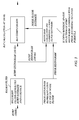
- the first block 51 i.e. power estimation block, applies a so called Kalman filter for estimation of certain power quantities that are needed by subsequent processing blocks.
- the block 51 receives a number of inputs 61A-E comprising the measured received total wideband power (RTWP) 61A, measured code power to interference ratio (C/I) of channel i 61B, beta factors for channel i 61C, number of codes for channel i 61D. corresponding code power to interference ratio commanded by a fast power control loop 61E, and provides outputs comprising power estimates 62A, 62B and corresponding standard deviations 63A, 63B.
- the output 62A is the estimate of a power quantity being the sum of neighbor cell WCDMA interference power, in-band non-WCDMA interference power and thermal noise floor power, and the output 63A is the estimated received total wideband power and the output 63B is the corresponding variance.
- the variances of said power quantities define estimated PDF:s of said power quantities (usually Gaussian in a preferred embodiment). Since the outputs are from the Kalman filter arrangement, these parameters are the only ones needed to define the estimated Gaussian distributions that are produced by the filter. Thus, enough information is given to define the entire probability distribution information of the power estimates.
- the scope of the present invention focuses on problems associated with this block 51.
- the second block 52 applies Bayesian estimation techniques in order to compute a conditional probability density function of the minimum of one of the above mentioned power quantities.
- the minimum also accounts (by Bayesian methods) for the prior distribution of the thermal noise power floor, thereby improving the average performance of the estimation, when evaluated over an ensemble of RBSs.
- the actual value of the noise floor can also be calculated by a calculation of the mean value of the estimated conditional probability distribution function.
- the block 52 receives the power estimate 62A and the corresponding standard deviations 62B as inputs, and provides an output 64 comprising the estimated probability distribution of an extreme value, typically the minimum, of P Estimate E + N + Noise , which is an estimate of the sum of neighbor cell interference power, external inband interference power and thermal noise power.
- Parameters 66 giving information about a prior expected probability distribution of the noise floor power is provided to the conditional probability distribution estimation block 52, in order to achieve an optimal estimation.
- the third block 53 performs soft noise rise estimation by a calculation of the conditional probability distribution of the quotient of the momentary estimated wide band power probability distribution (from block 52), and the conditional probability distribution of the noise power floor.
- the noise rise estimate is computed as a conditional mean. The details are omitted here.
- the most complicated setup of the previously described Kalman filter block 51 estimates the time variable powers of each power controlled channel of the cell, in order to allow a removal of own cell power before the noise floor power is estimated by the following block 52.
- the intention is that this reduction of interference, as seen by the thermal noise floor estimation step in block 52, should improve the accuracy of the overall estimator.
- a problem that immediately arises is that at least one state needs to be reserved for each channel, said state modelling the momentary channel power. Since the computational complexity of a general Kalman filter varies as the number of states raised to the third power, the consequence of the above is an unacceptably high computational complexity.
- Kalman filtering method reduces the computational complexity by the introduction of an approximate block structure in several steps in the Kalman filter algorithm.
- the end achievement is a reduction of the computational complexity to the number of states raised to the second power. This represents a substantial saving, a factor of 25 in a typical situation.
- a modified version of the previously described possible method discloses using a simplified soft solution. Only the RTWP is measured and a simplified algorithm for RoT estimation is applied. The simplified algorithm accordingly applies a simplified, one-dimensional Kalman filter for estimation of the RTWP and the corresponding variance. The reason why this filtering step is used is that the subsequent (still soft) processing blocks require probability distributions as input. These are best generated by a Kalman filter in the first processing block, corresponding to block 51 of the previously described method.
- the thermal noise power floor is estimated with the complete soft algorithm, as described with reference to Fig. 2 . Contrary to that previously described possible method, an (optimal) estimated value of the thermal noise power floor is calculated. Finally, the last processing block divides the estimated RTWP by the value of the thermal noise power floor, to obtain an estimate of the RoT. Note that this final step is not performed by a soft algorithm.
- a soft solution based on a single received wideband power (RTWP) measurement is used.
- the RTWP is measured and a simplified algorithm for RoT estimation is applied.
- An alternative variant relating to the second block 52 depicted in Fig. 2 discloses a recursive formulation of a key equation and reduces the memory consumption of the noise floor estimation block to less than 1 percent of previous requirements. This enables the execution of 1000+ parallel instances of the soft noise rise estimation algorithm in the RNC.
- the problem typically manifests itself in the second noise power floor estimation block 52 of the RoT estimator.
- Said second block 52 updates the probability distribution function of the minimum of several estimated probability distribution functions (PDF) of said estimated power quantities.
- PDF is represented as a histogram on a discretized power range or grid, typically between -120 dBm and -70 dBm. In order to avoid an excessive number of power grid points, the power grid is logarithmically distributed.
- Second problem increased computational complexity for overestimated prior noise floor information
- the basic idea of the present invention is to provide a suitable modification of the Kalman filter of block 51 of the RoT estimation algorithm, such that the key estimated covariance of certain estimated power quantities used by subsequent algorithmic steps, follow the measured mean power level.
- the covariance should be lower for power quantity levels that are lower than the nominal values used for tuning.
- the problem is solved by an explicit inclusion of a scaling of covariances e.g. the assumed measurement noise covariance and system noise covariance, or a pre-computed covariance.
- the scaling is typically the same for these two quantities. It is typically selected as the squared mean signal power level.
- the present invention comprises measuring S0 one or more samples of the received total wideband power (RTWP) and estimating S1 a probability distribution or probability density function (PDF) for at least one power quantity or power measure based on the measured RTWP. Subsequently, a mean or average power level is estimated S2 for the at least one power quantity, and finally the width of the estimated probability density is adapted S3 based on the estimated mean power level. Thereby a probability density function of a noise floor measure that is discretized on a grid is provided.
- RWP received total wideband power
- PDF probability distribution or probability density function
- a general extended Kalman filter formulation is used here. This is achieved by a treatment of a general state space model for description of the powers that affect the cell load.
- x ( t ) is a state vector consisting of various powers of relevance to a specific cell
- u ( t ) is an input vector consisting of certain power reference values and commands
- y ( t ) is an output vector consisting of the power measurements performed in the cell (e.g. the received total wideband power, RTWP)
- w ( t ) is the so called systems noise that represent the model error
- e ( t ) denotes the measurement error.
- the matrix A ( t ) is the system matrix describing the dynamic modes
- the matrix B ( t ) is the input gain matrix
- the vector c ( x ( t )) is the, possibly nonlinear, measurement vector which is a function of the states of the system.
- t represents the time and T represents the sampling period.
- Equations (2) The quantities introduced by the filter iterations of Equations (2) are as follows.
- t - T ) denotes the state prediction, based on data up to time t-T
- t ) denotes the filter update, based on data up to time t
- t - T ) denotes the covariance matrix of the state prediction, based on data up to time t-T
- t ) denotes the covariance matrix of the filter update, based on data up to time t .
- C ( t ) denotes the linearized measurement matrix (linearization around most current state prediction)
- K f ( t ) denotes the time variable Kalman gain matrix
- R 2 ( t ) denotes the measurement covariance matrix
- R 1 ( t ) denotes the system noise covariance matrix. It can be noted that R 1 ( t ) and R 2 ( t ) are often used as tuning variables of the filter. In principle the bandwidth of the filter is controlled by the matrix quotient of R 1 ( t ) and R 2 ( t ).
- ⁇ 2 corresponds to the mean squared power of a suitable power quantity, divided by the mean squared power of the same suitable power quantity at the nominal power level where R 1 ( t ) and R 2 ( t ) are tuned.
- the (extended) Kalman filter is run as usual, together with a scale factor estimation) and corresponding online correction to (2).
- the scaling parameter or scaling factor ⁇ (t) of the present invention can be estimated or determined in different ways, an embodiment of estimating or generating a scale parameter or factor will be described in more detail below.
- a typical approach would, according to a specific embodiment, be to estimate the scale factor by applying a recursive averaging filter to a suitable measured power quantity. If this is done in the linear domain, poor performance can result though. This is due to the very large dynamic range variations of up to 50 dB that may occur.
- the recursive averaging filter has a time constant corresponding to 1000 power samples.
- a sudden increase of the power level with e.g. 30 dB means that the latest power sample would dominate over the state of the filter, causing convergence to the new level 30 dB above the lower level within a few power samples.
- a remedy for the above situation is to perform the averaging of the present invention in the logarithmic domain, i.e. apply the recursive averaging filter to values expressed in dBW or dBm.
- x ( t ) is a measured power quantity in the linear domain
- x log ( t ) is the corresponding value in the logarithmic domain
- x log ( t ) is the logarithmic mean power value of the recursive filter at time t
- x nominal is the nominal value of the power level (used for tuning) in the linear domain.
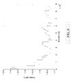
- FIG. 7 illustrates the measured total received wideband power (RTWP)
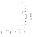
- Fig. 8 illustrates the estimated noise power floor without the present invention
- Fig. 9 illustrates the estimated noise power floor based on the present invention.
- the true noise power level is about -116.0 dBm, while the algorithm is tuned for a nominal level of -104 dBm.
- the algorithm without scaling delivers a noise floor about 1 dB too low, as compared to the algorithm with scaling that is almost on target.
- a 1 dB error means that an equivalent margin needs to be introduced e.g. in the admission control or enhanced uplink functions. This directly translates to a corresponding capacity loss (in this case about 5 voice calls).
- a wireless communications system 70 comprises a Universal mobile telecommunication system Terrestrial Radio Access Network (UTRAN) 71.
- a mobile terminal 25 is in radio contact with a RBS 20 in the UTRAN 71.
- the RBS 20 is controlled by a Radio Network Controller (RNC) 72, which in turn is connected to a Mobile services Switching Centre/Visitor Location Register (MSC/VLR) 74 and a Serving General packet radio system Support Node (SGSN) 75 of a core network CN 73.
- RNC Radio Network Controller
- MSC/VLR Mobile services Switching Centre/Visitor Location Register
- SGSN Serving General packet radio system Support Node
- the RBS 20 comprises means for obtaining measurements 80 of samples of at least the received total wideband power, means for estimating 81 a probability distribution of a first power quantity based on the measured total wideband power.
- the RBS 20 further comprises means for estimating 82 a mean power level for the first power quantity, and means for adapting 83 a width of the estimated probability distribution, to enable a subsequent calculation of a probability density function of a noise floor measure that is discretized on a grid.
- system further comprises an estimator unit for estimating or determining a scaling parameter ⁇ (t) to be supplied as an input parameter to the adaptation unit 83.
- the different means 80-83 can according to further embodiments be located within the RBS 20, as discussed above, or the RNC 72 or a mobile or user terminal 25. In the latter case, the invention concerns downlink noise floor estimation. This is indicated by the dashed boxes in the RNC 72 and the user terminal 25.
- the RNC 22 can according to known measures comprise means 84 for admission control.
- the means 84 for admission control comprises preferably functionality for enhanced uplink control, and is connected to the RBS 20 for information exchange, in particular concerning noise rise estimates.
Claims (22)
- Verfahren zum verbesserten Schätzen eines Leistungspegels von sanftem Rauschen in einem drahtlosen Code-Teilungs-Mehrfachzugriff-Kommunikationssystem, wobei das Verfahren umfasst:Messen (S0) von Proben zumindest einer empfangenen Gesamtbreitbandleistung,Schätzen (S1) einer Wahrscheinlichkeitsverteilung für eine erste Leistungsmenge anhand zumindest der gemessenen empfangenen Gesamtbreitbandleistung,Schätzen (S2) einer mittleren Leistungshöhe für die erste Leistungsmenge,Anpassen (S3) einer Breite der Wahrscheinlichkeitsverteilung auf Basis zumindest der geschätzten mittleren Leistungshöhe, wobei das Anpassen das Bestimmen eines Skalierungsparameters α(t) auf Basis der geschätzten mittleren Leistungshöhe umfasst,Berechnen einer konditionalen Wahrscheinlichkeitsverteilung für ein Minimum der ersten Leistungsmenge auf Basis der breitenangepassten Wahrscheinlichkeitsverteilung, wobei die konditionale Wahrscheinlichkeitsverteilung als Histogramm auf einem logarithmisch verteilten Leistungsgitter dargestellt ist, undBerechnen eines Schätzwerts der Leistung eines sanften Rauschens als Mittelwert der konditionalen Wahrscheinlichkeitsverteilung.
- Verfahren nach Anspruch 1, wobei der Anpassschritt (S3) eine Breite der Wahrscheinlichkeitsverteilung der ersten Leistungsmenge bereitstellt, die der Diskretisierungsdichte des Gitters entspricht.
- Verfahren nach Anspruch 1, wobei der Anpassschritt das Skalieren zumindest einer Kovarianz für die erste Leistungsmenge auf Basis des Skalierungsparameters umfasst.
- Verfahren nach Anspruch 3, wobei die zumindest eine Kovarianz eine geschätzte Kovarianz ist.
- Verfahren nach Anspruch 3, wobei die zumindest eine Kovarianz eine angenommene Messungsrauschen-Kovarianz und eine Systemrauschen-Kovarianz umfasst.
- Verfahren nach Anspruch 5, wobei beide Kovarianzen mit dem gleichen Skalierungsparameter skaliert werden.
- Verfahren nach Anspruch 1, wobei der Anpassschritt das Skalieren einer vorberechneten Kovarianz umfasst, wobei das Skalieren auf dem Skalierungsparameter basiert.
- Verfahren nach Anspruch 1, wobei das Skalieren auf Basis des Skalierungsparameters im Quadrat α2(t) durchgeführt wird.
- Verfahren nach Anspruch 1, wobei der Skalierungsparameter durch Mitteln über ein gleitendes Fenster bestimmt wird.
- Verfahren nach Anspruch 3, wobei der Skalierungsparameter α(t) wie folgt bestimmt wird:


x log(t) der logarithmische Leistungsmittelwert des rekursiven Filters zu einem Zeitpunkt t ist und xnominal der Nominalwert der Leistungshöhe in der linearen Domäne ist. - Verfahren nach Anspruch 3, wobei das Skalieren der zumindest einen Kovarianz wie folgt durchgeführt wird:


- Verfahren nach Anspruch 4, wobei das Skalieren wie folgt durchgeführt wird:

- Verfahren nach Anspruch 1, wobei die Breite der Wahrscheinlichkeitsverteilung die volle Halbwertsbreite (Full Width at Half Maximum) einer Gaußschen Verteilung ist.
- Knoten in einem drahtlosen Code-Teilungs-Mehrfachzugriff-Kommunikationssystem, wobei der Knoten umfasst:ein Mittel (80) zum Messen von Proben zumindest einer empfangenen Gesamtbreitbandleistung,ein Mittel (81) zum Schätzen einer Wahrscheinlichkeitsverteilung für eine erste Leistungsmenge anhand zumindest der gemessenen empfangenen Gesamtbreitbandleistung,ein Mittel (82) zum Schätzen einer mittleren Leistungshöhe für die erste Leistungsmenge,ein Mittel (83) zum Anpassen einer Breite der Wahrscheinlichkeitsverteilung auf Basis zumindest der geschätzten mittleren Leistungshöhe, wobei das Anpassen das Bestimmen eines Skalierungsparameters α(t) auf Basis der geschätzten mittleren Leistungshöhe umfasst,ein Mittel zum Berechnen einer konditionalen Wahrscheinlichkeitsverteilung für ein Minimum der ersten Leistungsmenge auf Basis der breitenangepassten Wahrscheinlichkeitsverteilung, wobei die konditionale Wahrscheinlichkeitsverteilung als Histogramm auf einem logarithmisch verteilten Leistungsgitter dargestellt ist, undein Mittel zum Berechnen eines Schätzwerts der Leistung eines sanften Rauschens als Mittelwert der konditionalen Wahrscheinlichkeitsverteilung.
- Knoten nach Anspruch 15, wobei das Anpassmittel (83) so ausgelegt ist, dass es eine Breite der Wahrscheinlichkeitsverteilung der ersten Leistungsmenge bereitstellt, die der Diskretisierungsdichte des Gitters entspricht.
- Knoten nach Anspruch 14, wobei das Anpassmittel (83) so ausgelegt ist, dass es zumindest eine Kovarianz für die erste Leistungsmenge auf Basis des Skalierungsparameters skaliert.
- Knoten nach Anspruch 16, wobei die zumindest eine Kovarianz eine geschätzte Kovarianz ist.
- Knoten nach Anspruch 16, wobei die zumindest eine Kovarianz eine angenommene Messungsrauschen-Kovarianz und eine Systemrauschen-Kovarianz umfasst.
- Knoten nach Anspruch 18, wobei beide Kovarianzen mit dem gleichen Skalierungsparameter skaliert werden.
- Knoten nach Anspruch 14, wobei das Anpassmittel (83) so ausgelegt ist, dass es eine vorberechnete Kovarianz skaliert, wobei das Skalieren auf dem Skalierungsparameter basiert.
- Knoten nach Anspruch 14, wobei das Skalieren auf Basis des Skalierungsparameters im Quadrat α2(t) durchgeführt wird.
- Knoten nach Anspruch 14, wobei der Skalierungsparameter durch Mittel über ein gleitendes Fenster bestimmt wird.
Applications Claiming Priority (1)
| Application Number | Priority Date | Filing Date | Title |
|---|---|---|---|
| PCT/SE2006/050388 WO2008041895A1 (en) | 2006-10-06 | 2006-10-06 | Method and arrangement for noise floor estimation |
Publications (3)
| Publication Number | Publication Date |
|---|---|
| EP2082504A1 EP2082504A1 (de) | 2009-07-29 |
| EP2082504A4 EP2082504A4 (de) | 2013-05-01 |
| EP2082504B1 true EP2082504B1 (de) | 2016-03-16 |
Family
ID=39268678
Family Applications (1)
| Application Number | Title | Priority Date | Filing Date |
|---|---|---|---|
| EP06799848.4A Not-in-force EP2082504B1 (de) | 2006-10-06 | 2006-10-06 | Verfahren und anordnung zur schätzung des grundrauschens |
Country Status (4)
| Country | Link |
|---|---|
| US (1) | US8665854B2 (de) |
| EP (1) | EP2082504B1 (de) |
| CN (1) | CN101523775B (de) |
| WO (1) | WO2008041895A1 (de) |
Families Citing this family (6)
| Publication number | Priority date | Publication date | Assignee | Title |
|---|---|---|---|---|
| CN101523775B (zh) * | 2006-10-06 | 2012-04-11 | 艾利森电话股份有限公司 | 用于改进的噪声基底估计的方法和设备 |
| WO2013043093A1 (en) | 2011-09-23 | 2013-03-28 | Telefonaktiebolaget L M Ericsson (Publ) | A radio network node, a controlling radio network node, and methods therein for enabling management of radio resources in a radio communications network |
| CN103052097B (zh) * | 2011-10-13 | 2018-07-20 | 南京中兴新软件有限责任公司 | 一种确定无线接入网络中参考rtwp的方法及其设备 |
| US9491715B2 (en) | 2012-05-23 | 2016-11-08 | Telefonaktiebolaget Lm Ericsson (Publ) | Thermal noise power floor estimation |
| US8886240B2 (en) * | 2012-07-17 | 2014-11-11 | Spectrum Bridge, Inc. | System and method for assessing noise floor data using radio blocking performance |
| US10955541B2 (en) * | 2017-08-29 | 2021-03-23 | Veoneer Us, Inc. | Apparatus and method for RF interference avoidance in an automotive detection system |
Family Cites Families (20)
| Publication number | Priority date | Publication date | Assignee | Title |
|---|---|---|---|---|
| US6628956B2 (en) * | 1999-03-15 | 2003-09-30 | Telefonaktiebolaget Lm Ericsson (Publ) | Adaptive power control in a radio communications systems |
| US6775544B2 (en) * | 1999-06-03 | 2004-08-10 | At&T Wireless Services, Inc. | Automatic diagnostic for detection of interference in wireless communication system |
| KR100609128B1 (ko) * | 1999-07-12 | 2006-08-04 | 에스케이 텔레콤주식회사 | 이동 통신 시스템의 통화 품질 측정 장치 및 방법 |
| GB0003369D0 (en) * | 2000-02-14 | 2000-04-05 | Nokia Networks Oy | Radio resource management in a communication system |
| US7339950B2 (en) * | 2001-06-29 | 2008-03-04 | Nokia Corporation | Allocation of radio resources to radio bearers |
| US7483711B2 (en) * | 2002-10-24 | 2009-01-27 | Bbn Technologies Corp | Spectrum-adaptive networking |
| KR100987275B1 (ko) * | 2003-02-14 | 2010-10-12 | 삼성전자주식회사 | 이동통신 시스템에서 열잡음 전력 측정 장치 및 방법 |
| US7397842B2 (en) * | 2003-09-26 | 2008-07-08 | Telefonaktiebolaget Lm Ericsson (Publ) | Method and apparatus for combining weight computation in a DS-CDMA RAKE receiver |
| KR100754384B1 (ko) * | 2003-10-13 | 2007-08-31 | 삼성전자주식회사 | 잡음에 강인한 화자위치 추정방법 및 장치와 이를 이용한카메라 제어시스템 |
| US7305056B2 (en) * | 2003-11-18 | 2007-12-04 | Ibiquity Digital Corporation | Coherent tracking for FM in-band on-channel receivers |
| ES2312821T3 (es) * | 2003-11-28 | 2009-03-01 | Telecom Italia S.P.A. | Procedimiento y dispositivo para la evaluacion del rendimiento de una red de telefonia movil. |
| US20060067383A1 (en) * | 2004-09-29 | 2006-03-30 | Carmela Cozzo | Parameter estimate initialization using interpolation |
| US7256733B2 (en) * | 2004-10-21 | 2007-08-14 | Qualcomm Incorporated | Method and system for positioning signal acquisition assistance window evaluation |
| US7848743B2 (en) * | 2005-01-21 | 2010-12-07 | Telefonaktiebolaget Lm Ericsson (Publ) | Methods and devices for uplink load estimation |
| US7577456B2 (en) * | 2005-02-28 | 2009-08-18 | Telefonaktiebolaget Lm Ericsson (Publ) | Using uplink relative path gain related measurements to support uplink resource management |
| EP1946455A4 (de) * | 2005-11-11 | 2012-06-06 | Ericsson Telefon Ab L M | Verringerung der komplexität bei der leistungsschätzung |
| US20070155395A1 (en) * | 2005-12-29 | 2007-07-05 | Nandu Gopalakrishnan | Scheduling mobile users based on cell load |
| JP4903863B2 (ja) * | 2006-07-05 | 2012-03-28 | テレフオンアクチーボラゲット エル エム エリクソン(パブル) | ノイズフロア推定のための方法及び装置 |
| CN101523775B (zh) * | 2006-10-06 | 2012-04-11 | 艾利森电话股份有限公司 | 用于改进的噪声基底估计的方法和设备 |
| EP2198540B1 (de) * | 2007-09-19 | 2020-02-12 | Telefonaktiebolaget LM Ericsson (publ) | Verfahren und anordnungen zur geräuschanstiegsschätzung |
-
2006
- 2006-10-06 CN CN200680056041.6A patent/CN101523775B/zh not_active Expired - Fee Related
- 2006-10-06 US US12/444,527 patent/US8665854B2/en not_active Expired - Fee Related
- 2006-10-06 EP EP06799848.4A patent/EP2082504B1/de not_active Not-in-force
- 2006-10-06 WO PCT/SE2006/050388 patent/WO2008041895A1/en active Application Filing
Also Published As
| Publication number | Publication date |
|---|---|
| CN101523775A (zh) | 2009-09-02 |
| US8665854B2 (en) | 2014-03-04 |
| EP2082504A1 (de) | 2009-07-29 |
| EP2082504A4 (de) | 2013-05-01 |
| US20100091753A1 (en) | 2010-04-15 |
| WO2008041895A1 (en) | 2008-04-10 |
| CN101523775B (zh) | 2012-04-11 |
Similar Documents
| Publication | Publication Date | Title |
|---|---|---|
| EP2067284B1 (de) | Verfahren und anordnungen zur speichereffizienten schätzung des rauschanstieges | |
| EP2005624B1 (de) | Verfahren und anordnung zur geräuschanstiegsschätzung | |
| EP1847045B1 (de) | Verfahren und einrichtungen zur aufwärtsstreckenlast-schätzung | |
| EP2109947B1 (de) | Lastschätzung unter verwendung der eingeplanten auswärtsstreckenleistung | |
| JP4903863B2 (ja) | ノイズフロア推定のための方法及び装置 | |
| EP1917725B1 (de) | Verfahren und anordnung zur geräuschanstiegsschätzung | |
| EP2198540B1 (de) | Verfahren und anordnungen zur geräuschanstiegsschätzung | |
| EP2082504B1 (de) | Verfahren und anordnung zur schätzung des grundrauschens | |
| EP2853049B1 (de) | Schätzung von thermischem grundrauschen | |
| EP2510630B1 (de) | Lastschätzung in der drahtlosen kommunikation | |
| EP2976921B1 (de) | Störungsschätzung und vorrichtungen dafür | |
| US9332507B2 (en) | Thermal noise floor estimation robustness via multi-carrier combining |
Legal Events
| Date | Code | Title | Description |
|---|---|---|---|
| PUAI | Public reference made under article 153(3) epc to a published international application that has entered the european phase |
Free format text: ORIGINAL CODE: 0009012 |
|
| 17P | Request for examination filed |
Effective date: 20090504 |
|
| AK | Designated contracting states |
Kind code of ref document: A1 Designated state(s): AT BE BG CH CY CZ DE DK EE ES FI FR GB GR HU IE IS IT LI LT LU LV MC NL PL PT RO SE SI SK TR |
|
| DAX | Request for extension of the european patent (deleted) | ||
| A4 | Supplementary search report drawn up and despatched |
Effective date: 20130405 |
|
| RIC1 | Information provided on ipc code assigned before grant |
Ipc: H04B 17/00 20060101AFI20130328BHEP |
|
| 17Q | First examination report despatched |
Effective date: 20130506 |
|
| REG | Reference to a national code |
Ref country code: DE Ref legal event code: R079 Ref document number: 602006048278 Country of ref document: DE Free format text: PREVIOUS MAIN CLASS: H04B0017000000 Ipc: H04B0017260000 |
|
| GRAP | Despatch of communication of intention to grant a patent |
Free format text: ORIGINAL CODE: EPIDOSNIGR1 |
|
| RIC1 | Information provided on ipc code assigned before grant |
Ipc: H04B 17/318 20150101ALN20151005BHEP Ipc: H04B 17/345 20150101ALI20151005BHEP Ipc: H04B 17/26 20150101AFI20151005BHEP |
|
| INTG | Intention to grant announced |
Effective date: 20151021 |
|
| RAP1 | Party data changed (applicant data changed or rights of an application transferred) |
Owner name: TELEFONAKTIEBOLAGET L M ERICSSON (PUBL) |
|
| GRAS | Grant fee paid |
Free format text: ORIGINAL CODE: EPIDOSNIGR3 |
|
| GRAA | (expected) grant |
Free format text: ORIGINAL CODE: 0009210 |
|
| AK | Designated contracting states |
Kind code of ref document: B1 Designated state(s): AT BE BG CH CY CZ DE DK EE ES FI FR GB GR HU IE IS IT LI LT LU LV MC NL PL PT RO SE SI SK TR |
|
| REG | Reference to a national code |
Ref country code: GB Ref legal event code: FG4D |
|
| REG | Reference to a national code |
Ref country code: CH Ref legal event code: EP |
|
| REG | Reference to a national code |
Ref country code: IE Ref legal event code: FG4D |
|
| REG | Reference to a national code |
Ref country code: AT Ref legal event code: REF Ref document number: 782005 Country of ref document: AT Kind code of ref document: T Effective date: 20160415 |
|
| REG | Reference to a national code |
Ref country code: DE Ref legal event code: R096 Ref document number: 602006048278 Country of ref document: DE |
|
| REG | Reference to a national code |
Ref country code: NL Ref legal event code: FP |
|
| REG | Reference to a national code |
Ref country code: LT Ref legal event code: MG4D |
|
| PG25 | Lapsed in a contracting state [announced via postgrant information from national office to epo] |
Ref country code: GR Free format text: LAPSE BECAUSE OF FAILURE TO SUBMIT A TRANSLATION OF THE DESCRIPTION OR TO PAY THE FEE WITHIN THE PRESCRIBED TIME-LIMIT Effective date: 20160617 Ref country code: FI Free format text: LAPSE BECAUSE OF FAILURE TO SUBMIT A TRANSLATION OF THE DESCRIPTION OR TO PAY THE FEE WITHIN THE PRESCRIBED TIME-LIMIT Effective date: 20160316 |
|
| REG | Reference to a national code |
Ref country code: AT Ref legal event code: MK05 Ref document number: 782005 Country of ref document: AT Kind code of ref document: T Effective date: 20160316 |
|
| PG25 | Lapsed in a contracting state [announced via postgrant information from national office to epo] |
Ref country code: SE Free format text: LAPSE BECAUSE OF FAILURE TO SUBMIT A TRANSLATION OF THE DESCRIPTION OR TO PAY THE FEE WITHIN THE PRESCRIBED TIME-LIMIT Effective date: 20160316 Ref country code: LT Free format text: LAPSE BECAUSE OF FAILURE TO SUBMIT A TRANSLATION OF THE DESCRIPTION OR TO PAY THE FEE WITHIN THE PRESCRIBED TIME-LIMIT Effective date: 20160316 Ref country code: LV Free format text: LAPSE BECAUSE OF FAILURE TO SUBMIT A TRANSLATION OF THE DESCRIPTION OR TO PAY THE FEE WITHIN THE PRESCRIBED TIME-LIMIT Effective date: 20160316 |
|
| PG25 | Lapsed in a contracting state [announced via postgrant information from national office to epo] |
Ref country code: EE Free format text: LAPSE BECAUSE OF FAILURE TO SUBMIT A TRANSLATION OF THE DESCRIPTION OR TO PAY THE FEE WITHIN THE PRESCRIBED TIME-LIMIT Effective date: 20160316 Ref country code: PL Free format text: LAPSE BECAUSE OF FAILURE TO SUBMIT A TRANSLATION OF THE DESCRIPTION OR TO PAY THE FEE WITHIN THE PRESCRIBED TIME-LIMIT Effective date: 20160316 Ref country code: IS Free format text: LAPSE BECAUSE OF FAILURE TO SUBMIT A TRANSLATION OF THE DESCRIPTION OR TO PAY THE FEE WITHIN THE PRESCRIBED TIME-LIMIT Effective date: 20160716 |
|
| PG25 | Lapsed in a contracting state [announced via postgrant information from national office to epo] |
Ref country code: CZ Free format text: LAPSE BECAUSE OF FAILURE TO SUBMIT A TRANSLATION OF THE DESCRIPTION OR TO PAY THE FEE WITHIN THE PRESCRIBED TIME-LIMIT Effective date: 20160316 Ref country code: RO Free format text: LAPSE BECAUSE OF FAILURE TO SUBMIT A TRANSLATION OF THE DESCRIPTION OR TO PAY THE FEE WITHIN THE PRESCRIBED TIME-LIMIT Effective date: 20160316 Ref country code: AT Free format text: LAPSE BECAUSE OF FAILURE TO SUBMIT A TRANSLATION OF THE DESCRIPTION OR TO PAY THE FEE WITHIN THE PRESCRIBED TIME-LIMIT Effective date: 20160316 Ref country code: ES Free format text: LAPSE BECAUSE OF FAILURE TO SUBMIT A TRANSLATION OF THE DESCRIPTION OR TO PAY THE FEE WITHIN THE PRESCRIBED TIME-LIMIT Effective date: 20160316 Ref country code: SK Free format text: LAPSE BECAUSE OF FAILURE TO SUBMIT A TRANSLATION OF THE DESCRIPTION OR TO PAY THE FEE WITHIN THE PRESCRIBED TIME-LIMIT Effective date: 20160316 Ref country code: PT Free format text: LAPSE BECAUSE OF FAILURE TO SUBMIT A TRANSLATION OF THE DESCRIPTION OR TO PAY THE FEE WITHIN THE PRESCRIBED TIME-LIMIT Effective date: 20160718 |
|
| REG | Reference to a national code |
Ref country code: DE Ref legal event code: R097 Ref document number: 602006048278 Country of ref document: DE |
|
| PG25 | Lapsed in a contracting state [announced via postgrant information from national office to epo] |
Ref country code: IT Free format text: LAPSE BECAUSE OF FAILURE TO SUBMIT A TRANSLATION OF THE DESCRIPTION OR TO PAY THE FEE WITHIN THE PRESCRIBED TIME-LIMIT Effective date: 20160316 Ref country code: BE Free format text: LAPSE BECAUSE OF FAILURE TO SUBMIT A TRANSLATION OF THE DESCRIPTION OR TO PAY THE FEE WITHIN THE PRESCRIBED TIME-LIMIT Effective date: 20160316 |
|
| PLBE | No opposition filed within time limit |
Free format text: ORIGINAL CODE: 0009261 |
|
| STAA | Information on the status of an ep patent application or granted ep patent |
Free format text: STATUS: NO OPPOSITION FILED WITHIN TIME LIMIT |
|
| PG25 | Lapsed in a contracting state [announced via postgrant information from national office to epo] |
Ref country code: DK Free format text: LAPSE BECAUSE OF FAILURE TO SUBMIT A TRANSLATION OF THE DESCRIPTION OR TO PAY THE FEE WITHIN THE PRESCRIBED TIME-LIMIT Effective date: 20160316 |
|
| 26N | No opposition filed |
Effective date: 20161219 |
|
| PG25 | Lapsed in a contracting state [announced via postgrant information from national office to epo] |
Ref country code: BG Free format text: LAPSE BECAUSE OF FAILURE TO SUBMIT A TRANSLATION OF THE DESCRIPTION OR TO PAY THE FEE WITHIN THE PRESCRIBED TIME-LIMIT Effective date: 20160616 |
|
| PG25 | Lapsed in a contracting state [announced via postgrant information from national office to epo] |
Ref country code: SI Free format text: LAPSE BECAUSE OF FAILURE TO SUBMIT A TRANSLATION OF THE DESCRIPTION OR TO PAY THE FEE WITHIN THE PRESCRIBED TIME-LIMIT Effective date: 20160316 |
|
| REG | Reference to a national code |
Ref country code: CH Ref legal event code: PL |
|
| REG | Reference to a national code |
Ref country code: IE Ref legal event code: MM4A |
|
| REG | Reference to a national code |
Ref country code: FR Ref legal event code: ST Effective date: 20170630 |
|
| PG25 | Lapsed in a contracting state [announced via postgrant information from national office to epo] |
Ref country code: FR Free format text: LAPSE BECAUSE OF NON-PAYMENT OF DUE FEES Effective date: 20161102 Ref country code: LI Free format text: LAPSE BECAUSE OF NON-PAYMENT OF DUE FEES Effective date: 20161031 Ref country code: CH Free format text: LAPSE BECAUSE OF NON-PAYMENT OF DUE FEES Effective date: 20161031 |
|
| PG25 | Lapsed in a contracting state [announced via postgrant information from national office to epo] |
Ref country code: LU Free format text: LAPSE BECAUSE OF NON-PAYMENT OF DUE FEES Effective date: 20161006 |
|
| PG25 | Lapsed in a contracting state [announced via postgrant information from national office to epo] |
Ref country code: IE Free format text: LAPSE BECAUSE OF NON-PAYMENT OF DUE FEES Effective date: 20161006 |
|
| PG25 | Lapsed in a contracting state [announced via postgrant information from national office to epo] |
Ref country code: CY Free format text: LAPSE BECAUSE OF FAILURE TO SUBMIT A TRANSLATION OF THE DESCRIPTION OR TO PAY THE FEE WITHIN THE PRESCRIBED TIME-LIMIT Effective date: 20160316 Ref country code: HU Free format text: LAPSE BECAUSE OF FAILURE TO SUBMIT A TRANSLATION OF THE DESCRIPTION OR TO PAY THE FEE WITHIN THE PRESCRIBED TIME-LIMIT; INVALID AB INITIO Effective date: 20061006 |
|
| PG25 | Lapsed in a contracting state [announced via postgrant information from national office to epo] |
Ref country code: TR Free format text: LAPSE BECAUSE OF FAILURE TO SUBMIT A TRANSLATION OF THE DESCRIPTION OR TO PAY THE FEE WITHIN THE PRESCRIBED TIME-LIMIT Effective date: 20160316 Ref country code: MC Free format text: LAPSE BECAUSE OF FAILURE TO SUBMIT A TRANSLATION OF THE DESCRIPTION OR TO PAY THE FEE WITHIN THE PRESCRIBED TIME-LIMIT Effective date: 20160316 |
|
| PGFP | Annual fee paid to national office [announced via postgrant information from national office to epo] |
Ref country code: NL Payment date: 20181026 Year of fee payment: 13 |
|
| PGFP | Annual fee paid to national office [announced via postgrant information from national office to epo] |
Ref country code: DE Payment date: 20181029 Year of fee payment: 13 |
|
| PGFP | Annual fee paid to national office [announced via postgrant information from national office to epo] |
Ref country code: GB Payment date: 20181029 Year of fee payment: 13 |
|
| REG | Reference to a national code |
Ref country code: DE Ref legal event code: R119 Ref document number: 602006048278 Country of ref document: DE |
|
| REG | Reference to a national code |
Ref country code: NL Ref legal event code: MM Effective date: 20191101 |
|
| PG25 | Lapsed in a contracting state [announced via postgrant information from national office to epo] |
Ref country code: DE Free format text: LAPSE BECAUSE OF NON-PAYMENT OF DUE FEES Effective date: 20200501 |
|
| PG25 | Lapsed in a contracting state [announced via postgrant information from national office to epo] |
Ref country code: NL Free format text: LAPSE BECAUSE OF NON-PAYMENT OF DUE FEES Effective date: 20191101 |
|
| GBPC | Gb: european patent ceased through non-payment of renewal fee |
Effective date: 20191006 |
|
| PG25 | Lapsed in a contracting state [announced via postgrant information from national office to epo] |
Ref country code: GB Free format text: LAPSE BECAUSE OF NON-PAYMENT OF DUE FEES Effective date: 20191006 |