EP2005624B1 - Verfahren und anordnung zur geräuschanstiegsschätzung - Google Patents
Verfahren und anordnung zur geräuschanstiegsschätzung Download PDFInfo
- Publication number
- EP2005624B1 EP2005624B1 EP06717145.4A EP06717145A EP2005624B1 EP 2005624 B1 EP2005624 B1 EP 2005624B1 EP 06717145 A EP06717145 A EP 06717145A EP 2005624 B1 EP2005624 B1 EP 2005624B1
- Authority
- EP
- European Patent Office
- Prior art keywords
- communication throughput
- site communication
- averaged
- total
- noise
- Prior art date
- Legal status (The legal status is an assumption and is not a legal conclusion. Google has not performed a legal analysis and makes no representation as to the accuracy of the status listed.)
- Not-in-force
Links
- 238000000034 method Methods 0.000 title claims description 35
- 238000004891 communication Methods 0.000 claims description 76
- 238000009826 distribution Methods 0.000 claims description 75
- 238000001914 filtration Methods 0.000 claims description 8
- 238000012935 Averaging Methods 0.000 claims description 7
- 230000008569 process Effects 0.000 claims description 6
- 230000001419 dependent effect Effects 0.000 claims description 5
- 238000012545 processing Methods 0.000 claims description 5
- 238000005259 measurement Methods 0.000 description 58
- 238000010586 diagram Methods 0.000 description 19
- 230000006870 function Effects 0.000 description 18
- 230000003750 conditioning effect Effects 0.000 description 9
- 230000000694 effects Effects 0.000 description 6
- 238000013459 approach Methods 0.000 description 5
- 238000004422 calculation algorithm Methods 0.000 description 5
- 230000002829 reductive effect Effects 0.000 description 5
- 238000011161 development Methods 0.000 description 4
- 238000004088 simulation Methods 0.000 description 4
- 201000001718 Roberts syndrome Diseases 0.000 description 3
- 208000012474 Roberts-SC phocomelia syndrome Diseases 0.000 description 3
- 230000008901 benefit Effects 0.000 description 3
- 230000001186 cumulative effect Effects 0.000 description 3
- 238000005315 distribution function Methods 0.000 description 3
- 230000014509 gene expression Effects 0.000 description 3
- 238000009499 grossing Methods 0.000 description 3
- 238000005001 rutherford backscattering spectroscopy Methods 0.000 description 3
- 238000004364 calculation method Methods 0.000 description 2
- 230000001413 cellular effect Effects 0.000 description 2
- 230000006872 improvement Effects 0.000 description 2
- 230000007774 longterm Effects 0.000 description 2
- 238000012986 modification Methods 0.000 description 2
- 230000004048 modification Effects 0.000 description 2
- 238000005070 sampling Methods 0.000 description 2
- 230000003190 augmentative effect Effects 0.000 description 1
- 238000013477 bayesian statistics method Methods 0.000 description 1
- 230000009286 beneficial effect Effects 0.000 description 1
- 230000010267 cellular communication Effects 0.000 description 1
- 230000007322 compensatory function Effects 0.000 description 1
- 238000007796 conventional method Methods 0.000 description 1
- 230000003247 decreasing effect Effects 0.000 description 1
- 238000009795 derivation Methods 0.000 description 1
- 238000013461 design Methods 0.000 description 1
- 238000005516 engineering process Methods 0.000 description 1
- 230000002349 favourable effect Effects 0.000 description 1
- 230000005484 gravity Effects 0.000 description 1
- 230000000670 limiting effect Effects 0.000 description 1
- 239000011159 matrix material Substances 0.000 description 1
- 238000010295 mobile communication Methods 0.000 description 1
- 230000008450 motivation Effects 0.000 description 1
- 238000007781 pre-processing Methods 0.000 description 1
- 230000005855 radiation Effects 0.000 description 1
- 230000004044 response Effects 0.000 description 1
- 230000000717 retained effect Effects 0.000 description 1
- 230000002441 reversible effect Effects 0.000 description 1
- 238000006467 substitution reaction Methods 0.000 description 1
Images


Classifications
-
- H—ELECTRICITY
- H04—ELECTRIC COMMUNICATION TECHNIQUE
- H04W—WIRELESS COMMUNICATION NETWORKS
- H04W52/00—Power management, e.g. TPC [Transmission Power Control], power saving or power classes
- H04W52/04—TPC
- H04W52/30—TPC using constraints in the total amount of available transmission power
- H04W52/34—TPC management, i.e. sharing limited amount of power among users or channels or data types, e.g. cell loading
-
- H—ELECTRICITY
- H04—ELECTRIC COMMUNICATION TECHNIQUE
- H04B—TRANSMISSION
- H04B17/00—Monitoring; Testing
- H04B17/30—Monitoring; Testing of propagation channels
- H04B17/309—Measuring or estimating channel quality parameters
- H04B17/345—Interference values
-
- H—ELECTRICITY
- H04—ELECTRIC COMMUNICATION TECHNIQUE
- H04W—WIRELESS COMMUNICATION NETWORKS
- H04W52/00—Power management, e.g. TPC [Transmission Power Control], power saving or power classes
- H04W52/04—TPC
- H04W52/18—TPC being performed according to specific parameters
- H04W52/22—TPC being performed according to specific parameters taking into account previous information or commands
- H04W52/225—Calculation of statistics, e.g. average, variance
-
- H—ELECTRICITY
- H04—ELECTRIC COMMUNICATION TECHNIQUE
- H04B—TRANSMISSION
- H04B17/00—Monitoring; Testing
- H04B17/30—Monitoring; Testing of propagation channels
- H04B17/382—Monitoring; Testing of propagation channels for resource allocation, admission control or handover
-
- H—ELECTRICITY
- H04—ELECTRIC COMMUNICATION TECHNIQUE
- H04W—WIRELESS COMMUNICATION NETWORKS
- H04W24/00—Supervisory, monitoring or testing arrangements
- H04W24/08—Testing, supervising or monitoring using real traffic
Definitions
- the present invention relates in general to methods and devices for estimation of load estimation in cellular communications systems, and in particular to noise-rise estimation in code division multiple access communications systems.
- WCDMA Wideband Code Division Multiple Access
- WCDMA Wideband Code Division Multiple Access
- a specific technical challenge in e.g. WCDMA and similar systems is the scheduling of enhanced uplink channels to time intervals where the interference conditions are favourable, and where there exist a sufficient capacity in the uplink of the cell in question to support enhanced uplink channels.
- existing users of the cell all contribute to the interference level in the uplink of WCDMA systems.
- terminals in neighbour cells also contribute to the same interference level. This is because all users and common channels of a cell transmit in the same frequency band when CDMA technology is used.
- the load of the cell is directly related to the interference level of the same cell.
- the load In order to retain stability of a cell, the load needs to be kept below a certain level. This follows since the majority of uplink user channels, at least in WCDMA, are subject to power control.
- This power control aims at keeping the received power level of each channel at a certain signal to interference ratio (SIR), in order to be able to meet specific service requirements.
- SIR signal to interference ratio
- This SIR level is normally such that the received powers in the radio base station (RBS) are several dBs below the interference level.
- RAKE-receivers then enhance each channel to a signal level where the transmitted bits can be further processed, e.g. by channel decoders and speech codecs that are located later in the signal processing chain.
- the RBS Since the RBS tries to keep each channel at its specific preferred SIR value, it may happen that an additional user, or bursty data traffic of an existing user, raises the interference level, thereby momentarily reducing the SIR for the other users.
- the response of the RBS is to command a power increase to all other users, something that increases the interference even more. Normally this process remains stable below a certain load level. In case a high capacity channel would suddenly appear, the raise in the interference becomes large and the risk for instability, a so called power rush, increases. It is thus a necessity to schedule high capacity uplink channels, like the enhanced uplink (E-UL) channel in WCDMA, so that one can insure that instability is avoided. In order to do so, the momentary load must be estimated in the RBS. This enables the assessment of the capacity margin that is left to the instability point.
- E-UL enhanced uplink
- the load of a cell in e.g. a CDMA system is usually referred to some quantity related to power, typically noise rise.
- a number of noise rise measures do exist. The most important one is perhaps the Rise over Thermal (RoT) that is defined as the quotient of the total interference of the cell and the thermal noise power floor of the receiver of the RBS.
- RoT Rise over Thermal
- Other measures include e.g. in-band non-WCDMA interference with respect to the thermal noise floor. Consequently, power quantities, such as total power level and noise floor (ideally thermal noise floor), have to be determined.
- Determinations of noise floor according to prior art is typically associated with relatively large uncertainties, which even may be in the same order of magnitude as the entire available capacity margin. This is particularly true when only measurements of total received power are available. It will thus be very difficult indeed to implement e.g. enhanced uplink channel functionality without improving the load estimation connected thereto.
- an equally important parameter that requires load estimation for its control is the coverage of the cell.
- the coverage is normally related to a specific service that needs to operate at a specific SIR to function normally.
- the uplink cell boundary is then defined by a terminal that operates at maximum output power.
- the maximum received channel power in the RBS is defined by the maximum power of the terminal and the pathloss to the digital receiver. Since the pathloss is a direct function of the distance between the terminal and the RBS, a maximum distance from the RBS results. This distance, taken in all directions from the RBS, defines the coverage.
- a general object of the present invention is to provide improved methods and arrangements for determining power-related quantities, e.g. load estimation.
- a further object of the present invention is to provide methods and arrangements giving opportunities for more accurate determination of power-related quantities.
- Yet a further object of the present invention is to provide methods and arrangements for improving noise rise estimations.
- a received total wideband power in a wireless communications system is measured a number of times during a time interval.
- a site communication throughput is determined and processed into a time averaged site communication throughput.
- a probability distribution for received total wideband power is estimated from the measured received total wideband power.
- An estimate of a noise floor measure is computed based on the probability distribution for received total wideband power and a noise rise measure is calculated based on the probability distribution for received total wideband power and the estimate of a noise floor measure.
- an adjustment of the noise rise measure is provided based on the averaged site communication throughput.
- the adjustment is performed by adjusting a variance of the probability distribution for received total wideband power based on the averaged site communication throughput.
- a noise contribution can be modelled as dependent on the averaged site communication throughput.
- Adjustments can also be performed on the noise rise measure according to a predetermined function of the averaged site communication throughput or on the estimate of a noise floor measure e.g. according to a predetermined function of said averaged site communication throughput.
- An advantage with the present invention is that the accuracy of thermal noise floor estimation is improved in the sense that an appropriate performance is extended to a wider operating load range while the complexity still is kept low.
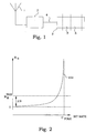
- FIG. 1 A typical signal chain of a RBS is depicted in Fig. 1 .
- a received wideband signal from an antenna 1 first passes an analogue signal conditioning chain 2, which consists of cables, filters etc. Variations among components together with temperature drift, render the scale factor of this part of the system to be undetermined with about 2-3 dBs, when the signal enters a receiver 3. This is discussed further below.
- the receiver 3 a number of operations take place.
- code power measurements i.e. powers of each individual channel/user of the cell, are made available at a stage 6.
- a reference point for estimated quantities is referred to as 4.
- the points in the chain where estimated quantities are valid, and where measurements are taken, are schematically shown in Fig. 1 .
- thermal noise floor power is affected by component uncertainties in the analogue receiver front end.
- the signal reference points are, by definition, at the antenna connector.
- the measurements are however obtained after the analogue signal conditioning chain, in the digital receiver. These uncertainties also possess a thermal drift.
- the analogue signal conditioning electronics chain does introduce a scale factor error of 2-3 dB between RBSs (batch) that is difficult to compensate for.
- the RTWP Receiveived Total Wideband Power
- the RTWP Receiveived Total Wideband Power
- the effect would be a noise rise estimate that is also wrong by 2-3 dB.
- the allowed noise rise interval in a WCDMA system is typically 0-10 dB, an error of 2-3 dB is not acceptable.
- P Total,Digital Receiver ( t ) and P Total,Antenna ( t ) are the total received powers at the digital receiver 3 and the antenna 1, respectively
- P N Digital ⁇ Re ⁇ ceiver and P N Antenna are the thermal noise level as measured at the digital receiver 3 and the antenna 1, respectively.
- (1) requires measurement of the noise floor P N Digital ⁇ Re ⁇ DC in the digital receiver. This is a major difficulty that is addressed by the present invention.
- Measurements of the total received wideband power are performed in the receiver. This measurement is denoted by P Total ( t ), where t denotes discrete time.
- the measurement rate is T -1 Hz .
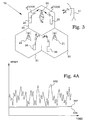
- Fig. 2 is a diagram illustrating these conditions.
- Noise rise N R defined as the ratio between a total power and the thermal noise level P N as measured at the antenna connector, also referred to as the noise floor, is a measure of the load.
- N R thr Above a noise rise threshold N R thr , the situation becomes unstable.
- a relation 100 between total bit rate and noise rise N R is known from the design of the control loops, and scheduling of additional channels can be performed once the instantaneous noise rise N R has been determined.
- the pole capacity, C pole denotes the maximum bitrate capacity in bits per second.
- a typical difference ⁇ N between the threshold N R thr and the level defined by the thermal noise level P N is typically about 7-10 dB.
- the noise floor or thermal noise level P N is not readily available. For instance, since scale factor uncertainties in the receiver may be as large as 2-3 dB as discussed above, a large part of the available margin is affected by such introduced uncertainties.
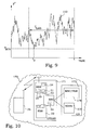
- Fig. 3 illustrates the contributions to power measurements in connection with an RBS 20.
- the RBS 20 is associated with a cell 30.
- a number of mobile terminals 25 are present, which communicates with the RBS 20 over different links, each contributing to the total received power by P i Code t .
- the cell 30 has a number of neighbouring cells 31 within the same WCDMA system, each associated with a RBS 21.
- the neighbouring cells also comprise mobile terminals 26.
- the mobile terminals 26 emit radio frequency power and the sum of all such contributions is denoted by P N .
- the P N term arises from the receiver itself.
- thermal noise floor is not always the sought quantity.
- constant in-band interference significantly affects the receiver of the RBS.
- These constant interferers do not affect the stability discussed above, they rather appear as an increased noise temperature, i.e. an increased thermal noise floor.
- one alternative is to use costly and individual determination of the thermal noise floor of each RBS in the field, in order to achieve a high enough load estimation performance.
- the establishment of the default value for the thermal noise power floor, as seen in the digital receiver requires reference measurements performed over a large number of RBSs either in the factory or in the field. Both alternatives are costly and need to be repeated as soon as the hardware changes.
- Another approach is to provide an estimation of the thermal noise power floor.
- One principle for estimation of the thermal noise power floor is to estimate it as a minimum of a measured or estimated power quantity comprising the thermal noise floor. This minimum is typically computed over a pre-determined interval of time. If no code power measurements are available, the power in question is the total received wideband power.
- One approach would therefore be to calculate the noise rise as a division of the momentary total received wideband power with an established thermal noise floor power estimated as a minimum of the total received wideband power over a pre-determined interval of time.
- a recursive estimation filter can be applied to the series of measurements, providing estimates of the received total wideband power, as well as the variance thereof.
- the thermal noise power floor may then be estimated by soft algorithms, described in detail further below.
- Fig. 4B illustrates a measurement situation where the average throughput through the RBS in question is larger than in Fig. 4A . This is obvious since it can easily be seen that the average received total wideband power is notably increased. Another effect will also be that when the long term average load of the system increases, then normally the neighbour cell interference increases. The consequence is that the likelihood of total power measurements or estimations in the vicinity of the true noise floor 106 will be reduced. Measurement results very close to the true noise floor will also be less probable.
- a site communication throughput is measured at a number of occasions in parallel with the measurements of received total wideband power.
- This site communication throughput is a measure of the number of bits per second that is transmitted through a base station or cell.
- the site communication throughput can be defined for uplink communication, downlink communication or for both uplink and downlink communication.
- the measured site communication throughput is processed into a time averaged site communication throughput, in order to remove fast fluctuations.
- Such an averaging processing could be a recursive filter having a certain time constant or, equivalently, bandwidth. An example of such an averaging is given further below.
- the noise rise measure is according to the present invention adjusted based on this time averaged site communication throughput. As described more in detail in the different embodiments below, such an adjustment can be performed at different stages in the determination of the noise rise.
- One alternative is to adjust the final noise rise measure with a certain factor according to a predetermined function of time averaged site communication throughput.
- Another alternative is to adjust the noise floor estimate before calculating the noise rise measure.
- the variance of the estimated received total wideband power can be adjusted based on the time averaged site communication throughput, which will counteract the decreased probability of low received total wideband power measurements somewhat. In other words, the estimated probability distribution will be modified. It is also an alternative to let the time averaged site communication throughput already influence the model used for estimating the received total wideband power.
- one choice is to increase the magnitude of the introduced measurement noise function as a function of the time averaged site communication throughput.
- Fig. 5 illustrates a curve 108, which indicates an expected behaviour of a ratio between an estimated noise rise without throughput compensation and a "true" noise rise.
- the noise rise will generally be underestimated.
- the adjusted noise rise 114 should follow the "true" noise rise. This can be performed in the dB-domain, as illustrated in Fig. 5 , whereby the adjustment becomes an addition. It can also be performed in the linear domain, whereby the adjustment becomes a multiplication.
- the idea is simple. However, the shape of the curve 108 may be difficult to measure of theoretically predict for each individual base station, as well as for different types of traffic.
- Fig. 6 illustrates a curve 120, which indicates an expected behaviour of a ratio between an estimated noise floor without throughput compensation and a "true" noise floor.
- the noise floor will generally be overestimated.
- the adjusted noise floor 124 should follow the "true" noise floor. This can be performed in the dB-domain, as illustrated in Fig. 6 , whereby the adjustment becomes a subtraction. It can also be performed in the linear domain, whereby the adjustment becomes a division.
- the idea is simple. However, also the shape of this curve 120 may be difficult to measure of theoretically predict for each individual base station, as well as for different types of traffic.
- Fig. 7 illustrates a block diagram of an embodiment of such a setup.
- a noise rise estimation arrangement 50 comprises three main blocks 60, 70, 80.
- a Kalman filter arrangement receives inputs 61, in the present embodiment the measured received total wideband power RTWP.
- Mathematical details of preferred embodiment are disclosed in Appendix A.
- the output 69 from the power estimation block 60 is the estimate of the received total wideband power RTWP and the corresponding variance. Since the outputs are from the Kalman filter arrangement, these parameter are the only ones needed to define the estimated Gaussian distribution that is produced by the filter. Thus, enough information is given to define the entire probability distribution information of the RTWP estimate.
- the filter details are discussed more in detail further below.
- conditional probability distribution estimation block 70 an arrangement based on Bayesian statistics receives the RTWP estimate and the corresponding standard deviation 69 as inputs, and provides an output 79 comprising parameters associated with a noise floor power. This may be a single value of a noise floor power or parameters of an estimated probability distribution of a noise floor power. Prior known parameters representing histograms of probability density functions of noise floor is stored in a storage 71 providing information 72 about a prior expected probability distribution of the noise floor power to the conditional probability distribution estimation block 70, in order to achieve an optimal estimation.
- the soft noise power floor estimation algorithm operates by removing portions of the prior probability distribution of the thermal noise power floor, from above, by application of a calculation of the probability distribution of the minimum of the estimated total power. This moves the centre of gravity of the prior distribution towards lower values, thereby reducing the optimal estimate of the thermal noise power floor.
- the amount that is cut away is determined by the probability distributions of the estimated total power that fall within a pre-determined, sparsely sampled sliding window. Then a total power probability distribution with a larger variance will obviously cut away a larger portion of the prior probability distribution than one with the same mean value and a smaller variance. The reason is that the probability distribution function with the larger variance extends further into the region of nonzero support of the prior probability distribution.
- noise rise estimation block 80 the estimated probability distribution of the noise floor 79 and the RTWP estimate and the corresponding standard deviation 69 are received as inputs, and provides primarily an output 81 comprising a noise rise value.
- the blocks 60, 70 and 80 are preferably integrated into one processor. However, any arrangements comprising, but not limited to, different distributed solutions are also possible to use, where the processor means comprising the blocks 60, 70 and 80 may be considered as a distributed processor means.
- a block diagram of an embodiment of a power estimation block 60 is illustrated.
- the RTWP measurements 61 are provided to a recursive filter, in which an estimate of the RTWP and a corresponding variance are determined and output 65 to a probability density function adjuster 67.
- the site communication throughput measures 62 are provided to a time averager 64, which provides a time averaged site communication throughput value 66 to the probability density function adjuster 67.
- the variance of the RTWP is adjusted in the probability density function adjuster 67 according to a predefined function and the RTWP and the adjusted corresponding variance is provided as the output 69 from the power estimation block 60.
- the time averaging of the site communication throughput can be performed in many different ways, which as such are known in prior art. Sliding window techniques as well as recursive approaches are feasible.
- V n -1 and V n are averaged site communication throughput at two consecutive measurement occasions
- T V is the time between two consecutive measurement occasions
- T A is a time constant
- V n is the site communication throughput at measurement occasion n .
- the averaging can be arranged in many other manners.
- a block scheme of another embodiment of a power estimation block 60 is illustrated.
- the RTWP measurements 61 are provided to an estimator 63, in this embodiment a recursive filter, in which an estimate of the RTWP and a corresponding variance are determined and used as output 69 from the power estimation block 60.
- the site communication throughput measures 62 are provided to a time averager 64, for instance arranged according to the above described principles.
- the time averaged site communication throughput value 66 is provided to the recursive filter influencing the filter operation.
- the averaged site communication throughput is arranged to influence the measurement noise covariance entered into the filter model.
- the sought compensation is introduced by a functional dependence of average throughput in the quotient between the measurement noise covariance and the system noise covariance, of the Kalman filer.
- a suitable functional dependence can be determined from system simulations.
- the variance of the RTWP will thereby implicitly be adjusted.
- P Measurement Total 10 - 3 ⁇ 10 P Measurement Total t / 10
- P Measurement Total is the measured total wideband power in dBm
- P Linear Total is the measured total wideband power in Watts
- k 1 is a first constant that may be determined experimentally
- k 2 is a second constant that may be determined experimentally
- F V is a compensatory function "that achieves the purpose of the invention”
- r is the applied system noise variance of the Kalman filter
- r Measurement is the applied measurement noise variance of the Kalman filter.
- a wireless communications system 170 comprises a Universal mobile telecommunication system Terrestrial Radio Access Network (UTRAN) 171.
- UTRAN Universal mobile telecommunication system Terrestrial Radio Access Network
- a mobile terminal 25 is in radio contact with a RBS 20 in the UTRAN 171.
- UTRAN Universal mobile telecommunication system Terrestrial Radio Access Network
- the RBS 20 is controlled by a Radio Network Controller (RNC) 172, which in turn is connected to a Mobile services Switching Centre/Visitor Location Register (MSC/VLR) 174 and a Serving General packet radio system Support Node (SGSN) 175 of a core network CN 173.
- RNC Radio Network Controller
- MSC/VLR Mobile services Switching Centre/Visitor Location Register
- SGSN Serving General packet radio system Support Node
- the RBS 20 comprises a power sensing arrangement 51, typically an antenna and front end electronics, for measuring instantaneous received total wideband power and a noise rise estimation arrangement 50.
- These means 51 and 50 can be implemented as separate units or as at least partly integrated units.
- the RBS 20 may itself comprise means 54 for internally determining the site communication throughput, illustrated with broken lines in Fig. 10 .
- the RNC 172 may comprise the means 54 for internally determining the site communication throughput, also illustrated with broken lines in Fig. 10 , and the RBS 20 receives information of the site communication throughput via the connection 53.
- the means 54 and the connection 53 are thus two embodiments of means for obtaining a site communication throughput.
- the means for obtaining a site communication throughput 53, 54 is connected to the noise rise estimation arrangement 50 to provide necessary site communication throughput data.
- the noise rise estimation arrangement 50 can thereby determine an improved appropriate noise rise estimation.
- the means 50-51 are instead comprised in the RNC 172. At least a part of the actual measuring remains typically in the RBS 20 due to the proximity of the antenna. Also other alternative configurations of the means 50, 51, 53 and 54 are possible, as anyone skilled in the art realises.
- Fig. 11A illustrates a flow diagram of main steps of an embodiment of a method according to the present invention.
- the procedure starts in step 200.
- step 202 a number of measurements of total received wideband power is made.
- step 204 a number of measurements of site communication throughput is made.
- the measured site communication throughput is processed into a time averaged site communication throughput in step 206.
- step 208 a filter model is adjusted based on the averaged site communication throughput.
- a probability distribution for received total wideband power is estimated from at least the measured received total wideband power using the adjusted filter model.
- step 214 an estimate of a noise floor measure is computed based on the probability distribution for received total wideband power.
- step 218, a noise rise measure is calculated based at least on the probability distribution for received total wideband power and the estimate of a noise floor measure.
- the procedure ends in step 299.
- Fig. 11B illustrates a flow diagram of main steps of another embodiment of a method according to the present invention. Steps 200, 202, 204, and 206 are the same as in Fig. 11B .
- a probability distribution for received total wideband power is estimated from at least the measured received total wideband power.
- the variance of the estimated probability distribution for received total wideband power is adjusted based on the averaged site communication throughput.
- an estimate of a noise floor measure is computed based on the adjusted probability distribution for received total wideband power.
- a noise rise measure is calculated based at least on the adjusted probability distribution for received total wideband power and the estimate of a noise floor measure. The procedure ends in step 299.
- Fig. 11C illustrates a flow diagram of main steps of yet another embodiment of a method according to the present invention.
- Steps 200, 202, 204, 206 and 210 are the same as in Fig. 11B .
- step 214 an estimate of a noise floor measure is computed based on the probability distribution for received total wideband power.
- step 216 the estimate of a noise floor measure is adjusted based on the averaged site communication throughput.
- a noise rise measure is calculated based at least on the probability distribution for received total wideband power and the adjusted estimate of a noise floor measure. The procedure ends in step 299.
- Fig. 11D illustrates a flow diagram of main steps of yet another embodiment of a method according to the present invention. Steps 200, 202, 204, 206, 210 and 214 are the same as in Fig. 11C .
- a noise rise measure is calculated based at least on the probability distribution for received total wideband power and the estimate of a noise floor measure.
- the noise rise measure is adjusted based on the averaged site communication throughput. The procedure ends in step 299.
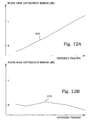
- Fig. 12A noise floor estimation errors as obtained by a determination of minimum of RTWP in a receiver without any throughput compensation are illustrated for different offered traffic situations. The traffic was in this simulation speech traffic.
- Fig. 12B corresponding noise floor estimation errors are illustrated, when the principles according to the present invention are applied.
- a proposed algorithm for the case where the total RTWP is measured is a prediction-update filter, where the subscripts distinguish between the prediction and the update steps.
- the updating gain K Update ( t ) is as seen above computed from the model parameter r Measurement and from a predicted covariance P Pr ⁇ ediction Cov ⁇ t - T min obtained at the previous sampling instance.
- the total wideband power updated with the latest measurement P Update Total t is then computed, using the prediction P Pr ⁇ ediction Total t and the new measurement P Measurement Total t .
- the next step is to compute the updated covariance P Update Cov t from the predicted covariance and from r Measurement .
- new values of P Pr ⁇ ediction Total t and P Pr ediction Cov t are calculated and the time is stepped.
- T min denotes the sampling period.
- Probability distributions Consider two events A and B, with probability distributions f A ( x ) and f B ( y ), respectively. Then the joint probability distribution of A and B is denoted f A,B ( x,y ).
- the events and the conditioning are expressed by subscripts, whereas the independent variables appear within the parentheses. This notation is used only when probability distributions and cumulative probability distributions are used. When state estimates and covariances, e.g. of the Kalman filter, are referred to, the conditioning may also appear within parentheses.
- conditional probability distributions f A
- a ( y ) are defined by: f A , B x y f A
- B x ⁇ f B y f B
- the Kalman filter or Kalman smoother estimate of P Total ( t' ) is denoted by: x ⁇ P Total Kalman t ⁇
- y s s ⁇ - ⁇ , t x ⁇ P Total Kalman ⁇ t ⁇
- conditional distributions are, under mild conditions, all Gaussian sufficient statistics, i.e. only second order properties are needed in order to describe the conditional probability distributions. This is reflected in the conditioning in the last expression of (A3).
- the conditional distributions follow as: f x ⁇ P Total Kalman t ⁇
- Fig. 9 illustrates a diagram showing time variations 110 of a total received wideband power P Total ( t ).
- the total received wideband power presents high values.
- the total received wideband power becomes small, indicating that many of the usual contributions to the measured power are absent.
- smoother estimates are theoretically required as inputs to the conditional probability estimation algorithm for the minimum power that operates over the time interval ⁇ t - T Lag , t ⁇ .
- the smoother estimates should also be calculated using all data in ⁇ t - T Lag , t ⁇ .
- these smoother estimates are typically computed using only a short snapshot of data around the selected smoothing time instance.
- conditional distribution of the minimum value can now be written as follows (cf. (B5)): f min ⁇ x P Total 0 t ⁇ t ⁇ ⁇ t - T Lag , t
- Bayes rule and the definition of conditional mean, for probability distributions, are used extensively.
- the last step can again be easily verified by drawing circle diagrams.
- the first factor of the numerator of (B9) is a prior and hence the conditioning disappears.
- the second factor of the numerator will be further expanded below, whereas the last factor of the numerator and the denominator can be treated as parts of a normalizing constant.
- Equation (B10) states that the conditional pdf (probability distribution function) is given as the product of a prior (initial value) and a measurement dependant factor.
- the prior is supplied by the user and should reflect the prior uncertainty regarding P N . Note that whenever the sliding window is moved and a new estimate is calculated, the same prior is again applied. The prior is hence not updated in the basic setting of the estimator.
- the final step in the derivation of the first factor of the distribution function is to differentiate (B11), obtaining: f min ⁇ x P Total 0 t ⁇ t ⁇ ⁇ t - T Lag , t
- Y t x dF min ⁇ x P Total 0 t ⁇ t ⁇ ⁇ t - T Lag , t
- Y t x dx ⁇ t ⁇ ⁇ t - T Lag , t f ⁇ ⁇ x t ⁇
- a mean value computation is performed on the output distribution.
Claims (18)
- Verfahren zur Rauschanstiegsschätzung in einem drahtlosen Kommunikationssystem (170), die folgenden Schritte umfassend:vielmaliges Messen (202) der empfangenen Breitband-Gesamtleistung;vielmaliges Messen (204) des Standort-Kommunikationsdurchsatzes;Verarbeiten (206) des gemessenen Standort-Kommunikationsdurchsatzes zu einem zeitgemittelten Standort-Kommunikationsdurchsatz;Schätzen (210) einer Wahrscheinlichkeitsverteilung für die empfangene Breitband-Gesamtleistung anhand mindestens der gemessenen empfangenen Breitband-Gesamtleistung;Errechnen (214) einer Schätzgröße eines Grundrauschmaßes auf der Grundlage der Wahrscheinlichkeitsverteilung für die empfangene Breitband-Gesamtleistung und gespeicherter Information über eine vorher erwartete Wahrscheinlichkeitsverteilung der Grundrauschens;Berechnen (218) eines Rauschanstiegsmaßes auf der Grundlage zumindest der Wahrscheinlichkeitsverteilung für die empfangene Breitband-Gesamtleistung und der Schätzgröße eines Grundrauschmaßes; undErbringen (208, 212, 216, 220) einer Korrektur des Rauschanstiegsmaßes auf der Grundlage des gemittelten Standort-Kommunikationsdurchsatzes.
- Verfahren nach Anspruch 1, dadurch gekennzeichnet, dass der Schritt des Erbringens einer Korrektur durch Korrigieren (220) des Rauschanstiegsmaßes auf der Grundlage des gemittelten Standort-Kommunikationsdurchsatzes erfolgt.
- Verfahren nach Anspruch 2, dadurch gekennzeichnet, dass das Rauschanstiegsmaß gemäß einer vorbestimmten Funktion des gemittelten Standort-Kommunikationsdurchsatzes korrigiert wird.
- Verfahren nach Anspruch 1, dadurch gekennzeichnet, dass der Schritt des Erbringens einer Korrektur durch Korrigieren (216) der Schätzgröße eines Grundrauschmaßes auf der Grundlage des gemittelten Standort-Kommunikationsdurchsatzes erfolgt.
- Verfahren nach Anspruch 4, dadurch gekennzeichnet, dass der Schritt des Erbringens einer Korrektur durch Korrigieren (216) der Schätzgröße eines Grundrauschmaßes gemäß einer vorbestimmten Funktion des gemittelten Standort-Kommunikationsdurchsatzes erfolgt.
- Verfahren nach Anspruch 1, dadurch gekennzeichnet, dass der Schritt des Erbringens einer Korrektur durch Korrigieren (208, 212) einer Varianz der Wahrscheinlichkeitsverteilung für die empfangene Breitband-Gesamtleistung auf der Grundlage des gemittelten Standort-Kommunikationsdurchsatzes erfolgt.
- Verfahren nach einem der Ansprüche 1 bis 6, dadurch gekennzeichnet, dass der Schritt des Schätzens (210) einer Wahrscheinlichkeitsverteilung für die empfangene Breitband-Gesamtleistung durch einen Kalman-Filterprozess erfolgt.
- Verfahren nach Anspruch 6 oder 7, dadurch gekennzeichnet, dass der Schritt des Schätzens (210) einer Wahrscheinlichkeitsverteilung für die empfangene Breitband-Gesamtleistung ferner auf der Grundlage des gemittelten Standort-Kommunikationsdurchsatzes erfolgt.
- Verfahren nach Anspruch 8, dadurch gekennzeichnet, dass der Schritt des Schätzens (210) einer Wahrscheinlichkeitsverteilung für die empfangene Breitband-Gesamtleistung durch einen Kalman-Filterprozess erfolgt, bei dem ein Rauschanteil in Abhängigkeit von dem gemittelten Standort-Kommunikationsdurchsatz modelliert wird.
- Knoten (20,172) eines drahtlosen Kommunikationssystems (170), umfassend:eine Leistungserfassungsanordnung (51) zur Messung einer empfangenen Breitband-Gesamtleistung;ein Mittel (53, 54) zur Gewinnung eines Standort-Kommunikationsdurchsatzes;ein Mittelungsmittel (64) zur Verarbeitung des gemessenen Standort-Kommunikationsdurchsatzes zu einem zeitgemittelten Standort-Kommunikationsdurchsatz, das mit dem Mittel (53, 54) zur Gewinnung eines Standort-Kommunikationsdurchsatzes verbunden ist; undein Prozessormittel, das mit der Leistungserfassungsanordnung (51) verbunden ist und dafür eingerichtet ist, eine Wahrscheinlichkeitsverteilung für die empfangene Breitband-Gesamtleistung anhand mindestens der gemessenen empfangenen Breitband-Gesamtleistung zu schätzen;wobei das Prozessormittel ferner dafür eingerichtet ist, eine Schätzgröße eines Grundrauschmaßes auf der Grundlage der Wahrscheinlichkeitsverteilung für die empfangene Breitband-Gesamtleistung und gespeicherter Information über eine vorher erwartete Wahrscheinlichkeitsverteilung des Grundrauschens zu errechnen;wobei das Prozessormittel ferner dafür eingerichtet ist, das Rauschanstiegsmaß auf der Grundlage zumindest der Wahrscheinlichkeitsverteilung für die empfangene Breitband-Gesamtleistung und der Schätzgröße eines Grundrauschmaßes zu berechnen;wobei das Prozessormittel ferner mit dem Mittelungsmittel (64) verbunden ist, wodurch das Prozessormittel ferner dafür eingerichtet ist, eine Korrektur des Rauschanstiegsmaßes auf der Grundlage des gemittelten Standort-Kommunikationsdurchsatzes zu erbringen.
- Knoten nach Anspruch 10, dadurch gekennzeichnet, dass das Prozessormittel dafür eingerichtet ist, das Rauschanstiegsmaß auf der Grundlage des gemittelten Standort-Kommunikationsdurchsatzes zu korrigieren.
- Knoten nach Anspruch 11, dadurch gekennzeichnet, dass das Prozessormittel dafür eingerichtet ist, das Rauschanstiegsmaß gemäß einer vorbestimmten Funktion des gemittelten Standort-Kommunikationsdurchsatzes zu korrigieren.
- Knoten nach Anspruch 10, dadurch gekennzeichnet, dass das Prozessormittel dafür eingerichtet ist, die Schätzgröße eines Grundrauschmaßes auf der Grundlage des gemittelten Standort-Kommunikationsdurchsatzes zu korrigieren.
- Knoten nach Anspruch 13, dadurch gekennzeichnet, dass das Prozessormittel dafür eingerichtet ist, die Schätzgröße eines Grundrauschmaßes gemäß einer vorbestimmten Funktion des gemittelten Standort-Kommunikationsdurchsatzes zu korrigieren.
- Knoten nach Anspruch 10, dadurch gekennzeichnet, dass das Prozessormittel dafür eingerichtet ist, eine Varianz der Wahrscheinlichkeitsverteilung für die empfangene Breitband-Gesamtleistung auf der Grundlage des gemittelten Standort-Kommunikationsdurchsatzes zu korrigieren.
- Knoten nach einem der Ansprüche 10 bis 15, dadurch gekennzeichnet, dass das Prozessormittel dafür eingerichtet ist, die Wahrscheinlichkeitsverteilung für die empfangene Breitband-Gesamtleistung durch einen Kalman-Filterprozesses zu schätzen.
- Knoten nach Anspruch 15 oder 16, dadurch gekennzeichnet, dass das Prozessormittel dafür eingerichtet ist, die Wahrscheinlichkeitsverteilung für die empfangene Breitband-Gesamtleistung ferner auf der Grundlage des gemittelten Standort-Kommunikationsdurchsatzes zu schätzen.
- Knoten nach Anspruch 17, dadurch gekennzeichnet, dass das Prozessormittel dafür eingerichtet ist, die Wahrscheinlichkeitsverteilung für die empfangene Breitband-Gesamtleistung durch einen Kalman-Filterprozess zu schätzen, bei dem ein Rauschanteil in Abhängigkeit von dem gemittelten Standort-Kommunikationsdurchsatz modelliert wird.
Applications Claiming Priority (1)
| Application Number | Priority Date | Filing Date | Title |
|---|---|---|---|
| PCT/SE2006/050066 WO2007117188A1 (en) | 2006-04-10 | 2006-04-10 | Methods and arrangements for noise rise estimation |
Publications (3)
| Publication Number | Publication Date |
|---|---|
| EP2005624A1 EP2005624A1 (de) | 2008-12-24 |
| EP2005624A4 EP2005624A4 (de) | 2012-05-16 |
| EP2005624B1 true EP2005624B1 (de) | 2014-01-15 |
Family
ID=38581384
Family Applications (1)
| Application Number | Title | Priority Date | Filing Date |
|---|---|---|---|
| EP06717145.4A Not-in-force EP2005624B1 (de) | 2006-04-10 | 2006-04-10 | Verfahren und anordnung zur geräuschanstiegsschätzung |
Country Status (3)
| Country | Link |
|---|---|
| US (1) | US8170492B2 (de) |
| EP (1) | EP2005624B1 (de) |
| WO (1) | WO2007117188A1 (de) |
Families Citing this family (13)
| Publication number | Priority date | Publication date | Assignee | Title |
|---|---|---|---|---|
| US8218450B2 (en) * | 2007-05-24 | 2012-07-10 | Nec Corporation | Throughput estimation method and system |
| EP2198540B1 (de) * | 2007-09-19 | 2020-02-12 | Telefonaktiebolaget LM Ericsson (publ) | Verfahren und anordnungen zur geräuschanstiegsschätzung |
| US8264975B2 (en) * | 2008-02-20 | 2012-09-11 | Qualcomm Incorporated | FFT-based estimation of thermal noise and rise over thermal in a wireless communication system |
| EP2441176B1 (de) * | 2009-06-11 | 2012-10-17 | Telefonaktiebolaget LM Ericsson (publ) | Lastschätzung in störungsweissungssystemen |
| BR112012005157A2 (pt) * | 2009-09-08 | 2016-05-03 | Ericsson Telefon Ab L M | método e arranjo para estimativa de aumento de ruído em um sistema de comunicação sem fio, e, estação base |
| US9055500B2 (en) * | 2010-05-18 | 2015-06-09 | Telefonaktiebolaget L M Ericsson (Publ) | Load estimation in softer handover |
| CN102934478B (zh) * | 2010-06-10 | 2016-03-16 | 瑞典爱立信有限公司 | 频域预均衡系统中的负载估计 |
| WO2012074445A1 (en) | 2010-11-30 | 2012-06-07 | Telefonaktiebolaget L M Ericsson (Publ) | Method and device for noise floor estimation |
| US20130260746A1 (en) * | 2010-12-21 | 2013-10-03 | Telefonaktiebolaget L M Ericsson (Publ) | Radio base station, radio network controller and methods therein |
| US20130003543A1 (en) * | 2011-06-30 | 2013-01-03 | Avistar Communications Corporation | NEXT-GENERATION BANDWIDTH MANAGEMENT CONTROL SYSTEMS FOR MULTIPLE-SERVICE CALLS, SESSIONS, PACKET-LEVEL PROCESSES, AND QoS PARAMETERS - PART 1: STRUCTURAL AND FUNCTIONAL ARCHITECTURES |
| WO2013043093A1 (en) | 2011-09-23 | 2013-03-28 | Telefonaktiebolaget L M Ericsson (Publ) | A radio network node, a controlling radio network node, and methods therein for enabling management of radio resources in a radio communications network |
| CN103052097B (zh) * | 2011-10-13 | 2018-07-20 | 南京中兴新软件有限责任公司 | 一种确定无线接入网络中参考rtwp的方法及其设备 |
| US9007947B2 (en) * | 2013-02-25 | 2015-04-14 | Telefonaktiebolaget L M Ericsson (Publ) | Grant utilization based other cell interference estimation |
Family Cites Families (5)
| Publication number | Priority date | Publication date | Assignee | Title |
|---|---|---|---|---|
| US6775544B2 (en) * | 1999-06-03 | 2004-08-10 | At&T Wireless Services, Inc. | Automatic diagnostic for detection of interference in wireless communication system |
| US6539213B1 (en) * | 1999-06-14 | 2003-03-25 | Time Domain Corporation | System and method for impulse radio power control |
| KR100987275B1 (ko) | 2003-02-14 | 2010-10-12 | 삼성전자주식회사 | 이동통신 시스템에서 열잡음 전력 측정 장치 및 방법 |
| US7489901B2 (en) * | 2004-09-30 | 2009-02-10 | Alcatel-Lucent Usa Inc. | Method for dynamically estimating noise floor and rise over thermal (ROT) |
| US7848743B2 (en) | 2005-01-21 | 2010-12-07 | Telefonaktiebolaget Lm Ericsson (Publ) | Methods and devices for uplink load estimation |
-
2006
- 2006-04-10 EP EP06717145.4A patent/EP2005624B1/de not_active Not-in-force
- 2006-04-10 WO PCT/SE2006/050066 patent/WO2007117188A1/en active Application Filing
- 2006-04-10 US US12/296,751 patent/US8170492B2/en active Active
Also Published As
| Publication number | Publication date |
|---|---|
| US20090176455A1 (en) | 2009-07-09 |
| US8170492B2 (en) | 2012-05-01 |
| EP2005624A1 (de) | 2008-12-24 |
| EP2005624A4 (de) | 2012-05-16 |
| WO2007117188A1 (en) | 2007-10-18 |
Similar Documents
| Publication | Publication Date | Title |
|---|---|---|
| EP2005624B1 (de) | Verfahren und anordnung zur geräuschanstiegsschätzung | |
| EP2067284B1 (de) | Verfahren und anordnungen zur speichereffizienten schätzung des rauschanstieges | |
| EP1917725B1 (de) | Verfahren und anordnung zur geräuschanstiegsschätzung | |
| EP1847045B1 (de) | Verfahren und einrichtungen zur aufwärtsstreckenlast-schätzung | |
| US8175537B2 (en) | Method and arrangement for noise floor estimation | |
| US9071359B2 (en) | Method for noise floor and interference estimation | |
| EP2109947B1 (de) | Lastschätzung unter verwendung der eingeplanten auswärtsstreckenleistung | |
| EP2198540B1 (de) | Verfahren und anordnungen zur geräuschanstiegsschätzung | |
| US9124367B2 (en) | Methods and arrangements for memory-efficient estimation of noise floor | |
| EP2082504B1 (de) | Verfahren und anordnung zur schätzung des grundrauschens | |
| EP2510630B1 (de) | Lastschätzung in der drahtlosen kommunikation |
Legal Events
| Date | Code | Title | Description |
|---|---|---|---|
| PUAI | Public reference made under article 153(3) epc to a published international application that has entered the european phase |
Free format text: ORIGINAL CODE: 0009012 |
|
| 17P | Request for examination filed |
Effective date: 20080929 |
|
| AK | Designated contracting states |
Kind code of ref document: A1 Designated state(s): AT BE BG CH CY CZ DE DK EE ES FI FR GB GR HU IE IS IT LI LT LU LV MC NL PL PT RO SE SI SK TR |
|
| A4 | Supplementary search report drawn up and despatched |
Effective date: 20120416 |
|
| RIC1 | Information provided on ipc code assigned before grant |
Ipc: H04B 7/005 20060101ALI20120416BHEP Ipc: H04W 24/00 20090101ALI20120416BHEP Ipc: H04B 17/00 20060101AFI20120416BHEP |
|
| 17Q | First examination report despatched |
Effective date: 20120605 |
|
| DAX | Request for extension of the european patent (deleted) | ||
| GRAP | Despatch of communication of intention to grant a patent |
Free format text: ORIGINAL CODE: EPIDOSNIGR1 |
|
| RIC1 | Information provided on ipc code assigned before grant |
Ipc: H04W 52/22 20090101ALI20130705BHEP Ipc: H04B 17/00 20060101AFI20130705BHEP Ipc: H04W 24/08 20090101ALI20130705BHEP Ipc: H04W 52/34 20090101ALI20130705BHEP |
|
| INTG | Intention to grant announced |
Effective date: 20130815 |
|
| GRAS | Grant fee paid |
Free format text: ORIGINAL CODE: EPIDOSNIGR3 |
|
| GRAA | (expected) grant |
Free format text: ORIGINAL CODE: 0009210 |
|
| AK | Designated contracting states |
Kind code of ref document: B1 Designated state(s): AT BE BG CH CY CZ DE DK EE ES FI FR GB GR HU IE IS IT LI LT LU LV MC NL PL PT RO SE SI SK TR |
|
| REG | Reference to a national code |
Ref country code: CH Ref legal event code: EP Ref country code: GB Ref legal event code: FG4D |
|
| REG | Reference to a national code |
Ref country code: AT Ref legal event code: REF Ref document number: 650220 Country of ref document: AT Kind code of ref document: T Effective date: 20140215 |
|
| REG | Reference to a national code |
Ref country code: IE Ref legal event code: FG4D |
|
| REG | Reference to a national code |
Ref country code: DE Ref legal event code: R096 Ref document number: 602006040061 Country of ref document: DE Effective date: 20140227 |
|
| REG | Reference to a national code |
Ref country code: NL Ref legal event code: VDEP Effective date: 20140115 |
|
| REG | Reference to a national code |
Ref country code: AT Ref legal event code: MK05 Ref document number: 650220 Country of ref document: AT Kind code of ref document: T Effective date: 20140115 |
|
| REG | Reference to a national code |
Ref country code: LT Ref legal event code: MG4D |
|
| PG25 | Lapsed in a contracting state [announced via postgrant information from national office to epo] |
Ref country code: IS Free format text: LAPSE BECAUSE OF FAILURE TO SUBMIT A TRANSLATION OF THE DESCRIPTION OR TO PAY THE FEE WITHIN THE PRESCRIBED TIME-LIMIT Effective date: 20140515 Ref country code: LT Free format text: LAPSE BECAUSE OF FAILURE TO SUBMIT A TRANSLATION OF THE DESCRIPTION OR TO PAY THE FEE WITHIN THE PRESCRIBED TIME-LIMIT Effective date: 20140115 |
|
| PG25 | Lapsed in a contracting state [announced via postgrant information from national office to epo] |
Ref country code: AT Free format text: LAPSE BECAUSE OF FAILURE TO SUBMIT A TRANSLATION OF THE DESCRIPTION OR TO PAY THE FEE WITHIN THE PRESCRIBED TIME-LIMIT Effective date: 20140115 Ref country code: PT Free format text: LAPSE BECAUSE OF FAILURE TO SUBMIT A TRANSLATION OF THE DESCRIPTION OR TO PAY THE FEE WITHIN THE PRESCRIBED TIME-LIMIT Effective date: 20140515 Ref country code: NL Free format text: LAPSE BECAUSE OF FAILURE TO SUBMIT A TRANSLATION OF THE DESCRIPTION OR TO PAY THE FEE WITHIN THE PRESCRIBED TIME-LIMIT Effective date: 20140115 Ref country code: FI Free format text: LAPSE BECAUSE OF FAILURE TO SUBMIT A TRANSLATION OF THE DESCRIPTION OR TO PAY THE FEE WITHIN THE PRESCRIBED TIME-LIMIT Effective date: 20140115 Ref country code: CY Free format text: LAPSE BECAUSE OF FAILURE TO SUBMIT A TRANSLATION OF THE DESCRIPTION OR TO PAY THE FEE WITHIN THE PRESCRIBED TIME-LIMIT Effective date: 20140115 Ref country code: SE Free format text: LAPSE BECAUSE OF FAILURE TO SUBMIT A TRANSLATION OF THE DESCRIPTION OR TO PAY THE FEE WITHIN THE PRESCRIBED TIME-LIMIT Effective date: 20140115 Ref country code: ES Free format text: LAPSE BECAUSE OF FAILURE TO SUBMIT A TRANSLATION OF THE DESCRIPTION OR TO PAY THE FEE WITHIN THE PRESCRIBED TIME-LIMIT Effective date: 20140115 |
|
| PG25 | Lapsed in a contracting state [announced via postgrant information from national office to epo] |
Ref country code: LV Free format text: LAPSE BECAUSE OF FAILURE TO SUBMIT A TRANSLATION OF THE DESCRIPTION OR TO PAY THE FEE WITHIN THE PRESCRIBED TIME-LIMIT Effective date: 20140115 Ref country code: BE Free format text: LAPSE BECAUSE OF FAILURE TO SUBMIT A TRANSLATION OF THE DESCRIPTION OR TO PAY THE FEE WITHIN THE PRESCRIBED TIME-LIMIT Effective date: 20140115 |
|
| REG | Reference to a national code |
Ref country code: DE Ref legal event code: R097 Ref document number: 602006040061 Country of ref document: DE |
|
| PG25 | Lapsed in a contracting state [announced via postgrant information from national office to epo] |
Ref country code: CZ Free format text: LAPSE BECAUSE OF FAILURE TO SUBMIT A TRANSLATION OF THE DESCRIPTION OR TO PAY THE FEE WITHIN THE PRESCRIBED TIME-LIMIT Effective date: 20140115 Ref country code: DK Free format text: LAPSE BECAUSE OF FAILURE TO SUBMIT A TRANSLATION OF THE DESCRIPTION OR TO PAY THE FEE WITHIN THE PRESCRIBED TIME-LIMIT Effective date: 20140115 Ref country code: EE Free format text: LAPSE BECAUSE OF FAILURE TO SUBMIT A TRANSLATION OF THE DESCRIPTION OR TO PAY THE FEE WITHIN THE PRESCRIBED TIME-LIMIT Effective date: 20140115 Ref country code: RO Free format text: LAPSE BECAUSE OF FAILURE TO SUBMIT A TRANSLATION OF THE DESCRIPTION OR TO PAY THE FEE WITHIN THE PRESCRIBED TIME-LIMIT Effective date: 20140115 |
|
| PLBE | No opposition filed within time limit |
Free format text: ORIGINAL CODE: 0009261 |
|
| STAA | Information on the status of an ep patent application or granted ep patent |
Free format text: STATUS: NO OPPOSITION FILED WITHIN TIME LIMIT |
|
| PG25 | Lapsed in a contracting state [announced via postgrant information from national office to epo] |
Ref country code: MC Free format text: LAPSE BECAUSE OF FAILURE TO SUBMIT A TRANSLATION OF THE DESCRIPTION OR TO PAY THE FEE WITHIN THE PRESCRIBED TIME-LIMIT Effective date: 20140115 Ref country code: PL Free format text: LAPSE BECAUSE OF FAILURE TO SUBMIT A TRANSLATION OF THE DESCRIPTION OR TO PAY THE FEE WITHIN THE PRESCRIBED TIME-LIMIT Effective date: 20140115 Ref country code: SK Free format text: LAPSE BECAUSE OF FAILURE TO SUBMIT A TRANSLATION OF THE DESCRIPTION OR TO PAY THE FEE WITHIN THE PRESCRIBED TIME-LIMIT Effective date: 20140115 Ref country code: LU Free format text: LAPSE BECAUSE OF FAILURE TO SUBMIT A TRANSLATION OF THE DESCRIPTION OR TO PAY THE FEE WITHIN THE PRESCRIBED TIME-LIMIT Effective date: 20140410 |
|
| REG | Reference to a national code |
Ref country code: CH Ref legal event code: PL |
|
| 26N | No opposition filed |
Effective date: 20141016 |
|
| REG | Reference to a national code |
Ref country code: FR Ref legal event code: ST Effective date: 20141231 |
|
| REG | Reference to a national code |
Ref country code: IE Ref legal event code: MM4A |
|
| PG25 | Lapsed in a contracting state [announced via postgrant information from national office to epo] |
Ref country code: LI Free format text: LAPSE BECAUSE OF NON-PAYMENT OF DUE FEES Effective date: 20140430 Ref country code: CH Free format text: LAPSE BECAUSE OF NON-PAYMENT OF DUE FEES Effective date: 20140430 |
|
| REG | Reference to a national code |
Ref country code: DE Ref legal event code: R097 Ref document number: 602006040061 Country of ref document: DE Effective date: 20141016 |
|
| PG25 | Lapsed in a contracting state [announced via postgrant information from national office to epo] |
Ref country code: FR Free format text: LAPSE BECAUSE OF NON-PAYMENT OF DUE FEES Effective date: 20140430 |
|
| PG25 | Lapsed in a contracting state [announced via postgrant information from national office to epo] |
Ref country code: IE Free format text: LAPSE BECAUSE OF NON-PAYMENT OF DUE FEES Effective date: 20140410 |
|
| PG25 | Lapsed in a contracting state [announced via postgrant information from national office to epo] |
Ref country code: SI Free format text: LAPSE BECAUSE OF FAILURE TO SUBMIT A TRANSLATION OF THE DESCRIPTION OR TO PAY THE FEE WITHIN THE PRESCRIBED TIME-LIMIT Effective date: 20140115 |
|
| PG25 | Lapsed in a contracting state [announced via postgrant information from national office to epo] |
Ref country code: BG Free format text: LAPSE BECAUSE OF FAILURE TO SUBMIT A TRANSLATION OF THE DESCRIPTION OR TO PAY THE FEE WITHIN THE PRESCRIBED TIME-LIMIT Effective date: 20140115 |
|
| PG25 | Lapsed in a contracting state [announced via postgrant information from national office to epo] |
Ref country code: GR Free format text: LAPSE BECAUSE OF FAILURE TO SUBMIT A TRANSLATION OF THE DESCRIPTION OR TO PAY THE FEE WITHIN THE PRESCRIBED TIME-LIMIT Effective date: 20140416 Ref country code: IT Free format text: LAPSE BECAUSE OF FAILURE TO SUBMIT A TRANSLATION OF THE DESCRIPTION OR TO PAY THE FEE WITHIN THE PRESCRIBED TIME-LIMIT Effective date: 20140115 |
|
| PG25 | Lapsed in a contracting state [announced via postgrant information from national office to epo] |
Ref country code: TR Free format text: LAPSE BECAUSE OF FAILURE TO SUBMIT A TRANSLATION OF THE DESCRIPTION OR TO PAY THE FEE WITHIN THE PRESCRIBED TIME-LIMIT Effective date: 20140115 Ref country code: HU Free format text: LAPSE BECAUSE OF FAILURE TO SUBMIT A TRANSLATION OF THE DESCRIPTION OR TO PAY THE FEE WITHIN THE PRESCRIBED TIME-LIMIT; INVALID AB INITIO Effective date: 20060410 |
|
| PGFP | Annual fee paid to national office [announced via postgrant information from national office to epo] |
Ref country code: GB Payment date: 20190429 Year of fee payment: 14 |
|
| GBPC | Gb: european patent ceased through non-payment of renewal fee |
Effective date: 20200410 |
|
| PG25 | Lapsed in a contracting state [announced via postgrant information from national office to epo] |
Ref country code: GB Free format text: LAPSE BECAUSE OF NON-PAYMENT OF DUE FEES Effective date: 20200410 |
|
| PGFP | Annual fee paid to national office [announced via postgrant information from national office to epo] |
Ref country code: DE Payment date: 20220427 Year of fee payment: 17 |
|
| REG | Reference to a national code |
Ref country code: DE Ref legal event code: R119 Ref document number: 602006040061 Country of ref document: DE |
|
| PG25 | Lapsed in a contracting state [announced via postgrant information from national office to epo] |
Ref country code: DE Free format text: LAPSE BECAUSE OF NON-PAYMENT OF DUE FEES Effective date: 20231103 |