EP2081062A1 - Dual liquid crystal display (LCD) - Google Patents
Dual liquid crystal display (LCD) Download PDFInfo
- Publication number
- EP2081062A1 EP2081062A1 EP08171302A EP08171302A EP2081062A1 EP 2081062 A1 EP2081062 A1 EP 2081062A1 EP 08171302 A EP08171302 A EP 08171302A EP 08171302 A EP08171302 A EP 08171302A EP 2081062 A1 EP2081062 A1 EP 2081062A1
- Authority
- EP
- European Patent Office
- Prior art keywords
- lcd
- lcd panel
- substrate
- dual
- panel
- Prior art date
- Legal status (The legal status is an assumption and is not a legal conclusion. Google has not performed a legal analysis and makes no representation as to the accuracy of the status listed.)
- Granted
Links
Images


Classifications
-
- G—PHYSICS
- G02—OPTICS
- G02F—OPTICAL DEVICES OR ARRANGEMENTS FOR THE CONTROL OF LIGHT BY MODIFICATION OF THE OPTICAL PROPERTIES OF THE MEDIA OF THE ELEMENTS INVOLVED THEREIN; NON-LINEAR OPTICS; FREQUENCY-CHANGING OF LIGHT; OPTICAL LOGIC ELEMENTS; OPTICAL ANALOGUE/DIGITAL CONVERTERS
- G02F1/00—Devices or arrangements for the control of the intensity, colour, phase, polarisation or direction of light arriving from an independent light source, e.g. switching, gating or modulating; Non-linear optics
- G02F1/01—Devices or arrangements for the control of the intensity, colour, phase, polarisation or direction of light arriving from an independent light source, e.g. switching, gating or modulating; Non-linear optics for the control of the intensity, phase, polarisation or colour
- G02F1/13—Devices or arrangements for the control of the intensity, colour, phase, polarisation or direction of light arriving from an independent light source, e.g. switching, gating or modulating; Non-linear optics for the control of the intensity, phase, polarisation or colour based on liquid crystals, e.g. single liquid crystal display cells
- G02F1/133—Constructional arrangements; Operation of liquid crystal cells; Circuit arrangements
- G02F1/1333—Constructional arrangements; Manufacturing methods
-
- G—PHYSICS
- G02—OPTICS
- G02B—OPTICAL ELEMENTS, SYSTEMS OR APPARATUS
- G02B6/00—Light guides; Structural details of arrangements comprising light guides and other optical elements, e.g. couplings
- G02B6/0001—Light guides; Structural details of arrangements comprising light guides and other optical elements, e.g. couplings specially adapted for lighting devices or systems
- G02B6/0011—Light guides; Structural details of arrangements comprising light guides and other optical elements, e.g. couplings specially adapted for lighting devices or systems the light guides being planar or of plate-like form
- G02B6/0033—Means for improving the coupling-out of light from the light guide
- G02B6/0035—Means for improving the coupling-out of light from the light guide provided on the surface of the light guide or in the bulk of it
- G02B6/0045—Means for improving the coupling-out of light from the light guide provided on the surface of the light guide or in the bulk of it by shaping at least a portion of the light guide
-
- G—PHYSICS
- G02—OPTICS
- G02F—OPTICAL DEVICES OR ARRANGEMENTS FOR THE CONTROL OF LIGHT BY MODIFICATION OF THE OPTICAL PROPERTIES OF THE MEDIA OF THE ELEMENTS INVOLVED THEREIN; NON-LINEAR OPTICS; FREQUENCY-CHANGING OF LIGHT; OPTICAL LOGIC ELEMENTS; OPTICAL ANALOGUE/DIGITAL CONVERTERS
- G02F1/00—Devices or arrangements for the control of the intensity, colour, phase, polarisation or direction of light arriving from an independent light source, e.g. switching, gating or modulating; Non-linear optics
- G02F1/01—Devices or arrangements for the control of the intensity, colour, phase, polarisation or direction of light arriving from an independent light source, e.g. switching, gating or modulating; Non-linear optics for the control of the intensity, phase, polarisation or colour
- G02F1/13—Devices or arrangements for the control of the intensity, colour, phase, polarisation or direction of light arriving from an independent light source, e.g. switching, gating or modulating; Non-linear optics for the control of the intensity, phase, polarisation or colour based on liquid crystals, e.g. single liquid crystal display cells
- G02F1/133—Constructional arrangements; Operation of liquid crystal cells; Circuit arrangements
- G02F1/1333—Constructional arrangements; Manufacturing methods
- G02F1/1335—Structural association of cells with optical devices, e.g. polarisers or reflectors
-
- G—PHYSICS
- G02—OPTICS
- G02F—OPTICAL DEVICES OR ARRANGEMENTS FOR THE CONTROL OF LIGHT BY MODIFICATION OF THE OPTICAL PROPERTIES OF THE MEDIA OF THE ELEMENTS INVOLVED THEREIN; NON-LINEAR OPTICS; FREQUENCY-CHANGING OF LIGHT; OPTICAL LOGIC ELEMENTS; OPTICAL ANALOGUE/DIGITAL CONVERTERS
- G02F1/00—Devices or arrangements for the control of the intensity, colour, phase, polarisation or direction of light arriving from an independent light source, e.g. switching, gating or modulating; Non-linear optics
- G02F1/01—Devices or arrangements for the control of the intensity, colour, phase, polarisation or direction of light arriving from an independent light source, e.g. switching, gating or modulating; Non-linear optics for the control of the intensity, phase, polarisation or colour
- G02F1/13—Devices or arrangements for the control of the intensity, colour, phase, polarisation or direction of light arriving from an independent light source, e.g. switching, gating or modulating; Non-linear optics for the control of the intensity, phase, polarisation or colour based on liquid crystals, e.g. single liquid crystal display cells
- G02F1/133—Constructional arrangements; Operation of liquid crystal cells; Circuit arrangements
- G02F1/1333—Constructional arrangements; Manufacturing methods
- G02F1/133342—Constructional arrangements; Manufacturing methods for double-sided displays
Definitions
- the present invention relates to a Liquid Crystal Display (LCD), and more particularly, the present invention relates to a dual LCD including a transmissive first panel and a reflective second panel.
- LCD Liquid Crystal Display
- a Liquid Crystal Display is a flat panel display having advantages in that it is small, thin and has a low power consumption, and has been used in portable computers, such as notebook PCs, office automation equipment, audio/ video equipment, etc.
- An LCD displays a picture or an image by controlling an electric field to transmit or cut off the light, the electric field being applied to liquid crystal materials having dielectric anisotropy.
- An LCD uses external light from the outside without generating light by itself, unlike displays, such as Organic Light Emitting Displays (OLEDs) and Cathode Ray Tubes (CRTs), which generate light by themselves.
- OLEDs Organic Light Emitting Displays
- CRTs Cathode Ray Tubes
- LCDs are divided into transmissive and reflective LCDs depending on the manner of employing light.
- LCDs are divided into transmissive LCDs and reflective LCDs depending on whether they use a separate backlight or reflected external light as a light source.
- transflective LCD in which the transmissive LCD is combined with the reflective LCD.
- the dual LCD includes a main LCD panel and a sub LCD panel to display a picture on both sides thereof.
- conventional dual LCDs are provided with a backlight installed in each of the main LCD panels and the sub LCD panels so that the thickness and weight thereof are increased and the power consumption thereof is high.
- the present invention is designed to solve such drawbacks of the prior art, and it is therefore an object of the present invention is to provide a dual Liquid Crystal Display (LCD) including a transmissive first LCD panel for displaying an image on a first surface and a reflective second LCD panel for displaying an image on a second surface and being able to maximize slimness and cost saving effects by forming the first and second LCD panels on the same substrate.
- LCD Liquid Crystal Display
- One embodiment of the present invention is achieved by providing a dual LCD including: a first LCD panel and a second LCD panel formed on the same substrate, the first LCD panel displaying an image on a first surface thereof and the second LCD panel displaying an image on a second surface thereof; a backlight unit arranged on the bottom of the first LCD panel; and a housing anchoring the first and second LCD panels and the backlight unit and having an opening corresponding to an image-displaying surface of the second LCD panel.
- the first LCD panel is realized with a transmissive LCD panel
- the second LCD panel is realized with a reflective LCD panel.
- only a single backlight unit is provided within the dual LCD.
- the second surface of the second LCD panel is oriented opposite to the first surface of the first LCD panel, such that the image is displayed on opposite sides of the dual LCD.
- the first LCD panel and the second LCD panel are preferably arranged in a lateral direction such that they are provided side-by-side. A gap may be formed in between the first and the second LCD panel and their respective side surfaces.
- the same substrate on which the first and second display panels are formed comprises a first and a second substrate.
- the first and second LCD panels are respectively formed in different first and second regions of the first and second substrates forming the same substrate, a thin film transistor array and a transmissive electrode are formed in a region corresponding to the first region of the first substrate, a thin film transistor array and a reflective electrode are formed in a region corresponding to the second region of the first substrate, and a common electrode and a color filter pattern are respectively formed in first and second regions of the second substrate corresponding to the first and second regions of the first substrate.
- the first and second regions are arranged side-by-side or extending in a lateral direction of the dual LCD.
- a drive circuit unit to drive the first and second LCD panels is mounted on one side of the first substrate arranged outside the first and second regions, and a first polarizing plate and a second polarizing plate are respectively formed on the top and bottom of the first and second LCD panels.
- the single backlight unit includes: a power source and a light guide plate, arranged on the bottom of the first LCD panel; and an inclined portion formed on one side end of the light guide plate, the one side end of the light guide plate being an end portion of a light guide plate arranged in the remotest position away from the power source.
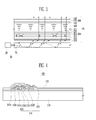
- FIG. 1 is a cross-sectional view of a configuration of a dual LCD according to one exemplary embodiment of the present invention.
- FIG. 2 is a cross-sectional view of the operation of the dual LCD of FIG. 1 .
- FIG. 3 is a cross-sectional view of a portion of the first LCD panel in the dual LCD of FIG. 1 .
- FIG. 4 is a cross-sectional view of a first substrate of FIG. 3 .
- FIG. 5 is a cross-sectional view of a portion of the second LCD panel in the dual LCD of FIG. 1 .
- FIG. 6 is a cross-sectional view of a first substrate of FIG. 5 .
- FIG. 1 is a cross-sectional view of a configuration of a dual LCD according to one exemplary embodiment of the present invention and FIG. 2 is a cross-sectional view of the operation of the dual LCD of FIG. 1 .
- the dual LCD 1 includes a first LCD panel 10, a second LCD panel 20, a backlight unit 30, and a housing 40.
- the first and second LCD panels 10 and 20 are formed on the same substrate, the first LCD panel 10 displaying an image on a first surface thereof, and the second LCD panel 20 displaying an image on a second surface thereof.
- the first and second surfaces may be provided on opposite sides of the dual LCD panel such that the image is display on opposite sides, e.g. a front and a back side, of the dual LCD panel.
- the first LCD panel 10 is realized with a transmissive LCD panel
- the second LCD panel 20 is realized with a reflective LCD panel.
- the first and second LCD panels 10 and 20 are formed using a pair of the same substrates.
- a Thin Film Transistor (TFT) array (not shown) and a transmissive electrode (not shown) are formed in a region corresponding to a first region of a first substrate 100, and a TFT array (not shown) and a reflective electrode (not shown) are formed on a region corresponding to a second region of the first substrate 100.
- a common electrode, i.e. common to the first and second LCD panel (not shown), and a color filter pattern (not shown) are formed respectively in first and second regions of a second substrate 200 corresponding to the first and second regions of the first substrate 100.
- a liquid crystal layer (not shown) is formed between the first substrate 100 and the second substrate 200.
- a first polarizing plate 120 and a second polarizing plate 220 are respectively formed on the top and bottom of the first and second LCD panels 10 and 20.
- the transmissive first LCD panel 10 is formed in the first regions of the first substrate 100 and the second substrate 200
- the reflective second LCD panel 20 is formed in the second regions of the first substrate 100 and the second substrate 200.
- a drive circuit unit 130 for driving the first and second LCD panels 10 and 20 is mounted on one side of the first substrate 100 and is arranged outside of the first LCD panel 10.
- the drive circuit 130 is arranged on that lateral side of the first LCD panel 10 on which the second LCD panel 20 is not arranged, i.e. the side opposite to the side where the second LCD panel 20 is arranged.
- the single backlight unit 30 includes a power source 32 and a light guide plate 34, as shown in FIG. 1 , arranged on the bottom of the first region, e.g., the first LCD panel 10.
- the single backlight unit 30 is provided for both the first and the second LCD panel 10, 20.
- the use of a first and second backlight unit for the first and second display panel 10, 20, respectively, is avoided, as explained in the following paragraphs.
- no additional second backlight unit 30 is arranged on the top of the LCD display panel, e.g. on the top of the second region.
- light generated by the power source 32 passes through a light guide plate 34, and enters a second polarizing plate 220 formed on the bottom of the first LCD panel 10.
- the first LCD panel 10 operates in a transmissive mode to display an image on an opposite surface, e.g., a first surface, of a surface that the light enters.
- one side end of the light guide plate 34 e.g., an end portion (A) of a light guide plate 34 positioned in the remotest position from the power source 32, is beveled at a predetermined angle, to allow some of the light transferred to the light guide plate 34 to enter the second polarizing plate 220 of the second LCD panel 20.
- the second LCD panel 20 may display the same image on both a surface (first surface) on which the first LCD panel 10 projects an image and on its opposite surface (second surface), e.g. a front and a back surface of the dual LCD panel.
- the housing 40 anchors the first and second LCD panels 10 and 20 and the backlight unit 30.
- An opening 42 is provided in the housing 40 to correspond to the second surface, e.g., an image-projected surface of the second LCD panel 20.
- the dual LCD panel may be realized using a pair of the same substrates. Therefore, the dual LCD may be desirably manufactured with a slim thickness since its dual structure may be achieved with the same thickness as conventional single-structured LCDs, and therefore, a considerable cost saving in both the material cost and processing cost may be expected.
- FIG. 3 is a cross-sectional view of a portion corresponding to the first LCD panel in the dual LCD of FIG. 1
- FIG. 4 is a cross-sectional view of the first substrate of FIG. 3 .
- a backlight unit 30 is arranged on the bottom of the first LCD panel 10, including a power source 32 for generating light and a light guide plate 34 for transmitting the light irradiated by the power source 32 into the first LCD panel 10.
- the first LCD panel 10 is composed of a first substrate 100; a second substrate 200 spaced apart from the first substrate 100 at a predetermined distance; and a liquid crystal layer 300 interposed between the first and second substrates 100 and 200. Also, a first polarizing plate 120 and a second polarizing plate 220 are formed respectively on the top and bottom of the first LCD panel 10.
- the first substrate 100 includes a transparent substrate 110; a Thin Film Transistor (hereinafter, referred to as a TFT) array 114 provided on the transparent substrate 110; and a pixel electrode 115 provided on the TFT array 114.
- a TFT Thin Film Transistor
- the TFT array 114 is composed of a TFT 112 and a first protective layer 113 for protecting the TFT 112.
- the TFT 112 is composed of a gate electrode 112a, a gate insulator 112b, an active layer 112c, an omic contact layer 112d, a source electrode 112e, and a drain electrode 112f.
- the gate electrode 112a is provided to correspond to the light-shielding layer 211 formed on the transparent substrate 210 of the second substrate 200.
- the gate insulator 112b is formed throughout the transparent substrate 110 on which the gate electrode 112a is formed.
- the active layer 112c and the omic contact layer 112d are provided on the gate insulator 112b to correspond to the gate electrode 112a.
- the source electrode 112e and the drain electrode 112f are provided on the omic contact layer 112d to be spaced apart from each other at a predetermined distance.
- Source and drain electrodes 112e and 112f as well as the gate electrode 112a are formed in a region on which the light-shielding layer 211 is formed. Therefore, the light-shielding layer 211 may prevent light entering the second substrate 200 from being reflected by the gate electrode 112a, the source electrode 112e and the drain electrode 112f.
- the first protective layer 113 provided on the TFT 112 partially exposes the drain electrode 112f of the TFT 112.
- the pixel electrode 115 is provided on the first protective layer 113 and the exposed drain electrode 112f, and thus electrically coupled to the drain electrode 112f.
- the pixel electrode 115 is composed of a transmissive electrode made of ITO or IZO.
- a light-shielding layer 211 and a color filter layer 212 are formed on the transparent substrate 210 of the second substrate, and a second protective layer 214 is formed on the light-shielding layer 211 and the color filter layer 212.
- the color filter layer 212 is composed of red, green, and blue (R, G, and B) color filters that are spaced apart from each other at a predetermined distance.
- the light-shielding layer 211 is provided between the (R, G, and B) color filters, and the color producibility is improved by demarcating a region in which each of the color filters is formed.
- a second protective layer 214 made of a photocurable material is formed on the color filter layer 212 to protect the color filter layer 212.
- a common electrode 215 is formed on the second protective layer 214.
- the common electrode 215 is made of a transparent conductive material and formed with a uniform thickness on the second protective layer 214.
- the first LCD panel 10 as thus configured displays an image by irradiating the light having passed through the power source 32 and the light guide plate 34 toward the outside, e.g., the first surface, via the liquid crystal layer 300 and transmissive electrode 115 of the first LCD panel 10. That is to say, the first LCD panel 10 operates in a transmissive mode.
- FIG. 5 is a cross-sectional view of a portion corresponding to the second LCD panel of the dual LCD of FIG. 1 .
- FIG. 6 is a cross-sectional view of first substrate of FIG. 5 .
- some of the light which is delivered to the light guide plate 34 by the beveled inclined portion (A) of the light guide plate 34 provided adjacent to the bottom of the second LCD panel 20, enters the second LCD panel 20.
- the second LCD panel 20 is composed of a first substrate 100; a second substrate 200 spaced apart from the first substrate 100 by a predetermined distance; and a liquid crystal layer 300 interposed between the first and second substrates 100 and 200.
- the first substrate 100 and second substrate 200 are identical to those of the first LCD panel 10, as described above.
- the first and second LCD panels 10 and 20 according to the present exemplary embodiment of the present invention are formed in different regions (first and second regions) using a pair of the same substrates (first and second substrates).
- the first substrate 100 includes a transparent substrate 110; a TFT array 114 arranged on the transparent substrate 110; and a reflective electrode 116 arranged on the TFT array 114.
- the TFT array 114 is composed of a TFT 112 and a first protective layer 113 for protecting the TFT 112.
- the TFT 112 is composed of a gate electrode 112a, a gate insulator 112b, an active layer 112c, an ohmic contact layer 112d, a source electrode 112e, and a drain electrode 112f.
- the gate electrode 112a corresponds to the light-shielding layer 211 formed on the transparent substrate 210 of the second substrate 200, and the gate insulator 112b is formed throughout the transparent substrate 110 on which the gate electrode 112a is formed.
- the active layer 112c and the ohmic contact layer 112d are arranged on the gate insulator 112b to correspond to the gate electrode 112a.
- the source electrode 112e and the drain electrode 112f are arranged on the ohmic contact layer 112d and spaced apart from each other by a predetermined distance.
- Source and drain electrodes 112e and 112f as well as the gate electrode 112a are formed in a region on which the light-shielding layer 211 is formed. Therefore, the light-shielding layer 211 prevents the light entering the second substrate 200 from being reflected by the gate electrode 112a, the source electrode 112e and the drain electrode 112f.
- the first protective layer 113 arranged on the TFT 112 partially exposes the drain electrode 112f of the TFT 112.
- the reflective electrode 116 is arranged on the first protective layer 113 and the exposed drain electrode 112f, and is electrically coupled to the drain electrode 112f.
- the reflective electrode 116 is made of metals, such as aluminum-neodymium (AINd), and iscoupled to the drain electrode 112f.
- the reflective electrode 116 is preferably patterned in the form of plural lenses so as to enhance reflexibility of the incident light.
- a light-shielding layer 211 and a color filter layer 212 are formed on the transparent substrate 210 of the second substrate 200, and a second protective layer 214 is formed on the light-shielding layer 211 and the color filter layer 212.
- the color filter layer 212 is composed of red, green, and blue (R, G, and B) color filters that are spaced apart from each other by a predetermined distance.
- the light-shielding layer 211 is provided between the (R, G, and B) color filters, and the color producibility is improved by demarcating a region in which each of the color filters is formed.
- a second protective layer 214, of a photocurable material, is formed on the color filter layer 212 to protect the color filter layer 212.
- a common electrode 215 is formed on the second protective layer 214.
- the common electrode 215, of a transparent conductive material, is formed with a uniform thickness on the second protective layer 214.
- the light entering the second LCD panel 20 penetrates the liquid crystal layer 300 of the second LCD panel 20, and then is reflected by the reflective electrode 116.
- an image is displayed in the second surface of the second LCD panel 20. That is to say, the second LCD panel 20 operates in a reflective mode.
- the dual LCD When the dual LCD is realized as described above according to the present invention, the dual LCD may be desirably manufactured with a slim thickness since its dual structure may be achieved with the same thickness as conventional single-structured LCDs. Also, the dual LCD of the present invention has advantages in that considerable cost saving effects in the material cost and processing cost may be expected since the dual-structured LCD is achieved using one panel.
Landscapes
- Physics & Mathematics (AREA)
- Nonlinear Science (AREA)
- General Physics & Mathematics (AREA)
- Optics & Photonics (AREA)
- Mathematical Physics (AREA)
- Chemical & Material Sciences (AREA)
- Crystallography & Structural Chemistry (AREA)
- Liquid Crystal (AREA)
- Devices For Indicating Variable Information By Combining Individual Elements (AREA)
Abstract
Description
- The present invention relates to a Liquid Crystal Display (LCD), and more particularly, the present invention relates to a dual LCD including a transmissive first panel and a reflective second panel.
- A Liquid Crystal Display (LCD) is a flat panel display having advantages in that it is small, thin and has a low power consumption, and has been used in portable computers, such as notebook PCs, office automation equipment, audio/ video equipment, etc.
- An LCD displays a picture or an image by controlling an electric field to transmit or cut off the light, the electric field being applied to liquid crystal materials having dielectric anisotropy. An LCD uses external light from the outside without generating light by itself, unlike displays, such as Organic Light Emitting Displays (OLEDs) and Cathode Ray Tubes (CRTs), which generate light by themselves.
- In general, LCDs are divided into transmissive and reflective LCDs depending on the manner of employing light.
- That is to say, LCDs are divided into transmissive LCDs and reflective LCDs depending on whether they use a separate backlight or reflected external light as a light source. In addition, there has been an attempt to develop a transflective LCD in which the transmissive LCD is combined with the reflective LCD.
- Also, a dual LCD displaying a picture on both sides of the LCD has been developed recently. The dual LCD includes a main LCD panel and a sub LCD panel to display a picture on both sides thereof.
- However, conventional dual LCDs are provided with a backlight installed in each of the main LCD panels and the sub LCD panels so that the thickness and weight thereof are increased and the power consumption thereof is high.
- This runs against the trends of small and thin portable devices, such as mobile phones using LCDs, and therefore LCDs have problems with regard to their slimness and high cost.
- Accordingly, the present invention is designed to solve such drawbacks of the prior art, and it is therefore an object of the present invention is to provide a dual Liquid Crystal Display (LCD) including a transmissive first LCD panel for displaying an image on a first surface and a reflective second LCD panel for displaying an image on a second surface and being able to maximize slimness and cost saving effects by forming the first and second LCD panels on the same substrate.
- One embodiment of the present invention is achieved by providing a dual LCD including: a first LCD panel and a second LCD panel formed on the same substrate, the first LCD panel displaying an image on a first surface thereof and the second LCD panel displaying an image on a second surface thereof; a backlight unit arranged on the bottom of the first LCD panel; and a housing anchoring the first and second LCD panels and the backlight unit and having an opening corresponding to an image-displaying surface of the second LCD panel.
- The first LCD panel is realized with a transmissive LCD panel, and the second LCD panel is realized with a reflective LCD panel. Here, only a single backlight unit is provided within the dual LCD. The second surface of the second LCD panel is oriented opposite to the first surface of the first LCD panel, such that the image is displayed on opposite sides of the dual LCD. The first LCD panel and the second LCD panel are preferably arranged in a lateral direction such that they are provided side-by-side. A gap may be formed in between the first and the second LCD panel and their respective side surfaces.
- The same substrate on which the first and second display panels are formed comprises a first and a second substrate. Also, the first and second LCD panels are respectively formed in different first and second regions of the first and second substrates forming the same substrate, a thin film transistor array and a transmissive electrode are formed in a region corresponding to the first region of the first substrate, a thin film transistor array and a reflective electrode are formed in a region corresponding to the second region of the first substrate, and a common electrode and a color filter pattern are respectively formed in first and second regions of the second substrate corresponding to the first and second regions of the first substrate. Preferably, the first and second regions are arranged side-by-side or extending in a lateral direction of the dual LCD.
- In addition, a drive circuit unit to drive the first and second LCD panels is mounted on one side of the first substrate arranged outside the first and second regions, and a first polarizing plate and a second polarizing plate are respectively formed on the top and bottom of the first and second LCD panels.
- Furthermore, the single backlight unit includes: a power source and a light guide plate, arranged on the bottom of the first LCD panel; and an inclined portion formed on one side end of the light guide plate, the one side end of the light guide plate being an end portion of a light guide plate arranged in the remotest position away from the power source.
- A more complete appreciation of the present invention, and many of the attendant advantages thereof, will be readily apparent as the present invention becomes better understood by reference to the following detailed description when considered in conjunction with the accompanying drawings in which like reference symbols indicate the same or similar components, wherein:
-
FIG. 1 is a cross-sectional view of a configuration of a dual LCD according to one exemplary embodiment of the present invention. -
FIG. 2 is a cross-sectional view of the operation of the dual LCD ofFIG. 1 . -
FIG. 3 is a cross-sectional view of a portion of the first LCD panel in the dual LCD ofFIG. 1 . -
FIG. 4 is a cross-sectional view of a first substrate ofFIG. 3 . -
FIG. 5 is a cross-sectional view of a portion of the second LCD panel in the dual LCD ofFIG. 1 . -
FIG. 6 is a cross-sectional view of a first substrate ofFIG. 5 . - In the following detailed description, only certain exemplary embodiments of the present invention have been shown and described, simply by way of illustration. As those skilled in the art would realize, the described embodiments may be modified in various different ways, all without departing from the scope of the present invention. Accordingly, the drawings and description are to be regarded as illustrative in nature and not restrictive. In addition, when an element is referred to as being "on" another element, it can be directly on the element or be indirectly on the element with one or more intervening elements interposed therebetween. Also, when an element is referred to as being "connected to" another element, it can be directly connected to the element or be indirectly connected to the element with one or more intervening elements interposed therebetween. Hereinafter, like reference numerals refer to like elements.
-
FIG. 1 is a cross-sectional view of a configuration of a dual LCD according to one exemplary embodiment of the present invention andFIG. 2 is a cross-sectional view of the operation of the dual LCD ofFIG. 1 . - Referring to
FIG. 1 , the dual LCD 1 according to one exemplary embodiment of the present invention includes afirst LCD panel 10, asecond LCD panel 20, abacklight unit 30, and ahousing 40. - The first and
second LCD panels first LCD panel 10 displaying an image on a first surface thereof, and thesecond LCD panel 20 displaying an image on a second surface thereof. The first and second surfaces may be provided on opposite sides of the dual LCD panel such that the image is display on opposite sides, e.g. a front and a back side, of the dual LCD panel. - The
first LCD panel 10 is realized with a transmissive LCD panel, and thesecond LCD panel 20 is realized with a reflective LCD panel. - The first and
second LCD panels - More particularly, a Thin Film Transistor (TFT) array (not shown) and a transmissive electrode (not shown) are formed in a region corresponding to a first region of a
first substrate 100, and a TFT array (not shown) and a reflective electrode (not shown) are formed on a region corresponding to a second region of thefirst substrate 100. Also, a common electrode, i.e. common to the first and second LCD panel (not shown), and a color filter pattern (not shown) are formed respectively in first and second regions of asecond substrate 200 corresponding to the first and second regions of thefirst substrate 100. A liquid crystal layer (not shown) is formed between thefirst substrate 100 and thesecond substrate 200. A first polarizingplate 120 and a second polarizingplate 220 are respectively formed on the top and bottom of the first andsecond LCD panels - Therefore, the transmissive
first LCD panel 10 is formed in the first regions of thefirst substrate 100 and thesecond substrate 200, and the reflectivesecond LCD panel 20 is formed in the second regions of thefirst substrate 100 and thesecond substrate 200. - Also, a
drive circuit unit 130 for driving the first andsecond LCD panels first substrate 100 and is arranged outside of thefirst LCD panel 10. Preferably, thedrive circuit 130 is arranged on that lateral side of thefirst LCD panel 10 on which thesecond LCD panel 20 is not arranged, i.e. the side opposite to the side where thesecond LCD panel 20 is arranged. - The
single backlight unit 30 includes apower source 32 and alight guide plate 34, as shown inFIG. 1 , arranged on the bottom of the first region, e.g., thefirst LCD panel 10. Thesingle backlight unit 30 is provided for both the first and thesecond LCD panel second display panel second backlight unit 30 is arranged on the top of the LCD display panel, e.g. on the top of the second region. - Referring to
FIG. 2 , light generated by thepower source 32 passes through alight guide plate 34, and enters a second polarizingplate 220 formed on the bottom of thefirst LCD panel 10. Thefirst LCD panel 10 operates in a transmissive mode to display an image on an opposite surface, e.g., a first surface, of a surface that the light enters. - Also, one side end of the
light guide plate 34, e.g., an end portion (A) of alight guide plate 34 positioned in the remotest position from thepower source 32, is beveled at a predetermined angle, to allow some of the light transferred to thelight guide plate 34 to enter the second polarizingplate 220 of thesecond LCD panel 20. - That is to say, some of the light enters the
second LCD panel 20 due to the presence of the beveled end portion A on the end of thelight guide plate 34. The light leaves thelight guide plate 34 through the beveled end portion and then enters thesecond LCD panel 20. Thus, light leaving the top surface of thelight guide plate 34 enters thefirst display panel 10, while light leaving the beveled side surface of the end portion A of the light guide plate enters thesecond display panel 20. The light entering thesecond LCD panel 20 is reflected by a reflective electrode (not shown) formed on thefirst substrate 100 of thesecond LCD panel 20. As a result, thesecond LCD panel 20 may display the same image on both a surface (first surface) on which thefirst LCD panel 10 projects an image and on its opposite surface (second surface), e.g. a front and a back surface of the dual LCD panel. - The
housing 40 anchors the first andsecond LCD panels backlight unit 30. Anopening 42 is provided in thehousing 40 to correspond to the second surface, e.g., an image-projected surface of thesecond LCD panel 20. - When the dual LCD is realized in this exemplary embodiment of the present invention as described above, the dual LCD panel may be realized using a pair of the same substrates. Therefore, the dual LCD may be desirably manufactured with a slim thickness since its dual structure may be achieved with the same thickness as conventional single-structured LCDs, and therefore, a considerable cost saving in both the material cost and processing cost may be expected.
-
FIG. 3 is a cross-sectional view of a portion corresponding to the first LCD panel in the dual LCD ofFIG. 1 , andFIG. 4 is a cross-sectional view of the first substrate ofFIG. 3 . - Referring to
FIG. 3 , abacklight unit 30 is arranged on the bottom of thefirst LCD panel 10, including apower source 32 for generating light and alight guide plate 34 for transmitting the light irradiated by thepower source 32 into thefirst LCD panel 10. - The
first LCD panel 10 is composed of afirst substrate 100; asecond substrate 200 spaced apart from thefirst substrate 100 at a predetermined distance; and aliquid crystal layer 300 interposed between the first andsecond substrates polarizing plate 120 and a secondpolarizing plate 220 are formed respectively on the top and bottom of thefirst LCD panel 10. - As shown in
FIGS. 3 and 4 , thefirst substrate 100 includes atransparent substrate 110; a Thin Film Transistor (hereinafter, referred to as a TFT)array 114 provided on thetransparent substrate 110; and apixel electrode 115 provided on theTFT array 114. - The
TFT array 114 is composed of aTFT 112 and a firstprotective layer 113 for protecting theTFT 112. TheTFT 112 is composed of agate electrode 112a, agate insulator 112b, anactive layer 112c, anomic contact layer 112d, asource electrode 112e, and adrain electrode 112f. - The
gate electrode 112a is provided to correspond to the light-shielding layer 211 formed on thetransparent substrate 210 of the second substrate 200.Thegate insulator 112b is formed throughout thetransparent substrate 110 on which thegate electrode 112a is formed. Theactive layer 112c and theomic contact layer 112d are provided on thegate insulator 112b to correspond to thegate electrode 112a. Thesource electrode 112e and thedrain electrode 112f are provided on theomic contact layer 112d to be spaced apart from each other at a predetermined distance. - Source and
drain electrodes gate electrode 112a are formed in a region on which the light-shielding layer 211 is formed. Therefore, the light-shielding layer 211 may prevent light entering thesecond substrate 200 from being reflected by thegate electrode 112a, thesource electrode 112e and thedrain electrode 112f. - The first
protective layer 113 provided on theTFT 112 partially exposes thedrain electrode 112f of theTFT 112. Thepixel electrode 115 is provided on the firstprotective layer 113 and the exposeddrain electrode 112f, and thus electrically coupled to thedrain electrode 112f. - The
pixel electrode 115 is composed of a transmissive electrode made of ITO or IZO. - Also, a light-
shielding layer 211 and acolor filter layer 212 are formed on thetransparent substrate 210 of the second substrate, and a secondprotective layer 214 is formed on the light-shielding layer 211 and thecolor filter layer 212. - The
color filter layer 212 is composed of red, green, and blue (R, G, and B) color filters that are spaced apart from each other at a predetermined distance. The light-shielding layer 211 is provided between the (R, G, and B) color filters, and the color producibility is improved by demarcating a region in which each of the color filters is formed. A secondprotective layer 214 made of a photocurable material is formed on thecolor filter layer 212 to protect thecolor filter layer 212. - A
common electrode 215 is formed on the secondprotective layer 214. Thecommon electrode 215 is made of a transparent conductive material and formed with a uniform thickness on the secondprotective layer 214. - The
first LCD panel 10 as thus configured displays an image by irradiating the light having passed through thepower source 32 and thelight guide plate 34 toward the outside, e.g., the first surface, via theliquid crystal layer 300 andtransmissive electrode 115 of thefirst LCD panel 10. That is to say, thefirst LCD panel 10 operates in a transmissive mode. -
FIG. 5 is a cross-sectional view of a portion corresponding to the second LCD panel of the dual LCD ofFIG. 1 . Lastly,FIG. 6 is a cross-sectional view of first substrate ofFIG. 5 . - Referring to
FIG. 5 , some of the light, which is delivered to thelight guide plate 34 by the beveled inclined portion (A) of thelight guide plate 34 provided adjacent to the bottom of thesecond LCD panel 20, enters thesecond LCD panel 20. - The
second LCD panel 20 is composed of afirst substrate 100; asecond substrate 200 spaced apart from thefirst substrate 100 by a predetermined distance; and aliquid crystal layer 300 interposed between the first andsecond substrates - The
first substrate 100 andsecond substrate 200 are identical to those of thefirst LCD panel 10, as described above. The first andsecond LCD panels - As shown in
FIGS. 5 and 6 , thefirst substrate 100 includes atransparent substrate 110; aTFT array 114 arranged on thetransparent substrate 110; and areflective electrode 116 arranged on theTFT array 114. - The
TFT array 114 is composed of aTFT 112 and a firstprotective layer 113 for protecting theTFT 112. TheTFT 112 is composed of agate electrode 112a, agate insulator 112b, anactive layer 112c, anohmic contact layer 112d, asource electrode 112e, and adrain electrode 112f. - The
gate electrode 112a corresponds to the light-shielding layer 211 formed on thetransparent substrate 210 of thesecond substrate 200, and thegate insulator 112b is formed throughout thetransparent substrate 110 on which thegate electrode 112a is formed. Theactive layer 112c and theohmic contact layer 112d are arranged on thegate insulator 112b to correspond to thegate electrode 112a. Thesource electrode 112e and thedrain electrode 112f are arranged on theohmic contact layer 112d and spaced apart from each other by a predetermined distance. - Source and
drain electrodes gate electrode 112a are formed in a region on which the light-shielding layer 211 is formed. Therefore, the light-shielding layer 211 prevents the light entering thesecond substrate 200 from being reflected by thegate electrode 112a, thesource electrode 112e and thedrain electrode 112f. - The first
protective layer 113 arranged on theTFT 112 partially exposes thedrain electrode 112f of theTFT 112. Thereflective electrode 116 is arranged on the firstprotective layer 113 and the exposeddrain electrode 112f, and is electrically coupled to thedrain electrode 112f. - The
reflective electrode 116 is made of metals, such as aluminum-neodymium (AINd), and iscoupled to thedrain electrode 112f. Thereflective electrode 116 is preferably patterned in the form of plural lenses so as to enhance reflexibility of the incident light. - Also, a light-
shielding layer 211 and acolor filter layer 212 are formed on thetransparent substrate 210 of thesecond substrate 200, and a secondprotective layer 214 is formed on the light-shielding layer 211 and thecolor filter layer 212. - The
color filter layer 212 is composed of red, green, and blue (R, G, and B) color filters that are spaced apart from each other by a predetermined distance. The light-shielding layer 211 is provided between the (R, G, and B) color filters, and the color producibility is improved by demarcating a region in which each of the color filters is formed. A secondprotective layer 214, of a photocurable material, is formed on thecolor filter layer 212 to protect thecolor filter layer 212. - A
common electrode 215 is formed on the secondprotective layer 214. Thecommon electrode 215, of a transparent conductive material, is formed with a uniform thickness on the secondprotective layer 214. - Some of the light, which is delivered to the
light guide plate 34 by the beveled inclined portion (A) arranged on an end portion of thelight guide plate 34, enters thesecond LCD panel 20 as thus configured. The light entering thesecond LCD panel 20 penetrates theliquid crystal layer 300 of thesecond LCD panel 20, and then is reflected by thereflective electrode 116. As a result, an image is displayed in the second surface of thesecond LCD panel 20. That is to say, thesecond LCD panel 20 operates in a reflective mode. - When the dual LCD is realized as described above according to the present invention, the dual LCD may be desirably manufactured with a slim thickness since its dual structure may be achieved with the same thickness as conventional single-structured LCDs. Also, the dual LCD of the present invention has advantages in that considerable cost saving effects in the material cost and processing cost may be expected since the dual-structured LCD is achieved using one panel.
- While the present invention has been described in connection with certain exemplary embodiments, it is to be understood that the present invention is not limited to the disclosed embodiments, but, on the contrary, is intended to cover various modifications and equivalent arrangements included within the scope of the appended claims.
Claims (9)
- A dual Liquid Crystal Display (LCD), comprising:a first LCD panel (10) and a second LCD panel (20) arranged on a same substrate (100, 200), the first LCD panel (10) displaying an image on a first surface thereof and the second LCD panel (20) displaying an image on a second surface thereof being arranged on an opposite side of the dual LCD with respect to the first surface;a single backlight unit (30) arranged on a bottom of the first LCD panel (10); anda housing (40) anchoring the first and second LCD panels and the backlight unit and having an opening (42) corresponding to the image-displaying second surface of the second LCD panel (20).
- The dual LCD according to claim 1, wherein the first LCD panel (10) comprises a transmissive LCD panel, and the second LCD (20) panel comprises a reflective LCD panel.
- The dual LCD according to claim 1 or 2, wherein the first and second LCD panels (10, 20) are respectively arranged in different first and second regions of first and second substrates (100, 200) comprising the same substrate.
- The dual LCD according to claim 3, wherein a thin film transistor array (114) and a transmissive electrode (115) are arranged in a region corresponding to the first region of the first substrate (100), a thin film transistor array (114) and a reflective electrode (116) are arranged in a region corresponding to the second region of the first substrate (100), and a common electrode (215) and a color filter pattern (212) are respectively arranged in first and second regions of the second substrate (200) respectively corresponding to first and second regions of the first substrate (100).
- The dual LCD according to claim 3 or 4, wherein a drive circuit unit (130) to drive the first and second LCD panels (10, 20) is arranged on one side of the first substrate (100) outside of the first and second regions.
- The dual LCD according to at least one of the previous claims, wherein a first polarizing plate (120) and a second polarizing plate (220) are respectively arranged on tops and bottoms of the first and second LCD panels (10, 20).
- The dual LCD according to claim at least one of the previous claims, wherein the backlight unit (30) comprises a power source (32) and a light guide plate (34), arranged on the bottom of the first LCD panel (10).
- The dual LCD according to claim 7, further comprising an inclined portion (A) arranged on one side end of the light guide plate (34).
- The dual LCD according to claim 7, wherein one side end of the light guide plate (34) comprises an end portion of a light guide plate (34) positioned in a remotest position away from the power source (32).
Applications Claiming Priority (1)
| Application Number | Priority Date | Filing Date | Title |
|---|---|---|---|
| KR1020080005226A KR100941866B1 (en) | 2008-01-17 | 2008-01-17 | Dual Liquid Crystal Display device |
Publications (2)
| Publication Number | Publication Date |
|---|---|
| EP2081062A1 true EP2081062A1 (en) | 2009-07-22 |
| EP2081062B1 EP2081062B1 (en) | 2012-02-15 |
Family
ID=40336472
Family Applications (1)
| Application Number | Title | Priority Date | Filing Date |
|---|---|---|---|
| EP08171302A Not-in-force EP2081062B1 (en) | 2008-01-17 | 2008-12-11 | Dual liquid crystal display (LCD) |
Country Status (5)
| Country | Link |
|---|---|
| US (1) | US7907235B2 (en) |
| EP (1) | EP2081062B1 (en) |
| JP (1) | JP2009169371A (en) |
| KR (1) | KR100941866B1 (en) |
| CN (1) | CN101487939A (en) |
Cited By (1)
| Publication number | Priority date | Publication date | Assignee | Title |
|---|---|---|---|---|
| EP2461091B1 (en) * | 2010-12-03 | 2023-04-19 | Maxell, Ltd. | Backlight unit and image display using the same |
Families Citing this family (9)
| Publication number | Priority date | Publication date | Assignee | Title |
|---|---|---|---|---|
| US8154680B2 (en) * | 2010-04-15 | 2012-04-10 | Apple Inc. | Electronic device display structures with controlled chassis reflections |
| CN102314012B (en) * | 2010-06-29 | 2014-08-13 | 东莞万士达液晶显示器有限公司 | Display panel |
| CN102289127B (en) | 2011-08-26 | 2016-02-24 | 友达光电(苏州)有限公司 | Display device and manufacture method thereof |
| KR101915312B1 (en) | 2011-09-19 | 2018-11-06 | 엘지전자 주식회사 | Display Apparatus |
| US9239422B2 (en) | 2012-12-20 | 2016-01-19 | Apple Inc. | Light guide plate with blunt edges |
| KR20140081221A (en) * | 2012-12-21 | 2014-07-01 | 삼성전자주식회사 | Display panel and display apparatus having the same |
| US11526050B2 (en) * | 2018-05-07 | 2022-12-13 | Innolux Corporation | Display device |
| US10928575B2 (en) | 2019-07-02 | 2021-02-23 | Dell Products L.P. | Beveled light guide plate |
| CN113950906A (en) * | 2021-12-21 | 2022-01-21 | 山西农业大学 | Self-propelled seeding and fertilizing integrated device for Chinese cabbages and planting method |
Citations (3)
| Publication number | Priority date | Publication date | Assignee | Title |
|---|---|---|---|---|
| US20040080686A1 (en) | 2002-10-25 | 2004-04-29 | Toppoly Optoelectronics Corp. | Dual-display liquid crystal display |
| JP2004145109A (en) | 2002-10-25 | 2004-05-20 | Alps Electric Co Ltd | Display device and portable information terminal equipment |
| US20060001806A1 (en) | 2004-06-21 | 2006-01-05 | Uh Kee-Han | Liquid crystal display device |
Family Cites Families (27)
| Publication number | Priority date | Publication date | Assignee | Title |
|---|---|---|---|---|
| KR100739527B1 (en) * | 2000-10-13 | 2007-07-13 | 삼성전자주식회사 | Backlight unit for liquid crystal display device |
| JP2003131225A (en) * | 2001-10-23 | 2003-05-08 | Seiko Instruments Inc | Display device |
| US7034799B2 (en) * | 2001-12-14 | 2006-04-25 | Samsung Electronics Co., Ltd. | Backlighting device for dual liquid crystal display and folder-type mobile phone therewith |
| JP2003255338A (en) * | 2002-02-28 | 2003-09-10 | Mitsubishi Electric Corp | Liquid crystal display |
| MXPA02003689A (en) * | 2002-03-01 | 2004-04-05 | Fossil Inc | Improved timepiece. |
| TWI232281B (en) | 2002-08-16 | 2005-05-11 | Toppoly Optoelectronics Corp | A backlight device of a LCD display |
| JP4108420B2 (en) * | 2002-09-12 | 2008-06-25 | アルプス電気株式会社 | Display device and portable information terminal device |
| JP4067376B2 (en) * | 2002-10-03 | 2008-03-26 | アルプス電気株式会社 | Display device and portable information terminal device |
| JP2004258526A (en) * | 2003-02-27 | 2004-09-16 | Casio Comput Co Ltd | Liquid crystal display device |
| CN1527111A (en) | 2003-03-06 | 2004-09-08 | 统宝光电股份有限公司 | LCD assembly with front light source and its making process |
| CN1314999C (en) * | 2003-03-21 | 2007-05-09 | Lg.菲利浦Lcd株式会社 | Double liquid crystal display device using double front lighting unit |
| US7015989B2 (en) * | 2003-05-12 | 2006-03-21 | Lg.Philips Lcd Co., Ltd. | Liquid crystal display device using dual light unit |
| KR100533170B1 (en) | 2003-09-01 | 2005-12-02 | 정경균 | Terraced Hydroponic Culture Apparatus |
| KR200388512Y1 (en) | 2004-04-20 | 2005-06-30 | 코어트로닉 코포레이션 | Edge-type Backlight Module with a Curved Lamp |
| KR20060010507A (en) | 2004-07-28 | 2006-02-02 | 주식회사 스카이텔레텍 | Mobile phone with counterfeit note recognition function |
| US20060044828A1 (en) * | 2004-09-02 | 2006-03-02 | Jae-Kwang Kim | Display device, driving device of display device, and driving device of light source for display device |
| JP2006259115A (en) * | 2005-03-16 | 2006-09-28 | Omron Corp | Both-surface display device and surface light emission device |
| KR100677237B1 (en) * | 2005-05-03 | 2007-02-02 | 엘지전자 주식회사 | Image display apparatus having dual lcd |
| KR200402149Y1 (en) | 2005-08-25 | 2005-11-28 | 주식회사 릿츠 | Light guide plate for liquid crystal display apparatus |
| KR20070049316A (en) * | 2005-11-08 | 2007-05-11 | 삼성전자주식회사 | Display panel and a display device provided with the same |
| JP2007148347A (en) * | 2005-11-25 | 2007-06-14 | Samsung Electronics Co Ltd | Liquid crystal display and terminal device using the same |
| JP4974656B2 (en) * | 2005-12-01 | 2012-07-11 | 株式会社半導体エネルギー研究所 | Display device and method for manufacturing display device |
| JP2007163535A (en) * | 2005-12-09 | 2007-06-28 | Epson Imaging Devices Corp | Electro-optical device and electronic appliance |
| KR20070062689A (en) * | 2005-12-13 | 2007-06-18 | 삼성전자주식회사 | Liquid crystal display and driving method for the same |
| KR100770383B1 (en) | 2006-02-02 | 2007-10-26 | 희성전자 주식회사 | Light Guide Plate of Backlight assembly |
| KR20080000762A (en) * | 2006-06-28 | 2008-01-03 | 삼성전자주식회사 | Dual display apparatus |
| US20080030484A1 (en) * | 2006-08-07 | 2008-02-07 | Samsung Electronics Co., Ltd. | Dual liquid crystal display having touch screen |
-
2008
- 2008-01-17 KR KR1020080005226A patent/KR100941866B1/en not_active IP Right Cessation
- 2008-03-11 JP JP2008061478A patent/JP2009169371A/en active Pending
- 2008-08-14 US US12/222,721 patent/US7907235B2/en active Active
- 2008-10-07 CN CNA2008101684281A patent/CN101487939A/en active Pending
- 2008-12-11 EP EP08171302A patent/EP2081062B1/en not_active Not-in-force
Patent Citations (3)
| Publication number | Priority date | Publication date | Assignee | Title |
|---|---|---|---|---|
| US20040080686A1 (en) | 2002-10-25 | 2004-04-29 | Toppoly Optoelectronics Corp. | Dual-display liquid crystal display |
| JP2004145109A (en) | 2002-10-25 | 2004-05-20 | Alps Electric Co Ltd | Display device and portable information terminal equipment |
| US20060001806A1 (en) | 2004-06-21 | 2006-01-05 | Uh Kee-Han | Liquid crystal display device |
Cited By (1)
| Publication number | Priority date | Publication date | Assignee | Title |
|---|---|---|---|---|
| EP2461091B1 (en) * | 2010-12-03 | 2023-04-19 | Maxell, Ltd. | Backlight unit and image display using the same |
Also Published As
| Publication number | Publication date |
|---|---|
| US20090185098A1 (en) | 2009-07-23 |
| KR100941866B1 (en) | 2010-02-11 |
| EP2081062B1 (en) | 2012-02-15 |
| US7907235B2 (en) | 2011-03-15 |
| CN101487939A (en) | 2009-07-22 |
| KR20090079333A (en) | 2009-07-22 |
| JP2009169371A (en) | 2009-07-30 |
Similar Documents
| Publication | Publication Date | Title |
|---|---|---|
| EP2081062B1 (en) | Dual liquid crystal display (LCD) | |
| US7920228B2 (en) | Dual liquid crystal display device | |
| TWI437322B (en) | Display device | |
| US9804315B2 (en) | Display device | |
| US8325290B2 (en) | Dual liquid crystal display device | |
| US7724328B2 (en) | Dual display apparatus | |
| US9983447B2 (en) | Flat panel display with narrow bezel area | |
| US9897797B2 (en) | Display panel and electronic device | |
| JP2010056030A (en) | Illumination unit and liquid crystal display device equipped with illumination unit | |
| US20130148051A1 (en) | Liquid crystal display | |
| US9395477B2 (en) | Display apparatus | |
| US20160238899A1 (en) | Array substrate and liquid crystal display panel using same | |
| US20060072052A1 (en) | Display device | |
| KR20180077940A (en) | Borderless display device | |
| US7916243B2 (en) | Dual liquid crystal display device | |
| JP2012014904A (en) | Lighting device and electro-optical device | |
| JP5227856B2 (en) | Liquid crystal display | |
| KR20170061868A (en) | Mirror display panel | |
| US7746432B2 (en) | Transflective liquid crystal device having color filter on thin film transistor structure | |
| KR20080000762A (en) | Dual display apparatus | |
| JP2005055645A (en) | Liquid crystal display element | |
| JP2012226160A (en) | Display panel and display device | |
| KR20140038164A (en) | Liquid crystal display | |
| JP2007148397A (en) | Display device | |
| KR20080008744A (en) | Dual side liquid crystal display |
Legal Events
| Date | Code | Title | Description |
|---|---|---|---|
| PUAI | Public reference made under article 153(3) epc to a published international application that has entered the european phase |
Free format text: ORIGINAL CODE: 0009012 |
|
| 17P | Request for examination filed |
Effective date: 20081212 |
|
| AK | Designated contracting states |
Kind code of ref document: A1 Designated state(s): AT BE BG CH CY CZ DE DK EE ES FI FR GB GR HR HU IE IS IT LI LT LU LV MC MT NL NO PL PT RO SE SI SK TR |
|
| AX | Request for extension of the european patent |
Extension state: AL BA MK RS |
|
| AKX | Designation fees paid |
Designated state(s): DE FR GB |
|
| GRAP | Despatch of communication of intention to grant a patent |
Free format text: ORIGINAL CODE: EPIDOSNIGR1 |
|
| GRAS | Grant fee paid |
Free format text: ORIGINAL CODE: EPIDOSNIGR3 |
|
| 17Q | First examination report despatched |
Effective date: 20111004 |
|
| GRAA | (expected) grant |
Free format text: ORIGINAL CODE: 0009210 |
|
| AK | Designated contracting states |
Kind code of ref document: B1 Designated state(s): DE FR GB |
|
| REG | Reference to a national code |
Ref country code: GB Ref legal event code: FG4D |
|
| REG | Reference to a national code |
Ref country code: DE Ref legal event code: R096 Ref document number: 602008013431 Country of ref document: DE Effective date: 20120412 |
|
| PLBE | No opposition filed within time limit |
Free format text: ORIGINAL CODE: 0009261 |
|
| STAA | Information on the status of an ep patent application or granted ep patent |
Free format text: STATUS: NO OPPOSITION FILED WITHIN TIME LIMIT |
|
| 26N | No opposition filed |
Effective date: 20121116 |
|
| REG | Reference to a national code |
Ref country code: GB Ref legal event code: 732E Free format text: REGISTERED BETWEEN 20130103 AND 20130109 |
|
| REG | Reference to a national code |
Ref country code: DE Ref legal event code: R097 Ref document number: 602008013431 Country of ref document: DE Effective date: 20121116 |
|
| REG | Reference to a national code |
Ref country code: DE Ref legal event code: R082 Ref document number: 602008013431 Country of ref document: DE Representative=s name: GULDE HENGELHAUPT ZIEBIG & SCHNEIDER, DE |
|
| REG | Reference to a national code |
Ref country code: DE Ref legal event code: R082 Ref document number: 602008013431 Country of ref document: DE Representative=s name: GULDE HENGELHAUPT ZIEBIG & SCHNEIDER, DE Effective date: 20130416 Ref country code: DE Ref legal event code: R081 Ref document number: 602008013431 Country of ref document: DE Owner name: SAMSUNG DISPLAY CO., LTD., KR Free format text: FORMER OWNER: SAMSUNG MOBILE DISPLAY CO. LTD., SUWON, KR Effective date: 20130416 Ref country code: DE Ref legal event code: R081 Ref document number: 602008013431 Country of ref document: DE Owner name: SAMSUNG DISPLAY CO., LTD., YONGIN-CITY, KR Free format text: FORMER OWNER: SAMSUNG MOBILE DISPLAY CO. LTD., SUWON, GYEONGGI, KR Effective date: 20130416 Ref country code: DE Ref legal event code: R082 Ref document number: 602008013431 Country of ref document: DE Representative=s name: GULDE & PARTNER PATENT- UND RECHTSANWALTSKANZL, DE Effective date: 20130416 |
|
| REG | Reference to a national code |
Ref country code: FR Ref legal event code: PLFP Year of fee payment: 8 |
|
| REG | Reference to a national code |
Ref country code: FR Ref legal event code: PLFP Year of fee payment: 9 |
|
| REG | Reference to a national code |
Ref country code: FR Ref legal event code: PLFP Year of fee payment: 10 |
|
| PGFP | Annual fee paid to national office [announced via postgrant information from national office to epo] |
Ref country code: DE Payment date: 20191205 Year of fee payment: 12 |
|
| PGFP | Annual fee paid to national office [announced via postgrant information from national office to epo] |
Ref country code: FR Payment date: 20191209 Year of fee payment: 12 |
|
| PGFP | Annual fee paid to national office [announced via postgrant information from national office to epo] |
Ref country code: GB Payment date: 20191209 Year of fee payment: 12 |
|
| REG | Reference to a national code |
Ref country code: DE Ref legal event code: R119 Ref document number: 602008013431 Country of ref document: DE |
|
| GBPC | Gb: european patent ceased through non-payment of renewal fee |
Effective date: 20201211 |
|
| PG25 | Lapsed in a contracting state [announced via postgrant information from national office to epo] |
Ref country code: FR Free format text: LAPSE BECAUSE OF NON-PAYMENT OF DUE FEES Effective date: 20201231 |
|
| PG25 | Lapsed in a contracting state [announced via postgrant information from national office to epo] |
Ref country code: GB Free format text: LAPSE BECAUSE OF NON-PAYMENT OF DUE FEES Effective date: 20201211 Ref country code: DE Free format text: LAPSE BECAUSE OF NON-PAYMENT OF DUE FEES Effective date: 20210701 |