EP2080912A2 - Ventilationsgerät - Google Patents
Ventilationsgerät Download PDFInfo
- Publication number
- EP2080912A2 EP2080912A2 EP09000419A EP09000419A EP2080912A2 EP 2080912 A2 EP2080912 A2 EP 2080912A2 EP 09000419 A EP09000419 A EP 09000419A EP 09000419 A EP09000419 A EP 09000419A EP 2080912 A2 EP2080912 A2 EP 2080912A2
- Authority
- EP
- European Patent Office
- Prior art keywords
- housing
- ventilating device
- motor
- suspension means
- ventilating
- Prior art date
- Legal status (The legal status is an assumption and is not a legal conclusion. Google has not performed a legal analysis and makes no representation as to the accuracy of the status listed.)
- Withdrawn
Links
- 239000000725 suspension Substances 0.000 claims abstract description 30
- 230000006870 function Effects 0.000 description 8
- 238000010276 construction Methods 0.000 description 5
- 230000002411 adverse Effects 0.000 description 2
- 230000000694 effects Effects 0.000 description 2
- 238000005192 partition Methods 0.000 description 2
- 230000009977 dual effect Effects 0.000 description 1
- 239000000463 material Substances 0.000 description 1
- 230000004048 modification Effects 0.000 description 1
- 238000012986 modification Methods 0.000 description 1
- 230000008447 perception Effects 0.000 description 1
Images


Classifications
-
- F—MECHANICAL ENGINEERING; LIGHTING; HEATING; WEAPONS; BLASTING
- F04—POSITIVE - DISPLACEMENT MACHINES FOR LIQUIDS; PUMPS FOR LIQUIDS OR ELASTIC FLUIDS
- F04D—NON-POSITIVE-DISPLACEMENT PUMPS
- F04D29/00—Details, component parts, or accessories
- F04D29/66—Combating cavitation, whirls, noise, vibration or the like; Balancing
- F04D29/661—Combating cavitation, whirls, noise, vibration or the like; Balancing especially adapted for elastic fluid pumps
- F04D29/668—Combating cavitation, whirls, noise, vibration or the like; Balancing especially adapted for elastic fluid pumps damping or preventing mechanical vibrations
-
- F—MECHANICAL ENGINEERING; LIGHTING; HEATING; WEAPONS; BLASTING
- F04—POSITIVE - DISPLACEMENT MACHINES FOR LIQUIDS; PUMPS FOR LIQUIDS OR ELASTIC FLUIDS
- F04D—NON-POSITIVE-DISPLACEMENT PUMPS
- F04D29/00—Details, component parts, or accessories
- F04D29/60—Mounting; Assembling; Disassembling
- F04D29/601—Mounting; Assembling; Disassembling specially adapted for elastic fluid pumps
-
- F—MECHANICAL ENGINEERING; LIGHTING; HEATING; WEAPONS; BLASTING
- F04—POSITIVE - DISPLACEMENT MACHINES FOR LIQUIDS; PUMPS FOR LIQUIDS OR ELASTIC FLUIDS
- F04D—NON-POSITIVE-DISPLACEMENT PUMPS
- F04D29/00—Details, component parts, or accessories
- F04D29/60—Mounting; Assembling; Disassembling
- F04D29/62—Mounting; Assembling; Disassembling of radial or helico-centrifugal pumps
- F04D29/624—Mounting; Assembling; Disassembling of radial or helico-centrifugal pumps especially adapted for elastic fluid pumps
- F04D29/626—Mounting or removal of fans
Definitions
- the present invention relates to a ventilating device comprising a motor for rotatably driving a centrifugal fan about an axis of rotation, a substantially closed housing, which surrounds the centrifugal fan and at least part of the motor, which housing is provided with at least one inlet opening and at least one outlet opening, which outlet opening is provided in a side wall of the housing that is positioned at least substantially radially relative to said axis of rotation, and suspension means arranged for suspending the ventilating device from a ceiling.
- the axis of rotation may be a physical axis but also a virtual axis.
- Such a ventilating device is known from EP 1 267 132 , which describes a fan for a car park.
- the fan has a housing within which an impeller wheel is rotatably driven about an axis of rotation by a motor.
- the housing is provided with points of attachment for mounting the housing to the ceiling, to which housing the impeller wheel is connected via the motor for driving the impeller wheel.
- said direction is understood to be the direction associated with a ventilating device that is suspended from a ceiling, unless otherwise indicated.
- a drawback of the known device is that the housing must be of relatively heavy construction, because the housing has a dual function, viz. an air flow directing function and a constructional function, because the entire ventilating device is suspended from the ceiling via points of attachment at the upper side of the housing, with the motor and the impeller wheel being supported on the housing.
- the object of the present invention is to provide a ventilating device according to the invention in which the housing can be of less heavy construction.
- This object is accomplished by the present invention in that the motor and the housing are supported at least substantially independently of each other by the suspension means. Because of this, the motor can at least partially take over the supporting function of the housing, so that the constructional function of the housing will be less important. This makes it possible to reduce the function of the housing at least mainly to that of a casing for directing an air flow to be generated by the centrifugal fan towards the outlet opening.
- the object of the invention is accomplished in this way.
- centrifugal fan which comprises a housing for the motor and a housing for the impeller wheel, which largely surrounds the motor housing as well. Both housings are entirely open at the upper side and have an outwardly extending flange-like edge. The housings are mounted together by means of eight nut and bolt connections. Two plates are mounted to the flange of the housing, by means of which plates the whole could be suspended from a ceiling.
- a centrifugal fan comprising a housing assembled from a baseplate, a front plate and a casing extending therebetween.
- the rotor and the motor are mounted to the baseplate of the housing.
- the fan is arranged for being mounted on a vertical wall, but the document does not describe any means of attachment therefor.
- the motor is at least partially accommodated in the housing.
- a compact ventilating device is provided, which may be important, for example when the height of the space in which the fan is to be mounted makes it necessary, or at least desirable, not to exceed a maximum height for the fan. It is preferable in that case if the motor extends beyond the bottom side of the housing. The motor thus presents itself outside the housing for being connected to the suspension means. In this way a relatively simple attachment of the motor to the suspension means can be realised.
- the motor is at least partially disposed in the air flow.
- the motor and the centrifugal fan can thus be accommodated in the housing in a compact manner, making it possible to realise a compact ventilating device, with a relatively small distance between the upper wall and the lower wall of the housing.
- the centrifugal fan is preferably supported on the motor. Since the housing must surround the centrifugal fan for generating an air flow through the outlet opening, such an orientation makes it possible to have the motor project partially from the bottom side of the housing.
- the centrifugal fan can be positioned against the upper wall of the housing. This aspect, too, makes it possible to realise a compact, low ventilating device.
- the suspension means extend at least partially at the bottom side of the housing. This makes it possible to have the motor supported on the suspension means, as it were, so that no additional constructional requirements need to be made of the motor besides the requirements connected with suspending the ventilating device.
- the motor is directly connected to the suspension means, at least in the suspended condition of the ventilating device. Because of said direct connection between the motor and the suspension means, an adequate support of the motor on the suspension means is obtained.
- suspension means are advantageous positions relative to the ventilating device.
- the suspension means comprise arms that extend radially outwards from the motor.
- each arm can first extend from the motor under the housing of the ventilating device and then beside said housing, and subsequently turn off in transverse direction "above" the ventilating device so as to provide an arm portion which extends parallel to a ceiling, which facilitates fixing the arm to the ceiling.
- suspension means can be realised.
- the suspension means preferably extend at least partially within the contours of the housing. This, too, helps to obtain a compact construction of the ventilating device, at least in vertical direction, so that the ventilating device will project relatively little from the ceiling or other substantially horizontal surface from which the ventilating device is (or is to be) suspended.
- the housing is connected to the suspension means, at least in the suspended condition of the ventilating device.
- the motor and the housing can each perform their own supporting function.
- a connection between the motor and the housing is not needed, therefore.
- a connection between the motor and the housing, if provided, need not perform a constructional, or at least a supporting function in such an embodiment.
- a very advantageous embodiment is provided if the housing is supported on the arms, at least in suspended condition.
- the housing of the ventilating device can be of very light construction.
- the housing comprises a downwardly projecting part at its bottom side, for example for allowing a desired air flow within the housing when the centrifugal fan is rotating
- recesses are preferably provided in said projecting part of the housing, through which the suspension means extend at least partially.
- the suspension means thus need not extend further downward than the housing of the ventilating device. This, too, helps to minimise the amount of space taken up by the ventilating device, at least in vertical direction.
- the ventilating device is capable of generating an air flow in different directions
- two or more outlet openings are provided in the housing.
- the outlet openings may be located on opposite sides of the housing, for example for simultaneously or separately generating an air flow in two opposite directions in the space in which the ventilating device is suspended.
- two (of the) outlet openings may be arranged at an angle of less than 180 degrees relative to each other, for example if an air flow is to be generated in the space in which the ventilating device is suspended whilst it must be possible to generate an air flow simultaneously therewith, or separately therefrom, in an air duct for effecting air generated by the ventilating device to flow into a space at a different location.
- At least one valve is provided, by means of which valve said at least one outlet opening can be closed entirely and/or partially.
- an outflow channel extends from said at least one outlet opening, which outflow channel opens into a discharge opening, said outflow channel extending from the outlet opening to the discharge opening at an angle of at least substantially 90 degrees relative to the axis of rotation.
- a ventilating device comprising a housing which accommodates a centrifugal fan which is rotatable about an axis of rotation for generating an air flow in a direction towards an outlet opening, from where an outflow channel extends, which opens into a discharge opening, wherein the direction of flow of air that flows from the discharge opening in use is oriented at least substantially perpendicular to the axis of rotation.
- the outflow channel preferably extends from the outlet opening to the discharge opening at an angle of at least substantially 90 degrees relative to the axis of rotation, and preferably no means for deflecting the air flow generated by the centrifugal fan are provided. Furthermore, the central axis of the outflow channel preferably extends at least substantially perpendicular to the axis of rotation.
- the outflow channel preferably has a width at least substantially the same as the radius of the centrifugal fan in that case.
- a ventilating device comprising a housing which accommodates a centrifugal fan which is rotatable about an axis of rotation for generating an air flow in a direction towards an outlet opening, from where an outlet channel extends, which opens into a discharge opening, is also known from EP 1 267 132 .
- the fan has a housing which accommodates an impeller wheel which is rotatable about an axis of rotation.
- the side of the housing is provided with a flow portion comprising flow deflection means and an outflow channel extending at an angle to an air flow to be generated by the impeller wheel for deflecting an air flow generated by the impeller wheel at an angle, so that, when the fan with the housing is mounted to the ceiling of a car park, extending parallel to said ceiling, air generated by the impeller wheel is deflected downwards at an angle into the car park, preferably at an angle of 2 - 10 degrees relative to the ceiling.
- a drawback of the fan that is known from EP 1 266 132 is the fact that the housing provided with the flow deflection means is relatively complex, and thus costly. Moreover, the angle at which the flow deflection means deflect the flow depends on the space in which the fan is (to be) installed. Thus, a fan cannot be manufactured until the angle at which the air flow is to be deflected is known, or a stock of a number of variants having different deflection angles must be maintained. Both options increase the cost.
- the outflow channel extends from the outlet opening to the discharge opening at an angle of at least substantially 90° relative to the axis of rotation.
- the inflow direction into the outflow channel of the air flow generated by the centrifugal fan is at least substantially the same as the outflow direction of the air flow from the outflow channel into a space in which the ventilating device is located.
- the present invention is based on the perception that it is possible to direct an air flow generated by the ventilating device at an angle into a space by suspending the ventilating device at an angle, preferably of 2-10 degrees, relative to the ceiling of a space.
- An angle of 2-10 degrees relative to the ceiling in this case means that the (virtual) axis of rotation of the fan includes an angle of 92-100 degrees, or 88-80 degrees, with the ceiling.
- deflection means are not needed.
- the angle at which the fan is suspended in the space can be adjusted upon suspending the frame, so that the ventilating device is universally usable, irrespective of the angle at which the air flow is to be blown into a particular space. The object according to the second aspect of the present invention is thus accomplished.
- the suspension means are arranged for mounting the ventilating device to a ceiling in such a manner that an angle between the axis of rotation and the ceiling is minimally 92 degrees or maximally 88 degrees.
- the suspension means are adjustable for adjusting said angle within a range of 92-100 degrees, or 80-88 degrees. This makes it possible to set various directions in which the air flow can exit the outflow channel as desired while using a standard ventilating device, which can be done by adjusting the suspension means.
- the so-called throw of the ventilating device may vary with each space and depends on the dimensions of the space in question.
- said at least one outlet opening opens into a connecting duct. This makes it possible to combine the force of a number of ventilating devices, if desired, or to fit the connecting duct with outlet openings, for example for providing a multitude of outlet openings for each ventilating device.
- the present invention relates to a ventilating system comprising at least a first and a second ventilating device, wherein at least one outlet opening of the first ventilating device is connected to at least one outlet opening of the second device via a connecting duct, using ventilating devices according to the first or second aspect of the invention.
- a ventilating system comprising a number of ventilating device scan be used without additional constructional facilities being required for suspending the ventilating system from, for example, the ceiling of a space.
- the present invention further relates to a space in a building, for example a car park, comprising a ceiling from which at least one ventilating device according to the present invention is suspended. Also in this case it holds that because of the relatively light casing of the ventilating device, lower requirements can be made of the suspension, because of the fact that the ventilating device is relatively light in weight.
- said at least one ventilating device is oriented in such a manner under a ceiling of the space that an angle between the axis of rotation and the ceiling is minimally 92, or maximally 88 degrees. Said angle is furthermore preferably at most 100 degrees, or at least 80 degrees.
- the outlet opening extends over substantially the width of the centrifugal fan, that is, over substantially the radial diameter of the centrifugal fan.
- This aspect too, has the advantage that the air flow generated by the centrifugal fan is not impeded or adversely affected by a relatively narrow outlet opening or obstructions such as partitions and/or wall parts of the housing extending transversely to the outflow direction.
- the centrifugal fan comprises an impeller wheel.
- An impeller wheel is a simple yet effective embodiment of a centrifugal fan.
- a centrifugal fan, such as an impeller wheel has the advantage that it can be relatively flat for generating a lateral air flow. This renders the centrifugal fan excellently suitable for generating an air flow just below the ceiling of a space, in particular in those cases where the available height in the space in question is a limiting factor, for example in a car park, especially if the ventilating device must be mounted in an existing space.
- the ventilating device 1 comprises a housing 2 provided with an air outflow channel 3 and a casing 4 having an oval cross-section and a rectangular longitudinal section.
- the casing 4 is provided with a circular opening 5 at its bottom side, through which a motor 6 extends in outward direction, which motor is provided at its bottom side 7 with a cover 8 having a circular, upright side edge 9, in which recesses are provided through which support arms 10 extend, by means of which the motor 6 can be mounted to a ceiling (not shown in figure 1 ).
- the casing 4 is provided with an angular protrusion 11 surrounding the circular opening 5, which is provided with three recesses 12, through which the support arms 10 extend in the direction of the motor 6.
- the casing 4 is supported on the support arms 10 via the (recesses in) the annular protrusion 11.
- the ventilating device 1 comprises a casing 4 having an oval cross-section, within which an impeller wheel 13 is accommodated.
- the impeller wheel 13 is supported, via a shaft 4, on the motor 6, which is in turn supported on support arms 10.
- the support arms are mounted to the ceiling by means of threaded elements 16 fixed to the ceiling 15, which extend through holes in the respective support arms 10, and nuts 15.
- the casing 4 is supported on the support arms 10 via rods 19.
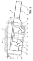
- FIG 3 there is shown a longitudinal sectional view along the plane III-III of the ventilating device 1 of figure 1 .
- the housing 3 comprises a casing 4 and an air outflow channel 3 provided with a discharge opening 18.
- the motor 6 extends, which motor supports the impeller wheel 13 via the shaft 14.
- the motor 6 is suspended from support arms 10, through openings of which threaded elements 16 extend, on which respective nuts 17 are screwed, on which the support arms 10 are supported.
- the support arms 10 of the ventilating device are suspended from the ceiling 15 via threaded connections 16, 17.
- the support arms 10 are suspended lower than on the part of the housing opposite the air outflow channel 3.
- the support arms rest on nuts 17 and support the motor 6 of the ventilating device.
- the motor 6 in turn supports the impeller wheel 13 via the shaft 14.
- the motor 6 and the impeller wheel 13 are thus completely supported by the support arms 10, as a result of which the housing 2 is neither loaded by the weight of the motor 6 and/or the impeller wheel 13 nor by vibrations generated within the housing 2 during rotation of the impeller wheel 13.
- the housing 2 itself is separately supported on the support arms 10, so that the housing 2 hardly needs to take up any supporting forces.
- the constructional requirements made of the housing are relatively modest, so that the housing 2 can be made of a relatively light material. This makes it possible to assemble the housing 2 of the ventilating device 1 from standard components, more in particular, part of a standard air duct can to this end be shortened and be provided with a transverse rear wall and with an outflow channel on the discharge side.
- the generation of an air flow by the impeller wheel will take place at an angle relative to the ceiling 15, and that in such a manner that the air flow is oriented at a downward angle from the impeller wheel 13.
- the nut 17 can be screwed up or down on the threaded element 16 on the side of the air outflow channel 3 so as to increase or reduce, respectively, the throw of the ventilating device.
- the inclination of the housing 2 relative to the ceiling 15 is slightly exaggerated here for the sake of clarity.
Landscapes
- Engineering & Computer Science (AREA)
- Mechanical Engineering (AREA)
- General Engineering & Computer Science (AREA)
- Structures Of Non-Positive Displacement Pumps (AREA)
Applications Claiming Priority (1)
| Application Number | Priority Date | Filing Date | Title |
|---|---|---|---|
| NL1034926A NL1034926C2 (nl) | 2008-01-18 | 2008-01-18 | Ventilatorinrichting met ophanging aan motor. |
Publications (2)
| Publication Number | Publication Date |
|---|---|
| EP2080912A2 true EP2080912A2 (de) | 2009-07-22 |
| EP2080912A3 EP2080912A3 (de) | 2011-12-07 |
Family
ID=39758713
Family Applications (1)
| Application Number | Title | Priority Date | Filing Date |
|---|---|---|---|
| EP09000419A Withdrawn EP2080912A3 (de) | 2008-01-18 | 2009-01-14 | Ventilationsgerät |
Country Status (2)
| Country | Link |
|---|---|
| EP (1) | EP2080912A3 (de) |
| NL (1) | NL1034926C2 (de) |
Cited By (1)
| Publication number | Priority date | Publication date | Assignee | Title |
|---|---|---|---|---|
| EP3367009A1 (de) * | 2017-02-28 | 2018-08-29 | Soler & Palau Research, S.L. | Ventilationsvorrichtung |
Citations (3)
| Publication number | Priority date | Publication date | Assignee | Title |
|---|---|---|---|---|
| FR1440375A (fr) | 1965-07-06 | 1966-05-27 | Sound Control Ltd | Ventilateur centrifuge insonorisé |
| EP1267132A1 (de) | 2001-06-13 | 2002-12-18 | Ce2S N.V. | Lüftungsvorrichtung und damit ausgerüstetes Lüftungssystem |
| EP1266132A1 (de) | 2000-03-13 | 2002-12-18 | Joseph M. Brady | Brennkraftmaschine mit einlasskammer und ihre benutzung |
Family Cites Families (5)
| Publication number | Priority date | Publication date | Assignee | Title |
|---|---|---|---|---|
| US2278581A (en) * | 1940-02-16 | 1942-04-07 | Dexter Macdougald | Attic ventilator |
| US2781963A (en) * | 1950-06-16 | 1957-02-19 | Guy S Faber | Blower |
| DE2215473C3 (de) * | 1972-03-29 | 1980-12-18 | Standard Elektrik Lorenz Ag, 7000 Stuttgart | Eigenschwingungsgedämpfter, geräuscharmer Radiallüfter |
| JPS5153606A (en) * | 1974-11-05 | 1976-05-12 | Sasakura Eng Co Ltd | Puroperafuanno soonboshofuanringu |
| DE9104643U1 (de) * | 1991-04-16 | 1991-10-10 | Keller Lufttechnik GmbH + Co KG, 7312 Kirchheim | Ventilatoreinheit |
-
2008
- 2008-01-18 NL NL1034926A patent/NL1034926C2/nl not_active IP Right Cessation
-
2009
- 2009-01-14 EP EP09000419A patent/EP2080912A3/de not_active Withdrawn
Patent Citations (3)
| Publication number | Priority date | Publication date | Assignee | Title |
|---|---|---|---|---|
| FR1440375A (fr) | 1965-07-06 | 1966-05-27 | Sound Control Ltd | Ventilateur centrifuge insonorisé |
| EP1266132A1 (de) | 2000-03-13 | 2002-12-18 | Joseph M. Brady | Brennkraftmaschine mit einlasskammer und ihre benutzung |
| EP1267132A1 (de) | 2001-06-13 | 2002-12-18 | Ce2S N.V. | Lüftungsvorrichtung und damit ausgerüstetes Lüftungssystem |
Cited By (1)
| Publication number | Priority date | Publication date | Assignee | Title |
|---|---|---|---|---|
| EP3367009A1 (de) * | 2017-02-28 | 2018-08-29 | Soler & Palau Research, S.L. | Ventilationsvorrichtung |
Also Published As
| Publication number | Publication date |
|---|---|
| NL1034926C2 (nl) | 2009-07-21 |
| EP2080912A3 (de) | 2011-12-07 |
Similar Documents
| Publication | Publication Date | Title |
|---|---|---|
| KR101558330B1 (ko) | 원심형 천장팬 | |
| US20090317240A1 (en) | Adjustable multi-outlet verticle tower fan | |
| US20080181783A1 (en) | Mounting system for supporting a ceiling fan assembly | |
| WO2018235947A1 (ja) | 空調室内機 | |
| KR20090015269A (ko) | 360도 선풍기 | |
| CN106152261A (zh) | 空调器室内机 | |
| EP2080912A2 (de) | Ventilationsgerät | |
| AU2015316169B2 (en) | Diffuser module | |
| CN209877129U (zh) | 柜式空调室内机 | |
| CN207350488U (zh) | 空调室内机 | |
| KR102629027B1 (ko) | 공기조화기 | |
| JP2011127497A (ja) | 天井扇 | |
| EP4660548A1 (de) | Montageelement zur befestigung eines mechanischen lüfters in einer dachentlüftungsvorrichtung und dachentlüftungsvorrichtung | |
| CN218544561U (zh) | 吊装式取暖设备及其吊顶式安装结构以及吸顶式安装结构 | |
| JP7807336B2 (ja) | 送風装置および空調装置 | |
| EP1483508B1 (de) | Elektrische absauganordnung | |
| US20230067624A1 (en) | Blower | |
| JP7612316B2 (ja) | 天井埋込型空気調和機 | |
| JP3145410U (ja) | 天井の軽量鋼構造体に取り付けるためのファン構造体 | |
| CN207378941U (zh) | 空调室内机 | |
| CN118613687A (zh) | 室内机以及空调机 | |
| WO2020130796A1 (en) | A ceiling-suspended air conditioning unit | |
| KR20250055099A (ko) | 기류 형성 어셈블리 및 이를 포함하는 공기청정기 | |
| KR200261810Y1 (ko) | 블로워의 수직 설치구조 | |
| CN115388457A (zh) | 吊装式取暖器及其吊顶式安装结构以及吸顶式安装结构 |
Legal Events
| Date | Code | Title | Description |
|---|---|---|---|
| PUAI | Public reference made under article 153(3) epc to a published international application that has entered the european phase |
Free format text: ORIGINAL CODE: 0009012 |
|
| AK | Designated contracting states |
Kind code of ref document: A2 Designated state(s): AT BE BG CH CY CZ DE DK EE ES FI FR GB GR HR HU IE IS IT LI LT LU LV MC MK MT NL NO PL PT RO SE SI SK TR |
|
| AX | Request for extension of the european patent |
Extension state: AL BA RS |
|
| PUAL | Search report despatched |
Free format text: ORIGINAL CODE: 0009013 |
|
| AK | Designated contracting states |
Kind code of ref document: A3 Designated state(s): AT BE BG CH CY CZ DE DK EE ES FI FR GB GR HR HU IE IS IT LI LT LU LV MC MK MT NL NO PL PT RO SE SI SK TR |
|
| AX | Request for extension of the european patent |
Extension state: AL BA RS |
|
| RIC1 | Information provided on ipc code assigned before grant |
Ipc: F04D 29/66 20060101ALI20111031BHEP Ipc: F04D 29/62 20060101ALI20111031BHEP Ipc: F04D 29/60 20060101AFI20111031BHEP |
|
| AKY | No designation fees paid | ||
| REG | Reference to a national code |
Ref country code: DE Ref legal event code: R108 Effective date: 20120816 |
|
| STAA | Information on the status of an ep patent application or granted ep patent |
Free format text: STATUS: THE APPLICATION IS DEEMED TO BE WITHDRAWN |
|
| 18D | Application deemed to be withdrawn |
Effective date: 20120609 |