EP2079227A1 - Cryptage à UV via un tramage intelligent - Google Patents
Cryptage à UV via un tramage intelligent Download PDFInfo
- Publication number
- EP2079227A1 EP2079227A1 EP09150382A EP09150382A EP2079227A1 EP 2079227 A1 EP2079227 A1 EP 2079227A1 EP 09150382 A EP09150382 A EP 09150382A EP 09150382 A EP09150382 A EP 09150382A EP 2079227 A1 EP2079227 A1 EP 2079227A1
- Authority
- EP
- European Patent Office
- Prior art keywords
- halftone
- phase
- document
- printed
- shifted
- Prior art date
- Legal status (The legal status is an assumption and is not a legal conclusion. Google has not performed a legal analysis and makes no representation as to the accuracy of the status listed.)
- Granted
Links
Images


Classifications
-
- H—ELECTRICITY
- H04—ELECTRIC COMMUNICATION TECHNIQUE
- H04N—PICTORIAL COMMUNICATION, e.g. TELEVISION
- H04N1/00—Scanning, transmission or reproduction of documents or the like, e.g. facsimile transmission; Details thereof
- H04N1/44—Secrecy systems
-
- H—ELECTRICITY
- H04—ELECTRIC COMMUNICATION TECHNIQUE
- H04N—PICTORIAL COMMUNICATION, e.g. TELEVISION
- H04N1/00—Scanning, transmission or reproduction of documents or the like, e.g. facsimile transmission; Details thereof
- H04N1/387—Composing, repositioning or otherwise geometrically modifying originals
-
- H—ELECTRICITY
- H04—ELECTRIC COMMUNICATION TECHNIQUE
- H04N—PICTORIAL COMMUNICATION, e.g. TELEVISION
- H04N1/00—Scanning, transmission or reproduction of documents or the like, e.g. facsimile transmission; Details thereof
- H04N1/40—Picture signal circuits
- H04N1/405—Halftoning, i.e. converting the picture signal of a continuous-tone original into a corresponding signal showing only two levels
- H04N1/4055—Halftoning, i.e. converting the picture signal of a continuous-tone original into a corresponding signal showing only two levels producing a clustered dots or a size modulated halftone pattern
-
- H—ELECTRICITY
- H04—ELECTRIC COMMUNICATION TECHNIQUE
- H04N—PICTORIAL COMMUNICATION, e.g. TELEVISION
- H04N1/00—Scanning, transmission or reproduction of documents or the like, e.g. facsimile transmission; Details thereof
- H04N1/46—Colour picture communication systems
- H04N1/52—Circuits or arrangements for halftone screening
Definitions
- Known digital image printing/copying systems produce documents of such high quality that a need has been identified to prevent effective printing/copying of certain documents such as high-value printed items including tickets, financial instruments, security passes, and the like.
- Known techniques include printing the original document in a manner such that it includes a digital "watermark" using only conventional paper and toner or ink.
- a digital watermark is defined as information, for example one or more letters, words, symbols or patterns, that is at least partially (preferably fully or at least substantially) hidden in a printed image under normal viewing conditions but that is more clearly discernable under certain specialized viewing conditions. Unauthorized reproduction of documents including such digital watermarks typical degrades or obscures the digital watermark, which can aid in detection of counterfeit documents.
- a fluorescence mark is one example of a known digital watermark.
- Methods and systems are known for including fluorescence marks in printed documents using conventional papers (e.g., ordinary "copy paper” or “printer paper") and ordinary inks/toners (e.g., CMYK ink/toner), specifically by using metameric colorant mixtures.
- conventional papers e.g., ordinary "copy paper” or “printer paper”
- ordinary inks/toners e.g., CMYK ink/toner
- metameric colorant mixtures e.g., CMYK ink/toner
- visible lighting conditions e.g., electromagnetic radiation wavelengths of about 400 - 700 nanometers (nm)
- the different colorant mixtures that are printed on respective adjacent portions of the paper together define an overall printed document region that appears substantially uniform in color.
- UV lighting e.g., electromagnetic radiation wavelengths shorter than about 400nm
- these different colorant mixtures exhibit different UV absorption and, thus, different suppression of UV fluorescence of the optical brightening agents used in conventional printing/copying papers such that the region printed with the colorant mixture that suppresses less of the substrate fluorescence appears as a lighter/brighter region while the adjacent area printed with the colorant mixture that strongly suppresses substrate fluorescence appears as a darker region.
- These contrast variations under UV lighting are used to create watermark patterns, e.g., numbers, letters, symbols, shapes.
- FIG. 1 An example of this is shown in FIG. 1 , wherein a colorant mixture "B" is selected and applied to patch area BP which, in this example, is shaped as the alphanumeric symbol "0". Further, a colorant mixture "A” is selected and applied to patch area AP arranged here in substantially close spatial proximity to patch area BP, and thereby providing a background around patch area BP. Both colorant mixture A and colorant mixture B are comprised of a suitably selected colorant or colorant mixtures, but colorant mixtures A and B are different mixtures. Each colorant mixture A or B may be, for example, either a single CMYK colorant or any mixture of CMYK colorants.
- colorant mixture A will be selected so as to provide higher UV absorption (greater substrate fluorescence suppression) than that selected for colorant mixture B.
- the colorant mixtures A and B will also be selected to match each other closely in their average color and luminance when viewed under visible light conditions.
- patch BP will appear brighter as compared to patch AP, due to the relatively limited suppression of the fluorescence of the optical brightening agents in the paper substrate as compared to the patch AP, thus forming a watermark W1.
- patches AP,BP are at least substantially indistinguishable.
- an approximate 50% gray color may be realized with a halftone of black (K) colorant only and used for colorant mixture B to print patch BP. This may then be color-matched against a colorant mixture comprising yellow (Y), cyan (C), and magenta (M) that yield a similar approximate 50% gray color, A which is used to print the patch AP.
- colorant mixture A will cover more of the paper, thus providing much higher suppression of native substrate fluorescence as compared to the patch BP, so that under UV lighting conditions, the patch BP will be readily apparent as a watermark W1.
- the two colorant mixtures will appear quite nearly identical "gray" under normal visible light viewing as shown at VIS in FIG. 1 . Thus, when a document including such a fluorescence mark is subjected to UV illumination, the watermark W1 is revealed. A printed "look-alike" document or mere photocopy will not properly reproduce the watermark.
- a correlation mark is another known watermarking technique.
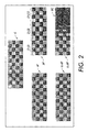
- a checkerboard halftone pattern HP is printed on paper by a regular 45-degree cluster halftone screen and has 13 columns of halftone cells.
- Another checkerboard halftone pattern HP' covering an equal spatial area overall is printed on paper by a halftone screen having four slightly stretched columns C5-C8 in the middle section, such that the halftone pattern HP' has only 12 columns over the same spatial width as the pattern HP.
- the patterns HP and HP' are perceived as the same gray level to a human observer and the phase shift is substantially hidden under normal image viewing conditions.
- the phase which represents the transition between white and black, has changed from "in phase” with the pattern HP, (0 radian phase shift), for columns C1-C4, to "opposite phase” ( ⁇ radian phase shift) for columns C9-C12, with varying, increasing phase shift for the stretched columns C5-C8.
- a transparency key K is printed with the halftone pattern HP and overlaid with the paper-printed halftone pattern HP as shown at K+HP, the result is unchanged relative to the original printed pattern HP because the key K and printed pattern can be registered, solid-on-solid, blank-on-blank.
- the original printed checkerboard pattern HP' gradually disappears in proportion to the phase difference between the pattern HP' and the key K moving from left to right in the image, until the checkerboard pattern HP' is completely black (or other solid color) where the pattern HP' and key K are opposite phase.
- the average reflectance is higher in the registered regions C1-C4 and lower in the partially phase-shifted regions C5-C8 and still lower in the opposite phase regions C9-C12.
- a high contrast watermark W2 can be defined by the low reflectance areas where the key and halftone pattern are out of phase (conversely, a watermark can be defined by the high reflectance areas where the key and printed document are in phase). Accordingly, a document can be printed in this manner to include a watermark that is completely or at least substantially undetectable until a corresponding transparency key is overlaid to reveal the phase-shifted halftone regions.
- fluorescence marks and correlation marks are highly effective, a need has been identified for a watermark that is less apparent under ambient lighting conditions and more apparent during a security check of the document, without requiring use of a separate transparency overlay key. Accordingly, the present development combines principles of fluorescence marks and correlation marks to achieve these goals as disclosed below.
- a method for encryption of a digital watermark by intelligent halftoning includes receiving image data that define at least a portion of a document to be printed in terms of at least three halftone images corresponding respectively to three printing colorants, each of the three halftone images comprising a plurality of halftone cells.
- the image data are modified by phase-shifting some of the halftone cells of at least one of the halftone images relative to the other halftone images to encode a watermark within the portion of the document such that the at least one halftone image includes a phase-shifted region and a non-phase-shifted region.
- the modified image data are used to print the portion of the document on a substrate that will fluoresce when subjected to UV illumination.
- the printed portion of the document includes a first printed pattern resulting from the phase-shifted region and a second printed pattern resulting from the non-phase-shifted region.
- the first and second patterns of the printed portion of the document appear substantially similar when the portion of the document is viewed in visible light, and appear dissimilar when the portion of the document is viewed in UV light such that the watermark encoded in the modified image data is perceptible when the portion of the document is viewed in UV light and is hidden when the portion of the document is viewed in visible light.
- a system for printing a document with a watermark includes means for receiving image data that define at least a portion of a document to be printed in terms of at least three halftone images corresponding respectively to three printing colorants, each of the three halftone images comprising a plurality of halftone cells.
- the system also includes means for modifying the image data by phase-shifting some of the halftone cells of at least one of the halftone images relative to the other halftone images to encode a watermark within the portion of the document, such that the at least one phase-shifted halftone image includes a phase-shifted region and a non-phase-shifted region.
- the system further includes means for printing the portion of the document on a substrate that will fluoresce when subjected to UV illumination according to the modified image data, wherein printed portion of the document includes a first printed pattern resulting from the phase-shifted region and a second printed pattern resulting from the non-phase-shifted region, and wherein the first and second patterns of the printed portion of the document appear substantially similar when the portion of the document is viewed in visible light, and appear dissimilar when the portion of the document is viewed in UV light such that the watermark encoded in the modified image data is perceptible when the portion of the document is viewed in UV light and is hidden when the document is viewed in visible light.
- a printed color document includes three or more colorants printed on a substrate that will fluoresce when subjected to UV illumination.
- One of the colorants is rendered with a phase-shifted halftone in selected regions that encode a watermark and the other colorants are rendered with halftones that serve as a distracting pattern obscuring the visibility of the phase shifted regions with respect to the non-phase-shifted regions under visible light conditions, but allowing the phase shifted regions to be visibly distinguished from the non-phase-shifted regions when the printed document is subjected to UV light.
- FIG. 3 illustrates one example of an apparatus for implementing a method in accordance with the present development.
- the apparatus 10 comprises an image processing unit (IPU) 14 for carrying out the digital image processing operations disclosed herein.
- the IPU 14 is defined by electronic circuitry and/or software that is dedicated to digital image processing and/or can comprise a general purpose computer programmed to implement the image processing operations disclosed herein.
- the IPU 14 is adapted to receive image data from a source such as a scanner 16a, computer 16b (e.g., a digital front-end (DFE)), and/or data storage 16c or another source that is part of the apparatus 10 and/or that is operably connected to the IPU 14 through a network or other means.
- the apparatus 10 comprises an image output or printing unit 20 including a xerographic, ink-jet, or other print engine 22 for printing the image data on paper, a transparency, or another recording medium using toner and/or ink as is known in the art, using the CMYK or other multi-colorant color space 24.
- the printer unit 20 further comprises a printed output station 26 for physical output of the final printed product such as printed paper, transparencies or other recording media sheets. Examples of suitable commercially available systems 10 include, but are not limited to, the Phaser TM , WorkCentre TM , DocuColor TM , and iGen3 TM printing / copying / digital press systems available from X
- FIG. 4 discloses UV encryption via intelligent halftoning in accordance with the present development, using the system of FIG. 3 or the like.
- an electronic digital image document D to be printed at the image printing unit 20 comprises multiple monochromatic binary images or separations such as the illustrated cyan C, magenta M, yellow Y, and black K separations (the black separation K is optional for implementing the present development and thus is shown in broken lines and not further discussed).
- a watermark W to be encoded in the digital image document I is selected and input to the IPU 14.
- the selected watermark must be or be converted to a low-frequency watermark, e.g., a slowly varying pattern or symbol encompassing multiple halftone cells, because the present development relies only on phase shifts in one of the halftone separations to encode the watermark, and such a method cannot be used to encode fine lines or like high-frequency data.
- the yellow separation Y is chosen for phase-shifting.
- the binary image defining the yellow separation Y of the electronic image document I is thus input to the IPU 14.
- the watermark W is selected and input to the IPU 14 as a text string of one or more characters, and the IPU converts the text string to a low-frequency binary image suitable for being encoded in the digital image document I.
- the halftone cells of the yellow separation Y are modified such the halftone cells located to coincide spatially with the selected low-frequency watermark W are shifted in phase by a certain amount, while the remainder of the halftone cells of the yellow separation are shifted in phase by a different amount.
- the halftone cells of the yellow separation Y that are located to coincide spatially with the selected low-frequency watermark W are defined in the modified yellow separation Y' using non phase-shifted (i.e., 0 radian phase-shifted) halftone cells, while the remainder of the halftone cells of the yellow separation Y are defined in the modified yellow separation Y' to be opposite phase, i.e., ⁇ radian phase-shifted.
- the non-yellow C,M, and optional K separations of the color image document I are not altered as part of the watermark encoding process.
- the selected watermark is encoded in a constant color region (i.e., fixed contone digital input region) of the digital image document I, which could be the entire spatial extent of the digital image document or only a band or other portion thereof.
- a 50% digital input level for the cyan C, magenta M, and yellow Y separations is used, but other digital input levels are contemplated and fall within the scope of the present development, provided they result in output of a printed constant color region.
- the watermarked image I' comprises the separations CMY' and is then printed as a document D as shown at S4 in a conventional manner using the image printing unit 20, i.e., using the separation data CMY' and corresponding CMY inks/toners on conventional printing/copying paper or another substrate that includes optical brightening agents that fluoresce under UV illumination, where only the yellow separation Y' includes the phase-shift encoded watermark and is printed with such phase shifts.
- the printing operation S4 is implemented using known halftoning techniques.
- halftone screen rotation angles that will produce halftone rosettes as are generally known in the art.
- the cyan C, magenta M, and yellow Y screen angles are 15, 75, and 45 degrees, respectively, with all screen frequencies being set equal, e.g., at 35.4 lines per inch.
- the magenta screen angle is 60 degrees from the cyan screen angle
- the yellow screen angle is 30 degrees from the cyan screen angle.
- FIG. 5A diagrammatically illustrates a constant color watermark region G of the printed digital image document D that comprises a watermark encoded via intelligent halftoning (i.e., phase shifts in only the yellow separation) as described above.
- the region G is defined by a group of halftone rosettes RT comprising cyan, magenta, and yellow halftone dots CD,MD,YD printed according to the separation data C,M,Y' (for ease of illustration, the rosettes RT are shown arranged in a uniform pattern, but those of ordinary skill in the art will recognize that rosettes RT can also be arranged in a non-uniform pattern that is not periodic or described by a fixed spatial frequency.
- the spatial location of the corresponding yellow halftone dots YD of the watermarked image region G vary relative to the cyan and magenta dots CD,MD depending upon which rosettes RT are considered.
- the ⁇ radian phase-shifted regions of the yellow separation Y' result in the corresponding yellow halftone dots YD being offset relative to the cyan and magenta dots CD,MD in the rosette resulting in a dot-centered rosette DC, with a yellow halftone dot YD being located fully or substantially in the center of the rosette DC, surrounded by cyan and magenta halftone dots CD,MD and other phase-shifted yellow halftone dots YD.
- the 0 radian phase-shifted regions of the yellow separation Y' result in the corresponding yellow halftone dots being in phase with the cyan and magenta halftone dots CD,MD so that the corresponding rosettes are clear-centered rosettes CC in which the cyan, magenta, and yellow halftone dots CD,MD,YD are all located in phase with each other so as to leave the rosette center open.
- the total ink/toner coverage on the paper substrate for phase-shifted (dot-centered) rosette DC is greater than a corresponding non phase-shifted (clear-centered) rosette CC, given that the yellow dots YD of the phase-shifted rosettes are located in areas of the paper or other substrate that would otherwise be at least partially uncovered with ink/toner.
- the region G of the document D is shown as it will appear under visible light VIS to a human observer.
- the cyan and magenta halftone dots CD,MD result in a high-frequency 2 colorant moiré pattern M that at least substantially or completely obscures the watermark W encoded by the yellow halftone dots YD, due to the relatively low contrast and visibility of the yellow halftone dots YD as compared to the moiré pattern M.
- the same region G is shown in FIG. 5C as it will appear to a human observer under UV illumination, where the yellow halftone dots YD suppress substrate fluorescence and appear dark or black, together with the cyan and magenta halftone dots CD,MD that also appear dark or black.
- phase-shifted (dot-centered) rosettes DC appear more dense and darker as compared to the non phase-shifted (clear-centered).
- the phase-shifted halftone cells of the yellow separation Y' correspond to the darker areas of the printed constant color region G, while the non phase-shifted halftone cells of the yellow separation Y' correspond to the lighter/brighter areas of the printed constant color region G so as to reveal the watermark W (a capital "T" in the illustrated example) due to substrate fluorescence.
- the yellow halftone dots YD that are out-of-phase relative to the cyan and magenta halftone dots CD,MD provide additive substrate coverage and, thus, greater UV fluorescence suppression as compared to yellow halftone dots YD that are in-phase relative to the cyan and magenta halftone dots CD,MD.
- the substrate coverage of the in-phase yellow halftone dots YD is partially redundant to the already present cyan and magenta halftone dots CD,MD.
- a document D' is printed using the original C,M,Y separation data I of FIG. 4 , while the document D is printed with a digital watermark W encoded by intelligent halftoning in accordance with the present development using the separation data CMY'. It can be seen that the documents D and D' will appear in visible light VIS to be at least substantially identical. When subjected to UV illumination, however, the documents D and D' appear very different, with the watermark W of the document D being revealed.
- FIGS. 5A-5C should not be used to limit the present development to use of a uniform rosette moiré pattern M to conceal the phase-shift encoded watermark W.
- An alternative distracting pattern can be provided by a non-uniform rosette pattern or a stochastic pattern.
- FIG. 7 illustrates a two colorant non-uniform rosette pattern M' defined by e.g., cyan and magenta ink/toner halftone dots CD,MD.
- FIGS. 8A and 8B illustrate single colorant (e.g., yellow) halftone images Y1,Y2 defined by yellow ink/toner halftone dots YD. The halftone images of FIGS.
- FIGS. 9A and 9B respectively illustrate printed documents A and B wherein the distracting rosette pattern M' of FIG. 7 combined with the halftone images Y1,Y2 of FIGS. 8A and 8B , respectively, as viewed in visible light. In visible light, it is difficult to discern any difference in the overall appearance of the printed documents A and B of FIGS.
Applications Claiming Priority (1)
| Application Number | Priority Date | Filing Date | Title |
|---|---|---|---|
| US12/013,664 US7903291B2 (en) | 2008-01-14 | 2008-01-14 | UV encryption via intelligent halftoning |
Publications (2)
| Publication Number | Publication Date |
|---|---|
| EP2079227A1 true EP2079227A1 (fr) | 2009-07-15 |
| EP2079227B1 EP2079227B1 (fr) | 2017-01-04 |
Family
ID=40427776
Family Applications (1)
| Application Number | Title | Priority Date | Filing Date |
|---|---|---|---|
| EP09150382.1A Expired - Fee Related EP2079227B1 (fr) | 2008-01-14 | 2009-01-12 | Cryptage à UV via un tramage intelligent |
Country Status (3)
| Country | Link |
|---|---|
| US (1) | US7903291B2 (fr) |
| EP (1) | EP2079227B1 (fr) |
| JP (1) | JP5372530B2 (fr) |
Cited By (5)
| Publication number | Priority date | Publication date | Assignee | Title |
|---|---|---|---|---|
| WO2011109349A2 (fr) | 2010-03-05 | 2011-09-09 | Adams Wesley T | Impression lumineuse |
| JP2013037066A (ja) * | 2011-08-04 | 2013-02-21 | Ricoh Co Ltd | 画像形成装置、及び画像形成プログラム |
| CN108063881A (zh) * | 2017-12-27 | 2018-05-22 | 四川大学 | 彩色图像的双柱面随机相位编码加密方法 |
| CN111612682A (zh) * | 2019-02-26 | 2020-09-01 | 浙江大学 | 一种水印处理方法及其装置 |
| EP3877193B1 (fr) | 2018-11-09 | 2022-12-28 | Hueck Folien Gesellschaft m.b.H. | Procédé pour la fabrication d'une caractéristique de sécurité |
Families Citing this family (12)
| Publication number | Priority date | Publication date | Assignee | Title |
|---|---|---|---|---|
| US8509474B1 (en) * | 2009-12-11 | 2013-08-13 | Digimarc Corporation | Digital watermarking methods, apparatus and systems |
| US8179570B2 (en) * | 2009-03-31 | 2012-05-15 | Xerox Corporation | Generating image embedded with UV fluorescent watermark by combining binary images generated using different halftone strategies |
| JP4875723B2 (ja) * | 2009-04-24 | 2012-02-15 | シャープ株式会社 | 画像形成装置 |
| JP2011109639A (ja) * | 2009-10-20 | 2011-06-02 | Canon Inc | 画像処理装置及びその制御方法 |
| US8451501B2 (en) * | 2010-12-13 | 2013-05-28 | Xerox Corporation | Watermark decoding via spectral analysis of pixel spacing |
| CN108141506B (zh) * | 2015-09-29 | 2020-01-03 | 惠普深蓝有限责任公司 | 将图像转换为多个半色调图像的系统、方法及计算机介质 |
| EP3552380B1 (fr) * | 2017-04-18 | 2022-11-30 | Hewlett-Packard Development Company, L.P. | Support de données |
| CN107730432B (zh) * | 2017-08-31 | 2020-01-24 | 深圳壹账通智能科技有限公司 | 图片处理方法及应用服务器 |
| US10284740B1 (en) * | 2017-12-22 | 2019-05-07 | Xerox Corporation | Copy identification with ultraviolet light exposure |
| US10855878B2 (en) * | 2018-03-23 | 2020-12-01 | Xerox Corporation | Segmentation hiding layer for vector pattern correlation marks |
| US10582078B1 (en) | 2019-05-03 | 2020-03-03 | Xerox Corporation | Distinguishing original from copy using ultraviolet light to reveal hidden security printing features |
| US10999466B1 (en) * | 2020-07-14 | 2021-05-04 | Xerox Corporation | Identifying original and copy using ultraviolet light to reveal hidden security printing features |
Citations (4)
| Publication number | Priority date | Publication date | Assignee | Title |
|---|---|---|---|---|
| EP0953939A2 (fr) * | 1998-04-29 | 1999-11-03 | Xerox Corporation | Filigranes numériques utilisant ecrans stoclustiques avec décalage de phases |
| WO2003005291A1 (fr) * | 2001-07-02 | 2003-01-16 | Digimarc Corporation | Occultation d'informations dephasees dans des canaux couleurs |
| US20070262579A1 (en) * | 2006-05-11 | 2007-11-15 | Xerox Corporation | Substrate fluorescence pattern mask for embedding information in printed documents |
| US20070264476A1 (en) * | 2006-05-11 | 2007-11-15 | Xerox Corporation | Substrate fluorescence mask for embedding information in printed documents |
Family Cites Families (9)
| Publication number | Priority date | Publication date | Assignee | Title |
|---|---|---|---|---|
| DE69425244T2 (de) * | 1994-04-27 | 2001-01-25 | Agfa Gevaert Nv | Tonabhängige Rosettenstrukturen bei der Mehrschichthalbtonrasterung durch Phasenmodulation |
| US7286682B1 (en) * | 2000-08-31 | 2007-10-23 | Xerox Corporation | Show-through watermarking of duplex printed documents |
| US7580153B2 (en) * | 2005-12-21 | 2009-08-25 | Xerox Corporation | Printed visible fonts with attendant background |
| US8980504B2 (en) * | 2006-05-11 | 2015-03-17 | Xerox Corporation | Substrate fluorescence mask utilizing a multiple color overlay for embedding information in printed documents |
| US7800785B2 (en) * | 2007-05-29 | 2010-09-21 | Xerox Corporation | Methodology for substrate fluorescent non-overlapping dot design patterns for embedding information in printed documents |
| US8821996B2 (en) * | 2007-05-29 | 2014-09-02 | Xerox Corporation | Substrate fluorescent non-overlapping dot patterns for embedding information in printed documents |
| US8077907B2 (en) * | 2007-08-31 | 2011-12-13 | Xerox Corporation | System and method for the generation of correlation-based digital watermarks |
| US7894626B2 (en) * | 2007-08-31 | 2011-02-22 | Xerox Corporation | System and method for the generation of multiple angle correlation-based digital watermarks |
| US8009329B2 (en) * | 2007-11-09 | 2011-08-30 | Xerox Corporation | Fluorescence-based correlation mark for enhanced security in printed documents |
-
2008
- 2008-01-14 US US12/013,664 patent/US7903291B2/en not_active Expired - Fee Related
-
2009
- 2009-01-12 EP EP09150382.1A patent/EP2079227B1/fr not_active Expired - Fee Related
- 2009-01-13 JP JP2009005005A patent/JP5372530B2/ja not_active Expired - Fee Related
Patent Citations (4)
| Publication number | Priority date | Publication date | Assignee | Title |
|---|---|---|---|---|
| EP0953939A2 (fr) * | 1998-04-29 | 1999-11-03 | Xerox Corporation | Filigranes numériques utilisant ecrans stoclustiques avec décalage de phases |
| WO2003005291A1 (fr) * | 2001-07-02 | 2003-01-16 | Digimarc Corporation | Occultation d'informations dephasees dans des canaux couleurs |
| US20070262579A1 (en) * | 2006-05-11 | 2007-11-15 | Xerox Corporation | Substrate fluorescence pattern mask for embedding information in printed documents |
| US20070264476A1 (en) * | 2006-05-11 | 2007-11-15 | Xerox Corporation | Substrate fluorescence mask for embedding information in printed documents |
Non-Patent Citations (1)
| Title |
|---|
| WANG, SHEN-GE: "Uniform rosette for moiré-free color halftoning", COLOR IMAGING XII: PROCESSING, HADRCOPY AND APPLICATIONS, vol. 6493, 2007, pages 1 - 11, XP002519462 * |
Cited By (8)
| Publication number | Priority date | Publication date | Assignee | Title |
|---|---|---|---|---|
| WO2011109349A2 (fr) | 2010-03-05 | 2011-09-09 | Adams Wesley T | Impression lumineuse |
| EP2542418A2 (fr) * | 2010-03-05 | 2013-01-09 | Wesley T. Adams | Impression lumineuse |
| EP2542418A4 (fr) * | 2010-03-05 | 2013-11-27 | Wesley T Adams | Impression lumineuse |
| JP2013037066A (ja) * | 2011-08-04 | 2013-02-21 | Ricoh Co Ltd | 画像形成装置、及び画像形成プログラム |
| CN108063881A (zh) * | 2017-12-27 | 2018-05-22 | 四川大学 | 彩色图像的双柱面随机相位编码加密方法 |
| EP3877193B1 (fr) | 2018-11-09 | 2022-12-28 | Hueck Folien Gesellschaft m.b.H. | Procédé pour la fabrication d'une caractéristique de sécurité |
| CN111612682A (zh) * | 2019-02-26 | 2020-09-01 | 浙江大学 | 一种水印处理方法及其装置 |
| CN111612682B (zh) * | 2019-02-26 | 2023-05-19 | 浙江大学 | 一种水印处理方法及其装置 |
Also Published As
| Publication number | Publication date |
|---|---|
| JP5372530B2 (ja) | 2013-12-18 |
| JP2009171582A (ja) | 2009-07-30 |
| US7903291B2 (en) | 2011-03-08 |
| EP2079227B1 (fr) | 2017-01-04 |
| US20090180152A1 (en) | 2009-07-16 |
Similar Documents
| Publication | Publication Date | Title |
|---|---|---|
| EP2079227B1 (fr) | Cryptage à UV via un tramage intelligent | |
| US8009329B2 (en) | Fluorescence-based correlation mark for enhanced security in printed documents | |
| JP5285642B2 (ja) | 高解像度のスケール変更可能なグロス効果 | |
| US7639400B2 (en) | Glossmark image simulation with application of background modified gloss effect image | |
| JP4339510B2 (ja) | デジタルスクリーニングを用いた偽造防止方法および装置 | |
| US8444181B2 (en) | Single-color screen patterns for copy protection | |
| US8545928B2 (en) | Double layer UV variable data text | |
| US20070257977A1 (en) | Security enhanced print media with copy protection | |
| US8164799B2 (en) | Digitally printed color anti-copy document in any resolution and processes and products therefor | |
| Amidror | New print-based security strategy for the protection of valuable documents and products using moiré intensity profiles | |
| US20070086070A1 (en) | Full Color Scanning Protection of a Document | |
| US7512248B2 (en) | Method of incorporating a secondary image into a primary image | |
| JP5138020B2 (ja) | 画像処理装置、画像形成装置、画像処理方法、コンピュータプログラム及び記録媒体 | |
| JP2008503155A (ja) | ドキュメントの全カラー走査保護 | |
| JP5669538B2 (ja) | 画像処理装置、画像形成装置、画像処理方法、コンピュータプログラム及び記録媒体 | |
| US20070133023A1 (en) | Document For Determining Interference Scanning Frequencies | |
| JP3765421B2 (ja) | 画像変換装置および方法、パターン読取装置および方法並びにプログラム | |
| JP2014027489A (ja) | 画像処理装置及び画像形成装置 |
Legal Events
| Date | Code | Title | Description |
|---|---|---|---|
| PUAI | Public reference made under article 153(3) epc to a published international application that has entered the european phase |
Free format text: ORIGINAL CODE: 0009012 |
|
| AK | Designated contracting states |
Kind code of ref document: A1 Designated state(s): AT BE BG CH CY CZ DE DK EE ES FI FR GB GR HR HU IE IS IT LI LT LU LV MC MK MT NL NO PL PT RO SE SI SK TR |
|
| AX | Request for extension of the european patent |
Extension state: AL BA RS |
|
| 17P | Request for examination filed |
Effective date: 20100115 |
|
| 17Q | First examination report despatched |
Effective date: 20100209 |
|
| AKX | Designation fees paid |
Designated state(s): DE FR GB |
|
| GRAP | Despatch of communication of intention to grant a patent |
Free format text: ORIGINAL CODE: EPIDOSNIGR1 |
|
| INTG | Intention to grant announced |
Effective date: 20160908 |
|
| GRAS | Grant fee paid |
Free format text: ORIGINAL CODE: EPIDOSNIGR3 |
|
| GRAA | (expected) grant |
Free format text: ORIGINAL CODE: 0009210 |
|
| AK | Designated contracting states |
Kind code of ref document: B1 Designated state(s): DE FR GB |
|
| REG | Reference to a national code |
Ref country code: GB Ref legal event code: FG4D |
|
| REG | Reference to a national code |
Ref country code: FR Ref legal event code: PLFP Year of fee payment: 9 |
|
| REG | Reference to a national code |
Ref country code: DE Ref legal event code: R096 Ref document number: 602009043469 Country of ref document: DE |
|
| REG | Reference to a national code |
Ref country code: DE Ref legal event code: R097 Ref document number: 602009043469 Country of ref document: DE |
|
| PLBE | No opposition filed within time limit |
Free format text: ORIGINAL CODE: 0009261 |
|
| STAA | Information on the status of an ep patent application or granted ep patent |
Free format text: STATUS: NO OPPOSITION FILED WITHIN TIME LIMIT |
|
| 26N | No opposition filed |
Effective date: 20171005 |
|
| REG | Reference to a national code |
Ref country code: FR Ref legal event code: PLFP Year of fee payment: 10 |
|
| PGFP | Annual fee paid to national office [announced via postgrant information from national office to epo] |
Ref country code: FR Payment date: 20191219 Year of fee payment: 12 |
|
| PGFP | Annual fee paid to national office [announced via postgrant information from national office to epo] |
Ref country code: GB Payment date: 20191223 Year of fee payment: 12 |
|
| PGFP | Annual fee paid to national office [announced via postgrant information from national office to epo] |
Ref country code: DE Payment date: 20201217 Year of fee payment: 13 |
|
| GBPC | Gb: european patent ceased through non-payment of renewal fee |
Effective date: 20210112 |
|
| PG25 | Lapsed in a contracting state [announced via postgrant information from national office to epo] |
Ref country code: FR Free format text: LAPSE BECAUSE OF NON-PAYMENT OF DUE FEES Effective date: 20210131 |
|
| PG25 | Lapsed in a contracting state [announced via postgrant information from national office to epo] |
Ref country code: GB Free format text: LAPSE BECAUSE OF NON-PAYMENT OF DUE FEES Effective date: 20210112 |
|
| REG | Reference to a national code |
Ref country code: DE Ref legal event code: R119 Ref document number: 602009043469 Country of ref document: DE |
|
| PG25 | Lapsed in a contracting state [announced via postgrant information from national office to epo] |
Ref country code: DE Free format text: LAPSE BECAUSE OF NON-PAYMENT OF DUE FEES Effective date: 20220802 |