EP2079125A2 - Verfahren zur Steuerung des Aufladevorgangs einer Batterie - Google Patents
Verfahren zur Steuerung des Aufladevorgangs einer Batterie Download PDFInfo
- Publication number
- EP2079125A2 EP2079125A2 EP08291208A EP08291208A EP2079125A2 EP 2079125 A2 EP2079125 A2 EP 2079125A2 EP 08291208 A EP08291208 A EP 08291208A EP 08291208 A EP08291208 A EP 08291208A EP 2079125 A2 EP2079125 A2 EP 2079125A2
- Authority
- EP
- European Patent Office
- Prior art keywords
- battery
- temperature
- current
- charge
- accumulators
- Prior art date
- Legal status (The legal status is an assumption and is not a legal conclusion. Google has not performed a legal analysis and makes no representation as to the accuracy of the status listed.)
- Granted
Links
- 238000000034 method Methods 0.000 title claims abstract description 16
- 229910005580 NiCd Inorganic materials 0.000 claims 1
- 229910005813 NiMH Inorganic materials 0.000 claims 1
- OJIJEKBXJYRIBZ-UHFFFAOYSA-N cadmium nickel Chemical compound [Ni].[Cd] OJIJEKBXJYRIBZ-UHFFFAOYSA-N 0.000 abstract description 3
- 229910052987 metal hydride Inorganic materials 0.000 abstract description 3
- 238000004088 simulation Methods 0.000 description 11
- 238000010438 heat treatment Methods 0.000 description 8
- 238000012423 maintenance Methods 0.000 description 4
- 239000003792 electrolyte Substances 0.000 description 3
- 238000007726 management method Methods 0.000 description 3
- 230000015556 catabolic process Effects 0.000 description 2
- 238000006731 degradation reaction Methods 0.000 description 2
- 238000007599 discharging Methods 0.000 description 2
- 230000000694 effects Effects 0.000 description 2
- 239000000126 substance Substances 0.000 description 2
- 206010063493 Premature ageing Diseases 0.000 description 1
- 208000032038 Premature aging Diseases 0.000 description 1
- XUIMIQQOPSSXEZ-UHFFFAOYSA-N Silicon Chemical compound [Si] XUIMIQQOPSSXEZ-UHFFFAOYSA-N 0.000 description 1
- 150000001875 compounds Chemical class 0.000 description 1
- 239000002826 coolant Substances 0.000 description 1
- 230000006866 deterioration Effects 0.000 description 1
- 230000005611 electricity Effects 0.000 description 1
- 238000003487 electrochemical reaction Methods 0.000 description 1
- 238000004880 explosion Methods 0.000 description 1
- 239000007788 liquid Substances 0.000 description 1
- 238000012986 modification Methods 0.000 description 1
- 230000004048 modification Effects 0.000 description 1
- 238000012545 processing Methods 0.000 description 1
- 238000005215 recombination Methods 0.000 description 1
- 230000006798 recombination Effects 0.000 description 1
- 229910052710 silicon Inorganic materials 0.000 description 1
- 239000010703 silicon Substances 0.000 description 1
- 230000002123 temporal effect Effects 0.000 description 1
- 238000012546 transfer Methods 0.000 description 1
- 238000009423 ventilation Methods 0.000 description 1
- 238000010792 warming Methods 0.000 description 1
Images
Classifications
-
- H—ELECTRICITY
- H01—ELECTRIC ELEMENTS
- H01M—PROCESSES OR MEANS, e.g. BATTERIES, FOR THE DIRECT CONVERSION OF CHEMICAL ENERGY INTO ELECTRICAL ENERGY
- H01M10/00—Secondary cells; Manufacture thereof
- H01M10/42—Methods or arrangements for servicing or maintenance of secondary cells or secondary half-cells
- H01M10/44—Methods for charging or discharging
- H01M10/441—Methods for charging or discharging for several batteries or cells simultaneously or sequentially
-
- H—ELECTRICITY
- H01—ELECTRIC ELEMENTS
- H01M—PROCESSES OR MEANS, e.g. BATTERIES, FOR THE DIRECT CONVERSION OF CHEMICAL ENERGY INTO ELECTRICAL ENERGY
- H01M10/00—Secondary cells; Manufacture thereof
- H01M10/34—Gastight accumulators
-
- H—ELECTRICITY
- H01—ELECTRIC ELEMENTS
- H01M—PROCESSES OR MEANS, e.g. BATTERIES, FOR THE DIRECT CONVERSION OF CHEMICAL ENERGY INTO ELECTRICAL ENERGY
- H01M10/00—Secondary cells; Manufacture thereof
- H01M10/34—Gastight accumulators
- H01M10/345—Gastight metal hydride accumulators
-
- H—ELECTRICITY
- H01—ELECTRIC ELEMENTS
- H01M—PROCESSES OR MEANS, e.g. BATTERIES, FOR THE DIRECT CONVERSION OF CHEMICAL ENERGY INTO ELECTRICAL ENERGY
- H01M10/00—Secondary cells; Manufacture thereof
- H01M10/42—Methods or arrangements for servicing or maintenance of secondary cells or secondary half-cells
- H01M10/425—Structural combination with electronic components, e.g. electronic circuits integrated to the outside of the casing
-
- H—ELECTRICITY
- H01—ELECTRIC ELEMENTS
- H01M—PROCESSES OR MEANS, e.g. BATTERIES, FOR THE DIRECT CONVERSION OF CHEMICAL ENERGY INTO ELECTRICAL ENERGY
- H01M10/00—Secondary cells; Manufacture thereof
- H01M10/42—Methods or arrangements for servicing or maintenance of secondary cells or secondary half-cells
- H01M10/46—Accumulators structurally combined with charging apparatus
-
- H—ELECTRICITY
- H02—GENERATION; CONVERSION OR DISTRIBUTION OF ELECTRIC POWER
- H02J—CIRCUIT ARRANGEMENTS OR SYSTEMS FOR SUPPLYING OR DISTRIBUTING ELECTRIC POWER; SYSTEMS FOR STORING ELECTRIC ENERGY
- H02J7/00—Circuit arrangements for charging or depolarising batteries or for supplying loads from batteries
- H02J7/007—Regulation of charging or discharging current or voltage
- H02J7/007188—Regulation of charging or discharging current or voltage the charge cycle being controlled or terminated in response to non-electric parameters
- H02J7/007192—Regulation of charging or discharging current or voltage the charge cycle being controlled or terminated in response to non-electric parameters in response to temperature
- H02J7/007194—Regulation of charging or discharging current or voltage the charge cycle being controlled or terminated in response to non-electric parameters in response to temperature of the battery
-
- H—ELECTRICITY
- H01—ELECTRIC ELEMENTS
- H01M—PROCESSES OR MEANS, e.g. BATTERIES, FOR THE DIRECT CONVERSION OF CHEMICAL ENERGY INTO ELECTRICAL ENERGY
- H01M10/00—Secondary cells; Manufacture thereof
- H01M10/24—Alkaline accumulators
-
- Y—GENERAL TAGGING OF NEW TECHNOLOGICAL DEVELOPMENTS; GENERAL TAGGING OF CROSS-SECTIONAL TECHNOLOGIES SPANNING OVER SEVERAL SECTIONS OF THE IPC; TECHNICAL SUBJECTS COVERED BY FORMER USPC CROSS-REFERENCE ART COLLECTIONS [XRACs] AND DIGESTS
- Y02—TECHNOLOGIES OR APPLICATIONS FOR MITIGATION OR ADAPTATION AGAINST CLIMATE CHANGE
- Y02E—REDUCTION OF GREENHOUSE GAS [GHG] EMISSIONS, RELATED TO ENERGY GENERATION, TRANSMISSION OR DISTRIBUTION
- Y02E60/00—Enabling technologies; Technologies with a potential or indirect contribution to GHG emissions mitigation
- Y02E60/10—Energy storage using batteries
Definitions
- the present invention relates to a method of managing the charge of a battery comprising at least one accumulator and used in cold environments. It extends, in addition, to an electronic system for battery and a battery using such a system.
- An electrochemical generator or accumulator (these two terms are equivalent) is a device for generating electricity in which chemical energy is converted into electrical energy.
- the chemical energy consists of electrochemically active compounds deposited on at least one electrode face disposed in the accumulator.
- the electrical energy is produced by electrochemical reactions during a discharge of the accumulator.
- the electrodes, disposed in a container, are electrically connected to current output terminals which provide electrical continuity between the electrodes and an electrical consumer with which the accumulator is associated.
- a battery is generally designed to operate under so-called nominal conditions, i.e. within given temperature, current and voltage ranges.
- nominal conditions i.e. within given temperature, current and voltage ranges.
- charging at too low a temperature can lead to an insufficiently charged battery and discharging at too low a temperature can lead to degradation of battery performance, for example inability to provide large currents.
- batteries are used in cold environments with an average ambient temperature below the minimum temperature of the nominal operating range of the battery.
- back-up batteries for telecom bays placed outside buildings can be exposed during the winter to temperatures of -20 ° C or less.
- some portable tools can be used in cold environments. In such temperature conditions, the performance of the batteries can be greatly degraded, or even be insufficient if necessary, thus making the batteries not operational.
- the batteries are generally kept charged by a control electronics that monitors their state of charge (SOC) and controls the charging of the battery from a main power supply to ensure a state of charge (SOC) close 100% when the battery is to be used.
- SOC state of charge
- the problem of temperature of the battery is particularly sensitive in the phases of balancing and maintaining the charge because, unlike the charging phase, these phases cause little heating of the battery because they use low currents. Indeed, by designating by C the capacity of the battery, a fast charging is typically with a current between C / 10 and C while balancing and maintenance charges take place respectively with a current between C / 10 and C while 100 and C / 20 and between C / 500 and C / 100. For example, for a 10 Ah capacity battery, this means that a current of between 1 A and 10 A is used for the charging phase whereas currents respectively between 100 mA and 500 mA and between 20 mA and 100 mA are used for the balancing and maintenance phases of the load. During these balancing and maintenance phases, the intensity of the current applied to the battery is insufficient to cause the battery to overheat.
- Such a heater consists of a resistive system that dissipates calories by Joule effect to the battery.
- the positioning of the heater around the battery is chosen so that it ensures a good heat transfer of the calories to the battery.
- the document EP-A-1 261 065 proposes a thermal cover arranged between the accumulators of the battery in order to circulate a coolant or heating liquid as needed.
- a heater or blanket requires an external power source and must be controlled by a clean thermostatic system or the battery charging system.
- the use of such a heating system involves the addition of a component which increases the total cost of the battery.
- the invention proposes to use the heat produced by the batteries themselves during charging or overloading phases.
- This heating is proportional to the current applied to the battery and comes from the recombination of electrochemical couples with alkaline electrolyte, such as nickel-metal hydride couples (Ni-MH) or nickel-cadmium (Ni-Cd).
- the charging circuit can therefore be used to heat the battery.
- the accumulators are of nickel-metal hydride or nickel-cadmium type.
- the invention relates to a method for managing the charge of a battery.
- the invention proposes to maintain a battery in its nominal temperature range, even if this battery is used in a cold environment.
- the invention proposes to use the heat produced by alkaline electrolyte batteries during charging or overloading.
- the charge management method provides for applying an overload current to increase the temperature of the battery if this temperature is too low.
- the invention extends, in addition, to the electronic system for battery and to a battery comprising such a system.
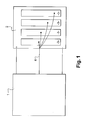
- the electronic system comprises a charging circuit 1 associated with a battery 2.
- the charging circuit 1 can be connected to the main power supply of an application to which the battery 2 is intended for backup or can integrate or be connected to an auxiliary power source to charge the battery of a portable tool.
- the charging circuit 1 can thus control the application of a charging current or maintaining the charge of the battery 2.
- the battery 2 comprises one or more rechargeable electrochemical accumulators 3 with alkaline electrolyte which can be connected in series or in parallel or in series / parallel configuration depending on the nominal operating voltage of the consumer and the quantity of energy (Ampere.hour). ) that it is intended to provide consumer.
- the accumulators 3 can be of any shape, in particular prismatic, cylindrical or concentric.
- the battery 2 further comprises at least one temperature sensor 4 which delivers a signal reflecting the temperature of the battery, this signal being able to be received and analyzed by an electronic unit associated with the charging circuit 1.
- the temperature sensor 4 can be a thermistor, a silicon-based sensor, a thermocouple or any component for obtaining temperature information.
- the battery 2 may comprise a plurality of temperature sensors 4 measuring the temperature of each of the accumulators 3 of the battery 2. The electronic unit associated with the charging circuit 1 can then select as the temperature signal of the battery. battery 2 that corresponding to the accumulator 3 of lower temperature.
- the charging circuit 1 can be any known charging circuit capable of applying a current to the battery 2.
- the charging circuit 1 is capable of applying high currents to achieve a fast charge during the charging phase but also low currents during balancing or load maintenance phases.
- the electronic unit of the charging circuit 1 is adapted to control the application of an overload current.
- overload current is meant the application of a current to the battery while the state of the charge of the battery (SOC) is greater than 95%, or even 100%.
- the method of the invention proposes to apply to the battery 2 an overcharge current when its temperature is below a threshold temperature T 1 in order to heat it.
- the threshold temperature T 1 may correspond, for example, to the minimum temperature of the nominal temperature range of the battery 2.
- the electronic system of the invention operates as follows.
- the electrical unit associated with the charging circuit receives a signal representative of the temperature of the battery 2.
- the signal comes from one of the temperature sensors 4 of the battery 2 or a processing of the different signals from different sensors.
- the electronic unit then makes a comparison between the temperature of the battery 2 and the threshold temperature T 1 predefined. It is also possible that several signals, each corresponding to the temperature of an accumulator 3, are sent to the electronic unit associated with the charging circuit 1 for analysis and comparison with the threshold temperature T 1 ; as the temperature of one of the accumulators 3 is lower than the threshold temperature T 1 , the electronic unit of the charging circuit 2 controls the application of an overcurrent.
- the average overload current applied can be between C / 40 and C / 10, that is to say higher than the current used during the balancing and holding phases of the load but lower than the charging current.
- the overload current ensures sufficient heating.
- the overload current must be chosen according to the most unfavorable case, ie when the difference between the ambient temperature and the threshold temperature T 1 is maximum. It is in this case that a maximum heating and thus a strong current is necessary. For example, in the case of a 10 Ah capacity battery, the overload current can be between 250 mA and 1000 mA.
- the overload current values are only indicative in that these values depend on the battery configuration and the difference between the ambient temperature and the threshold temperature T 1 .
- the battery 2 it is not desirable, however, for the battery 2 to operate beyond the maximum temperature of its nominal temperature range. Indeed, in addition to the deterioration of the performance of the battery 2 when it is used at a too low temperature, charging or discharging at an excessive temperature can also lead to rapid degradation of the components of the battery 2. In some cases , one can observe a thermal runaway of the battery 2, or even its explosion.
- the method and the electronic system of the invention provide that the overcurrent is interrupted when the temperature of the battery 2 exceeds a second threshold temperature T 2 greater than the first threshold temperature T 1 .
- the second threshold temperature T 2 may for example correspond to the minimum value ensuring proper operation of the battery 2 increased by a few degrees.
- an operational amplifier used in a hysteresis circuit can, for example, be used to make comparisons with the first and second threshold temperatures T 1 and T 2 .
- the temperature of the battery 2 may fall below the minimum threshold of good operation; charging circuit 1 then applies a current of overload.
- the temperature of the battery 2 increases accordingly and when the temperature reaches the second threshold temperature T 2 again , the overload current is stopped.
- the battery 2 receives an average overcurrent current controlled by the temperature of the battery 2 to maintain the battery at a temperature within its nominal temperature range and ensure its proper operation.
- the application of the overload current is independent of the currents normally applied by the load circuit 1 (load current, balancing current and load holding current).
- load current normally applied by the load circuit 1
- balancing current and load holding current
- load holding current normally applied by the load circuit 1
- the electronic system of the invention can be used both in a hot environment where the overload current is not useful in a cold environment. Therefore, the electronic system of the invention is particularly well suited to the case of changing environments, especially in the case where the battery 2 is intended to operate outside both in hot weather than in cold weather.
- the existing charging circuits can be relatively easily adapted to include the function of maintaining the temperature of the battery 2. This is particularly the case of electronic systems already incorporating a temperature sensor 4 in the battery 2 and a load management software-driven. To implement the method of the invention, the electronic unit associated with the loader will be programmed with an appropriate load management algorithm.
- This modification of the load management software is done without adding hardware to the existing electronic system in contrast to the solution currently used in the state of the art that requires the addition of a resistive system to heat the battery.
- the invention thus provides a solution to the use of battery in cold environments.
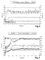
- the figure 2 shows a simulation of the process according to the invention.
- the battery 2 used comprises 30 Ni-MH type accumulators with a capacity of 9.5 Ah in series.
- the experimental conditions of the simulation performed are as follows.
- the system electronics is placed in an oven, for control of the ambient temperature.
- the temperature of the battery 2 is -5 ° C in a temperature oven -9 ° C and the state of charge (SOC) of the battery 2 is 50%.
- the oven is then suddenly set at -18 ° C.
- the time evolution of the system is then studied by measuring the temperature of the battery 2, the temperature of the environment and the voltage of the battery 2.
- the duration of the application phases of the overload and shutdown current depends on the temperature difference between the ambient temperature and the minimum temperature desired for the battery 2.
- the simulation of the figure 3 was performed with the same system that was used for the simulation of the figure 2 .
- the experimental conditions of this second simulation are as follows.
- the electronic system is always in an oven to control the temperature of its environment. However, the oven is set at a lower temperature than in the first simulation, the electronic system is placed in a cardboard box to reduce the effects of forced ventilation of the oven.
- the temperature of the battery 2 is -30 ° C in an oven at -30 ° C and the battery 2 is initially discharged. The battery 2 is then charged.
- the temporal evolution of the system is then studied by measuring the temperature of the battery 2, the temperature of the environment (the ambient temperature is that inside the carton), the voltage of the battery 2 as well as the current of the battery. battery 2.
- the charged battery 2 is maintained at approximately 0 ° C. by the electronic system according to the invention.
- the method and the electronic system of the invention thus allow optimal use of a battery in a cold environment with temperatures below the nominal operating temperature.
Landscapes
- Engineering & Computer Science (AREA)
- Manufacturing & Machinery (AREA)
- Chemical & Material Sciences (AREA)
- Chemical Kinetics & Catalysis (AREA)
- Electrochemistry (AREA)
- General Chemical & Material Sciences (AREA)
- Microelectronics & Electronic Packaging (AREA)
- Power Engineering (AREA)
- Secondary Cells (AREA)
- Charge And Discharge Circuits For Batteries Or The Like (AREA)
Applications Claiming Priority (1)
| Application Number | Priority Date | Filing Date | Title |
|---|---|---|---|
| FR0800097A FR2926165B1 (fr) | 2008-01-08 | 2008-01-08 | Procede de gestion de la charge d'une batterie. |
Publications (3)
| Publication Number | Publication Date |
|---|---|
| EP2079125A2 true EP2079125A2 (de) | 2009-07-15 |
| EP2079125A3 EP2079125A3 (de) | 2012-04-25 |
| EP2079125B1 EP2079125B1 (de) | 2017-10-25 |
Family
ID=39688865
Family Applications (1)
| Application Number | Title | Priority Date | Filing Date |
|---|---|---|---|
| EP08291208.0A Expired - Fee Related EP2079125B1 (de) | 2008-01-08 | 2008-12-18 | Verfahren zur Steuerung des Aufladevorgangs einer Batterie |
Country Status (3)
| Country | Link |
|---|---|
| US (1) | US8237413B2 (de) |
| EP (1) | EP2079125B1 (de) |
| FR (1) | FR2926165B1 (de) |
Cited By (1)
| Publication number | Priority date | Publication date | Assignee | Title |
|---|---|---|---|---|
| FR2974946A1 (fr) * | 2011-05-04 | 2012-11-09 | Peugeot Citroen Automobiles Sa | Dispositif de regeneration d'une batterie |
Families Citing this family (3)
| Publication number | Priority date | Publication date | Assignee | Title |
|---|---|---|---|---|
| FR2970820B1 (fr) | 2011-01-24 | 2013-01-04 | Renault Sa | Procede de gestion de la charge d'une batterie rechargeable d'un vehicule automobile |
| US9585100B2 (en) | 2014-09-02 | 2017-02-28 | Apple Inc. | Cold temperature power throttling at a mobile computing device |
| RU2682894C1 (ru) * | 2018-03-20 | 2019-03-22 | Алексей Гаврилович Речкин | Способ автоматического предотвращения теплового разгона никель-кадмиевой аккумуляторной батареи на борту воздушного судна по температуре аккумуляторной батареи |
Citations (3)
| Publication number | Priority date | Publication date | Assignee | Title |
|---|---|---|---|---|
| FR2282735A1 (fr) | 1974-08-23 | 1976-03-19 | Accumulateurs Fixes | Procede et dispositif de charge a basse temperature pour une batterie d'accumulateurs etanches |
| US5281792A (en) | 1991-08-30 | 1994-01-25 | Rj Lee Group, Inc. | Battery warmer |
| EP1261065A2 (de) | 2001-05-23 | 2002-11-27 | Alcatel | Thermische Verwaltung mittels Abdeckung und Ummantlung von Batteriesystemmodulen |
Family Cites Families (5)
| Publication number | Priority date | Publication date | Assignee | Title |
|---|---|---|---|---|
| US20020101218A1 (en) * | 1984-05-21 | 2002-08-01 | Intermec Ip Corp | Battery pack having memory |
| CA2022802A1 (en) * | 1989-12-05 | 1991-06-06 | Steven E. Koenck | Fast battery charging system and method |
| US20010001533A1 (en) * | 1998-03-24 | 2001-05-24 | Chartec Laboratories A/S | Method and apparatus for charging a rechargeable battery with monitoring of battery temperature rate of change |
| US6307349B1 (en) * | 2000-02-24 | 2001-10-23 | Intermec Ip Corp. | Battery pack having memory |
| CA2363604C (en) * | 2001-11-20 | 2010-04-13 | Edison Source | Method and apparatus for ameliorating electrolyte stratification during rapid charging |
-
2008
- 2008-01-08 FR FR0800097A patent/FR2926165B1/fr not_active Expired - Fee Related
- 2008-12-18 EP EP08291208.0A patent/EP2079125B1/de not_active Expired - Fee Related
-
2009
- 2009-01-07 US US12/349,976 patent/US8237413B2/en not_active Expired - Fee Related
Patent Citations (3)
| Publication number | Priority date | Publication date | Assignee | Title |
|---|---|---|---|---|
| FR2282735A1 (fr) | 1974-08-23 | 1976-03-19 | Accumulateurs Fixes | Procede et dispositif de charge a basse temperature pour une batterie d'accumulateurs etanches |
| US5281792A (en) | 1991-08-30 | 1994-01-25 | Rj Lee Group, Inc. | Battery warmer |
| EP1261065A2 (de) | 2001-05-23 | 2002-11-27 | Alcatel | Thermische Verwaltung mittels Abdeckung und Ummantlung von Batteriesystemmodulen |
Cited By (1)
| Publication number | Priority date | Publication date | Assignee | Title |
|---|---|---|---|---|
| FR2974946A1 (fr) * | 2011-05-04 | 2012-11-09 | Peugeot Citroen Automobiles Sa | Dispositif de regeneration d'une batterie |
Also Published As
| Publication number | Publication date |
|---|---|
| US20090174368A1 (en) | 2009-07-09 |
| FR2926165B1 (fr) | 2010-11-05 |
| US8237413B2 (en) | 2012-08-07 |
| EP2079125A3 (de) | 2012-04-25 |
| EP2079125B1 (de) | 2017-10-25 |
| FR2926165A1 (fr) | 2009-07-10 |
Similar Documents
| Publication | Publication Date | Title |
|---|---|---|
| EP3191337B1 (de) | Verfahren zur verwaltung des betriebsbereichs einer batterie | |
| EP1685622B1 (de) | Gleichgewichts-ladeverfahren für eine lithiumionen- oder lithiumpolymerbatterie | |
| EP1854165B3 (de) | Verfahren zum ausgewogenen aufladen einer lithiumionen- oder lithium-polymer-batterie | |
| EP3490099B1 (de) | Architektur von parallel geschalteten batteriemodulen | |
| EP2085268B1 (de) | Elektronisches System für Batterie | |
| EP2600462B1 (de) | Verfahren zum Ausgleich von Spannungen elektrischer Elemente, die auf mehreren parallelen Zweigen angeordnet sind | |
| EP1774353A1 (de) | Verfahren zur akkuspeicherverwaltung | |
| FR2704982A1 (fr) | Système de reconnaissance et de gestion de générateurs électrochimiques. | |
| FR3002045A1 (fr) | Gestion de la charge d'une batterie | |
| EP0498715B1 (de) | Verfahren zur Ladungsoptimierung einer Akkumulatorenbatterie und Vorrichtung zu dessen Durchführung | |
| EP2079125B1 (de) | Verfahren zur Steuerung des Aufladevorgangs einer Batterie | |
| FR3006812A1 (fr) | Gestion de la duree de vie d'une batterie | |
| EP3096974A1 (de) | Verfahren zur verwaltung eines ladezustands einer batterie | |
| EP2309615B1 (de) | System und Verfahren zur Steuerung des Aufladevorgangs einer Batterie | |
| EP2237387B1 (de) | Power supply system and charging control method for electrochemical generators | |
| FR2714772A1 (fr) | Perfectionnements apportés à des batteries d'alimentation. | |
| FR2636479A1 (fr) | Procede de charge ultrarapide pour accumulateur cadmium-nickel etanche | |
| EP2076953A2 (de) | Verfahren zur kontrolle des entladungsendes eines akkus | |
| FR2916578A1 (fr) | Systeme electronique pour batterie. | |
| FR2849298A1 (fr) | Dispositif de controle de l'etat de charge, a tension constante, d'un ensemble de batterie a generateurs electrochimiques secondaires | |
| EP3672024A1 (de) | Vorrichtung und verfahren zum steuern der aufladung und entladung von batterien einer gruppe solcher batterien | |
| FR2970384A1 (fr) | Gestion de batteries electriques |
Legal Events
| Date | Code | Title | Description |
|---|---|---|---|
| PUAI | Public reference made under article 153(3) epc to a published international application that has entered the european phase |
Free format text: ORIGINAL CODE: 0009012 |
|
| AK | Designated contracting states |
Kind code of ref document: A2 Designated state(s): AT BE BG CH CY CZ DE DK EE ES FI FR GB GR HR HU IE IS IT LI LT LU LV MC MT NL NO PL PT RO SE SI SK TR |
|
| AX | Request for extension of the european patent |
Extension state: AL BA MK RS |
|
| PUAL | Search report despatched |
Free format text: ORIGINAL CODE: 0009013 |
|
| AK | Designated contracting states |
Kind code of ref document: A3 Designated state(s): AT BE BG CH CY CZ DE DK EE ES FI FR GB GR HR HU IE IS IT LI LT LU LV MC MT NL NO PL PT RO SE SI SK TR |
|
| AX | Request for extension of the european patent |
Extension state: AL BA MK RS |
|
| RIC1 | Information provided on ipc code assigned before grant |
Ipc: H01M 10/24 20060101ALN20120320BHEP Ipc: H01M 10/44 20060101ALI20120320BHEP Ipc: H01M 10/34 20060101AFI20120320BHEP Ipc: H01M 10/46 20060101ALI20120320BHEP Ipc: H01M 10/42 20060101ALN20120320BHEP |
|
| 17P | Request for examination filed |
Effective date: 20121025 |
|
| AKX | Designation fees paid |
Designated state(s): DE FR GB |
|
| 17Q | First examination report despatched |
Effective date: 20130130 |
|
| RAP1 | Party data changed (applicant data changed or rights of an application transferred) |
Owner name: ARTS ENERGY |
|
| GRAP | Despatch of communication of intention to grant a patent |
Free format text: ORIGINAL CODE: EPIDOSNIGR1 |
|
| STAA | Information on the status of an ep patent application or granted ep patent |
Free format text: STATUS: GRANT OF PATENT IS INTENDED |
|
| RIC1 | Information provided on ipc code assigned before grant |
Ipc: H01M 10/24 20060101ALN20170502BHEP Ipc: H01M 10/42 20060101ALN20170502BHEP Ipc: H01M 10/46 20060101ALI20170502BHEP Ipc: H01M 10/44 20060101ALI20170502BHEP Ipc: H01M 10/34 20060101AFI20170502BHEP |
|
| INTG | Intention to grant announced |
Effective date: 20170523 |
|
| GRAS | Grant fee paid |
Free format text: ORIGINAL CODE: EPIDOSNIGR3 |
|
| GRAA | (expected) grant |
Free format text: ORIGINAL CODE: 0009210 |
|
| STAA | Information on the status of an ep patent application or granted ep patent |
Free format text: STATUS: THE PATENT HAS BEEN GRANTED |
|
| AK | Designated contracting states |
Kind code of ref document: B1 Designated state(s): DE FR GB |
|
| REG | Reference to a national code |
Ref country code: GB Ref legal event code: FG4D Free format text: NOT ENGLISH |
|
| REG | Reference to a national code |
Ref country code: DE Ref legal event code: R096 Ref document number: 602008052627 Country of ref document: DE |
|
| REG | Reference to a national code |
Ref country code: FR Ref legal event code: PLFP Year of fee payment: 10 |
|
| REG | Reference to a national code |
Ref country code: DE Ref legal event code: R097 Ref document number: 602008052627 Country of ref document: DE |
|
| PLBE | No opposition filed within time limit |
Free format text: ORIGINAL CODE: 0009261 |
|
| STAA | Information on the status of an ep patent application or granted ep patent |
Free format text: STATUS: NO OPPOSITION FILED WITHIN TIME LIMIT |
|
| 26N | No opposition filed |
Effective date: 20180726 |
|
| PGFP | Annual fee paid to national office [announced via postgrant information from national office to epo] |
Ref country code: GB Payment date: 20181228 Year of fee payment: 11 Ref country code: FR Payment date: 20181130 Year of fee payment: 11 |
|
| PGFP | Annual fee paid to national office [announced via postgrant information from national office to epo] |
Ref country code: DE Payment date: 20181221 Year of fee payment: 11 |
|
| REG | Reference to a national code |
Ref country code: DE Ref legal event code: R119 Ref document number: 602008052627 Country of ref document: DE |
|
| GBPC | Gb: european patent ceased through non-payment of renewal fee |
Effective date: 20191218 |
|
| PG25 | Lapsed in a contracting state [announced via postgrant information from national office to epo] |
Ref country code: FR Free format text: LAPSE BECAUSE OF NON-PAYMENT OF DUE FEES Effective date: 20191231 Ref country code: DE Free format text: LAPSE BECAUSE OF NON-PAYMENT OF DUE FEES Effective date: 20200701 Ref country code: GB Free format text: LAPSE BECAUSE OF NON-PAYMENT OF DUE FEES Effective date: 20191218 |