EP2078636A2 - Improvements in or relating to in-vehicle luggage systems - Google Patents
Improvements in or relating to in-vehicle luggage systems Download PDFInfo
- Publication number
- EP2078636A2 EP2078636A2 EP08172222A EP08172222A EP2078636A2 EP 2078636 A2 EP2078636 A2 EP 2078636A2 EP 08172222 A EP08172222 A EP 08172222A EP 08172222 A EP08172222 A EP 08172222A EP 2078636 A2 EP2078636 A2 EP 2078636A2
- Authority
- EP
- European Patent Office
- Prior art keywords
- luggage
- board
- mounting bracket
- luggage system
- seat
- Prior art date
- Legal status (The legal status is an assumption and is not a legal conclusion. Google has not performed a legal analysis and makes no representation as to the accuracy of the status listed.)
- Granted
Links
Images


Classifications
-
- B—PERFORMING OPERATIONS; TRANSPORTING
- B60—VEHICLES IN GENERAL
- B60R—VEHICLES, VEHICLE FITTINGS, OR VEHICLE PARTS, NOT OTHERWISE PROVIDED FOR
- B60R5/00—Compartments within vehicle body primarily intended or sufficiently spacious for trunks, suit-cases, or the like
- B60R5/04—Compartments within vehicle body primarily intended or sufficiently spacious for trunks, suit-cases, or the like arranged at rear of vehicle
-
- B—PERFORMING OPERATIONS; TRANSPORTING
- B60—VEHICLES IN GENERAL
- B60N—SEATS SPECIALLY ADAPTED FOR VEHICLES; VEHICLE PASSENGER ACCOMMODATION NOT OTHERWISE PROVIDED FOR
- B60N2/00—Seats specially adapted for vehicles; Arrangement or mounting of seats in vehicles
- B60N2/24—Seats specially adapted for vehicles; Arrangement or mounting of seats in vehicles for particular purposes or particular vehicles
- B60N2/32—Seats specially adapted for vehicles; Arrangement or mounting of seats in vehicles for particular purposes or particular vehicles convertible for other use
- B60N2/36—Seats specially adapted for vehicles; Arrangement or mounting of seats in vehicles for particular purposes or particular vehicles convertible for other use into a loading platform
- B60N2002/363—Seats specially adapted for vehicles; Arrangement or mounting of seats in vehicles for particular purposes or particular vehicles convertible for other use into a loading platform characterised by provisions for enhancing the cargo floor surface, e.g. elements closing gaps or enlarging the back-rest surface
Definitions
- the present invention relates to a luggage system for use in a vehicle and, in particular, to a luggage system for use in a vehicle with a suspended floor.
- the rear luggage compartment within a vehicle i.e. the volume of space that lies behind the rearmost seating row, provides a considerable volume of storage space.
- a vehicle i.e. the volume of space that lies behind the rearmost seating row
- the mountings for these storage boards can be mounted on the interior trim.
- the interior trim is typically only a single thickness piece and therefore, under heavy braking, a load can impinge on a vertically mounted luggage board with sufficient force to damage the mountings and the interior trim.
- a luggage system for use in a vehicle comprising at least one seat mounted on a seat frame, the luggage system comprising: at least one mounting bracket comprising a recess for holding a luggage board in a substantially vertical position; and wherein the mounting bracket is mounted to the seat frame.
- the luggage system does not compromise the access any under floor storage capacity. Furthermore, the operation of the luggage system is also independent of the tilt angle of each of the seats.
- the luggage system may further comprise a luggage board.
- the mounting bracket may be further configured to permit the luggage board to be retained in a substantially horizontal position.
- the mounting bracket may be provided with a flat upper surface on which the luggage board rests when it is in the horizontal position.
- the vehicle may be provided with a ledge that is configured to interface with a part of the luggage board to maintain the board in a substantially horizontal configuration.
- the advantage of the luggage board taking a horizontal configuration is that it provides for a flat luggage compartment floor. As this luggage compartment floor would not naturally be flat, the horizontal position of the luggage board divides out a lower volume of the luggage compartment the contents of which are hidden from view.
- the luggage board may be carpet covered and has a light, honeycomb core.
- the carpet covering ensures that the interface between the board and the mounting bracket does not rattle and the light honeycomb core ensures that the board is light and therefore easily manipulated in a one handed operation.
- the recess may be U-shaped and it may further have non-parallel wall.
- the non-parallel walls guide the luggage board into the recess.
- the luggage board may have a front edge that is tapered in order to interface with the walls of the U-shaped recess.
- the tapered edge of the luggage board increases the area of the board that interfaces with the walls of the recess.
- the angle of taper of the back edge of the luggage board may be different from the angle between the non-parallel walls of the recess. The angles are deliberately different to provide a pinched interface that will not squeak.
- the luggage system may further comprise a cover board and an anchor point on the mounting bracket for pivotable mounting of the cover board.
- the cover board ensures that there is never a gap between the luggage board and the back of the seat, regardless of whether the seats are in the folded-flat or the up-right, in use position.
- mounting brackets There may be two mounting brackets.
- One mounting bracket may be positioned at each side of the vehicle, mounted on the outboard side of the seat frame. The provision of two mounting brackets provides a stable system that is not easily subject to rotation of the luggage board.
- a third mounting bracket may be provided approximately equidistant between the two mounting brackets. This provides additional reinforcement for the luggage board when it is in the horizontal configuration and prevents it from bending.
- the seat frame may be further configured to move between a first in-use position and a second position and, wherein the mounting bracket is arranged to move with the seat.
- Figure 1 shows the second 20 and third 30 row seating and plate luggage rear 70 within a vehicle 100 comprising three seating rows.
- the third row 30 comprises a pair of occasional use seats that are configured to be foldable between an in-use position shown in Figures 3 and 4 and the stowed position shown in Figure 1 .
- Each of the seats comprises a seat frame concealed within a seat base 34 and a seat back 36.
- the third row seating 30 is configured so that the seat back 36 folds relative to the seat base 34 until the seat back 36 is substantially horizontal.
- the terms “horizontal” and “vertical” are used to describe the position of the various components of the system 10. It will be readily apparent to the skilled man, that the terms “horizontal” and “vertical” are not intended to set precisely the angles between the components, but rather to give a feel for the overall orientation of a component. For example, when the seat back is in a vertical condition, it is typically inclined at around 14° to the vertical.
- the luggage system 10 further comprises a luggage board 40, a mounting bracket 50 and a cover board 60.
- the luggage board 40 is a light yet strong board made using, for example, a honeycomb cardboard impregnated with Polyurethane.
- the luggage board 40 is covered in carpet.
- the carpet ensures that the luggage board 40 does not squeak or rattle as a result of small movements of the board 40 relative to the other components of the system 10.
- the carpet also improves the perceived quality of the luggage board 40.
- the luggage board 40 has a front edge 42 which is tapered in order that it can interface with the mounting bracket 50 when the luggage board 40 is in a vertical configuration.
- the luggage board 40 also has a rear edge 44 that is curved to match the profile of the inner edge of the plate luggage rear 70.
- the luggage board 40 also has two side edges 48 that are substantially orthogonal to the front 44 and back 42 edges.
- the luggage board 40 is also provided with a handle 46.
- the handle 46 consists of an oval shaped through-hole that is sized to accommodate the hand of the average user.
- the handle 46 is positioned close to the rear edge 44 of the luggage board so the handle 46 is easily accessible.
- the handle 46 is also positioned equidistant from the two side edges 48. The central positioning of the handle 46 ensures that the user can move the board 40 in a one-handed operation as the board 40 is balanced when it is lifted by the handle 46.
- a mounting bracket 50 is attached to the seat frame.
- the mounting bracket 50 includes a U-shaped recess 52 into which the board 40 can be mounted when the board 40 is placed in the vertical configuration as shown in Figures 5 to 8 .
- the U-shaped recess has two walls 54, 56 which are not parallel.
- the walls 54, 56 are tapered so that, as the luggage board 40 is inserted into the recess the front edge 42 of the luggage board 40 is pinched by the walls 54, 56 of the recess 52.
- the angle of taper of the walls 54, 56 is different from the angle of taper of the front edge 42 of the luggage board.
- the front edge 42 of the luggage board has an angle of taper of 2° to 5°. In particular, the front edge 42 of the luggage board has an angle of taper of 3°.
- the tapered shape of the U-shaped recess 52 also guides the board 40 into the mounting bracket 50.
- the mounting bracket 50 has a flat upper surface 53. When the luggage board 40 is in the horizontal configuration, the front edge 42 of the luggage board rests on the upper surface 53 of the mounting bracket 50.
- the mounting bracket 50 also includes an anchor point 58 for the cover board 60.
- the anchor point 58 provides a pivotable attachment for the cover board 60.
- the anchor point 58 is provided by a box-section portion 59 that is adjacent to the wall 54.
- the ledge 71 provides a horizontal surface for the rear edge 44 to rest on and a vertical surface against which the rear edge 44 abuts. This is most apparent in Figure 4 .
- the horizontal surface of the ledge 71 is situated below the level of plate luggage rear 70 by approximately the distance corresponding to the thickness of the luggage board 40 so that, when the rear edge 44 is resting on the ledge, the upper surface of the luggage board is substantially flush with the plate luggage rear 70. This facilitates the user sliding luggage straight into the luggage compartment.
- One mounting bracket 50 is mounted on the seat frame at, or near to, each side of the vehicle 100.
- a third mounting bracket 50 is positioned approximately half way between the two mounting brackets.
- the cover board 60 is pivotably attached to the mounting bracket 50 by the anchor point 58.
- the cover board 60 is a light, thin board that is intended to cover the join between the seat backs 36 and the luggage board 40.
- the cover board is substantially vertical.
- the cover board also adopts a horizontal position, still in contact with a part of the seat back 36. In each case, the cover board 60 prevents any small loose items within the luggage area from moving under the seats 30.
- the luggage board 40 when the third row seats 30 are stowed and the luggage board 40 is in the horizontal configuration, the luggage board is prevented from moving because it abuts the box-section portion 59 and the vertical surface of the plate luggage rear ledge 71.
- the luggage board 40, cover board 60 and the back surface of the seat back 36 provide a continuous, substantially horizontal surface that is flush with the plate luggage rear 70. This makes it easy for the user to slide items into the luggage compartment without having to lift them over a sill.
- the luggage board 40 is prevented from movement in the vertical plane because the front edge 42 rests on the upper surface of the U-shaped recess and the back edge 44 rests on a the ledge 71 that is provided on the forward vertical surface of the plate luggage rear 70.
- an additional volume 80 of storage space is available beneath the luggage board 40.
- This volume 80 is accessed by lifting the luggage board 40 or pivoting it around the abutment between the back edge of the luggage board 40 and the box-section portion 59.
- This volume 80 is particularly useful for stowing items when the vehicle is left unattended as the items stowed within this area cannot be seen from outside the vehicle 100.
- FIGs 5 to 8 show the luggage board 40 in the vertical configuration.
- the luggage board 40 is held in place as a result of the U-shaped recess 52 of the mounting bracket 50 pinching the front edge 42 of the luggage board 40.
- the volume 80 is combined with the volume above in order to accommodate a tall item 90 of luggage, as shown in Figure 6 .
- the luggage board 40 can be mounted in either the horizontal or the vertical configuration regardless of the position of the seat 30. Indeed, as shown in Figure 6 , the luggage board 40 can be placed in the vertical configuration in order to accommodate a tall item 90 of luggage and, in addition, to constrain the movement of that item so that the portion of the luggage compartment above the folded third row seats can be used to stow other items that need to be kept separate from the large item 90.
- the vehicle 100 has a suspended floor and, beneath the suspended floor, is an area in which a space-saver spare wheel is stowed. Because the mounting bracket 50 is attached to the seat frame and the seat 30 is configured to tip and tumble, the seat can pivot about a point close to the front of the seat base thus lifting the rear portion of the seat base and the mounting bracket to allow access to the space beneath the seat in which the space-saver spare wheel is stowed.
Abstract
Description
- The present invention relates to a luggage system for use in a vehicle and, in particular, to a luggage system for use in a vehicle with a suspended floor.
- The rear luggage compartment within a vehicle, i.e. the volume of space that lies behind the rearmost seating row, provides a considerable volume of storage space. Especially in a MPV or SUV-type vehicle, there is typically a considerable height available which facilitates the easy stowage of large items, such as suitcases.
- It is common for vehicle manufacturers to provide some means by which the luggage compartment may be subdivided as it is acknowledged that some cargoes can be damaged in transit if they remain unrestrained within the comparatively large area of the luggage compartment. To this end, manufacturers have provided a variety of fixed shelves and boxes that are ideally suited for carrying a plurality of small items. However, the problem with these systems is that they are inflexible and can compromise the carrying capability for larger items.
- In order to provide increased flexibility some manufacturers have provided one or more storage boards and a selection of mounting assemblies that allow the board or boards to be mounted in a number of different positions, including vertical and horizontal partitioning of the available space.
- The mountings for these storage boards can be mounted on the interior trim. However, the interior trim is typically only a single thickness piece and therefore, under heavy braking, a load can impinge on a vertically mounted luggage board with sufficient force to damage the mountings and the interior trim.
- It is against this background that the present invention has been made.
- According to the present invention there is provided a luggage system for use in a vehicle comprising at least one seat mounted on a seat frame, the luggage system comprising: at least one mounting bracket comprising a recess for holding a luggage board in a substantially vertical position; and wherein the mounting bracket is mounted to the seat frame.
- By mounting the bracket on the seat frame, rather than on the seat back or on the vehicle floor, the luggage system does not compromise the access any under floor storage capacity. Furthermore, the operation of the luggage system is also independent of the tilt angle of each of the seats.
- The luggage system may further comprise a luggage board. The mounting bracket may be further configured to permit the luggage board to be retained in a substantially horizontal position.
- In particular, the mounting bracket may be provided with a flat upper surface on which the luggage board rests when it is in the horizontal position. Furthermore, the vehicle may be provided with a ledge that is configured to interface with a part of the luggage board to maintain the board in a substantially horizontal configuration.
- The advantage of the luggage board taking a horizontal configuration is that it provides for a flat luggage compartment floor. As this luggage compartment floor would not naturally be flat, the horizontal position of the luggage board divides out a lower volume of the luggage compartment the contents of which are hidden from view.
- The luggage board may be carpet covered and has a light, honeycomb core. The carpet covering ensures that the interface between the board and the mounting bracket does not rattle and the light honeycomb core ensures that the board is light and therefore easily manipulated in a one handed operation.
- The recess may be U-shaped and it may further have non-parallel wall. The non-parallel walls guide the luggage board into the recess.
- The luggage board may have a front edge that is tapered in order to interface with the walls of the U-shaped recess. The tapered edge of the luggage board increases the area of the board that interfaces with the walls of the recess.
- The angle of taper of the back edge of the luggage board may be different from the angle between the non-parallel walls of the recess. The angles are deliberately different to provide a pinched interface that will not squeak.
- The luggage system may further comprise a cover board and an anchor point on the mounting bracket for pivotable mounting of the cover board. The cover board ensures that there is never a gap between the luggage board and the back of the seat, regardless of whether the seats are in the folded-flat or the up-right, in use position.
- There may be two mounting brackets. One mounting bracket may be positioned at each side of the vehicle, mounted on the outboard side of the seat frame. The provision of two mounting brackets provides a stable system that is not easily subject to rotation of the luggage board.
- A third mounting bracket may be provided approximately equidistant between the two mounting brackets. This provides additional reinforcement for the luggage board when it is in the horizontal configuration and prevents it from bending.
- The seat frame may be further configured to move between a first in-use position and a second position and, wherein the mounting bracket is arranged to move with the seat. This provides the user with a luggage system that moves with the seat and can conveniently hold the luggage board irrespective of seat position. In this way, if the vehicle is provided with storage beneath the seat is may be accessed by placing the luggage board into the mounting bracket and moving the seat to a convenient position to access the storage area.
- The present invention will now be described with reference, by way of example only, to the accompanying drawings in which:
-
Figures 1 to 4 show the luggage system and mounting bracket of the present invention with a luggage board in a horizontal configuration; -
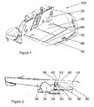
Figure 1 shows the luggage system providing the maximum luggage storage space over a flat bed; -
Figure 2 is a cross sectional view through the luggage system when configured as shown inFigure 1 ; -
Figure 3 shows the luggage system configured to allow the maximum number of available seats within the vehicle to be used; and -
Figure 4 shows a cross section through the luggage system in the configuration shown inFigure 3 . -
Figures 5 to 8 show the luggage system and mounting bracket of the present invention with a luggage board in a vertical configuration; -
Figure 5 shows the luggage system providing a divided luggage storage space; -
Figure 6 is a cross sectional view through the luggage system when configured as shown inFigure 5 ; -
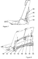
Figure 7 is a side view of the luggage system configured to allow the maximum number of available seats within the vehicle to be used; -
Figure 8 is a part perspective view of the configuration shown inFigure 7 . -
Figure 1 shows the second 20 and third 30 row seating and plate luggage rear 70 within avehicle 100 comprising three seating rows. Thethird row 30 comprises a pair of occasional use seats that are configured to be foldable between an in-use position shown inFigures 3 and 4 and the stowed position shown inFigure 1 . Each of the seats comprises a seat frame concealed within aseat base 34 and a seat back 36. - The
third row seating 30 is configured so that the seat back 36 folds relative to theseat base 34 until theseat back 36 is substantially horizontal. Throughout the description, the terms "horizontal" and "vertical" are used to describe the position of the various components of the system 10. It will be readily apparent to the skilled man, that the terms "horizontal" and "vertical" are not intended to set precisely the angles between the components, but rather to give a feel for the overall orientation of a component. For example, when the seat back is in a vertical condition, it is typically inclined at around 14° to the vertical. - The luggage system 10 further comprises a
luggage board 40, amounting bracket 50 and acover board 60. Theluggage board 40 is a light yet strong board made using, for example, a honeycomb cardboard impregnated with Polyurethane. - The
luggage board 40 is covered in carpet. The carpet ensures that theluggage board 40 does not squeak or rattle as a result of small movements of theboard 40 relative to the other components of the system 10. The carpet also improves the perceived quality of theluggage board 40. Theluggage board 40 has afront edge 42 which is tapered in order that it can interface with themounting bracket 50 when theluggage board 40 is in a vertical configuration. Theluggage board 40 also has arear edge 44 that is curved to match the profile of the inner edge of theplate luggage rear 70. Theluggage board 40 also has twoside edges 48 that are substantially orthogonal to thefront 44 and back 42 edges. - The
luggage board 40 is also provided with ahandle 46. Thehandle 46 consists of an oval shaped through-hole that is sized to accommodate the hand of the average user. Thehandle 46 is positioned close to therear edge 44 of the luggage board so thehandle 46 is easily accessible. Thehandle 46 is also positioned equidistant from the two side edges 48. The central positioning of thehandle 46 ensures that the user can move theboard 40 in a one-handed operation as theboard 40 is balanced when it is lifted by thehandle 46. - A mounting
bracket 50 is attached to the seat frame. The mountingbracket 50 includes aU-shaped recess 52 into which theboard 40 can be mounted when theboard 40 is placed in the vertical configuration as shown inFigures 5 to 8 . The U-shaped recess has twowalls walls luggage board 40 is inserted into the recess thefront edge 42 of theluggage board 40 is pinched by thewalls recess 52. The angle of taper of thewalls front edge 42 of the luggage board. Thefront edge 42 of the luggage board has an angle of taper of 2° to 5°. In particular, thefront edge 42 of the luggage board has an angle of taper of 3°. The tapered shape of theU-shaped recess 52 also guides theboard 40 into the mountingbracket 50. - The mounting
bracket 50 has a flatupper surface 53. When theluggage board 40 is in the horizontal configuration, thefront edge 42 of the luggage board rests on theupper surface 53 of the mountingbracket 50. - The mounting
bracket 50 also includes ananchor point 58 for thecover board 60. Theanchor point 58 provides a pivotable attachment for thecover board 60. In this example, theanchor point 58 is provided by a box-section portion 59 that is adjacent to thewall 54. When theluggage board 40 is in the horizontal configuration, thefront edge 42 abuts the box-section portion 59 and therear edge 44 rests on a ledge 71 provided in the plate luggage rear 70. - The ledge 71 provides a horizontal surface for the
rear edge 44 to rest on and a vertical surface against which therear edge 44 abuts. This is most apparent inFigure 4 . The horizontal surface of the ledge 71 is situated below the level of plate luggage rear 70 by approximately the distance corresponding to the thickness of theluggage board 40 so that, when therear edge 44 is resting on the ledge, the upper surface of the luggage board is substantially flush with the plate luggage rear 70. This facilitates the user sliding luggage straight into the luggage compartment. - One mounting
bracket 50 is mounted on the seat frame at, or near to, each side of thevehicle 100. In addition, athird mounting bracket 50 is positioned approximately half way between the two mounting brackets. - The
cover board 60 is pivotably attached to the mountingbracket 50 by theanchor point 58. Thecover board 60 is a light, thin board that is intended to cover the join between the seat backs 36 and theluggage board 40. When the third row seats 30 are in use, as shown inFigures 5 to 8 , the cover board is substantially vertical. When the third row seats are tipped forward into the stowed position, the cover board also adopts a horizontal position, still in contact with a part of the seat back 36. In each case, thecover board 60 prevents any small loose items within the luggage area from moving under theseats 30. - As shown in
Figure 2 , when the third row seats 30 are stowed and theluggage board 40 is in the horizontal configuration, the luggage board is prevented from moving because it abuts the box-section portion 59 and the vertical surface of the plate luggage rear ledge 71. Theluggage board 40,cover board 60 and the back surface of the seat back 36 provide a continuous, substantially horizontal surface that is flush with the plate luggage rear 70. This makes it easy for the user to slide items into the luggage compartment without having to lift them over a sill. - The
luggage board 40 is prevented from movement in the vertical plane because thefront edge 42 rests on the upper surface of the U-shaped recess and theback edge 44 rests on a the ledge 71 that is provided on the forward vertical surface of the plate luggage rear 70. - Furthermore, it will be readily apparent from
Figure 2 that anadditional volume 80 of storage space is available beneath theluggage board 40. Thisvolume 80 is accessed by lifting theluggage board 40 or pivoting it around the abutment between the back edge of theluggage board 40 and the box-section portion 59. Thisvolume 80 is particularly useful for stowing items when the vehicle is left unattended as the items stowed within this area cannot be seen from outside thevehicle 100. -
Figures 5 to 8 show theluggage board 40 in the vertical configuration. In this configuration, theluggage board 40 is held in place as a result of theU-shaped recess 52 of the mountingbracket 50 pinching thefront edge 42 of theluggage board 40. In this configuration thevolume 80 is combined with the volume above in order to accommodate atall item 90 of luggage, as shown inFigure 6 . - Because the mounting
bracket 50 is positioned on the seat frame and not on the seat back, theluggage board 40 can be mounted in either the horizontal or the vertical configuration regardless of the position of theseat 30. Indeed, as shown inFigure 6 , theluggage board 40 can be placed in the vertical configuration in order to accommodate atall item 90 of luggage and, in addition, to constrain the movement of that item so that the portion of the luggage compartment above the folded third row seats can be used to stow other items that need to be kept separate from thelarge item 90. - The
vehicle 100 has a suspended floor and, beneath the suspended floor, is an area in which a space-saver spare wheel is stowed. Because the mountingbracket 50 is attached to the seat frame and theseat 30 is configured to tip and tumble, the seat can pivot about a point close to the front of the seat base thus lifting the rear portion of the seat base and the mounting bracket to allow access to the space beneath the seat in which the space-saver spare wheel is stowed. - Although the present invention has been described hereinabove with reference to a three row seating configuration, the skilled man will appreciate that it is not limited to use in vehicles with a three row seating configuration. Indeed, it is applicable to any vehicle that has a suspended floor and a requirement to subdivide the luggage compartment without compromising the access to a spare wheel stowed beneath the suspended floor.
Claims (12)
- A luggage system for use in a vehicle comprising at least one seat mounted on a seat frame, the luggage system comprising:at least one mounting bracket comprising a recess for holding a luggage board in a substantially vertical position; andwherein the mounting bracket is mounted to the seat frame.
- The luggage system according to claim 1, further comprising a luggage board.
- The luggage system according to claim 2, wherein the mounting bracket is further configured to permit the luggage board to be retained in a substantially horizontal position.
- The luggage system according to claim 2 or claim 3, wherein the luggage board is carpet covered and has a light, honeycomb core.
- The luggage system according to any one of claims 1 to 4, wherein the recess is U-shaped.
- The luggage system according to any one of claims 1 to 5, wherein the recess has non-parallel walls.
- The luggage system according to any one of claims 2 to 6, wherein the luggage board has a back edge that is tapered in order to interface with the walls of the U-shaped recess.
- The luggage system according to claim 7, wherein the angle of taper of the back edge of the luggage board is different from the angle between the non-parallel walls of the recess.
- The luggage system according to any one of the preceding claims, further comprising a cover board and an anchor point on the mounting bracket for pivotable mounting of the cover board.
- The luggage system according to any one of the preceding claims, wherein there are two mounting brackets.
- The luggage system according to claim 10, further comprising a third mounting bracket.
- The luggage system according to any one of the preceding claims, wherein the seat frame is configured to move between a first in-use position and a second position and, wherein the mounting bracket is arranged to move with the seat.
Applications Claiming Priority (1)
| Application Number | Priority Date | Filing Date | Title |
|---|---|---|---|
| GB0800558A GB2456345B (en) | 2008-01-14 | 2008-01-14 | Improvements in or relating to in-vehicle luggage systems |
Publications (3)
| Publication Number | Publication Date |
|---|---|
| EP2078636A2 true EP2078636A2 (en) | 2009-07-15 |
| EP2078636A3 EP2078636A3 (en) | 2010-12-08 |
| EP2078636B1 EP2078636B1 (en) | 2013-12-18 |
Family
ID=39144847
Family Applications (1)
| Application Number | Title | Priority Date | Filing Date |
|---|---|---|---|
| EP08172222.5A Expired - Fee Related EP2078636B1 (en) | 2008-01-14 | 2008-12-19 | Improvements in or relating to in-vehicle luggage systems |
Country Status (3)
| Country | Link |
|---|---|
| EP (1) | EP2078636B1 (en) |
| ES (1) | ES2445046T3 (en) |
| GB (1) | GB2456345B (en) |
Cited By (5)
| Publication number | Priority date | Publication date | Assignee | Title |
|---|---|---|---|---|
| CN102785622A (en) * | 2011-05-20 | 2012-11-21 | 丰田纺织株式会社 | Interior decoration piece of luggage case |
| RU2500552C1 (en) * | 2011-06-29 | 2013-12-10 | Форд Глобал Технолоджис, ЛЛК | System of seats with luggage rack |
| GB2512852A (en) * | 2013-04-09 | 2014-10-15 | Nissan Motor Mfg Uk Ltd | Vehicle Boot |
| CN109515525A (en) * | 2018-11-02 | 2019-03-26 | 靖江市新程汽车零部件有限公司 | A kind of automobile-used lightweight luggage boot partition of car and production technology |
| DE102020107163A1 (en) | 2020-03-16 | 2021-09-16 | Ford Global Technologies Llc | Loading floor arrangement for a motor vehicle |
Families Citing this family (5)
| Publication number | Priority date | Publication date | Assignee | Title |
|---|---|---|---|---|
| US8505999B2 (en) | 2009-06-29 | 2013-08-13 | Honda Motor Company, Ltd. | Vehicular seat assembly and vehicles including same |
| DE102010052455A1 (en) * | 2010-11-24 | 2012-05-24 | GM Global Technology Operations LLC | Motor vehicle i.e. passenger car, has cover for closing storage box, and flap for covering retaining area, where cover and flap form loading bottom sections in horizontal position and connected with one another by flexible connection |
| US8905276B2 (en) * | 2011-12-19 | 2014-12-09 | Havis, Inc. | Mounting and storage system affixed to the floor of a vehicle trunk and method for mounting a device thereon |
| ES2537931B2 (en) * | 2013-12-13 | 2015-10-01 | Seat, S.A. | Trunk with adjustable floor for vehicle |
| CN117584858B (en) * | 2024-01-19 | 2024-03-19 | 中创优品汽车科技(江苏)有限公司 | Telescopic storage device for automobile trunk |
Citations (3)
| Publication number | Priority date | Publication date | Assignee | Title |
|---|---|---|---|---|
| US20060061120A1 (en) * | 2004-08-06 | 2006-03-23 | Czerwinski Kenneth J | Flipper panel for a vehicle |
| JP2006335096A (en) * | 2005-05-31 | 2006-12-14 | Mazda Motor Corp | Rear vehicle body structure of vehicle |
| JP2008265708A (en) * | 2007-04-25 | 2008-11-06 | Suzuki Motor Corp | Luggage board support structure |
Family Cites Families (5)
| Publication number | Priority date | Publication date | Assignee | Title |
|---|---|---|---|---|
| JPS6033693B2 (en) * | 1981-08-05 | 1985-08-05 | 日産自動車株式会社 | Structure of retractable rear parcel shelf |
| FR2875454B1 (en) * | 2004-09-22 | 2008-02-01 | Peugeot Citroen Automobiles Sa | REAR SHELF FOR A MOTOR VEHICLE AND A MOTOR VEHICLE EQUIPPED WITH SUCH A TABLET |
| FR2877292B1 (en) * | 2004-10-28 | 2007-04-06 | Renault Sas | FOLDING SHELF FOR A TAILGATE OF A MOTOR VEHICLE, AND VEHICLE THEREFOR |
| US7281742B2 (en) * | 2005-02-01 | 2007-10-16 | Nissan Technical Center North America, Inc. | Vehicle compartment divider |
| DE102006009769A1 (en) * | 2006-03-01 | 2007-09-13 | Audi Ag | Object storing device, has plate for sub-dividing loading space, engagement unit attached to plate, and guiding device guiding engagement unit, where guiding device is attached in area of side walls of loading space |
-
2008
- 2008-01-14 GB GB0800558A patent/GB2456345B/en not_active Expired - Fee Related
- 2008-12-19 EP EP08172222.5A patent/EP2078636B1/en not_active Expired - Fee Related
- 2008-12-19 ES ES08172222T patent/ES2445046T3/en active Active
Patent Citations (3)
| Publication number | Priority date | Publication date | Assignee | Title |
|---|---|---|---|---|
| US20060061120A1 (en) * | 2004-08-06 | 2006-03-23 | Czerwinski Kenneth J | Flipper panel for a vehicle |
| JP2006335096A (en) * | 2005-05-31 | 2006-12-14 | Mazda Motor Corp | Rear vehicle body structure of vehicle |
| JP2008265708A (en) * | 2007-04-25 | 2008-11-06 | Suzuki Motor Corp | Luggage board support structure |
Cited By (8)
| Publication number | Priority date | Publication date | Assignee | Title |
|---|---|---|---|---|
| CN102785622A (en) * | 2011-05-20 | 2012-11-21 | 丰田纺织株式会社 | Interior decoration piece of luggage case |
| CN102785622B (en) * | 2011-05-20 | 2014-07-09 | 丰田纺织株式会社 | Interior decoration piece of luggage case |
| RU2500552C1 (en) * | 2011-06-29 | 2013-12-10 | Форд Глобал Технолоджис, ЛЛК | System of seats with luggage rack |
| GB2512852A (en) * | 2013-04-09 | 2014-10-15 | Nissan Motor Mfg Uk Ltd | Vehicle Boot |
| CN109515525A (en) * | 2018-11-02 | 2019-03-26 | 靖江市新程汽车零部件有限公司 | A kind of automobile-used lightweight luggage boot partition of car and production technology |
| DE102020107163A1 (en) | 2020-03-16 | 2021-09-16 | Ford Global Technologies Llc | Loading floor arrangement for a motor vehicle |
| DE102020107163B4 (en) | 2020-03-16 | 2022-01-27 | Ford Global Technologies Llc | Loading floor arrangement for a motor vehicle |
| US11472319B2 (en) | 2020-03-16 | 2022-10-18 | Ford Global Technologies, Llc | Load floor arrangement for a motor vehicle |
Also Published As
| Publication number | Publication date |
|---|---|
| ES2445046T3 (en) | 2014-02-27 |
| EP2078636B1 (en) | 2013-12-18 |
| GB0800558D0 (en) | 2008-02-20 |
| GB2456345B (en) | 2012-03-07 |
| EP2078636A3 (en) | 2010-12-08 |
| GB2456345A (en) | 2009-07-15 |
Similar Documents
| Publication | Publication Date | Title |
|---|---|---|
| EP2078636B1 (en) | Improvements in or relating to in-vehicle luggage systems | |
| US7059646B1 (en) | Cargo management system having vehicle load floor with cargo cage | |
| US6488327B1 (en) | Seating and cargo storage system for a vehicle | |
| US6773046B2 (en) | Rear luggage compartment structure for hatchback vehicle | |
| US7798072B2 (en) | Stowable table assembly with a tabletop locking mechanism | |
| US6386612B2 (en) | Under seat storage system | |
| US9669740B2 (en) | Vehicle having interchangeably storable and mountable stowable folding seat and center console | |
| US7370898B2 (en) | Console assembly for a vehicle | |
| US8052190B2 (en) | Multi-position cargo holder for use in vehicles | |
| US8814245B1 (en) | Multi-tiered rear cargo area storage system | |
| US20080169668A1 (en) | Vehicle trunk internal storage compartment structure | |
| US8740278B1 (en) | Suspended storage system for a vehicle glove box | |
| US6959960B2 (en) | Seating and cargo system for a vehicle | |
| US6039378A (en) | Cargo tray for a motor vehicle | |
| CN210707177U (en) | A put thing device and car for car copilot instrument board | |
| JP2006290353A (en) | Luggage compartment structure in rear part of automobile | |
| US8132516B2 (en) | Office system for motor vehicle passenger compartment | |
| US8256815B2 (en) | Raisable load shelf for a luggage compartment of a motor vehicle | |
| US11851027B2 (en) | Cargo storage assembly | |
| EP0980789A1 (en) | Vehicle seat assembly with underseat cargo management system | |
| CN210454567U (en) | A copilot tray device and vehicle for vehicle | |
| JPH0735190U (en) | Package tray support structure for van type vehicle | |
| CN111204290A (en) | Storage assembly of vehicle trunk | |
| CN209852220U (en) | Vehicle side door interior, vehicle interior structure, vehicle side door, and vehicle | |
| CN107264370B (en) | Motor vehicle speed changing control console |
Legal Events
| Date | Code | Title | Description |
|---|---|---|---|
| PUAI | Public reference made under article 153(3) epc to a published international application that has entered the european phase |
Free format text: ORIGINAL CODE: 0009012 |
|
| AK | Designated contracting states |
Kind code of ref document: A2 Designated state(s): AT BE BG CH CY CZ DE DK EE ES FI FR GB GR HR HU IE IS IT LI LT LU LV MC MT NL NO PL PT RO SE SI SK TR |
|
| AX | Request for extension of the european patent |
Extension state: AL BA MK RS |
|
| PUAL | Search report despatched |
Free format text: ORIGINAL CODE: 0009013 |
|
| AK | Designated contracting states |
Kind code of ref document: A3 Designated state(s): AT BE BG CH CY CZ DE DK EE ES FI FR GB GR HR HU IE IS IT LI LT LU LV MC MT NL NO PL PT RO SE SI SK TR |
|
| AX | Request for extension of the european patent |
Extension state: AL BA MK RS |
|
| 17P | Request for examination filed |
Effective date: 20110608 |
|
| RIC1 | Information provided on ipc code assigned before grant |
Ipc: B60N 2/36 20060101AFI20110705BHEP Ipc: B60R 5/04 20060101ALI20110705BHEP |
|
| AKX | Designation fees paid |
Designated state(s): DE ES FR GB |
|
| GRAP | Despatch of communication of intention to grant a patent |
Free format text: ORIGINAL CODE: EPIDOSNIGR1 |
|
| INTG | Intention to grant announced |
Effective date: 20130710 |
|
| GRAS | Grant fee paid |
Free format text: ORIGINAL CODE: EPIDOSNIGR3 |
|
| GRAA | (expected) grant |
Free format text: ORIGINAL CODE: 0009210 |
|
| AK | Designated contracting states |
Kind code of ref document: B1 Designated state(s): DE ES FR GB |
|
| REG | Reference to a national code |
Ref country code: GB Ref legal event code: FG4D |
|
| REG | Reference to a national code |
Ref country code: DE Ref legal event code: R096 Ref document number: 602008029368 Country of ref document: DE Effective date: 20140213 |
|
| REG | Reference to a national code |
Ref country code: ES Ref legal event code: FG2A Ref document number: 2445046 Country of ref document: ES Kind code of ref document: T3 Effective date: 20140227 |
|
| REG | Reference to a national code |
Ref country code: DE Ref legal event code: R097 Ref document number: 602008029368 Country of ref document: DE |
|
| PLBE | No opposition filed within time limit |
Free format text: ORIGINAL CODE: 0009261 |
|
| STAA | Information on the status of an ep patent application or granted ep patent |
Free format text: STATUS: NO OPPOSITION FILED WITHIN TIME LIMIT |
|
| 26N | No opposition filed |
Effective date: 20140919 |
|
| GBPC | Gb: european patent ceased through non-payment of renewal fee |
Effective date: 20140318 |
|
| REG | Reference to a national code |
Ref country code: FR Ref legal event code: ST Effective date: 20141120 |
|
| REG | Reference to a national code |
Ref country code: DE Ref legal event code: R097 Ref document number: 602008029368 Country of ref document: DE Effective date: 20140919 |
|
| PG25 | Lapsed in a contracting state [announced via postgrant information from national office to epo] |
Ref country code: FR Free format text: LAPSE BECAUSE OF NON-PAYMENT OF DUE FEES Effective date: 20140218 Ref country code: GB Free format text: LAPSE BECAUSE OF NON-PAYMENT OF DUE FEES Effective date: 20140318 |
|
| PGFP | Annual fee paid to national office [announced via postgrant information from national office to epo] |
Ref country code: DE Payment date: 20150123 Year of fee payment: 7 |
|
| PGFP | Annual fee paid to national office [announced via postgrant information from national office to epo] |
Ref country code: ES Payment date: 20151217 Year of fee payment: 8 |
|
| REG | Reference to a national code |
Ref country code: DE Ref legal event code: R119 Ref document number: 602008029368 Country of ref document: DE |
|
| PG25 | Lapsed in a contracting state [announced via postgrant information from national office to epo] |
Ref country code: DE Free format text: LAPSE BECAUSE OF NON-PAYMENT OF DUE FEES Effective date: 20160701 |
|
| PG25 | Lapsed in a contracting state [announced via postgrant information from national office to epo] |
Ref country code: ES Free format text: LAPSE BECAUSE OF NON-PAYMENT OF DUE FEES Effective date: 20161220 |
|
| REG | Reference to a national code |
Ref country code: ES Ref legal event code: FD2A Effective date: 20181116 |