EP2078562A1 - Exhaust gas purifying catalyst - Google Patents
Exhaust gas purifying catalyst Download PDFInfo
- Publication number
- EP2078562A1 EP2078562A1 EP07829782A EP07829782A EP2078562A1 EP 2078562 A1 EP2078562 A1 EP 2078562A1 EP 07829782 A EP07829782 A EP 07829782A EP 07829782 A EP07829782 A EP 07829782A EP 2078562 A1 EP2078562 A1 EP 2078562A1
- Authority
- EP
- European Patent Office
- Prior art keywords
- catalytic layer
- exhaust gas
- purifying catalyst
- layer
- catalytic
- Prior art date
- Legal status (The legal status is an assumption and is not a legal conclusion. Google has not performed a legal analysis and makes no representation as to the accuracy of the status listed.)
- Granted
Links
Images

Classifications
-
- B—PERFORMING OPERATIONS; TRANSPORTING
- B01—PHYSICAL OR CHEMICAL PROCESSES OR APPARATUS IN GENERAL
- B01J—CHEMICAL OR PHYSICAL PROCESSES, e.g. CATALYSIS OR COLLOID CHEMISTRY; THEIR RELEVANT APPARATUS
- B01J37/00—Processes, in general, for preparing catalysts; Processes, in general, for activation of catalysts
- B01J37/02—Impregnation, coating or precipitation
- B01J37/024—Multiple impregnation or coating
- B01J37/0244—Coatings comprising several layers
-
- B—PERFORMING OPERATIONS; TRANSPORTING
- B01—PHYSICAL OR CHEMICAL PROCESSES OR APPARATUS IN GENERAL
- B01D—SEPARATION
- B01D53/00—Separation of gases or vapours; Recovering vapours of volatile solvents from gases; Chemical or biological purification of waste gases, e.g. engine exhaust gases, smoke, fumes, flue gases, aerosols
- B01D53/34—Chemical or biological purification of waste gases
- B01D53/92—Chemical or biological purification of waste gases of engine exhaust gases
- B01D53/94—Chemical or biological purification of waste gases of engine exhaust gases by catalytic processes
- B01D53/9445—Simultaneously removing carbon monoxide, hydrocarbons or nitrogen oxides making use of three-way catalysts [TWC] or four-way-catalysts [FWC]
- B01D53/945—Simultaneously removing carbon monoxide, hydrocarbons or nitrogen oxides making use of three-way catalysts [TWC] or four-way-catalysts [FWC] characterised by a specific catalyst
-
- B—PERFORMING OPERATIONS; TRANSPORTING
- B01—PHYSICAL OR CHEMICAL PROCESSES OR APPARATUS IN GENERAL
- B01J—CHEMICAL OR PHYSICAL PROCESSES, e.g. CATALYSIS OR COLLOID CHEMISTRY; THEIR RELEVANT APPARATUS
- B01J23/00—Catalysts comprising metals or metal oxides or hydroxides, not provided for in group B01J21/00
- B01J23/38—Catalysts comprising metals or metal oxides or hydroxides, not provided for in group B01J21/00 of noble metals
- B01J23/54—Catalysts comprising metals or metal oxides or hydroxides, not provided for in group B01J21/00 of noble metals combined with metals, oxides or hydroxides provided for in groups B01J23/02 - B01J23/36
- B01J23/56—Platinum group metals
- B01J23/63—Platinum group metals with rare earths or actinides
-
- B—PERFORMING OPERATIONS; TRANSPORTING
- B01—PHYSICAL OR CHEMICAL PROCESSES OR APPARATUS IN GENERAL
- B01J—CHEMICAL OR PHYSICAL PROCESSES, e.g. CATALYSIS OR COLLOID CHEMISTRY; THEIR RELEVANT APPARATUS
- B01J29/00—Catalysts comprising molecular sieves
- B01J29/04—Catalysts comprising molecular sieves having base-exchange properties, e.g. crystalline zeolites
- B01J29/06—Crystalline aluminosilicate zeolites; Isomorphous compounds thereof
- B01J29/064—Crystalline aluminosilicate zeolites; Isomorphous compounds thereof containing iron group metals, noble metals or copper
- B01J29/068—Noble metals
-
- B—PERFORMING OPERATIONS; TRANSPORTING
- B01—PHYSICAL OR CHEMICAL PROCESSES OR APPARATUS IN GENERAL
- B01J—CHEMICAL OR PHYSICAL PROCESSES, e.g. CATALYSIS OR COLLOID CHEMISTRY; THEIR RELEVANT APPARATUS
- B01J37/00—Processes, in general, for preparing catalysts; Processes, in general, for activation of catalysts
- B01J37/02—Impregnation, coating or precipitation
- B01J37/024—Multiple impregnation or coating
- B01J37/0246—Coatings comprising a zeolite
-
- F—MECHANICAL ENGINEERING; LIGHTING; HEATING; WEAPONS; BLASTING
- F01—MACHINES OR ENGINES IN GENERAL; ENGINE PLANTS IN GENERAL; STEAM ENGINES
- F01N—GAS-FLOW SILENCERS OR EXHAUST APPARATUS FOR MACHINES OR ENGINES IN GENERAL; GAS-FLOW SILENCERS OR EXHAUST APPARATUS FOR INTERNAL-COMBUSTION ENGINES
- F01N3/00—Exhaust or silencing apparatus having means for purifying, rendering innocuous, or otherwise treating exhaust
- F01N3/08—Exhaust or silencing apparatus having means for purifying, rendering innocuous, or otherwise treating exhaust for rendering innocuous
- F01N3/10—Exhaust or silencing apparatus having means for purifying, rendering innocuous, or otherwise treating exhaust for rendering innocuous by thermal or catalytic conversion of noxious components of exhaust
- F01N3/24—Exhaust or silencing apparatus having means for purifying, rendering innocuous, or otherwise treating exhaust for rendering innocuous by thermal or catalytic conversion of noxious components of exhaust characterised by constructional aspects of converting apparatus
- F01N3/28—Construction of catalytic reactors
-
- B—PERFORMING OPERATIONS; TRANSPORTING
- B01—PHYSICAL OR CHEMICAL PROCESSES OR APPARATUS IN GENERAL
- B01D—SEPARATION
- B01D2255/00—Catalysts
- B01D2255/10—Noble metals or compounds thereof
- B01D2255/102—Platinum group metals
- B01D2255/1023—Palladium
-
- B—PERFORMING OPERATIONS; TRANSPORTING
- B01—PHYSICAL OR CHEMICAL PROCESSES OR APPARATUS IN GENERAL
- B01D—SEPARATION
- B01D2255/00—Catalysts
- B01D2255/10—Noble metals or compounds thereof
- B01D2255/102—Platinum group metals
- B01D2255/1025—Rhodium
-
- B—PERFORMING OPERATIONS; TRANSPORTING
- B01—PHYSICAL OR CHEMICAL PROCESSES OR APPARATUS IN GENERAL
- B01D—SEPARATION
- B01D2255/00—Catalysts
- B01D2255/90—Physical characteristics of catalysts
- B01D2255/902—Multilayered catalyst
- B01D2255/9022—Two layers
-
- B—PERFORMING OPERATIONS; TRANSPORTING
- B01—PHYSICAL OR CHEMICAL PROCESSES OR APPARATUS IN GENERAL
- B01D—SEPARATION
- B01D2255/00—Catalysts
- B01D2255/90—Physical characteristics of catalysts
- B01D2255/912—HC-storage component incorporated in the catalyst
-
- B—PERFORMING OPERATIONS; TRANSPORTING
- B01—PHYSICAL OR CHEMICAL PROCESSES OR APPARATUS IN GENERAL
- B01D—SEPARATION
- B01D2257/00—Components to be removed
- B01D2257/70—Organic compounds not provided for in groups B01D2257/00 - B01D2257/602
- B01D2257/702—Hydrocarbons
-
- B—PERFORMING OPERATIONS; TRANSPORTING
- B01—PHYSICAL OR CHEMICAL PROCESSES OR APPARATUS IN GENERAL
- B01J—CHEMICAL OR PHYSICAL PROCESSES, e.g. CATALYSIS OR COLLOID CHEMISTRY; THEIR RELEVANT APPARATUS
- B01J23/00—Catalysts comprising metals or metal oxides or hydroxides, not provided for in group B01J21/00
- B01J23/38—Catalysts comprising metals or metal oxides or hydroxides, not provided for in group B01J21/00 of noble metals
- B01J23/40—Catalysts comprising metals or metal oxides or hydroxides, not provided for in group B01J21/00 of noble metals of the platinum group metals
-
- B—PERFORMING OPERATIONS; TRANSPORTING
- B01—PHYSICAL OR CHEMICAL PROCESSES OR APPARATUS IN GENERAL
- B01J—CHEMICAL OR PHYSICAL PROCESSES, e.g. CATALYSIS OR COLLOID CHEMISTRY; THEIR RELEVANT APPARATUS
- B01J37/00—Processes, in general, for preparing catalysts; Processes, in general, for activation of catalysts
- B01J37/02—Impregnation, coating or precipitation
- B01J37/0234—Impregnation and coating simultaneously
-
- F—MECHANICAL ENGINEERING; LIGHTING; HEATING; WEAPONS; BLASTING
- F01—MACHINES OR ENGINES IN GENERAL; ENGINE PLANTS IN GENERAL; STEAM ENGINES
- F01N—GAS-FLOW SILENCERS OR EXHAUST APPARATUS FOR MACHINES OR ENGINES IN GENERAL; GAS-FLOW SILENCERS OR EXHAUST APPARATUS FOR INTERNAL-COMBUSTION ENGINES
- F01N2510/00—Surface coverings
- F01N2510/06—Surface coverings for exhaust purification, e.g. catalytic reaction
-
- Y—GENERAL TAGGING OF NEW TECHNOLOGICAL DEVELOPMENTS; GENERAL TAGGING OF CROSS-SECTIONAL TECHNOLOGIES SPANNING OVER SEVERAL SECTIONS OF THE IPC; TECHNICAL SUBJECTS COVERED BY FORMER USPC CROSS-REFERENCE ART COLLECTIONS [XRACs] AND DIGESTS
- Y02—TECHNOLOGIES OR APPLICATIONS FOR MITIGATION OR ADAPTATION AGAINST CLIMATE CHANGE
- Y02T—CLIMATE CHANGE MITIGATION TECHNOLOGIES RELATED TO TRANSPORTATION
- Y02T10/00—Road transport of goods or passengers
- Y02T10/10—Internal combustion engine [ICE] based vehicles
- Y02T10/12—Improving ICE efficiencies
Definitions
- the present invention relates to an exhaust gas-purifying catalyst, in particular, to an exhaust gas-purifying catalyst including hydrocarbon-adsorbing material.
- an exhaust-gas purifying catalyst for treating an exhaust gas from an automobile, etc. used widely is a three-way catalyst in which a refractory carrier made of an inorganic oxide such as alumina supports a precious metal.
- the precious metal plays the role in promoting the reduction of nitrogen oxides (NO X ) and the oxidations of carbon monoxide (CO) and hydrocarbons (HC).
- the refractory carrier plays the roles in increasing the specific surface area of the precious metal and suppressing the sintering of the precious metal by dissipating heat generated by the reactions.
- a three-way catalyst is used in combination with a hydrocarbon-adsorbing material such as zeolite as described in JP-A 11-210451 .
- a hydrocarbon-adsorbing material such as zeolite as described in JP-A 11-210451 .
- an automotive vehicle having such a three-way catalyst is susceptible to improvement in terms of HC emission.
- An object of the present invention is to make it possible to decrease HC emission.
- an exhaust gas-purifying catalyst comprising a substrate, a hydrocarbon-adsorbing layer covering the substrate, and a catalytic layer covering the hydrocarbon-adsorbing layer, wherein the catalytic layer includes a layered structure of a first catalytic layer including a precious metal and a carrier supporting it, and a second catalytic layer including the same precious metal as the above precious metal and a carrier supporting it, a concentration of the precious metal in the second catalytic layer being higher than that in the first catalytic layer.
- FIG. 1 is a perspective view schematically showing an exhaust gas-purifying catalyst according to an embodiment of the present invention.
- FIG. 2 is a cross-sectional view schematically showing an example of structure that can be employed in the exhaust gas-purifying catalyst shown in FIG. 1 .
- the exhaust gas-purifying catalyst 1 shown in FIGS. 1 and 2 is a monolith catalyst.
- the exhaust gas-purifying catalyst 1 includes a substrate 2 such as monolith honeycomb substrate.
- the substrate 2 is made of ceramics such as cordierite.
- the hydrocarbon-adsorbing layer 3 includes a hydrocarbon-adsorbing material such as zeolite.
- the hydrocarbon-adsorbing layer 3 may further include other materials in addition to the hydrocarbon-adsorbing material. For example, it may further include the refractory carrier and/or oxygen storage material to be described later.
- the catalytic layer 3 includes a layered structure of a first catalytic layer 4a and a second catalytic layer 4b.
- the catalytic layer 4 is constituted by the first catalytic layer 4a and the second catalytic layer 4b, and the second catalytic layer 4b is interposed between the hydrogen-adsorbing layer 3 and the first catalytic layer 4a.
- the first catalytic layer 4a includes a carrier and a precious metal supported thereby.
- the carrier included in the first catalytic layer 4a is refractory carrier and/or oxygen storage material.
- the refractory carrier is excellent in heat stability as compared with the oxygen storage material.
- alumina, zirconia or titania can be used, for example.
- the oxygen storage material is, for example, ceria, composite oxide and/or solid solution of ceria and another metal oxide, or a mixture thereof.
- composite oxide and/or solid solution composite oxide and/or solid solution of ceria and zirconia can be used, for example.
- the precious metal included in the first catalytic layer 4a is, for example, an element of platinum group such as platinum, rhodium and palladium.
- the first catalytic layer 4a includes at least rhodium and palladium.
- the concentration of palladium in the first catalytic layer 4a falls within a range of 0.2% by mass to 10% by mass, for example.
- the concentration of rhodium in the first catalytic layer 4a falls within a range of 0.2% by mass to 10% by mass, for example.
- the thickness of the first catalytic layer 4a is set within a range of 10 ⁇ m to 100 ⁇ m, for example.
- the second catalytic layer 4b includes a carrier and a precious metal supported thereby.
- the carrier included in the second catalytic layer 4b is refractory carrier and/or oxygen storage material.
- the materials mentioned for the first catalytic layer 4a can be used, for example.
- the carrier included in the first catalytic layer 4a and carrier included in the second catalytic layer 4b may be the same or different from each other.
- the precious metal included in the second catalytic layer 4b is, for example, an element of platinum group such as platinum, rhodium and palladium.
- the second catalytic layer 4b includes at least palladium.
- the concentration of palladium in the second catalytic layer 4b falls within a range of 0.2% by mass to 30% by mass, for example.
- the second catalytic layer 4b includes the same precious material as that included in the first catalytic layer 4a.
- the concentration of the precious metal in the second catalytic layer 4b is higher than that in the first catalytic layer 4a.
- the first catalytic layer 4a and the second catalytic layer 4b include palladium.
- the concentration of palladium in the second catalytic layer 4b is higher than that in the first catalytic layer 4a.
- a ratio of the concentration of the palladium in the second catalytic layer 4b with respect to the concentration of the palladium in the first catalytic layer 4a falls within a range of 1 to 50, for example.
- concentration of the precious metal other than palladium may be higher in either of the first catalytic layer 4a and the second catalytic layer 4b. Alternatively, they may have equal concentrations of the precious metal other than palladium.
- the mass ratio of palladium included in the second catalytic layer 4b with respect to palladium included in the catalytic layer 4 is set, for example, within a range of 30% by mass to 95% by mass.
- the thickness of the second catalytic layer 4b is set, for example, within a range of 5 ⁇ m to 50 ⁇ m.
- the ratio of the thickness of the second catalytic layer 4b with respect to the thickness of the catalytic layer 4 is set, for example, within a range of 5% to 40%.
- the catalytic layer 4 can further include an oxide of alkaline-earth metal such as barium; an oxide of rare-earth element such as lanthanum, neodymium, praseodymium and yttrium; or a mixture thereof.
- the oxides together with other oxides such as ceria may form composite oxide and/or solid solution.
- the oxides may be included in either or both of the first catalytic layer 4a and the second catalytic layer 4b.
- a layer including the above-described refractory carrier and the oxygen storage material may be interposed between the hydrocarbon-adsorbing layer 3 and the catalytic layer 4.
- the composition of the first catalytic layer 4a is normally determined such that the reduction of NO X contained in the exhaust gas and the oxidations of CO and HC contained in the exhaust gas are optimized.
- a composition is not optimum for oxidation of HC desorbed from the hydrocarbon-adsorbing layer 3.
- the concentration of palladium in the first catalytic layer 4a is too low for oxidation of HC desorbed from the hydrocarbon-adsorbing layer 3.
- the second catalytic layer 4b is omitted from the exhaust gas-purifying catalyst 1
- most of HC desorbed from the hydrocarbon-adsorbing layer 3 is released into the atmosphere without being oxidized.
- the layered structure of the first catalytic layer 4a, which includes palladium at a lower concentration and further includes rhodium, and the second catalytic layer 4b, which includes palladium at a higher concentration, is disposed on the hydrocarbon-adsorbing layer 3.
- the second catalytic layer 4b can oxidize HC desorbed from the hydrocarbon-adsorbing layer 3 at a higher efficiency as compared with the first catalytic layer 4a. Therefore, when the exhaust gas-purifying catalyst 1 is used, HC emission can be decreased.
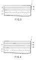
- FIGS. 3 and 4 are cross-sectional views schematically showing other examples of structure that can be employed in the exhaust gas-purifying catalyst shown in FIG. 1 .
- the exhaust gas-purifying catalyst 1 shown in FIG. 3 has the same structure as that of the exhaust gas-purifying catalyst 1 shown in FIG. 2 except that the first catalytic layer 4a is interposed between the hydrocarbon-adsorbing layer 3 and the second catalytic layer 4b. Like this, the stacking order of the first catalytic layer 4a and the second catalytic layer 4b can be freely determined.
- the exhaust gas-purifying catalyst 1 shown in FIG. 4 has the same structure as that of the exhaust gas-purifying catalyst 1 shown in FIG. 2 except that the catalytic layer 4 is constituted by two first catalytic layers 4a and the second catalytic layer 4b interposed therebetween. Like this, the catalytic layer 4 may includes a plurality of first catalytic layers 4a. Similarly, the catalytic layer 4 may includes a plurality of second catalytic layers 4b.
- the exhaust gas-purifying catalyst 1 shown in FIG. 2 was manufactured by the following method.
- slurry S1 100g of zeolite and 100 mL of deionized water are mixed together to prepare slurry.
- slurry S1 100g of zeolite and 100 mL of deionized water are mixed together.
- slurry S1 100g of zeolite and 100 mL of deionized water are mixed together.
- slurry S1 100g of zeolite and 100 mL of deionized water
- a monolith honeycomb substrate 2 made of cordierite was coated with whole of the slurry S1.
- the monolith honeycomb substrate used was the one that has a volumetric capacity of 1.0L and was provided with 900 cells per square inch.
- the monolith honeycomb substrate 2 was dried at 250°C for 1 hour, and subsequently, fired at 500°C for 1 hour.
- the hydrocarbon-adsorbing layer 3 was formed on the monolith honeycomb substrate 2.
- slurry S2 10g of alumina powder, 10g of cerium-zirconium composite oxide powder, aqueous palladium nitrate containing 0.25g of palladium, and aqueous rhodium nitrate containing 0.25g of rhodium were mixed together to prepare slurry.
- the slurry is referred to as slurry S2.
- the above monolith honeycomb substrate 2 was coated with whole of the slurry S2.
- the monolith honeycomb substrate 2 was dried at 250°C for 1 hour, and subsequently, fired at 500°C for 1 hour.
- the second catalytic layer 4b was formed on the monolith honeycomb substrate 2.
- slurry S3 40g of alumina powder, 40g of cerium-zirconium composite oxide powder, aqueous palladium nitrate containing 0.25g of palladium, and aqueous rhodium nitrate containing 0.25g of rhodium were mixed together to prepare slurry.
- the slurry is referred to as slurry S3.
- the above monolith honeycomb substrate 2 was coated with whole of the slurry S3.
- the monolith honeycomb substrate 2 was dried at 250°C for 1 hour, and subsequently, fired at 500°C for 1 hour.
- the first catalytic layer 4a was formed on the second catalytic layer 4b.
- the exhaust gas-purifying catalyst 1 shown in FIG. 2 was thus completed.
- the exhaust gas-purifying catalyst 1 is referred to as catalyst A.
- the exhaust gas-purifying catalyst 1 shown in FIG. 3 was manufactured by the following method.
- the exhaust gas-purifying catalyst 1 shown in FIG. 3 was manufactured by the same method as that described for the catalyst A except that the slurry S3 was used instead of the slurry S2 and the slurry S2 was used instead of the slurry S3.
- the exhaust gas-purifying catalyst 1 is referred to as catalyst B.
- the exhaust gas-purifying catalyst 1 shown in FIG. 4 was manufactured by the following method.
- the hydrocarbon-adsorbing layer 3 was formed on the monolith honeycomb substrate 2 by the same method as that described for the catalyst A.
- the above monolith honeycomb substrate 2 was coated with half the slurry S3.
- the monolith honeycomb substrate 2 was dried at 250°C for 1 hour, and subsequently, fired at 500°C for 1 hour.
- the first catalytic layer 4a was formed on the hydrocarbon-adsorbing layer 3.
- the above monolith honeycomb substrate 2 was coated with whole the slurry S2.
- the monolith honeycomb substrate 2 was dried at 250°C for 1 hour, and subsequently, fired at 500°C for 1 hour.
- the second catalytic layer 4b was formed on the first catalytic layer 4a.
- the above monolith honeycomb substrate 2 was coated with half the slurry S3.
- the monolith honeycomb substrate 2 was dried at 250°C for 1 hour, and subsequently, fired at 500°C for 1 hour.
- the first catalytic layer 4a was formed on the second catalytic layer 4b.
- the exhaust gas-purifying catalyst 1 shown in FIG. 4 was thus completed.
- the exhaust gas-purifying catalyst 1 is referred to as catalyst C.
- the exhaust gas-purifying catalyst 1 shown in FIG. 2 was manufactured by the following method.
- the hydrocarbon-adsorbing layer 3 was formed on the monolith honeycomb substrate 2 by the same method as that described for the catalyst A.
- slurry S4 2.5g of alumina powder, 2.5g of cerium-zirconium composite oxide powder, aqueous palladium nitrate containing 0.25g of palladium, and aqueous rhodium nitrate containing 0.25g of rhodium were mixed together to prepare slurry.
- the slurry is referred to as slurry S4.
- the above monolith honeycomb substrate 2 was coated with whole the slurry S4.
- the monolith honeycomb substrate 2 was dried at 250°C for 1 hour, and subsequently, fired at 500°C for 1 hour.
- the second catalytic layer 4b was formed on the hydrocarbon-adsorbing layer 3.
- slurry S5 47.5g of alumina powder, 47.5g of cerium-zirconium composite oxide powder, aqueous palladium nitrate containing 0.25g of palladium, and aqueous rhodium nitrate containing 0.25g of rhodium were mixed together to prepare slurry.
- the slurry is referred to as slurry S5.
- the above monolith honeycomb substrate 2 was coated with whole the slurry S5.
- the monolith honeycomb substrate 2 was dried at 250°C for 1 hour, and subsequently, fired at 500°C for 1 hour.
- the first catalytic layer 4a was formed on the second catalytic layer 4b.
- the exhaust gas-purifying catalyst 1 shown in FIG. 2 was thus completed.
- the exhaust gas-purifying catalyst 1 is referred to as catalyst D.
- the exhaust gas-purifying catalyst 1 shown in FIG. 2 was manufactured by the following method.
- the hydrocarbon-adsorbing layer 3 was formed on the monolith honeycomb substrate 2 by the same method as that described for the catalyst A.
- slurry S6 20g of alumina powder, 20g of cerium-zirconium composite oxide powder, aqueous palladium nitrate containing 0.25g of palladium, and aqueous rhodium nitrate containing 0.25g of rhodium were mixed together to prepare slurry.
- the slurry is referred to as slurry S6.
- the above monolith honeycomb substrate 2 was coated with whole the slurry S6.
- the monolith honeycomb substrate 2 was dried at 250°C for 1 hour, and subsequently, fired at 500°C for 1 hour.
- the second catalytic layer 4b was formed on the hydrocarbon-adsorbing layer 3.
- slurry S7 60g of alumina powder, 60g of cerium-zirconium composite oxide powder, aqueous palladium nitrate containing 0.25g of palladium, and aqueous rhodium nitrate containing 0.25g of rhodium were mixed together to prepare slurry.
- the slurry is referred to as slurry S7.
- the above monolith honeycomb substrate 2 was coated with whole the slurry S7.
- the monolith honeycomb substrate 2 was dried at 250°C for 1 hour, and subsequently, fired at 500°C for 1 hour.
- the first catalytic layer 4a was formed on the second catalytic layer 4b.
- the exhaust gas-purifying catalyst 1 shown in FIG. 2 was thus completed.
- the exhaust gas-purifying catalyst 1 is referred to as catalyst E.
- the exhaust gas-purifying catalyst 1 shown in FIG. 2 was manufactured by the following method.
- the hydrocarbon-adsorbing layer 3 was formed on the monolith honeycomb substrate 2 by the same method as that described for the catalyst A.
- slurry S8 10g of alumina powder, 10g of cerium-zirconium composite oxide powder, aqueous palladium nitrate containing 0.15g of palladium, and aqueous rhodium nitrate containing 0.15g of rhodium were mixed together to prepare slurry.
- the slurry is referred to as slurry S8.
- the above monolith honeycomb substrate 2 was coated with whole the slurry S8.
- the monolith honeycomb substrate 2 was dried at 250°C for 1 hour, and subsequently, fired at 500°C for 1 hour.
- the second catalytic layer 4b was formed on the hydrocarbon-adsorbing layer 3.
- slurry S9 aqueous palladium nitrate containing 0.35g of palladium, and aqueous rhodium nitrate containing 0.35g of rhodium
- the above monolith honeycomb substrate 2 was coated with whole the slurry S9.
- the monolith honeycomb substrate 2 was dried at 250°C for 1 hour, and subsequently, fired at 500°C for 1 hour.
- the first catalytic layer 4a was formed on the second catalytic layer 4b.
- the exhaust gas-purifying catalyst 1 shown in FIG. 2 was thus completed.
- the exhaust gas-purifying catalyst 1 is referred to as catalyst F.
- the exhaust gas-purifying catalyst 1 shown in FIG. 2 was manufactured by the following method.
- the hydrocarbon-adsorbing layer 3 was formed on the monolith honeycomb substrate 2 by the same method as that described for the catalyst A.
- slurry S10 10g of alumina powder, 10g of cerium-zirconium composite oxide powder, aqueous palladium nitrate containing 0.475g of palladium, and aqueous rhodium nitrate containing 0.475g of rhodium were mixed together to prepare slurry.
- the slurry is referred to as slurry S10.
- the above monolith honeycomb substrate 2 was coated with whole the slurry S10.
- the monolith honeycomb substrate 2 was dried at 250°C for 1 hour, and subsequently, fired at 500°C for 1 hour.
- the second catalytic layer 4b was formed on the hydrocarbon-adsorbing layer 3.
- slurry S11 40g of alumina powder, 40g of cerium-zirconium composite oxide powder, aqueous palladium nitrate containing 0.025g of palladium, and aqueous rhodium nitrate containing 0.025g of rhodium were mixed together to prepare slurry.
- the slurry is referred to as slurry S11.
- the above monolith honeycomb substrate 2 was coated with whole the slurry S11.
- the monolith honeycomb substrate 2 was dried at 250°C for 1 hour, and subsequently, fired at 500°C for 1 hour.
- the first catalytic layer 4a was formed on the second catalytic layer 4b.
- the exhaust gas-purifying catalyst 1 shown in FIG. 2 was thus completed.
- the exhaust gas-purifying catalyst 1 is referred to as catalyst G.
- an exhaust gas-purifying catalyst was manufactured by the following method.
- a hydrocarbon-adsorbing layer was formed on a monolith honeycomb substrate by the same method as that described for the catalyst A.
- slurry S12 50g of alumina powder, 50g of cerium-zirconium composite oxide powder, aqueous palladium nitrate containing 0.5g of palladium, and aqueous rhodium nitrate containing 0.5g of rhodium were mixed together to prepare slurry.
- the slurry is referred to as slurry S12.
- the above monolith honeycomb substrate was coated with whole the slurry S10.
- the monolith honeycomb substrate was dried at 250°C for 1 hour, and subsequently, fired at 500°C for 1 hour.
- a catalytic layer was formed on the hydrocarbon-adsorbing layer.
- catalyst H the exhaust gas-purifying catalyst
- each of the catalysts A to H was mounted on an automobile having an engine with a piston displacement of 2.0L. Then, each automobile was driven to 80,000 km of endurance travel distance. Thereafter, emission per test was determined for each of total hydrocarbon (THC), CO and NO X by 11-mode method. Note that the emission of THC is a value in gram obtained by converting a value represented in volumetric ratio based on equivalent carbon number.
- Table 1 Catalyst THC (g/test) CO (g/test) NO X (g/test) A 0.61 5.20 0.50 B 0.62 5.18 0.51 C 0.59 5.22 0.49 D 0.57 5.25 0.53 E 0.63 5.19 0.49 F 0.60 5.21 0.51 G 0.61 5.19 0.52 H 0.85 5.30 0.55
Landscapes
- Chemical & Material Sciences (AREA)
- Engineering & Computer Science (AREA)
- Chemical Kinetics & Catalysis (AREA)
- Organic Chemistry (AREA)
- Materials Engineering (AREA)
- Combustion & Propulsion (AREA)
- Health & Medical Sciences (AREA)
- Oil, Petroleum & Natural Gas (AREA)
- General Chemical & Material Sciences (AREA)
- Analytical Chemistry (AREA)
- Environmental & Geological Engineering (AREA)
- Biomedical Technology (AREA)
- Crystallography & Structural Chemistry (AREA)
- Toxicology (AREA)
- Mechanical Engineering (AREA)
- General Engineering & Computer Science (AREA)
- Catalysts (AREA)
- Exhaust Gas Treatment By Means Of Catalyst (AREA)
- Exhaust Gas After Treatment (AREA)
Abstract
Description
- The present invention relates to an exhaust gas-purifying catalyst, in particular, to an exhaust gas-purifying catalyst including hydrocarbon-adsorbing material.
- Until today, as an exhaust-gas purifying catalyst for treating an exhaust gas from an automobile, etc., used widely is a three-way catalyst in which a refractory carrier made of an inorganic oxide such as alumina supports a precious metal. In the three-way catalyst, the precious metal plays the role in promoting the reduction of nitrogen oxides (NOX) and the oxidations of carbon monoxide (CO) and hydrocarbons (HC). Further, the refractory carrier plays the roles in increasing the specific surface area of the precious metal and suppressing the sintering of the precious metal by dissipating heat generated by the reactions.
- In some cases, a three-way catalyst is used in combination with a hydrocarbon-adsorbing material such as zeolite as described in
JP-A 11-210451 - However, the present inventors have found in the course of achieving the present invention that an automotive vehicle having such a three-way catalyst is susceptible to improvement in terms of HC emission.
- An object of the present invention is to make it possible to decrease HC emission.
- According to an aspect of the present invention, there is provided an exhaust gas-purifying catalyst comprising a substrate, a hydrocarbon-adsorbing layer covering the substrate, and a catalytic layer covering the hydrocarbon-adsorbing layer, wherein the catalytic layer includes a layered structure of a first catalytic layer including a precious metal and a carrier supporting it, and a second catalytic layer including the same precious metal as the above precious metal and a carrier supporting it, a concentration of the precious metal in the second catalytic layer being higher than that in the first catalytic layer.
-
-
FIG. 1 is a perspective view schematically showing an exhaust gas-purifying catalyst according to an embodiment of the present invention; -
FIG. 2 is a cross-sectional view schematically showing an example of structure that can be employed in the exhaust gas-purifying catalyst shown inFIG. 1 ; -
FIG. 3 is a cross-sectional view schematically showing another example of structure that can be employed in the exhaust gas-purifying catalyst shown inFIG. 1 ; and -
FIG. 4 is a cross-sectional view schematically showing another example of structure that can be employed in the exhaust gas-purifying catalyst shown inFIG. 1 . - An embodiment of the present invention will be described below.
-
FIG. 1 is a perspective view schematically showing an exhaust gas-purifying catalyst according to an embodiment of the present invention.FIG. 2 is a cross-sectional view schematically showing an example of structure that can be employed in the exhaust gas-purifying catalyst shown inFIG. 1 . - The exhaust gas-purifying
catalyst 1 shown inFIGS. 1 and 2 is a monolith catalyst. The exhaust gas-purifyingcatalyst 1 includes asubstrate 2 such as monolith honeycomb substrate. Typically, thesubstrate 2 is made of ceramics such as cordierite. - On the wall of the
support substrate 2, a hydrocarbon-adsorbinglayer 3 is formed. The hydrocarbon-adsorbinglayer 3 includes a hydrocarbon-adsorbing material such as zeolite. The hydrocarbon-adsorbinglayer 3 may further include other materials in addition to the hydrocarbon-adsorbing material. For example, it may further include the refractory carrier and/or oxygen storage material to be described later. - On the hydrocarbon-adsorbing
layer 3, acatalytic layer 4 is formed. Thecatalytic layer 3 includes a layered structure of a firstcatalytic layer 4a and a secondcatalytic layer 4b. In the example shown inFIG. 2 , thecatalytic layer 4 is constituted by the firstcatalytic layer 4a and the secondcatalytic layer 4b, and the secondcatalytic layer 4b is interposed between the hydrogen-adsorbinglayer 3 and the firstcatalytic layer 4a. - The first
catalytic layer 4a includes a carrier and a precious metal supported thereby. - The carrier included in the first
catalytic layer 4a is refractory carrier and/or oxygen storage material. - The refractory carrier is excellent in heat stability as compared with the oxygen storage material. As the material of the refractory carrier, alumina, zirconia or titania can be used, for example.
- The oxygen storage material is, for example, ceria, composite oxide and/or solid solution of ceria and another metal oxide, or a mixture thereof. As the composite oxide and/or solid solution, composite oxide and/or solid solution of ceria and zirconia can be used, for example.
- The precious metal included in the first
catalytic layer 4a is, for example, an element of platinum group such as platinum, rhodium and palladium. Here, as an example, it is supposed that the firstcatalytic layer 4a includes at least rhodium and palladium. The concentration of palladium in the firstcatalytic layer 4a falls within a range of 0.2% by mass to 10% by mass, for example. The concentration of rhodium in the firstcatalytic layer 4a falls within a range of 0.2% by mass to 10% by mass, for example. - The thickness of the first
catalytic layer 4a is set within a range of 10 µm to 100 µm, for example. - The second
catalytic layer 4b includes a carrier and a precious metal supported thereby. - The carrier included in the second
catalytic layer 4b is refractory carrier and/or oxygen storage material. As the refractory carrier and/or oxygen storage material, the materials mentioned for the firstcatalytic layer 4a can be used, for example. The carrier included in the firstcatalytic layer 4a and carrier included in the secondcatalytic layer 4b may be the same or different from each other. - The precious metal included in the second
catalytic layer 4b is, for example, an element of platinum group such as platinum, rhodium and palladium. Here, as an example, it is supposed that the secondcatalytic layer 4b includes at least palladium. The concentration of palladium in the secondcatalytic layer 4b falls within a range of 0.2% by mass to 30% by mass, for example. - The second
catalytic layer 4b includes the same precious material as that included in the firstcatalytic layer 4a. The concentration of the precious metal in the secondcatalytic layer 4b is higher than that in the firstcatalytic layer 4a. In this example, the firstcatalytic layer 4a and the secondcatalytic layer 4b include palladium. The concentration of palladium in the secondcatalytic layer 4b is higher than that in the firstcatalytic layer 4a. For example, a ratio of the concentration of the palladium in the secondcatalytic layer 4b with respect to the concentration of the palladium in the firstcatalytic layer 4a falls within a range of 1 to 50, for example. - Note that the concentration of the precious metal other than palladium may be higher in either of the first
catalytic layer 4a and the secondcatalytic layer 4b. Alternatively, they may have equal concentrations of the precious metal other than palladium. - The mass ratio of palladium included in the second
catalytic layer 4b with respect to palladium included in thecatalytic layer 4 is set, for example, within a range of 30% by mass to 95% by mass. - The thickness of the second
catalytic layer 4b is set, for example, within a range of 5 µm to 50 µm. - The ratio of the thickness of the second
catalytic layer 4b with respect to the thickness of thecatalytic layer 4 is set, for example, within a range of 5% to 40%. - The
catalytic layer 4 can further include an oxide of alkaline-earth metal such as barium; an oxide of rare-earth element such as lanthanum, neodymium, praseodymium and yttrium; or a mixture thereof. The oxides together with other oxides such as ceria may form composite oxide and/or solid solution. The oxides may be included in either or both of the firstcatalytic layer 4a and the secondcatalytic layer 4b. - A layer including the above-described refractory carrier and the oxygen storage material may be interposed between the hydrocarbon-adsorbing
layer 3 and thecatalytic layer 4. - In the exhaust gas-purifying
catalyst 1, the composition of the firstcatalytic layer 4a is normally determined such that the reduction of NOX contained in the exhaust gas and the oxidations of CO and HC contained in the exhaust gas are optimized. However, such a composition is not optimum for oxidation of HC desorbed from the hydrocarbon-adsorbinglayer 3. To be more specific, the concentration of palladium in the firstcatalytic layer 4a is too low for oxidation of HC desorbed from the hydrocarbon-adsorbinglayer 3. Thus, in the case where the secondcatalytic layer 4b is omitted from the exhaust gas-purifying catalyst 1, most of HC desorbed from the hydrocarbon-adsorbinglayer 3 is released into the atmosphere without being oxidized. - As described above, in the exhaust gas-
purifying catalyst 1, the layered structure of the firstcatalytic layer 4a, which includes palladium at a lower concentration and further includes rhodium, and the secondcatalytic layer 4b, which includes palladium at a higher concentration, is disposed on the hydrocarbon-adsorbinglayer 3. The secondcatalytic layer 4b can oxidize HC desorbed from the hydrocarbon-adsorbinglayer 3 at a higher efficiency as compared with the firstcatalytic layer 4a. Therefore, when the exhaust gas-purifying catalyst 1 is used, HC emission can be decreased. - Various modifications can be made to the exhaust gas-
purifying catalyst 1. -
FIGS. 3 and 4 are cross-sectional views schematically showing other examples of structure that can be employed in the exhaust gas-purifying catalyst shown inFIG. 1 . - The exhaust gas-
purifying catalyst 1 shown inFIG. 3 has the same structure as that of the exhaust gas-purifying catalyst 1 shown inFIG. 2 except that the firstcatalytic layer 4a is interposed between the hydrocarbon-adsorbinglayer 3 and the secondcatalytic layer 4b. Like this, the stacking order of the firstcatalytic layer 4a and the secondcatalytic layer 4b can be freely determined. - The exhaust gas-
purifying catalyst 1 shown inFIG. 4 has the same structure as that of the exhaust gas-purifying catalyst 1 shown inFIG. 2 except that thecatalytic layer 4 is constituted by two firstcatalytic layers 4a and the secondcatalytic layer 4b interposed therebetween. Like this, thecatalytic layer 4 may includes a plurality of firstcatalytic layers 4a. Similarly, thecatalytic layer 4 may includes a plurality of secondcatalytic layers 4b. - Examples of the present invention will be described below.
- In this example, the exhaust gas-
purifying catalyst 1 shown inFIG. 2 was manufactured by the following method. - 100g of zeolite and 100 mL of deionized water are mixed together to prepare slurry. Hereinafter, the slurry is referred to as slurry S1.
- Then, a
monolith honeycomb substrate 2 made of cordierite was coated with whole of the slurry S1. Here, as the monolith honeycomb substrate, used was the one that has a volumetric capacity of 1.0L and was provided with 900 cells per square inch. Themonolith honeycomb substrate 2 was dried at 250°C for 1 hour, and subsequently, fired at 500°C for 1 hour. Thus, the hydrocarbon-adsorbinglayer 3 was formed on themonolith honeycomb substrate 2. - Next, 10g of alumina powder, 10g of cerium-zirconium composite oxide powder, aqueous palladium nitrate containing 0.25g of palladium, and aqueous rhodium nitrate containing 0.25g of rhodium were mixed together to prepare slurry. Hereinafter, the slurry is referred to as slurry S2.
- Then, the above
monolith honeycomb substrate 2 was coated with whole of the slurry S2. Themonolith honeycomb substrate 2 was dried at 250°C for 1 hour, and subsequently, fired at 500°C for 1 hour. Thus, the secondcatalytic layer 4b was formed on themonolith honeycomb substrate 2. - Thereafter, 40g of alumina powder, 40g of cerium-zirconium composite oxide powder, aqueous palladium nitrate containing 0.25g of palladium, and aqueous rhodium nitrate containing 0.25g of rhodium were mixed together to prepare slurry. Hereinafter, the slurry is referred to as slurry S3.
- Then, the above
monolith honeycomb substrate 2 was coated with whole of the slurry S3. Themonolith honeycomb substrate 2 was dried at 250°C for 1 hour, and subsequently, fired at 500°C for 1 hour. Thus, the firstcatalytic layer 4a was formed on the secondcatalytic layer 4b. - The exhaust gas-
purifying catalyst 1 shown inFIG. 2 was thus completed. Hereinafter, the exhaust gas-purifying catalyst 1 is referred to as catalyst A. - In this example, the exhaust gas-
purifying catalyst 1 shown inFIG. 3 was manufactured by the following method. - That is, in this example, the exhaust gas-
purifying catalyst 1 shown inFIG. 3 was manufactured by the same method as that described for the catalyst A except that the slurry S3 was used instead of the slurry S2 and the slurry S2 was used instead of the slurry S3. Hereinafter, the exhaust gas-purifying catalyst 1 is referred to as catalyst B. - In this example, the exhaust gas-
purifying catalyst 1 shown inFIG. 4 was manufactured by the following method. - The hydrocarbon-adsorbing
layer 3 was formed on themonolith honeycomb substrate 2 by the same method as that described for the catalyst A. - Then, the above
monolith honeycomb substrate 2 was coated with half the slurry S3. Themonolith honeycomb substrate 2 was dried at 250°C for 1 hour, and subsequently, fired at 500°C for 1 hour. Thus, the firstcatalytic layer 4a was formed on the hydrocarbon-adsorbinglayer 3. - Thereafter, the above
monolith honeycomb substrate 2 was coated with whole the slurry S2. Themonolith honeycomb substrate 2 was dried at 250°C for 1 hour, and subsequently, fired at 500°C for 1 hour. Thus, the secondcatalytic layer 4b was formed on the firstcatalytic layer 4a. - Further, the above
monolith honeycomb substrate 2 was coated with half the slurry S3. Themonolith honeycomb substrate 2 was dried at 250°C for 1 hour, and subsequently, fired at 500°C for 1 hour. Thus, the firstcatalytic layer 4a was formed on the secondcatalytic layer 4b. - The exhaust gas-
purifying catalyst 1 shown inFIG. 4 was thus completed. Hereinafter, the exhaust gas-purifying catalyst 1 is referred to as catalyst C. - In this example, the exhaust gas-
purifying catalyst 1 shown inFIG. 2 was manufactured by the following method. - The hydrocarbon-adsorbing
layer 3 was formed on themonolith honeycomb substrate 2 by the same method as that described for the catalyst A. - Next, 2.5g of alumina powder, 2.5g of cerium-zirconium composite oxide powder, aqueous palladium nitrate containing 0.25g of palladium, and aqueous rhodium nitrate containing 0.25g of rhodium were mixed together to prepare slurry. Hereinafter, the slurry is referred to as slurry S4.
- Then, the above
monolith honeycomb substrate 2 was coated with whole the slurry S4. Themonolith honeycomb substrate 2 was dried at 250°C for 1 hour, and subsequently, fired at 500°C for 1 hour. Thus, the secondcatalytic layer 4b was formed on the hydrocarbon-adsorbinglayer 3. - Thereafter, 47.5g of alumina powder, 47.5g of cerium-zirconium composite oxide powder, aqueous palladium nitrate containing 0.25g of palladium, and aqueous rhodium nitrate containing 0.25g of rhodium were mixed together to prepare slurry. Hereinafter, the slurry is referred to as slurry S5.
- Then, the above
monolith honeycomb substrate 2 was coated with whole the slurry S5. Themonolith honeycomb substrate 2 was dried at 250°C for 1 hour, and subsequently, fired at 500°C for 1 hour. Thus, the firstcatalytic layer 4a was formed on the secondcatalytic layer 4b. - The exhaust gas-
purifying catalyst 1 shown inFIG. 2 was thus completed. Hereinafter, the exhaust gas-purifying catalyst 1 is referred to as catalyst D. - In this example, the exhaust gas-
purifying catalyst 1 shown inFIG. 2 was manufactured by the following method. - The hydrocarbon-adsorbing
layer 3 was formed on themonolith honeycomb substrate 2 by the same method as that described for the catalyst A. - Next, 20g of alumina powder, 20g of cerium-zirconium composite oxide powder, aqueous palladium nitrate containing 0.25g of palladium, and aqueous rhodium nitrate containing 0.25g of rhodium were mixed together to prepare slurry. Hereinafter, the slurry is referred to as slurry S6.
- Then, the above
monolith honeycomb substrate 2 was coated with whole the slurry S6. Themonolith honeycomb substrate 2 was dried at 250°C for 1 hour, and subsequently, fired at 500°C for 1 hour. Thus, the secondcatalytic layer 4b was formed on the hydrocarbon-adsorbinglayer 3. - Thereafter, 60g of alumina powder, 60g of cerium-zirconium composite oxide powder, aqueous palladium nitrate containing 0.25g of palladium, and aqueous rhodium nitrate containing 0.25g of rhodium were mixed together to prepare slurry. Hereinafter, the slurry is referred to as slurry S7.
- Then, the above
monolith honeycomb substrate 2 was coated with whole the slurry S7. Themonolith honeycomb substrate 2 was dried at 250°C for 1 hour, and subsequently, fired at 500°C for 1 hour. Thus, the firstcatalytic layer 4a was formed on the secondcatalytic layer 4b. - The exhaust gas-
purifying catalyst 1 shown inFIG. 2 was thus completed. Hereinafter, the exhaust gas-purifying catalyst 1 is referred to as catalyst E. - In this example, the exhaust gas-
purifying catalyst 1 shown inFIG. 2 was manufactured by the following method. - The hydrocarbon-adsorbing
layer 3 was formed on themonolith honeycomb substrate 2 by the same method as that described for the catalyst A. - Next, 10g of alumina powder, 10g of cerium-zirconium composite oxide powder, aqueous palladium nitrate containing 0.15g of palladium, and aqueous rhodium nitrate containing 0.15g of rhodium were mixed together to prepare slurry. Hereinafter, the slurry is referred to as slurry S8.
- Then, the above
monolith honeycomb substrate 2 was coated with whole the slurry S8. Themonolith honeycomb substrate 2 was dried at 250°C for 1 hour, and subsequently, fired at 500°C for 1 hour. Thus, the secondcatalytic layer 4b was formed on the hydrocarbon-adsorbinglayer 3. - Thereafter, 40g of alumina powder, 40g of cerium-zirconium composite oxide powder, aqueous palladium nitrate containing 0.35g of palladium, and aqueous rhodium nitrate containing 0.35g of rhodium were mixed together to prepare slurry. Hereinafter, the slurry is referred to as slurry S9.
- Then, the above
monolith honeycomb substrate 2 was coated with whole the slurry S9. Themonolith honeycomb substrate 2 was dried at 250°C for 1 hour, and subsequently, fired at 500°C for 1 hour. Thus, the firstcatalytic layer 4a was formed on the secondcatalytic layer 4b. - The exhaust gas-
purifying catalyst 1 shown inFIG. 2 was thus completed. Hereinafter, the exhaust gas-purifying catalyst 1 is referred to as catalyst F. - In this example, the exhaust gas-
purifying catalyst 1 shown inFIG. 2 was manufactured by the following method. - The hydrocarbon-adsorbing
layer 3 was formed on themonolith honeycomb substrate 2 by the same method as that described for the catalyst A. - Next, 10g of alumina powder, 10g of cerium-zirconium composite oxide powder, aqueous palladium nitrate containing 0.475g of palladium, and aqueous rhodium nitrate containing 0.475g of rhodium were mixed together to prepare slurry. Hereinafter, the slurry is referred to as slurry S10.
- Then, the above
monolith honeycomb substrate 2 was coated with whole the slurry S10. Themonolith honeycomb substrate 2 was dried at 250°C for 1 hour, and subsequently, fired at 500°C for 1 hour. Thus, the secondcatalytic layer 4b was formed on the hydrocarbon-adsorbinglayer 3. - Thereafter, 40g of alumina powder, 40g of cerium-zirconium composite oxide powder, aqueous palladium nitrate containing 0.025g of palladium, and aqueous rhodium nitrate containing 0.025g of rhodium were mixed together to prepare slurry. Hereinafter, the slurry is referred to as slurry S11.
- Then, the above
monolith honeycomb substrate 2 was coated with whole the slurry S11. Themonolith honeycomb substrate 2 was dried at 250°C for 1 hour, and subsequently, fired at 500°C for 1 hour. Thus, the firstcatalytic layer 4a was formed on the secondcatalytic layer 4b. - The exhaust gas-
purifying catalyst 1 shown inFIG. 2 was thus completed. Hereinafter, the exhaust gas-purifying catalyst 1 is referred to as catalyst G. - In this example, an exhaust gas-purifying catalyst was manufactured by the following method.
- A hydrocarbon-adsorbing layer was formed on a monolith honeycomb substrate by the same method as that described for the catalyst A.
- Next, 50g of alumina powder, 50g of cerium-zirconium composite oxide powder, aqueous palladium nitrate containing 0.5g of palladium, and aqueous rhodium nitrate containing 0.5g of rhodium were mixed together to prepare slurry. Hereinafter, the slurry is referred to as slurry S12.
- Then, the above monolith honeycomb substrate was coated with whole the slurry S10. The monolith honeycomb substrate was dried at 250°C for 1 hour, and subsequently, fired at 500°C for 1 hour. Thus, a catalytic layer was formed on the hydrocarbon-adsorbing layer.
- An exhaust gas-purifying catalyst was thus completed. Hereinafter, the exhaust gas-purifying catalyst is referred to as catalyst H.
- Each of the catalysts A to H was mounted on an automobile having an engine with a piston displacement of 2.0L. Then, each automobile was driven to 80,000 km of endurance travel distance. Thereafter, emission per test was determined for each of total hydrocarbon (THC), CO and NOX by 11-mode method. Note that the emission of THC is a value in gram obtained by converting a value represented in volumetric ratio based on equivalent carbon number.
table 1 Catalyst THC (g/test) CO (g/test) NOX (g/test) A 0.61 5.20 0.50 B 0.62 5.18 0.51 C 0.59 5.22 0.49 D 0.57 5.25 0.53 E 0.63 5.19 0.49 F 0.60 5.21 0.51 G 0.61 5.19 0.52 H 0.85 5.30 0.55 - As shown in the above table, in the case where the catalysts A to G were used, each emission of THC, CO and NOX was low as compared with the case where the catalyst H was used. Particularly, in the case where the catalysts A to G were used, THC emission was significantly decreased as compared with the case where the catalyst H was used.
- Additional advantages and modifications will readily occur to those skilled in the art. Therefore, the invention in its broader aspects is not limited to the specific details and representative embodiments shown and described herein. Accordingly, various modifications may be made without departing from the spirit or scope of the general invention concept as defined by the appended claims and their equivalents.
Claims (8)
- An exhaust gas-purifying catalyst comprising:a substrate;a hydrocarbon-adsorbing layer covering the substrate; anda catalytic layer covering the hydrocarbon-adsorbing layer, wherein the catalytic layer includes a layered structure of a first catalytic layer including a precious metal and a carrier supporting it, and a second catalytic layer including the same precious metal as the above precious metal and a carrier supporting it, a concentration of the precious metal in the second catalytic layer being higher than that in the first catalytic layer.
- The exhaust gas-purifying catalyst according to claim 1, wherein each of the first and second catalytic layers includes palladium, a concentration of palladium in the second catalytic layer being higher than that in the first catalytic layer.
- The exhaust gas-purifying catalyst according to claim 2, wherein each of the first and second catalytic layers includes rhodium, a concentration of rhodium in the second catalytic layer being higher than that in the first catalytic layer.
- The exhaust gas-purifying catalyst according to claim 1, wherein each of the first and second catalytic layers includes rhodium, a concentration of rhodium in the second catalytic layer being higher than that in the first catalytic layer.
- The exhaust gas-purifying catalyst according to claim 1, wherein each of the first and second catalytic layers further includes an oxygen storage material.
- The exhaust gas-purifying catalyst according to claim 1, wherein the second catalytic layer is interposed between the substrate and the first catalytic layer.
- The exhaust gas-purifying catalyst according to claim 1, wherein the first catalytic layer is interposed between the substrate and the second catalytic layer.
- The exhaust gas-purifying catalyst according to claim 1, wherein catalytic layer includes a plurality of the first catalytic layers, and the second catalytic layer is interposed between two of the first catalytic layers.
Applications Claiming Priority (2)
| Application Number | Priority Date | Filing Date | Title |
|---|---|---|---|
| JP2006294913A JP5173180B2 (en) | 2006-10-30 | 2006-10-30 | Exhaust gas purification catalyst |
| PCT/JP2007/070048 WO2008053690A1 (en) | 2006-10-30 | 2007-10-15 | Exhaust gas purifying catalyst |
Publications (3)
| Publication Number | Publication Date |
|---|---|
| EP2078562A1 true EP2078562A1 (en) | 2009-07-15 |
| EP2078562A4 EP2078562A4 (en) | 2014-04-30 |
| EP2078562B1 EP2078562B1 (en) | 2019-09-18 |
Family
ID=39344035
Family Applications (1)
| Application Number | Title | Priority Date | Filing Date |
|---|---|---|---|
| EP07829782.7A Active EP2078562B1 (en) | 2006-10-30 | 2007-10-15 | Exhaust gas purifying catalyst |
Country Status (5)
| Country | Link |
|---|---|
| US (1) | US8133837B2 (en) |
| EP (1) | EP2078562B1 (en) |
| JP (1) | JP5173180B2 (en) |
| CN (1) | CN101522304A (en) |
| WO (1) | WO2008053690A1 (en) |
Cited By (1)
| Publication number | Priority date | Publication date | Assignee | Title |
|---|---|---|---|---|
| CN105804839A (en) * | 2015-01-15 | 2016-07-27 | 埃贝斯佩歇排气技术有限责任两合公司 | Support ring for an exhaust gas duct system |
Families Citing this family (10)
| Publication number | Priority date | Publication date | Assignee | Title |
|---|---|---|---|---|
| JP4838258B2 (en) * | 2005-10-05 | 2011-12-14 | 株式会社キャタラー | Exhaust gas purification catalyst |
| JP5270075B2 (en) * | 2006-07-04 | 2013-08-21 | 株式会社キャタラー | Exhaust gas purification catalyst |
| US7754171B2 (en) | 2007-02-02 | 2010-07-13 | Basf Corporation | Multilayered catalyst compositions |
| US20090175773A1 (en) * | 2008-01-08 | 2009-07-09 | Chen Shau-Lin F | Multilayered Catalyst Compositions |
| US8865082B2 (en) | 2009-10-05 | 2014-10-21 | GM Global Technology Operations LLC | Method and system for monitoring a hydrocarbon adsorber |
| US20120204547A1 (en) * | 2009-10-21 | 2012-08-16 | Honda Motor Co., Ltd. | Exhaust gas purification catalyst and exhaust gas purification apparatus using same |
| US8950174B2 (en) | 2010-09-02 | 2015-02-10 | Basf Se | Catalysts for gasoline lean burn engines with improved NH3-formation activity |
| BR112013005099B1 (en) * | 2010-09-02 | 2019-04-30 | Basf Se | CATALYST, METHOD FOR PRODUCING A CATALYST, PROCESS FOR TREATING A GAS CURRENT, AND USING THE CATALYST |
| CN115155668B (en) * | 2014-10-16 | 2025-10-24 | 株式会社科特拉 | Catalysts for exhaust gas purification |
| JP7288331B2 (en) * | 2019-03-29 | 2023-06-07 | 株式会社キャタラー | Exhaust gas purification catalyst device |
Family Cites Families (59)
| Publication number | Priority date | Publication date | Assignee | Title |
|---|---|---|---|---|
| JPS6017239A (en) | 1983-07-07 | 1985-01-29 | Nissan Motor Co Ltd | Control device of combustion in internal-combustion engine |
| JPS6017239U (en) * | 1983-07-11 | 1985-02-05 | トヨタ自動車株式会社 | Catalyst for exhaust gas purification |
| JPH0644999B2 (en) | 1988-04-30 | 1994-06-15 | 株式会社豊田中央研究所 | Exhaust gas purification catalyst |
| JPH04118053A (en) * | 1989-12-29 | 1992-04-20 | Tokyo Roki Kk | Catalyst for cleaning exhaust gas from engine |
| US6087295A (en) * | 1992-12-14 | 2000-07-11 | Asec Manufacturing | Reduction of NOx in the exhaust gases from internal combustion engines containing excess oxygen |
| JP3375358B2 (en) * | 1993-01-29 | 2003-02-10 | マツダ株式会社 | Exhaust gas purification catalyst |
| US5597771A (en) * | 1993-06-25 | 1997-01-28 | Engelhard Corporation | Layered catalyst composite |
| JP3516718B2 (en) * | 1994-07-05 | 2004-04-05 | 日本碍子株式会社 | Exhaust gas purification catalyst-adsorbent and exhaust gas purification method |
| JPH0910594A (en) * | 1995-04-28 | 1997-01-14 | Mazda Motor Corp | Exhaust gas purification catalyst |
| JP3238316B2 (en) | 1995-12-07 | 2001-12-10 | 株式会社豊田中央研究所 | Exhaust gas purification catalyst |
| JP3341973B2 (en) | 1995-12-07 | 2002-11-05 | 株式会社豊田中央研究所 | Oxide solid solution particles and method for producing the same |
| US6087298A (en) * | 1996-05-14 | 2000-07-11 | Engelhard Corporation | Exhaust gas treatment system |
| US5948377A (en) * | 1996-09-04 | 1999-09-07 | Engelhard Corporation | Catalyst composition |
| JP3503101B2 (en) | 1996-12-19 | 2004-03-02 | 株式会社豊田中央研究所 | Exhaust gas purification catalyst |
| JPH10180099A (en) * | 1996-12-20 | 1998-07-07 | Ngk Insulators Ltd | Catalyst for purifying waste gas and waste gas purifying system |
| US6165429A (en) * | 1997-01-10 | 2000-12-26 | Toyota Jidosha Kabushiki Kaisha | Exhaust gas purifying catalyst and exhaust gas purifying method |
| US6191061B1 (en) * | 1997-04-23 | 2001-02-20 | Toyota Jidosha Kabushiki Kaisha | Method of purifying exhaust gas and catalyst for purifying exhaust gas |
| DE19726322A1 (en) | 1997-06-20 | 1998-12-24 | Degussa | Exhaust gas cleaning catalytic converter for internal combustion engines with two catalytically active layers on a support body |
| JP4019523B2 (en) | 1997-11-20 | 2007-12-12 | 日産自動車株式会社 | Catalyst device for exhaust purification in internal combustion engine |
| JP2000042368A (en) | 1998-07-27 | 2000-02-15 | Nissan Motor Co Ltd | Exhaust gas purification method |
| US20020048542A1 (en) * | 1999-04-02 | 2002-04-25 | Michel Deeba | Catalytic trap and methods of making and using the same |
| US6375910B1 (en) * | 1999-04-02 | 2002-04-23 | Engelhard Corporation | Multi-zoned catalytic trap and methods of making and using the same |
| US6294140B1 (en) * | 1999-04-23 | 2001-09-25 | Degussa Ag | Layered noble metal-containing exhaust gas catalyst and its preparation |
| DE60042991D1 (en) * | 1999-07-09 | 2009-11-05 | Nissan Motor | Exhaust gas purifying catalyst and process for its production |
| JP2001079402A (en) | 1999-07-09 | 2001-03-27 | Nissan Motor Co Ltd | Exhaust gas purification catalyst and method for producing the same |
| JP3489049B2 (en) * | 1999-07-15 | 2004-01-19 | 日産自動車株式会社 | Exhaust gas purification catalyst |
| JP3859940B2 (en) * | 1999-08-06 | 2006-12-20 | 日産自動車株式会社 | Exhaust gas purification catalyst and method for producing the same |
| EP1078678B8 (en) * | 1999-08-20 | 2010-02-17 | Mitsubishi Jidosha Kogyo Kabushiki Kaisha | Exhaust gas purifying catalyst |
| JP3724708B2 (en) * | 1999-11-26 | 2005-12-07 | 日産自動車株式会社 | Exhaust gas purification catalyst |
| JP2001232195A (en) * | 1999-12-17 | 2001-08-28 | Ngk Insulators Ltd | Catalyst body |
| JP3664019B2 (en) * | 1999-12-27 | 2005-06-22 | 日産自動車株式会社 | Catalytic converter |
| JP3904802B2 (en) * | 2000-04-26 | 2007-04-11 | 日産自動車株式会社 | Exhaust gas purification catalyst and method for producing the same |
| JP4703818B2 (en) * | 2000-06-20 | 2011-06-15 | 株式会社アイシーティー | Exhaust gas purification catalyst and exhaust gas purification method |
| EP1166853A1 (en) * | 2000-06-22 | 2002-01-02 | Mitsubishi Jidosha Kogyo Kabushiki Kaisha | Exhaust gas purifying catalyst |
| JP4642978B2 (en) * | 2000-08-08 | 2011-03-02 | 株式会社キャタラー | Exhaust gas purification catalyst |
| US6750168B2 (en) * | 2000-12-05 | 2004-06-15 | Delphi Technologies, Inc. | High-temperature aging tolerance catalyzed adsorber system for treating internal combustion engine exhaust gas |
| US6777370B2 (en) * | 2001-04-13 | 2004-08-17 | Engelhard Corporation | SOx tolerant NOx trap catalysts and methods of making and using the same |
| JP4507446B2 (en) * | 2001-04-27 | 2010-07-21 | トヨタ自動車株式会社 | Exhaust gas purification catalyst |
| US7276212B2 (en) * | 2001-10-01 | 2007-10-02 | Engelhard Corporation | Exhaust articles for internal combustion engines |
| US6764665B2 (en) * | 2001-10-26 | 2004-07-20 | Engelhard Corporation | Layered catalyst composite |
| JP3855266B2 (en) * | 2001-11-01 | 2006-12-06 | 日産自動車株式会社 | Exhaust gas purification catalyst |
| US20030103886A1 (en) * | 2001-12-03 | 2003-06-05 | Danan Dou | NOx adsorber catalyst configurations and method for reducing emissions |
| JP3915694B2 (en) * | 2002-01-24 | 2007-05-16 | 日産自動車株式会社 | Exhaust gas purification catalyst and method for producing the same |
| JP3951111B2 (en) | 2002-01-29 | 2007-08-01 | 三菱自動車工業株式会社 | Catalyst for exhaust gas purification of internal combustion engine |
| EP2322267B1 (en) * | 2002-02-01 | 2017-08-23 | Cataler Corporation | Catalyst for purifying exhaust gases |
| US7084086B2 (en) * | 2002-02-01 | 2006-08-01 | Cataler Corporation | Catalyst for purifying exhaust gases |
| EP1393804A1 (en) * | 2002-08-26 | 2004-03-03 | Umicore AG & Co. KG | Multi-layered catalyst for autothermal steam reforming of hydrocarbons and its use |
| JP2004097902A (en) | 2002-09-06 | 2004-04-02 | Nissan Motor Co Ltd | Exhaust gas hydrocarbon adsorbent and exhaust gas purifying catalyst using the same |
| JP2004181430A (en) * | 2002-12-06 | 2004-07-02 | Nissan Motor Co Ltd | Exhaust gas purification catalyst and method for producing the same |
| JP4460844B2 (en) * | 2003-04-17 | 2010-05-12 | 株式会社アイシーティー | Exhaust gas purification catalyst and exhaust gas purification method |
| JP2004321894A (en) * | 2003-04-23 | 2004-11-18 | Nissan Motor Co Ltd | Exhaust gas purification catalyst and method for producing the same |
| US20050164879A1 (en) * | 2004-01-28 | 2005-07-28 | Engelhard Corporation | Layered SOx tolerant NOx trap catalysts and methods of making and using the same |
| US7374729B2 (en) * | 2004-03-30 | 2008-05-20 | Basf Catalysts Llc | Exhaust gas treatment catalyst |
| CN1938089B (en) * | 2004-03-30 | 2010-12-08 | 日挥通用株式会社 | Catalyst for purifying exhaust gas and method for purifying exhaust gas |
| US7795172B2 (en) * | 2004-06-22 | 2010-09-14 | Basf Corporation | Layered exhaust treatment catalyst |
| JP2006167540A (en) * | 2004-12-14 | 2006-06-29 | Babcock Hitachi Kk | Hydrocarbon adsorption/combustion catalyst |
| US7576031B2 (en) * | 2006-06-09 | 2009-08-18 | Basf Catalysts Llc | Pt-Pd diesel oxidation catalyst with CO/HC light-off and HC storage function |
| US7517510B2 (en) * | 2006-08-21 | 2009-04-14 | Basf Catalysts Llc | Layered catalyst composite |
| US7550124B2 (en) * | 2006-08-21 | 2009-06-23 | Basf Catalysts Llc | Layered catalyst composite |
-
2006
- 2006-10-30 JP JP2006294913A patent/JP5173180B2/en active Active
-
2007
- 2007-10-15 EP EP07829782.7A patent/EP2078562B1/en active Active
- 2007-10-15 CN CNA2007800366548A patent/CN101522304A/en active Pending
- 2007-10-15 WO PCT/JP2007/070048 patent/WO2008053690A1/en not_active Ceased
-
2009
- 2009-03-11 US US12/402,419 patent/US8133837B2/en active Active
Cited By (2)
| Publication number | Priority date | Publication date | Assignee | Title |
|---|---|---|---|---|
| CN105804839A (en) * | 2015-01-15 | 2016-07-27 | 埃贝斯佩歇排气技术有限责任两合公司 | Support ring for an exhaust gas duct system |
| CN105804839B (en) * | 2015-01-15 | 2018-11-06 | 埃贝斯佩歇排气技术有限责任两合公司 | Support ring for being vented guiding system and exhaustion guiding structure component |
Also Published As
| Publication number | Publication date |
|---|---|
| JP2008110303A (en) | 2008-05-15 |
| EP2078562B1 (en) | 2019-09-18 |
| US8133837B2 (en) | 2012-03-13 |
| EP2078562A4 (en) | 2014-04-30 |
| CN101522304A (en) | 2009-09-02 |
| WO2008053690A1 (en) | 2008-05-08 |
| JP5173180B2 (en) | 2013-03-27 |
| US20090181847A1 (en) | 2009-07-16 |
Similar Documents
| Publication | Publication Date | Title |
|---|---|---|
| EP2078562B1 (en) | Exhaust gas purifying catalyst | |
| JP5173282B2 (en) | Exhaust gas purification catalyst | |
| EP2075063A1 (en) | Exhaust gas purifying catalyst | |
| KR101155847B1 (en) | Exhaust gas purifying catalyst | |
| KR101230272B1 (en) | Palladium-rhodium single-layer catalyst | |
| KR101868176B1 (en) | Catalyst for gasoline lean burn engines with improved no oxidation activity | |
| CN108472590B (en) | Exhaust purification device | |
| EP1332787B1 (en) | Catalyst for purifying exhaust gases | |
| KR101859786B1 (en) | Catalyst for gasoline lean burn engines with improved nh3-formation activity | |
| US7056859B2 (en) | Catalyst for purifying exhaust gases | |
| CN102414412A (en) | Olefin Conversion of Improved TWC for Lean Burn Gasoline Engines | |
| US20070225159A1 (en) | Exhaust Gas Purifying Catalyst and Production Process Thereof | |
| EP2075062A1 (en) | Exhaust gas purification catalyst | |
| EP2301662A1 (en) | Exhaust gas purification catalyst | |
| JP2010119994A (en) | Catalyst for cleaning exhaust | |
| CN113329817A (en) | Catalyst for exhaust gas purification | |
| CN100548475C (en) | Catalyst carrier and catalyst using same | |
| JP2010227799A (en) | Exhaust gas purification catalyst | |
| JP5328133B2 (en) | Exhaust gas purification catalyst | |
| JP2013027876A (en) | Exhaust gas purifying catalyst | |
| JP7228451B2 (en) | Exhaust gas purification catalyst for automobiles | |
| JP3739353B2 (en) | Exhaust gas purification catalyst | |
| JPH10272357A (en) | Exhaust gas purification catalyst |
Legal Events
| Date | Code | Title | Description |
|---|---|---|---|
| PUAI | Public reference made under article 153(3) epc to a published international application that has entered the european phase |
Free format text: ORIGINAL CODE: 0009012 |
|
| 17P | Request for examination filed |
Effective date: 20090306 |
|
| AK | Designated contracting states |
Kind code of ref document: A1 Designated state(s): AT BE BG CH CY CZ DE DK EE ES FI FR GB GR HU IE IS IT LI LT LU LV MC MT NL PL PT RO SE SI SK TR |
|
| RBV | Designated contracting states (corrected) |
Designated state(s): DE FR GB |
|
| DAX | Request for extension of the european patent (deleted) | ||
| A4 | Supplementary search report drawn up and despatched |
Effective date: 20140401 |
|
| RIC1 | Information provided on ipc code assigned before grant |
Ipc: B01D 53/94 20060101ALI20140326BHEP Ipc: F01N 3/10 20060101ALI20140326BHEP Ipc: F01N 3/08 20060101ALI20140326BHEP Ipc: B01J 29/068 20060101AFI20140326BHEP |
|
| 17Q | First examination report despatched |
Effective date: 20150710 |
|
| GRAP | Despatch of communication of intention to grant a patent |
Free format text: ORIGINAL CODE: EPIDOSNIGR1 |
|
| INTG | Intention to grant announced |
Effective date: 20190423 |
|
| GRAS | Grant fee paid |
Free format text: ORIGINAL CODE: EPIDOSNIGR3 |
|
| RIN1 | Information on inventor provided before grant (corrected) |
Inventor name: YABUZAKI, YUJI Inventor name: HIRAI, AKIMASA Inventor name: TAKI, KENICHI |
|
| GRAA | (expected) grant |
Free format text: ORIGINAL CODE: 0009210 |
|
| AK | Designated contracting states |
Kind code of ref document: B1 Designated state(s): DE FR GB |
|
| REG | Reference to a national code |
Ref country code: GB Ref legal event code: FG4D |
|
| REG | Reference to a national code |
Ref country code: DE Ref legal event code: R096 Ref document number: 602007059232 Country of ref document: DE |
|
| REG | Reference to a national code |
Ref country code: DE Ref legal event code: R097 Ref document number: 602007059232 Country of ref document: DE |
|
| PLBE | No opposition filed within time limit |
Free format text: ORIGINAL CODE: 0009261 |
|
| STAA | Information on the status of an ep patent application or granted ep patent |
Free format text: STATUS: NO OPPOSITION FILED WITHIN TIME LIMIT |
|
| 26N | No opposition filed |
Effective date: 20200619 |
|
| PGFP | Annual fee paid to national office [announced via postgrant information from national office to epo] |
Ref country code: GB Payment date: 20250925 Year of fee payment: 19 |
|
| PGFP | Annual fee paid to national office [announced via postgrant information from national office to epo] |
Ref country code: FR Payment date: 20250929 Year of fee payment: 19 |
|
| PGFP | Annual fee paid to national office [announced via postgrant information from national office to epo] |
Ref country code: DE Payment date: 20251023 Year of fee payment: 19 |
|
| REG | Reference to a national code |
Ref country code: DE Ref legal event code: R082 Ref document number: 602007059232 Country of ref document: DE Representative=s name: BLUMBACH ZINNGREBE PATENTANWAELTE PARTG MBB, DE |