EP2078451B1 - Mähdrescher - Google Patents
Mähdrescher Download PDFInfo
- Publication number
- EP2078451B1 EP2078451B1 EP08166518.4A EP08166518A EP2078451B1 EP 2078451 B1 EP2078451 B1 EP 2078451B1 EP 08166518 A EP08166518 A EP 08166518A EP 2078451 B1 EP2078451 B1 EP 2078451B1
- Authority
- EP
- European Patent Office
- Prior art keywords
- conveyor
- combine harvester
- conveyor device
- speed
- transmission
- Prior art date
- Legal status (The legal status is an assumption and is not a legal conclusion. Google has not performed a legal analysis and makes no representation as to the accuracy of the status listed.)
- Not-in-force
Links
Images
Classifications
-
- A—HUMAN NECESSITIES
- A01—AGRICULTURE; FORESTRY; ANIMAL HUSBANDRY; HUNTING; TRAPPING; FISHING
- A01D—HARVESTING; MOWING
- A01D41/00—Combines, i.e. harvesters or mowers combined with threshing devices
- A01D41/12—Details of combines
- A01D41/1208—Tanks for grain or chaff
- A01D41/1217—Unloading mechanisms
Definitions
- the invention relates to a combine harvester according to the preamble of claim 1.
- Conventionally known combine harvesters are generally always equipped with a grain tank serving for intermediate storage of the harvested crop during the mission and with an emptying device associated with the grain tank.
- the emptying device consists of a arranged on the combine discharge pipe, which can be pivoted from a transport position to a working position, wherein it is integrated into the transport position substantially integrated into the geometry of the combine harvester housing and abuts the outlet end of the outlet pipe in working position so far from the combine harvester in that a transport vehicle located next to the combine harvester can be loaded.
- a drivable conveyor is arranged in the outlet pipe.
- Such a combine is for example from the DE 196 06 730 A1 known.
- a combine harvester according to the preamble of claim 1 is known from EP 1 425 953 A1 known.
- the combine harvester comprises a discharge conveyor for emptying a grain tank of the combine, which is operable to clean the grain tank at a speed which is less than the operating speed.
- the crop throughput rate continues to increase so that a larger crop quantity is harvested per unit time.
- the delivery rate of the emptying device which can amount, for example, to more than 100 liters per second, is also constantly increased.
- Such a high delivery rate has the advantage that the grain tank can be emptied in the shortest possible time both when the combine harvester is stationary and during the service run. From this results
- the disadvantage that, in particular if the transport volume of the transport vehicle is smaller than the crop volume to be overloaded, a complete loading of the transport vehicle is not possible because the overcharge operation must be stopped by the operator of the combine early, to "overflow" of the transport vehicle and thus prevent crop loss.
- the transport routes between harvesting field and storage or processing location for the crop are often very large, it is desirable for economic reasons, the transport volume of the transport vehicles as fully as possible. This is not possible for the reasons mentioned with currently known combine harvesters.
- the object of the present invention is to avoid the described disadvantages of the prior art and in particular to develop a combine harvester according to the preamble of claim 1 such that a simple and selectively controllable, as well as rapid overcharging of the crop is made possible in a transport vehicle.
- the conveying speed of the conveyor is variably adjustable, it can be adjusted depending on the conditions of use, so that the transport volume of transport vehicles is fully usable.
- the conveying speed of the conveyor is variably adjustable, in particular during the harvesting operation of the combine harvester, so that the conveying speed does not depend on the usually maximum engine speed of the drive motor of the combine harvester in the harvesting operation. This makes it possible to variably control a parallel transfer process during the harvesting operation.
- the conveying speed of the conveyor before switching on the conveyor is preselected and / or it is changeable during operation of the conveyor.
- a high conveying speed is selected to overload the largest possible Erntegutvolumen in no time, and that the conveying speed is reduced as soon as the transport volume of the transport vehicle is almost completely exhausted to the rest To fill available transport volume specifically with a lower conveying speed in order to fully exploit the transport volume of the transport vehicles, without causing it to overflow the transport vehicle.
- the selection and / or the adaptation of the conveying speed of the conveyor takes place automatically by a control unit located on the combine harvester.
- An automatic selection and / or adaptation by a control unit located on the combine harvester has the advantage that the operator is relieved of the setting and the control unit always selects the optimum setting for the conveying speed for the respective operating conditions.
- sensor data are generated by means of an image-capturing sensor, for example a camera, with corresponding image evaluation, so that the sensor system detects, for example, the degree of filling of the transport vehicle and adjusts the conveying speed based on the evaluated by the control unit residual filling volume of the transport vehicle.
- image-capturing sensor for example a camera
- image evaluation so that the sensor system detects, for example, the degree of filling of the transport vehicle and adjusts the conveying speed based on the evaluated by the control unit residual filling volume of the transport vehicle.
- further sensor designs for detecting the degree of filling of the transport vehicle are conceivable.
- a simple construction of the combine harvester is advantageously achieved in that the conveying speed of the conveyor is adjustable in stages.
- the conveying speed is infinitely adjustable in order to allow the most variable possible adjustment depending on the conditions of use.
- the emptying device 25 consists of an outlet pipe 28, which around an axis 29 of a in FIG. 1 shown transport position in a working position is pivotable, wherein the working position, for example, is approximately at right angles to the plane of the drawing.
- the outlet pipe designed as a multi-part screw conveyor 30 conveyor 31 is arranged.
- the crop is fed by means of two arranged in the grain tank 24 transverse screws 32 of the screw conveyor 30.
- this is operatively connected to a gear 33, which transmits the drive energy of a drive (not shown here) to the screw conveyor 30.
- the transmission 33 is designed, for example, as a continuously variable powershift transmission, so that the conveying speed of the conveyor worm 30 is variable continuously variable during its operation.
- This has the advantage that the emptying speed and thus the delivery rate or the delivery volume of the conveyor 31 can be adapted depending on the operating conditions.
- a parallel transfer process of the crop material can thus be controlled in a targeted manner.
Landscapes
- Life Sciences & Earth Sciences (AREA)
- Environmental Sciences (AREA)
- Harvester Elements (AREA)
- Threshing Machine Elements (AREA)
Description
- Die Erfindung betrifft einen Mähdrescher nach dem Oberbegriff des Anspruchs 1.
- Aus der Praxis bekannte Mähdrescher sind in der Regel immer mit einem zur Zwischenspeicherung des Erntegutes während der Einsatzfahrt dienenden Korntank und einer dem Korntank zugeordneten Entleervorrichtung ausgestattet. Die Entleervorrichtung besteht aus einem an dem Mähdrescher angeordneten Auslaufrohr, welches von einer Transportstellung in eine Arbeitsstellung verschwenkt werden kann, wobei es in Transportstellung im Wesentlichen in die Geometrie des Mähdreschergehäuses integriert an diesem anliegt und das Auslassende des Auslaufrohres in Arbeitsstellung so weit von dem Mähdrescher abragt, dass ein neben dem Mähdrescher befindliches Transportfahrzeug beladen werden kann. Zur Förderung des Erntegutes aus dem Korntank ist in dem Auslaufrohr eine antreibbare Fördereinrichtung angeordnet. Ein derartiger Mähdrescher ist beispielsweise aus der
DE 196 06 730 A1 bekannt. - Ein Mähdrescher gemäß dem Oberbegriff des Anspruches 1 ist aus der
EP 1 425 953 A1 bekannt. Der Mähdrescher umfasst zum Entleeren eines Korntanks des Mähdreschers einen Entladeförderer, welcher zur Reinigung des Korntanks mit einer Geschwindigkeit betreibbar ist, die kleiner als die Betriebsgeschwindigkeit ist. - Auch die Druckschrift
US 6,125 618 A offenbart einen Mähdrescher mit einer im Auslaufrohr angeordneten Fördereinrichtung. Eine Fördergeschwindigkeit der Fördereinrichtung ist mittels eines Joysticks manuell einstellbar. - Bei modernen Mähdreschern steigt die Erntegutdurchsatzleistung immer weiter an, so dass pro Zeiteinheit eine größere Erntegutmenge geerntet wird. Dies führt dazu, dass auch die Förderleistung der Entleervorrichtung immer weiter gesteigert wird, welche beispielsweise über 100 Liter pro Sekunde betragen kann. Eine derart hohe Förderleistung hat den Vorteil, dass der Korntank sowohl im Stillstand des Mähdreschers als auch während der Einsatzfahrt in kürzester Zeit entleert werden kann. Hieraus ergibt sich jedoch der Nachteil, dass insbesondere wenn das Transportvolumen des Transportfahrzeuges kleiner als das zu überladene Erntegutvolumen ist, eine vollständige Beladung des Transportfahrzeuges nicht möglich ist, da der Überladevorgang vom Bediener des Mähdreschers frühzeitig gestoppt werden muss, um ein "Überlaufen" des Transportfahrzeuges und somit einen Erntegutverlust zu verhindern. Da die Transportwege zwischen abzuerntendem Feld und Lager- oder Weiterverarbeitungsstandort für das Erntegut jedoch häufig sehr groß sind, ist es aus betriebswirtschaftlichen Gründen wünschenswert, das Transportvolumen der Transportfahrzeuge möglichst vollständig auszuschöpfen. Dies ist aus den genannten Gründen mit derzeit bekannten Mähdreschern nicht möglich.
- Aufgabe der vorliegenden Erfindung ist es, die beschriebenen Nachteile des Standes der Technik zu vermeiden und insbesondere einen Mähdrescher gemäß des Oberbegriffs des Anspruchs 1 derart weiterzubilden, dass eine einfache und gezielt steuerbare, sowie schnelle Überladung des Erntegutes in ein Transportfahrzeug ermöglicht wird.
- Diese Aufgabe wird erfindungsgemäß durch die Merkmale des Anspruchs 1 gelöst.
- Dadurch, dass die Fördergeschwindigkeit der Fördereinrichtung variabel einstellbar ist, kann sie je nach Einsatzbedingungen eingestellt werden, so dass das Transportvolumen von Transportfahrzeugen vollständig nutzbar ist.
- Dabei ist die Fördergeschwindigkeit der Fördereinrichtung insbesondere während des Erntebetriebes des Mähdreschers variabel einstellbar, so dass die Fördergeschwindigkeit nicht von der im Erntebetrieb in der Regel maximalen Motordrehzahl des Antriebsmotors des Mähdreschers abhängt. Somit ist es möglich, einen parallelen Überladeprozess während des Erntebetriebes gezielt variabel zu steuern.
- Weiterhin ist die Fördergeschwindigkeit der Fördereinrichtung vor dem Einschalten der Fördereinrichtung vorwählbar und/oder sie ist während des Betreibens der Fördereinrichtung veränderbar. Somit ist es beispielsweise möglich, bei Transportfahrzeugen mit kleinem Transportvolumen eine niedrigere Fördergeschwindigkeit als bei Transportfahrzeugen mit großem Transportvolumen zu wählen, so dass auch kleinere Transportfahrzeuge möglichst vollständig gefüllt werden können, ohne dass die Gefahr eines Überlaufens aufgrund einer hohen Fördergeschwindigkeit besteht. Zusätzlich oder alternativ ist es beispielsweise möglich, dass zu Beginn des Überladevorganges eine hohe Fördergeschwindigkeit gewählt wird, um ein möglichst großes Erntegutvolumen in kürzester Zeit zu überladen, und dass die Fördergeschwindigkeit reduziert wird, sobald das Transportvolumen des Transportfahrzeuges nahezu vollständig ausgeschöpft ist, um das restliche zur Verfügung stehende Transportvolumen gezielt mit geringerer Fördergeschwindigkeit zu füllen, um das Transportvolumen des Transportfahrzeuge möglichst vollständig auszuschöpfen, ohne dass es zu einem Überlaufen des Transportfahrzeuges kommt.
- Erfindungsgemäß erfolgt die Auswahl und/oder die Anpassung der Fördergeschwindigkeit der Fördereinrichtung selbsttätig durch eine auf dem Mähdrescher befindliche Steuereinheit. Eine selbsttätige Auswahl und/oder Anpassung durch eine auf dem Mähdrescher befindliche Steuereinheit hat den Vorteil, dass der Bediener von der Einstellung entlastet wird und die Steuereinheit stets die für die jeweiligen Einsatzbedingungen optimalen Einstellungen für die Fördergeschwindigkeit auswählt.
- Bei einer selbsttätigen Auswahl und/oder Anpassung der Fördergeschwindigkeit erfolgt diese in Abhängigkeit von Sensordaten, die der auf dem Mähdrescher befindlichen Steuereinheit eine von den Einsatzbedingungen abhängige Auswahl und/oder Anpassung ermöglicht, so dass der Bediener noch weiter von der Einstellung entlastet wird. Die Sensordaten werden mittels eines bilderfassenden Sensors, beispielsweise einer Kamera, mit entsprechender Bildauswertung erzeugt, so dass das Sensorsystem beispielsweise den Füllgrad des Transportfahrzeuges erfasst und die Fördergeschwindigkeit anhand des durch die Steuereinheit ausgewerteten Restfüllvolumen des Transportfahrzeuges anpasst. Alternativ oder zusätzlich sind weitere Sensorbauformen zur Erfassung des Füllgrades des Transportfahrzeuges denkbar.
- Ein einfacher Aufbau des Mähdreschers wird vorteilhaft dadurch erzielt, dass die Fördergeschwindigkeit der Fördereinrichtung in Stufen einstellbar ist. Alternativ ist die Fördergeschwindigkeit stufenlos einstellbar, um in Abhängigkeit der Einsatzbedingungen eine möglichst variable Einstellung zu ermöglichen.
- Ein konstruktiv einfacher Aufbau der Einstellung der Fördergeschwindigkeit der Fördereinrichtung wird bei einer vorteilhaften Weiterbildung der Erfindung dadurch erreicht, dass sie mittels eines Getriebes erfolgt. Hierbei kann das Getriebe zwischen der Fördereinrichtung und ihrer Antriebseinheit angeordnet sein. Ein derartiger Aufbau ermöglicht eine Einstellung der Fördergeschwindigkeit unabhängig von der Antriebsgeschwindigkeit des der Fördereinrichtung zugeordneten Antriebes. Das Getriebe ist vorteilhaft als Lastschaltgetriebe ausgebildet, so dass während des Betriebes der Fördereinrichtung eine Geschwindigkeitsänderung vorgenommen werden kann. Eine konstruktive einfache Ausbildung des Getriebes stellt ein Variator-Getriebe dar.
Vorteilhaft wird die Fördereinrichtung durch zumindest eine Förderschnecke und/oder zumindest ein endlos umlaufendes Förderband gebildet.
Der Antrieb der Fördereinrichtung erfolgt vorteilhaft mechanisch, hydraulisch und/oder elektromotorisch. Ein mechanischer Antrieb kann beispielsweise mit dem Antriebsmotor des Mähdreschers verbunden sein. Alternativ oder in beliebiger Kombination kann der Fördereinrichtung ein Hydraulikmotor und/oder ein Elektromotor zugeordnet sein. Anhand der beigefügten Zeichnung wird die Erfindung nachfolgend näher erläutert.
Es zeigt: -
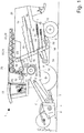
Fig. 1 :eine schematische Seitenansicht eines erfindungsgemäßen Mähdreschers. - Die Entleervorrichtung 25 besteht aus einem Auslaufrohr 28, welches um eine Achse 29 herum von einer in
Figur 1 dargestellten Transportstellung in eine Arbeitsstellung verschwenkbar ist, wobei die Arbeitsstellung beispielsweise in etwa rechtwinklig zur Zeichnungsebene liegt. In dem Auslaufrohr ist eine als mehrteilige Förderschnecke 30 ausgebildete Fördereinrichtung 31 angeordnet. Bei der Entleerung des Korntanks 24 wird das Erntegut mittels zweier in dem Korntank 24 angeordneten Querschnecken 32 der Förderschnecke 30 zugeführt. Zur Anpassung der Fördergeschwindigkeit der Förderschnecke 30 ist diese mit einem Getriebe 33 wirkverbunden, weiches die Antriebsenergie eines hier nicht dargestellten Antriebes auf die Förderschnecke 30 überträgt. Das Getriebe 33 ist beispielsweise als stufenloses Lastschaltgetriebe ausgebildet, so dass die Fördergeschwindigkeit der Förderschnecke 30 während ihres Betriebes variabel stufenlos veränderbar ist Dies hat den Vorteil, dass die Entleergeschwindigkeit und somit die Förderleistung bzw. das Fördervolumen der Fördereinrichtung 31 je nach Betriebsbedingungen anpassbar ist. Insbesondere während des Erntebetriebes des Mähdreschers 1 kann somit ein paralleler Überladeprozess des Erntegutes gezielt gesteuert werden.Bezugszeichenliste: 1 Mähdrescher 30 Förderschnecke 2 Getreideschneidwerk 31 Fördereinrichtung 3 Schrägförderer 32 Querförderschnecke 4 Querförderorgan 33 Getriebe 5 Überkehrgutstrom 6 Förderer 7 Dreschwerk 8 Dreschtrommel 9 Dreschkorb 10 Teilstrom 11 Teilstrom 12 Vorbereitungsboden 13 Siebebene 14 Reinigungseinheit 15 Gebläseeinheit 16 Fördereinrichtung 17 Strohleittrommel 18 Hordenschüttler 19 Abscheideorgan 20 Rücklaufboden 21 Körner 22 Körnerstrom 23 Förderelevator 24 Korntank 25 Entleervorrichtung 26 Maschinengehäuse 27 Fahrerkabine 28 Auslaufrohr 29 Achse
Der im rückwärtigen Bereich des Dreschwerks 7 aus diesem austretende weitere, im Wesentlichen aus Stroh und einem Restkornanteit bestehende Teilstrom 11 wird mittels einer Strohleittrommel 17 auf ein als Hordenschüttler 18 ausgeführtes Abscheideorgan 19 geleitet. Durch die Bewegung des Hordenschüttfers 18 wird ein großer Anteil der in der Strohschicht enthaltenen Körner 21 auf dem Hordenschüttler 18 abgeschieden und über einen sogenannten Rücklaufboden 20 und den Vorbereitungsboden 12 an die Reinigungseinheit 14 übergeben.
In der Reinigungseinheit 14 wird schließlich aus den in sie eingeleiteten verschiedenen Gutströmen 10, 21 ein gereinigter Körnerstrom 22 mittels Förderelevatoren 23 in einen Korntank 24 gefördert und dort zwischengespeichert. Die Entleerung des Korntanks 24 erfolgt in mittels einer Entleervorrichtung 25.
Der die Reinigungseinheit 14 zusätzlich verlassende und als Überkehrgutstrom 5 bezeichnete Massestrom besteht zum Einen aus Teilen des Erntegutes, die schwerer sind als die Spreu und auch schwerer als die Körner 21,22 selbst, so dass sie nicht von der Gebläseeinheit 15 aus dem Siebkasten geblasen werden können. Das sind unausgedroschene Ähren oder ungenügend entgrannte Körner, die deshalb erneut gedroschen werden müssen. Zum Anderen befinden sich aber auch einzelne Körner in dem Überkehrgutstrom 5. Der Überkehrgutstrom 5 wird durch eine Fördereinrichtung 16 dem Dreschwerk 7 erneut zugeführt.
Claims (9)
- Mähdrescher (1) mit einem Korntank (24) und einer dem Korntank (24) zugeordneten Entleervorrichtung (25), die zumindest aus einem schwenkbar an dem Mähdrescher (1) angeordneten Auslaufrohr (28) und zumindest einer in dem Auslaufrohr (28) angeordneten antreibbaren Fördereinrichtung (31) besteht, wobei die Fördergeschwindigkeit der Fördereinrichtung (31) variabel einstellbar ist, wobei Auswahl und/oder Anpassung der Fördergeschwindigkeit der Fördereinrichtung (31) selbsttätig erfolgt, dadurch gekennzeichnet, dass die selbsttätige Auswahl und/oder Anpassung der Fördergeschwindigkeit der Fördereinrichtung (31) in Abhängigkeit von Sensordaten erfolgt, und dass die Sensordaten mittels eines bilderfassenden Sensors mit entsprechender Bildauswertung erzeugt werden.
- Mähdrescher (1) nach Anspruch 1, dadurch gekennzeichnet, dass die Fördergeschwindigkeit der Fördereinrichtung (31) während des Erntebetriebes des Mähdreschers (1) variabel einstellbar ist.
- Mähdrescher (1) nach einem der vorstehenden Ansprüche, dadurch gekennzeichnet, dass die Fördergeschwindigkeit der Fördereinrichtung (31) vor dem Einschalten der Fördereinrichtung (31) vorwählbar ist und/oder dass die Fördergeschwindigkeit der Fördereinrichtung (31) während des Betreibens der Fördereinrichtung (31) veränderbar ist.
- Mähdrescher (1) nach einem der vorstehenden Ansprüche, dadurch gekennzeichnet, dass die Fördergeschwindigkeit der Fördereinrichtung (31) in Stufen oder stufenlos einstellbar ist.
- Mähdrescher (1) nach einem der vorstehenden Ansprüche, dadurch gekennzeichnet, dass die Einstellung der Fördergeschwindigkeit der Fördereinrichtung (31) mittels eines Getriebes (33) erfolgt.
- Mähdrescher (1) nach Anspruch 5, dadurch gekennzeichnet, dass das Getriebe (33) als Lastschaltgetriebe ausgebildet ist.
- Mähdrescher (1) nach einem der Ansprüche 5 oder 6, dadurch gekennzeichnet, dass das Getriebe (33) als Variator-Getriebe ausgebildet ist.
- Mähdrescher (1) nach einem der vorstehenden Ansprüche, dadurch gekennzeichnet, dass die Fördereinrichtung (31) durch zumindest eine Förderschnecke (30) und/oder zumindest ein endlos umlaufendes Förderband gebildet wird.
- Mähdrescher (1) nach einem der vorstehenden Ansprüche, dadurch gekennzeichnet, dass der Antrieb der Fördereinrichtung (31) mechanisch, hydraulisch und/oder elektromotorisch erfolgt.
Applications Claiming Priority (1)
| Application Number | Priority Date | Filing Date | Title |
|---|---|---|---|
| DE102008003758A DE102008003758A1 (de) | 2008-01-10 | 2008-01-10 | Mähdrescher |
Publications (3)
| Publication Number | Publication Date |
|---|---|
| EP2078451A2 EP2078451A2 (de) | 2009-07-15 |
| EP2078451A3 EP2078451A3 (de) | 2013-07-10 |
| EP2078451B1 true EP2078451B1 (de) | 2018-05-02 |
Family
ID=40521761
Family Applications (1)
| Application Number | Title | Priority Date | Filing Date |
|---|---|---|---|
| EP08166518.4A Not-in-force EP2078451B1 (de) | 2008-01-10 | 2008-10-14 | Mähdrescher |
Country Status (2)
| Country | Link |
|---|---|
| EP (1) | EP2078451B1 (de) |
| DE (1) | DE102008003758A1 (de) |
Cited By (1)
| Publication number | Priority date | Publication date | Assignee | Title |
|---|---|---|---|---|
| EP3922095A1 (de) * | 2020-06-10 | 2021-12-15 | CLAAS Selbstfahrende Erntemaschinen GmbH | Mähdrescher mit einer entleervorrichtung |
Families Citing this family (1)
| Publication number | Priority date | Publication date | Assignee | Title |
|---|---|---|---|---|
| CN115956432A (zh) * | 2023-01-30 | 2023-04-14 | 云南农业大学 | 水稻收割机 |
Family Cites Families (7)
| Publication number | Priority date | Publication date | Assignee | Title |
|---|---|---|---|---|
| DE4127117A1 (de) * | 1991-08-16 | 1993-02-18 | Deere & Co | Foerdersystem |
| DE19606730C2 (de) | 1996-02-23 | 1999-08-19 | Claas Ohg | Selbstfahrender Mähdrescher mit Korntank und Entleervorrichtung |
| US6339917B1 (en) * | 1998-03-18 | 2002-01-22 | Ben N. Dillon | Articulated combine |
| US6012272A (en) * | 1998-03-18 | 2000-01-11 | Dillon; Ben N. | Articulated combine |
| US6743093B1 (en) * | 2002-12-04 | 2004-06-01 | Deere & Co. | Auxiliary drive for combine augers for cleanout |
| CA2573086C (en) * | 2004-07-19 | 2013-12-24 | Lindsay David Hitch | A grain and fertiliser conveyer |
| US7452180B2 (en) * | 2004-10-29 | 2008-11-18 | Cnh America Llc | Grain tank unloader and clean out control |
-
2008
- 2008-01-10 DE DE102008003758A patent/DE102008003758A1/de not_active Withdrawn
- 2008-10-14 EP EP08166518.4A patent/EP2078451B1/de not_active Not-in-force
Non-Patent Citations (1)
| Title |
|---|
| None * |
Cited By (1)
| Publication number | Priority date | Publication date | Assignee | Title |
|---|---|---|---|---|
| EP3922095A1 (de) * | 2020-06-10 | 2021-12-15 | CLAAS Selbstfahrende Erntemaschinen GmbH | Mähdrescher mit einer entleervorrichtung |
Also Published As
| Publication number | Publication date |
|---|---|
| EP2078451A3 (de) | 2013-07-10 |
| EP2078451A2 (de) | 2009-07-15 |
| DE102008003758A1 (de) | 2009-07-16 |
Similar Documents
| Publication | Publication Date | Title |
|---|---|---|
| EP3662741B1 (de) | Landwirtschaftliche arbeitsmaschine sowie verfahren zum betreiben einer landwirtschaftlichen arbeitsmaschine | |
| EP1493318B1 (de) | Verfahren zur Steuerung eines Dreschwerks eines Mähdreschers | |
| DE602004005553T2 (de) | System zum Ausstossen von Ernteresten aus einem Mähdrescher | |
| DE60201993T2 (de) | Abschirmmittel für einen elevator einer landwirtschaftlichen erntemaschine | |
| DE102011085977A1 (de) | Sieb für eine Reinigungseinrichtung eines Mähdreschers | |
| EP2952085B1 (de) | Mähdrescher | |
| DE102020204859A1 (de) | Erntesteuerungssystem mit messerbalken-lasterfassung | |
| DE3822689C2 (de) | ||
| EP2845461A1 (de) | Anordnung zur Verlustmessung in einem Mähdrescher | |
| EP2425702B1 (de) | Mähdrescher | |
| DE102009000797B4 (de) | Siebanordnung für einen Mähdrescher | |
| EP4309490A1 (de) | Reinigungszusammenbau für einen mähdrescher | |
| EP2078451A2 (de) | Mähdrescher | |
| EP2848113A1 (de) | Reinigungseinrichtung für einen Mähdrescher | |
| DE102008023022A1 (de) | Mähdrescher | |
| DE102020123939A1 (de) | Rotierender siebkasten | |
| EP4470358A1 (de) | Selbstfahrender mähdrescher mit einem vorsatzgerät | |
| EP1894463B1 (de) | Landwirtschaftliche Erntemaschine mit einer Überladeeinrichtung | |
| BE1022970B1 (de) | Verstellanordnung zur Verstellung des Arbeitsspaltes eines Korbes einer Dresch- und/oder Trenneinrichtung | |
| EP2848112A1 (de) | Mähdrescher mit einer Abscheidevorrichtung | |
| EP1310151B1 (de) | Fördereinrichtung zur Befüllung eines Korntranks eines Mähdreschers und Überkehrförderer | |
| EP0091538B1 (de) | Mähdrescher mit Rückführeinrichtung | |
| EP4420506B1 (de) | Erntemaschine | |
| EP3915354B1 (de) | Entleersystem für eine landwirtschaftliche arbeitsmaschine | |
| DE4100844C2 (de) | Förderer einer Erntemaschine |
Legal Events
| Date | Code | Title | Description |
|---|---|---|---|
| PUAI | Public reference made under article 153(3) epc to a published international application that has entered the european phase |
Free format text: ORIGINAL CODE: 0009012 |
|
| AK | Designated contracting states |
Kind code of ref document: A2 Designated state(s): AT BE BG CH CY CZ DE DK EE ES FI FR GB GR HR HU IE IS IT LI LT LU LV MC MT NL NO PL PT RO SE SI SK TR |
|
| AX | Request for extension of the european patent |
Extension state: AL BA MK RS |
|
| PUAL | Search report despatched |
Free format text: ORIGINAL CODE: 0009013 |
|
| AK | Designated contracting states |
Kind code of ref document: A3 Designated state(s): AT BE BG CH CY CZ DE DK EE ES FI FR GB GR HR HU IE IS IT LI LT LU LV MC MT NL NO PL PT RO SE SI SK TR |
|
| AX | Request for extension of the european patent |
Extension state: AL BA MK RS |
|
| RIC1 | Information provided on ipc code assigned before grant |
Ipc: A01D 41/12 20060101AFI20130603BHEP |
|
| 17P | Request for examination filed |
Effective date: 20140110 |
|
| RBV | Designated contracting states (corrected) |
Designated state(s): AT BE BG CH CY CZ DE DK EE ES FI FR GB GR HR HU IE IS IT LI LT LU LV MC MT NL NO PL PT RO SE SI SK TR |
|
| AKX | Designation fees paid |
Designated state(s): AT BE BG CH CY CZ DE DK EE ES FI FR GB GR HR HU IE IS IT LI LT LU LV MC MT NL NO PL PT RO SE SI SK TR |
|
| 17Q | First examination report despatched |
Effective date: 20140307 |
|
| RAP1 | Party data changed (applicant data changed or rights of an application transferred) |
Owner name: CLAAS SELBSTFAHRENDE ERNTEMASCHINEN GMBH |
|
| GRAP | Despatch of communication of intention to grant a patent |
Free format text: ORIGINAL CODE: EPIDOSNIGR1 |
|
| STAA | Information on the status of an ep patent application or granted ep patent |
Free format text: STATUS: GRANT OF PATENT IS INTENDED |
|
| INTG | Intention to grant announced |
Effective date: 20180126 |
|
| RIN1 | Information on inventor provided before grant (corrected) |
Inventor name: VIEREGGE, CHRISTOPHER Inventor name: CLAES, ULRICH |
|
| GRAS | Grant fee paid |
Free format text: ORIGINAL CODE: EPIDOSNIGR3 |
|
| GRAA | (expected) grant |
Free format text: ORIGINAL CODE: 0009210 |
|
| STAA | Information on the status of an ep patent application or granted ep patent |
Free format text: STATUS: THE PATENT HAS BEEN GRANTED |
|
| AK | Designated contracting states |
Kind code of ref document: B1 Designated state(s): AT BE BG CH CY CZ DE DK EE ES FI FR GB GR HR HU IE IS IT LI LT LU LV MC MT NL NO PL PT RO SE SI SK TR |
|
| REG | Reference to a national code |
Ref country code: GB Ref legal event code: FG4D Free format text: NOT ENGLISH |
|
| REG | Reference to a national code |
Ref country code: CH Ref legal event code: EP Ref country code: AT Ref legal event code: REF Ref document number: 994225 Country of ref document: AT Kind code of ref document: T Effective date: 20180515 |
|
| REG | Reference to a national code |
Ref country code: DE Ref legal event code: R096 Ref document number: 502008016057 Country of ref document: DE |
|
| REG | Reference to a national code |
Ref country code: IE Ref legal event code: FG4D Free format text: LANGUAGE OF EP DOCUMENT: GERMAN |
|
| REG | Reference to a national code |
Ref country code: NL Ref legal event code: MP Effective date: 20180502 |
|
| REG | Reference to a national code |
Ref country code: LT Ref legal event code: MG4D |
|
| REG | Reference to a national code |
Ref country code: FR Ref legal event code: PLFP Year of fee payment: 11 |
|
| PG25 | Lapsed in a contracting state [announced via postgrant information from national office to epo] |
Ref country code: BG Free format text: LAPSE BECAUSE OF FAILURE TO SUBMIT A TRANSLATION OF THE DESCRIPTION OR TO PAY THE FEE WITHIN THE PRESCRIBED TIME-LIMIT Effective date: 20180802 Ref country code: FI Free format text: LAPSE BECAUSE OF FAILURE TO SUBMIT A TRANSLATION OF THE DESCRIPTION OR TO PAY THE FEE WITHIN THE PRESCRIBED TIME-LIMIT Effective date: 20180502 Ref country code: NO Free format text: LAPSE BECAUSE OF FAILURE TO SUBMIT A TRANSLATION OF THE DESCRIPTION OR TO PAY THE FEE WITHIN THE PRESCRIBED TIME-LIMIT Effective date: 20180802 Ref country code: ES Free format text: LAPSE BECAUSE OF FAILURE TO SUBMIT A TRANSLATION OF THE DESCRIPTION OR TO PAY THE FEE WITHIN THE PRESCRIBED TIME-LIMIT Effective date: 20180502 Ref country code: SE Free format text: LAPSE BECAUSE OF FAILURE TO SUBMIT A TRANSLATION OF THE DESCRIPTION OR TO PAY THE FEE WITHIN THE PRESCRIBED TIME-LIMIT Effective date: 20180502 Ref country code: LT Free format text: LAPSE BECAUSE OF FAILURE TO SUBMIT A TRANSLATION OF THE DESCRIPTION OR TO PAY THE FEE WITHIN THE PRESCRIBED TIME-LIMIT Effective date: 20180502 |
|
| PG25 | Lapsed in a contracting state [announced via postgrant information from national office to epo] |
Ref country code: LV Free format text: LAPSE BECAUSE OF FAILURE TO SUBMIT A TRANSLATION OF THE DESCRIPTION OR TO PAY THE FEE WITHIN THE PRESCRIBED TIME-LIMIT Effective date: 20180502 Ref country code: NL Free format text: LAPSE BECAUSE OF FAILURE TO SUBMIT A TRANSLATION OF THE DESCRIPTION OR TO PAY THE FEE WITHIN THE PRESCRIBED TIME-LIMIT Effective date: 20180502 Ref country code: GR Free format text: LAPSE BECAUSE OF FAILURE TO SUBMIT A TRANSLATION OF THE DESCRIPTION OR TO PAY THE FEE WITHIN THE PRESCRIBED TIME-LIMIT Effective date: 20180803 Ref country code: HR Free format text: LAPSE BECAUSE OF FAILURE TO SUBMIT A TRANSLATION OF THE DESCRIPTION OR TO PAY THE FEE WITHIN THE PRESCRIBED TIME-LIMIT Effective date: 20180502 |
|
| PG25 | Lapsed in a contracting state [announced via postgrant information from national office to epo] |
Ref country code: PT Free format text: LAPSE BECAUSE OF FAILURE TO SUBMIT A TRANSLATION OF THE DESCRIPTION OR TO PAY THE FEE WITHIN THE PRESCRIBED TIME-LIMIT Effective date: 20180903 |
|
| PG25 | Lapsed in a contracting state [announced via postgrant information from national office to epo] |
Ref country code: EE Free format text: LAPSE BECAUSE OF FAILURE TO SUBMIT A TRANSLATION OF THE DESCRIPTION OR TO PAY THE FEE WITHIN THE PRESCRIBED TIME-LIMIT Effective date: 20180502 Ref country code: PL Free format text: LAPSE BECAUSE OF FAILURE TO SUBMIT A TRANSLATION OF THE DESCRIPTION OR TO PAY THE FEE WITHIN THE PRESCRIBED TIME-LIMIT Effective date: 20180502 Ref country code: RO Free format text: LAPSE BECAUSE OF FAILURE TO SUBMIT A TRANSLATION OF THE DESCRIPTION OR TO PAY THE FEE WITHIN THE PRESCRIBED TIME-LIMIT Effective date: 20180502 Ref country code: CZ Free format text: LAPSE BECAUSE OF FAILURE TO SUBMIT A TRANSLATION OF THE DESCRIPTION OR TO PAY THE FEE WITHIN THE PRESCRIBED TIME-LIMIT Effective date: 20180502 Ref country code: SK Free format text: LAPSE BECAUSE OF FAILURE TO SUBMIT A TRANSLATION OF THE DESCRIPTION OR TO PAY THE FEE WITHIN THE PRESCRIBED TIME-LIMIT Effective date: 20180502 Ref country code: DK Free format text: LAPSE BECAUSE OF FAILURE TO SUBMIT A TRANSLATION OF THE DESCRIPTION OR TO PAY THE FEE WITHIN THE PRESCRIBED TIME-LIMIT Effective date: 20180502 |
|
| REG | Reference to a national code |
Ref country code: DE Ref legal event code: R097 Ref document number: 502008016057 Country of ref document: DE |
|
| PG25 | Lapsed in a contracting state [announced via postgrant information from national office to epo] |
Ref country code: IT Free format text: LAPSE BECAUSE OF FAILURE TO SUBMIT A TRANSLATION OF THE DESCRIPTION OR TO PAY THE FEE WITHIN THE PRESCRIBED TIME-LIMIT Effective date: 20180502 |
|
| PLBE | No opposition filed within time limit |
Free format text: ORIGINAL CODE: 0009261 |
|
| STAA | Information on the status of an ep patent application or granted ep patent |
Free format text: STATUS: NO OPPOSITION FILED WITHIN TIME LIMIT |
|
| 26N | No opposition filed |
Effective date: 20190205 |
|
| PG25 | Lapsed in a contracting state [announced via postgrant information from national office to epo] |
Ref country code: SI Free format text: LAPSE BECAUSE OF FAILURE TO SUBMIT A TRANSLATION OF THE DESCRIPTION OR TO PAY THE FEE WITHIN THE PRESCRIBED TIME-LIMIT Effective date: 20180502 |
|
| REG | Reference to a national code |
Ref country code: CH Ref legal event code: PL |
|
| GBPC | Gb: european patent ceased through non-payment of renewal fee |
Effective date: 20181014 |
|
| PG25 | Lapsed in a contracting state [announced via postgrant information from national office to epo] |
Ref country code: LU Free format text: LAPSE BECAUSE OF NON-PAYMENT OF DUE FEES Effective date: 20181014 Ref country code: MC Free format text: LAPSE BECAUSE OF FAILURE TO SUBMIT A TRANSLATION OF THE DESCRIPTION OR TO PAY THE FEE WITHIN THE PRESCRIBED TIME-LIMIT Effective date: 20180502 |
|
| REG | Reference to a national code |
Ref country code: IE Ref legal event code: MM4A |
|
| PG25 | Lapsed in a contracting state [announced via postgrant information from national office to epo] |
Ref country code: LI Free format text: LAPSE BECAUSE OF NON-PAYMENT OF DUE FEES Effective date: 20181031 Ref country code: CH Free format text: LAPSE BECAUSE OF NON-PAYMENT OF DUE FEES Effective date: 20181031 |
|
| PG25 | Lapsed in a contracting state [announced via postgrant information from national office to epo] |
Ref country code: IE Free format text: LAPSE BECAUSE OF NON-PAYMENT OF DUE FEES Effective date: 20181014 Ref country code: GB Free format text: LAPSE BECAUSE OF NON-PAYMENT OF DUE FEES Effective date: 20181014 |
|
| REG | Reference to a national code |
Ref country code: AT Ref legal event code: MM01 Ref document number: 994225 Country of ref document: AT Kind code of ref document: T Effective date: 20181014 |
|
| PG25 | Lapsed in a contracting state [announced via postgrant information from national office to epo] |
Ref country code: AT Free format text: LAPSE BECAUSE OF NON-PAYMENT OF DUE FEES Effective date: 20181014 Ref country code: MT Free format text: LAPSE BECAUSE OF FAILURE TO SUBMIT A TRANSLATION OF THE DESCRIPTION OR TO PAY THE FEE WITHIN THE PRESCRIBED TIME-LIMIT Effective date: 20180502 |
|
| PG25 | Lapsed in a contracting state [announced via postgrant information from national office to epo] |
Ref country code: TR Free format text: LAPSE BECAUSE OF FAILURE TO SUBMIT A TRANSLATION OF THE DESCRIPTION OR TO PAY THE FEE WITHIN THE PRESCRIBED TIME-LIMIT Effective date: 20180502 |
|
| PG25 | Lapsed in a contracting state [announced via postgrant information from national office to epo] |
Ref country code: HU Free format text: LAPSE BECAUSE OF FAILURE TO SUBMIT A TRANSLATION OF THE DESCRIPTION OR TO PAY THE FEE WITHIN THE PRESCRIBED TIME-LIMIT; INVALID AB INITIO Effective date: 20081014 Ref country code: CY Free format text: LAPSE BECAUSE OF FAILURE TO SUBMIT A TRANSLATION OF THE DESCRIPTION OR TO PAY THE FEE WITHIN THE PRESCRIBED TIME-LIMIT Effective date: 20180502 |
|
| PG25 | Lapsed in a contracting state [announced via postgrant information from national office to epo] |
Ref country code: IS Free format text: LAPSE BECAUSE OF FAILURE TO SUBMIT A TRANSLATION OF THE DESCRIPTION OR TO PAY THE FEE WITHIN THE PRESCRIBED TIME-LIMIT Effective date: 20180902 |
|
| PGFP | Annual fee paid to national office [announced via postgrant information from national office to epo] |
Ref country code: DE Payment date: 20211020 Year of fee payment: 14 |
|
| REG | Reference to a national code |
Ref country code: DE Ref legal event code: R119 Ref document number: 502008016057 Country of ref document: DE |
|
| P01 | Opt-out of the competence of the unified patent court (upc) registered |
Effective date: 20230515 |
|
| PG25 | Lapsed in a contracting state [announced via postgrant information from national office to epo] |
Ref country code: DE Free format text: LAPSE BECAUSE OF NON-PAYMENT OF DUE FEES Effective date: 20230503 |
|
| PGFP | Annual fee paid to national office [announced via postgrant information from national office to epo] |
Ref country code: FR Payment date: 20231024 Year of fee payment: 16 |
|
| PGFP | Annual fee paid to national office [announced via postgrant information from national office to epo] |
Ref country code: BE Payment date: 20231019 Year of fee payment: 16 |
|
| PG25 | Lapsed in a contracting state [announced via postgrant information from national office to epo] |
Ref country code: BE Free format text: LAPSE BECAUSE OF NON-PAYMENT OF DUE FEES Effective date: 20241031 |
|
| PG25 | Lapsed in a contracting state [announced via postgrant information from national office to epo] |
Ref country code: FR Free format text: LAPSE BECAUSE OF NON-PAYMENT OF DUE FEES Effective date: 20241031 |
|
| REG | Reference to a national code |
Ref country code: BE Ref legal event code: MM Effective date: 20241031 |