EP2078328B1 - Residual current device - Google Patents
Residual current device Download PDFInfo
- Publication number
- EP2078328B1 EP2078328B1 EP08701095A EP08701095A EP2078328B1 EP 2078328 B1 EP2078328 B1 EP 2078328B1 EP 08701095 A EP08701095 A EP 08701095A EP 08701095 A EP08701095 A EP 08701095A EP 2078328 B1 EP2078328 B1 EP 2078328B1
- Authority
- EP
- European Patent Office
- Prior art keywords
- current
- relay
- supply
- contacts
- voltage
- Prior art date
- Legal status (The legal status is an assumption and is not a legal conclusion. Google has not performed a legal analysis and makes no representation as to the accuracy of the status listed.)
- Not-in-force
Links
- 230000004044 response Effects 0.000 claims description 5
- 239000003990 capacitor Substances 0.000 abstract description 8
- 101000668165 Homo sapiens RNA-binding motif, single-stranded-interacting protein 1 Proteins 0.000 abstract description 7
- 102100039692 RNA-binding motif, single-stranded-interacting protein 1 Human genes 0.000 abstract description 7
- 230000005294 ferromagnetic effect Effects 0.000 description 8
- 101100365087 Arabidopsis thaliana SCRA gene Proteins 0.000 description 6
- 101150105073 SCR1 gene Proteins 0.000 description 6
- 101100134054 Saccharomyces cerevisiae (strain ATCC 204508 / S288c) NTG1 gene Proteins 0.000 description 6
- 230000001419 dependent effect Effects 0.000 description 6
- 230000008901 benefit Effects 0.000 description 5
- 238000010586 diagram Methods 0.000 description 5
- 230000005291 magnetic effect Effects 0.000 description 4
- 230000005672 electromagnetic field Effects 0.000 description 3
- 230000007935 neutral effect Effects 0.000 description 3
- XUIMIQQOPSSXEZ-UHFFFAOYSA-N Silicon Chemical compound [Si] XUIMIQQOPSSXEZ-UHFFFAOYSA-N 0.000 description 2
- 229910052710 silicon Inorganic materials 0.000 description 2
- 239000010703 silicon Substances 0.000 description 2
- 239000004020 conductor Substances 0.000 description 1
- 238000010276 construction Methods 0.000 description 1
- 230000008878 coupling Effects 0.000 description 1
- 238000010168 coupling process Methods 0.000 description 1
- 238000005859 coupling reaction Methods 0.000 description 1
- 238000001514 detection method Methods 0.000 description 1
- 230000000694 effects Effects 0.000 description 1
- 230000004907 flux Effects 0.000 description 1
- 230000007246 mechanism Effects 0.000 description 1
- 230000000116 mitigating effect Effects 0.000 description 1
- 230000009467 reduction Effects 0.000 description 1
- 238000004804 winding Methods 0.000 description 1
Images


Classifications
-
- H—ELECTRICITY
- H02—GENERATION; CONVERSION OR DISTRIBUTION OF ELECTRIC POWER
- H02H—EMERGENCY PROTECTIVE CIRCUIT ARRANGEMENTS
- H02H3/00—Emergency protective circuit arrangements for automatic disconnection directly responsive to an undesired change from normal electric working condition with or without subsequent reconnection ; integrated protection
- H02H3/26—Emergency protective circuit arrangements for automatic disconnection directly responsive to an undesired change from normal electric working condition with or without subsequent reconnection ; integrated protection responsive to difference between voltages or between currents; responsive to phase angle between voltages or between currents
- H02H3/32—Emergency protective circuit arrangements for automatic disconnection directly responsive to an undesired change from normal electric working condition with or without subsequent reconnection ; integrated protection responsive to difference between voltages or between currents; responsive to phase angle between voltages or between currents involving comparison of the voltage or current values at corresponding points in different conductors of a single system, e.g. of currents in go and return conductors
- H02H3/33—Emergency protective circuit arrangements for automatic disconnection directly responsive to an undesired change from normal electric working condition with or without subsequent reconnection ; integrated protection responsive to difference between voltages or between currents; responsive to phase angle between voltages or between currents involving comparison of the voltage or current values at corresponding points in different conductors of a single system, e.g. of currents in go and return conductors using summation current transformers
-
- H—ELECTRICITY
- H01—ELECTRIC ELEMENTS
- H01H—ELECTRIC SWITCHES; RELAYS; SELECTORS; EMERGENCY PROTECTIVE DEVICES
- H01H47/00—Circuit arrangements not adapted to a particular application of the relay and designed to obtain desired operating characteristics or to provide energising current
- H01H47/02—Circuit arrangements not adapted to a particular application of the relay and designed to obtain desired operating characteristics or to provide energising current for modifying the operation of the relay
- H01H47/04—Circuit arrangements not adapted to a particular application of the relay and designed to obtain desired operating characteristics or to provide energising current for modifying the operation of the relay for holding armature in attracted position, e.g. when initial energising circuit is interrupted; for maintaining armature in attracted position, e.g. with reduced energising current
- H01H47/043—Circuit arrangements not adapted to a particular application of the relay and designed to obtain desired operating characteristics or to provide energising current for modifying the operation of the relay for holding armature in attracted position, e.g. when initial energising circuit is interrupted; for maintaining armature in attracted position, e.g. with reduced energising current making use of an energy accumulator
-
- H—ELECTRICITY
- H02—GENERATION; CONVERSION OR DISTRIBUTION OF ELECTRIC POWER
- H02H—EMERGENCY PROTECTIVE CIRCUIT ARRANGEMENTS
- H02H1/00—Details of emergency protective circuit arrangements
- H02H1/06—Arrangements for supplying operative power
Definitions
- This invention relates to residual current devices.
- Residual current devices detect earth fault currents, which are also known as residual currents.
- the principle of operation of RCDs is very well known.
- VD RCDs can be grouped into two broad categories - voltage independent (VI) and voltage dependent (VD) types.
- VI types use the detected residual current as the source of energy to enable them to operate.
- VD types use the mains supply as the source of energy to enable them to operate.
- the VI types are commonly referred to as electromechanical types, and VD RCDs are often referred to as electronic types.
- RCDs can also be divided into two other categories - those that are mechanically or magnetically latched (ML) to enable them to be closed and remain closed (these include VD and VI types), and those that are electrically latched (EL) in that they require the mains supply to enable them to be closed and to remain closed.
- ML mechanically or magnetically latched
- EL electrically latched
- the EL types can be further subdivided into those that open automatically on loss of supply and remain open on restoration of the supply (for convenience here referred to as ELRO - electrically latched remains open), and those that open automatically on loss of supply but reclose automatically on restoration of the supply (for convenience here referred to as ELAR - electrically latched auto recloses).
- RCDs have advantages and disadvantages which users can take into consideration when selecting an RCD for a particular application.
- the VI type can operate down to virtually zero volts, but can be disabled under a double grounded neutral fault condition.
- the VDML uses electronic circuitry to provide for enhanced performance such as detection of pulsating DC fault currents, but can be disabled in the event of loss of supply neutral when used on a single phase supply. It should be noted that the risks involved in both of the above cases are generally considered to be very low and have not precluded the extensive use of such RCDs worldwide.
- the ELRO also uses electronic circuitry to provide for enhanced performance, and can protect motors from burn out under conditions of low supply voltage by auto tripping under these conditions.
- ELAR uses electronic circuitry to provide for enhanced performance, and can protect motors from burn out under conditions of low supply voltage by auto tripping under these conditions, and also auto recloses on restoration of supply.
- the ELAR would appear to be the ideal RCD.
- the need to enable such RCDs to open automatically on loss of supply and reclose automatically on restoration of the supply has to date required very sophisticated and bulky electronic circuitry and components to provide this functionality. These problems are seriously compounded by the additional requirement for these RCDs to remain open after opening in response to a residual current, even if the mains supply is temporarily removed and restored after such opening.
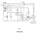
- FIG 1 is an example of a simple ELAR RCD.
- an AC mains supply is fed to a load L via two contacts SW1 of a relay RLA, the live and neutral mains conductors L, N passing through a current transformer CT en route to the load.
- the output of the CT is fed to an RCD integrated circuit (IC) 10.
- the function of the CT and IC 10 is to detect a current imbalance in the AC supply to the load indicative of a residual current, and when such an imbalance is detected to provide a high output voltage on the line 12 sufficient to turn on a silicon controlled rectifier SCR1.
- the construction and operation of such components are well known.
- the IC 10 may be a type WA050, supplied by Western Automation Research & Development and described in US Patent 7068047 .
- the RCD is powered from the mains via a bridge rectifier X1.
- the IC 10 is supplied with current via resistor R2.
- a solenoid SOL, a capacitor C1 and the relay RLA are connected in parallel to the bridge rectifier X1 via a resistor R1.
- the SCR1 which is normally held in a non-conducting state by a low voltage on the line 12 from the IC 10, is connected in series with the solenoid SOL.
- the relay contacts SW1 are normally open.
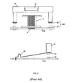
- An example of a suitable relay RLA is shown in Figure 2 .
- RLA comprises a bobbin 14 with a coil (not shown) wound on it.
- a ferromagnetic pole piece 16 extends through the bobbin, the top of the pole piece being positioned below a ferromagnetic element 18 fixed within a moving contact carrier 20.
- the contact carrier 20 and the moving contacts 22 are biased towards an open position away from fixed contacts 24 by a spring 26, so that a substantial air gap exists between the pole piece 16 and the ferromagnetic element 18.
- the coil has a relatively large number of turns in its winding so as to maximise the ampere turns providing electromagnetic energy.
- the relay RLA Prior to the application of power to the RCD, the relay RLA is de-energised and its contacts 22, 24 are open, so the mains supply is disconnected from the load L (the moving and fixed contacts 22, 24 constitute the contacts SW1 of Figure 1 ).
- the current through R1 will initially flow primarily to C1 to charge it up. As C1 acquires charge, more of the R1 current will be diverted into the RLA coil to establish an electromagnetic field which will be concentrated in the pole piece 16 and thereby provide an attracting force on the ferromagnetic element 18.
- the bias of the spring 26 will be overcome by the magnetic attraction between the pole piece 16 and the ferromagnetic element 18 and the contact carrier 20 will move automatically towards the pole piece 16 with the result that the contacts SW1 will close and thereby provide power to the load. Thereafter, C1 will sustain the RLA coil with current during the low voltage troughs of the rectified mains supply.
- a Zener diode ZD1 clamps the voltage on capacitor C1 to a safe level for the capacitor and the relay coil.
- the current through the RLA coil will be insufficient to keep the contact carrier 20 in the closed position, and the contact carrier and the contacts SW1 will automatically revert to the open position. If the mains voltage then increases to a sufficiently high level so as to reach or exceed the closing ampere turns current level, the relay RLA will be re-energised and its contacts SW1 will reclose automatically as before.
- the RLA coil will have a relatively large number of turns to enable it to achieve the required number of ampere turns to cause automatic closing of the contacts SW1. This results in the RLA coil having a relatively high impedance, typically a few thousand ohms.
- the solenoid SOL will have a relatively low impedance, typically less than 200 ohms, because it will only be energised momentarily as will be described later.
- the residual current device comprises a permanent magnet relay which is energised in response to an output from the current imbalance detecting circuit to open contacts in series with the firstmentioned relay to cut off the current flow through the latter.
- the permanent magnet relay is connected to the supply in parallel with the firstmentioned relay and has a normally-off further electronic switch in series therewith which is switched on by the output from the current imbalance detecting circuit to energise the permanent magnet relay.
- FIG. 3 mitigates the drawbacks of the arrangement of Figure 1 , and provides additional benefits.
- the RCD is powered via a diode D1 rather than a bridge rectifier.
- the solenoid SOL has been replaced by a permanent magnet relay PMR.
- the PMR contacts SW3 and a second silicon controlled rectifier SCR2 are connected in series with the relay RLA.
- a Zener diode ZD2 is connected between C1 and the gate of SCR2.
- the remainder of the circuit is substantially the same as that shown in Figure 1 .
- a schematic diagram of the PMR is shown in Figure 4 .
- the PMR comprises a bobbin 30 and a coil 32 wound on the bobbin.
- a ferromagnetic plunger 34 passes through the bore of the bobbin.
- One end of the plunger 34 is fitted with a reset button 36 which is biased downwardly (as seen in Figure 4 ) by a reset spring 42.
- the other (upper) end of the plunger 34 faces a permanent magnet 44 to which is fixed a moving contact 38, the moving contact 38 being biased into an open position away from a fixed contact 40 by a biasing means such as a spring, not shown.
- a biasing means such as a spring, not shown.
- the resistor R1 and the remaining charge on C1 will maintain a current flow through the RLA coil less than the closing current but greater than the holding current so as to keep RLA contacts SW1 closed.
- the current flow through the RLA coil will be reduced to a level at which it can no longer hold the RLA in the closed state, at which point the RLA contacts SW1 will open.
- the RLA contacts SW1 will automatically reclose.
- ZD2 provides a triggering means to facilitate automatic and controlled energisation of RLA and resultant closing of SW1 contacts.
- This triggering means may be achieved by other suitable devices, for example a diac.
- the closing current is substantially greater than the current required to maintain the relay in the closed position (the holding current).
- the holding current is substantially greater than the current required to maintain the relay in the closed position. This is because in the open state, a substantial air gap will exist between the relay pole piece and the ferromagnetic element coupled to the moving contacts, and this air gap will result in a high level of magnetic reluctance or resistance.
- the current flow through the relay coil in the open state has to generate sufficient electromagnetic force to overcome this reluctance and draw the ferromagnetic element to the closed position.
- the air gap will be substantially reduced with the result that magnetic reluctance will also be reduced. Because of this, it is possible to substantially reduce the current flow through the relay coil before the relay will revert to the open state.
- the difference between the closing current and the holding current can be greater than 80%.
- the current flow in the circuit of Figure 3 will be substantially less that that of the arrangement of Figure 1 , thereby resulting in a substantially reduced level of power dissipation.
- R1 size and rating can thereby be optimised solely for the purpose of providing RLA with its holding current.
- the voltage level at which RLA closes is largely determined by ZD2, which in turn ensures that the contacts can close at a consistent level of AC supply voltage.
- ZD2 The voltage level at which RLA closes is largely determined by ZD2, which in turn ensures that the contacts can close at a consistent level of AC supply voltage.
- a diode By drawing only the holding current from the mains supply, a diode can be used instead of a bridge rectifier.
- a bridge rectifier may be used to facilitate the use of an alternative relay and associated electronic components.
- the PMR has a stored energy device in the form of the permanent magnet 44 with the result that the PMR contacts 38, 40 can be latched by a very simple arrangement obviating the need for complex mechanical coupling, etc.
- the reset spring 42 provides the effective contact pressure, and the strength of the reset spring can be brought to a level just below the holding force of the permanent magnet. As a result, the energy required to open the PMR contacts will be very low and just sufficient to cause the permanent magnet to release its contact.
- the PMR contacts are located in a low voltage part of the circuit, mitigating problems of contact rating, dielectric strength, etc. In addition to minimising stress and improving the reliability of the contact releasing means, additional benefits accrue from the PMR in terms of its design, size and cost.
- Figure 5 with a sufficiently efficient PMR it is possible to dispense with the SCR1 and drive the PMR directly from the IC 10 via output 12. In this case, the PMR would not be directly dependent on any current flow from C1 or via R1. Capacitor C2 acquires a charge via R2, and provides the current flow through the PMR coil when the IC 10 output goes high.
Landscapes
- Engineering & Computer Science (AREA)
- Power Engineering (AREA)
- Relay Circuits (AREA)
- Breakers (AREA)
- Emergency Protection Circuit Devices (AREA)
- Driving Mechanisms And Operating Circuits Of Arc-Extinguishing High-Tension Switches (AREA)
- Processing Of Terminals (AREA)
Applications Claiming Priority (2)
| Application Number | Priority Date | Filing Date | Title |
|---|---|---|---|
| IES20070151 | 2007-03-07 | ||
| PCT/EP2008/000194 WO2008107035A1 (en) | 2007-03-07 | 2008-01-11 | Residual current device |
Publications (2)
| Publication Number | Publication Date |
|---|---|
| EP2078328A1 EP2078328A1 (en) | 2009-07-15 |
| EP2078328B1 true EP2078328B1 (en) | 2011-10-26 |
Family
ID=39273604
Family Applications (1)
| Application Number | Title | Priority Date | Filing Date |
|---|---|---|---|
| EP08701095A Not-in-force EP2078328B1 (en) | 2007-03-07 | 2008-01-11 | Residual current device |
Country Status (9)
Families Citing this family (12)
| Publication number | Priority date | Publication date | Assignee | Title |
|---|---|---|---|---|
| WO2012110279A1 (en) * | 2011-02-15 | 2012-08-23 | Shakira Limited | Electromechanical relay circuit |
| WO2012131508A1 (en) * | 2011-03-30 | 2012-10-04 | Shakira Limited | A device for detecting a fault in an ac supply |
| EP2725599A1 (en) | 2012-10-23 | 2014-04-30 | Shakira Limited | An electromechanical switching circuit with memory |
| AU2013231082B2 (en) * | 2012-10-23 | 2014-12-11 | Shakira Limited | An electromechanical switching circuit with memory |
| GB2521872A (en) * | 2014-01-07 | 2015-07-08 | Tripco Ltd | An electrical fault protection device |
| JP6540203B2 (ja) * | 2015-04-30 | 2019-07-10 | マックス株式会社 | 設備機器 |
| DE102016117004A1 (de) | 2016-09-09 | 2018-03-15 | Eaton Industries (Austria) Gmbh | Schutzschaltgerät |
| DE102016117006A1 (de) * | 2016-09-09 | 2018-03-15 | Eaton Industries (Austria) Gmbh | Schutzschaltgerät |
| EP3518384B1 (en) * | 2016-10-27 | 2021-12-15 | Murata Manufacturing Co., Ltd. | Power supply device and power storage device |
| EP3531551B1 (en) * | 2018-02-27 | 2023-05-24 | KNORR-BREMSE Systeme für Nutzfahrzeuge GmbH | Device and method to reduce clutch engagement speed |
| KR102701972B1 (ko) * | 2024-02-20 | 2024-09-04 | 미래아이씨티 주식회사 | 귀환 제어 방식의 양방향 누전 차단기 |
| CN119994793B (zh) * | 2025-04-15 | 2025-06-13 | 南方电网科学研究院有限责任公司 | 低压台区的配电保护方法、装置、计算机设备和存储介质 |
Family Cites Families (10)
| Publication number | Priority date | Publication date | Assignee | Title |
|---|---|---|---|---|
| US4042967A (en) * | 1975-10-28 | 1977-08-16 | Yujiro Yamamoto | Ground fault sensor |
| US4707759A (en) * | 1985-02-27 | 1987-11-17 | Bodkin Lawrence E | Universal fault circuit interrupter |
| JP2880331B2 (ja) * | 1991-09-20 | 1999-04-05 | 株式会社日立製作所 | 漏電警報付遮断器 |
| US5661623A (en) * | 1993-09-02 | 1997-08-26 | Hubbell Corporation | Ground fault circuit interrupter plug |
| JP2000106077A (ja) * | 1998-09-30 | 2000-04-11 | Tempearl Ind Co Ltd | 漏電リレー |
| US6052266A (en) * | 1998-10-01 | 2000-04-18 | Tower Manufacturing Corporation | Ground fault circuit interrupter |
| IES20020199A2 (en) * | 2002-03-21 | 2003-08-06 | Tripco Ltd | Resettable switching device |
| JP2005243352A (ja) * | 2004-02-25 | 2005-09-08 | Hitachi Industrial Equipment Systems Co Ltd | 漏電リレー |
| JP4683950B2 (ja) * | 2004-05-11 | 2011-05-18 | 株式会社リコー | スイッチ装置及び電気機器 |
| IES20040539A2 (en) * | 2004-08-11 | 2006-02-22 | Shakira Ltd | A residual current device with double grounded neutral fault detection |
-
2008
- 2008-01-11 EP EP08701095A patent/EP2078328B1/en not_active Not-in-force
- 2008-01-11 CN CN2008800025976A patent/CN101589528B/zh not_active Expired - Fee Related
- 2008-01-11 JP JP2009552079A patent/JP5055387B2/ja not_active Expired - Fee Related
- 2008-01-11 ES ES08701095T patent/ES2374414T3/es active Active
- 2008-01-11 US US12/312,508 patent/US7916438B2/en not_active Expired - Fee Related
- 2008-01-11 WO PCT/EP2008/000194 patent/WO2008107035A1/en active Application Filing
- 2008-01-11 AU AU2008224232A patent/AU2008224232B2/en not_active Ceased
- 2008-01-11 DK DK08701095.5T patent/DK2078328T3/da active
- 2008-01-11 AT AT08701095T patent/ATE531109T1/de not_active IP Right Cessation
Also Published As
| Publication number | Publication date |
|---|---|
| EP2078328A1 (en) | 2009-07-15 |
| ATE531109T1 (de) | 2011-11-15 |
| WO2008107035A1 (en) | 2008-09-12 |
| CN101589528A (zh) | 2009-11-25 |
| US7916438B2 (en) | 2011-03-29 |
| AU2008224232B2 (en) | 2010-12-16 |
| US20100046127A1 (en) | 2010-02-25 |
| CN101589528B (zh) | 2012-09-26 |
| AU2008224232A1 (en) | 2008-09-12 |
| JP5055387B2 (ja) | 2012-10-24 |
| ES2374414T3 (es) | 2012-02-16 |
| DK2078328T3 (da) | 2012-02-06 |
| JP2010520592A (ja) | 2010-06-10 |
Similar Documents
| Publication | Publication Date | Title |
|---|---|---|
| EP2078328B1 (en) | Residual current device | |
| CN101467322B (zh) | 具有电压相关和电压无关工作模式的漏电保护设备 | |
| US4063299A (en) | Magnetically latched ground fault circuit interrupter | |
| US20080151463A1 (en) | Apparatus and method for controlling a circuit breaker trip device | |
| WO1997018611A2 (en) | Energy validation arrangement for a self-powered circuit interrupter | |
| EP2445074B1 (en) | A fault detecting device for electrical installations and equipment | |
| WO1997018611A9 (en) | Energy validation arrangement for a self-powered circuit interrupter | |
| US8976494B2 (en) | Device for detecting a fault in an AC supply | |
| WO2012131508A1 (en) | A device for detecting a fault in an ac supply | |
| WO2013139521A1 (en) | An electromagnetic switch for use with electrical equipment | |
| EP3104482B1 (en) | A device for detecting a ground fault in an ac supply and load shedding disabled during self-test | |
| CA3025101A1 (en) | Circuit interrupter providing grounded neutral protection and method of controlling the same | |
| US10163597B2 (en) | Energy-saving ground-fault circuit interrupter | |
| KR100483931B1 (ko) | 과부하차단기의 트립장치 | |
| WO2012110279A1 (en) | Electromechanical relay circuit | |
| CN110690682B (zh) | 用于拒绝向电气布线设备中的螺线管供电的电路和方法 | |
| CN109690718A (zh) | 电磁操作机构的驱动电路 | |
| EP0403216A2 (en) | Electromagnetic actuator arrangement | |
| KR200313673Y1 (ko) | 과부하차단기의 트립장치 | |
| JP3127678B2 (ja) | 直流高速度遮断器 | |
| GB2377834A (en) | Residual current device with neutral loss protection | |
| IE20020242A1 (en) | Residual current device | |
| JP2001267125A (ja) | 電磁石装置、励磁用回路、及び電磁石応用機器 |
Legal Events
| Date | Code | Title | Description |
|---|---|---|---|
| PUAI | Public reference made under article 153(3) epc to a published international application that has entered the european phase |
Free format text: ORIGINAL CODE: 0009012 |
|
| 17P | Request for examination filed |
Effective date: 20090420 |
|
| AK | Designated contracting states |
Kind code of ref document: A1 Designated state(s): AT BE BG CH CY CZ DE DK EE ES FI FR GB GR HR HU IE IS IT LI LT LU LV MC MT NL NO PL PT RO SE SI SK TR |
|
| GRAP | Despatch of communication of intention to grant a patent |
Free format text: ORIGINAL CODE: EPIDOSNIGR1 |
|
| GRAS | Grant fee paid |
Free format text: ORIGINAL CODE: EPIDOSNIGR3 |
|
| GRAA | (expected) grant |
Free format text: ORIGINAL CODE: 0009210 |
|
| AK | Designated contracting states |
Kind code of ref document: B1 Designated state(s): AT BE BG CH CY CZ DE DK EE ES FI FR GB GR HR HU IE IS IT LI LT LU LV MC MT NL NO PL PT RO SE SI SK TR |
|
| DAX | Request for extension of the european patent (deleted) | ||
| REG | Reference to a national code |
Ref country code: GB Ref legal event code: FG4D |
|
| REG | Reference to a national code |
Ref country code: CH Ref legal event code: EP |
|
| REG | Reference to a national code |
Ref country code: IE Ref legal event code: FG4D |
|
| REG | Reference to a national code |
Ref country code: CH Ref legal event code: NV Representative=s name: CRONIN INTELLECTUAL PROPERTY |
|
| REG | Reference to a national code |
Ref country code: DE Ref legal event code: R096 Ref document number: 602008010824 Country of ref document: DE Effective date: 20120119 |
|
| REG | Reference to a national code |
Ref country code: DK Ref legal event code: T3 |
|
| REG | Reference to a national code |
Ref country code: SE Ref legal event code: TRGR |
|
| REG | Reference to a national code |
Ref country code: NO Ref legal event code: T2 Effective date: 20111026 |
|
| REG | Reference to a national code |
Ref country code: NL Ref legal event code: VDEP Effective date: 20111026 |
|
| REG | Reference to a national code |
Ref country code: ES Ref legal event code: FG2A Ref document number: 2374414 Country of ref document: ES Kind code of ref document: T3 Effective date: 20120216 |
|
| LTIE | Lt: invalidation of european patent or patent extension |
Effective date: 20111026 |
|
| REG | Reference to a national code |
Ref country code: AT Ref legal event code: MK05 Ref document number: 531109 Country of ref document: AT Kind code of ref document: T Effective date: 20111026 |
|
| PG25 | Lapsed in a contracting state [announced via postgrant information from national office to epo] |
Ref country code: BE Free format text: LAPSE BECAUSE OF FAILURE TO SUBMIT A TRANSLATION OF THE DESCRIPTION OR TO PAY THE FEE WITHIN THE PRESCRIBED TIME-LIMIT Effective date: 20111026 Ref country code: IS Free format text: LAPSE BECAUSE OF FAILURE TO SUBMIT A TRANSLATION OF THE DESCRIPTION OR TO PAY THE FEE WITHIN THE PRESCRIBED TIME-LIMIT Effective date: 20120226 Ref country code: LT Free format text: LAPSE BECAUSE OF FAILURE TO SUBMIT A TRANSLATION OF THE DESCRIPTION OR TO PAY THE FEE WITHIN THE PRESCRIBED TIME-LIMIT Effective date: 20111026 |
|
| PG25 | Lapsed in a contracting state [announced via postgrant information from national office to epo] |
Ref country code: PT Free format text: LAPSE BECAUSE OF FAILURE TO SUBMIT A TRANSLATION OF THE DESCRIPTION OR TO PAY THE FEE WITHIN THE PRESCRIBED TIME-LIMIT Effective date: 20120227 Ref country code: LV Free format text: LAPSE BECAUSE OF FAILURE TO SUBMIT A TRANSLATION OF THE DESCRIPTION OR TO PAY THE FEE WITHIN THE PRESCRIBED TIME-LIMIT Effective date: 20111026 Ref country code: GR Free format text: LAPSE BECAUSE OF FAILURE TO SUBMIT A TRANSLATION OF THE DESCRIPTION OR TO PAY THE FEE WITHIN THE PRESCRIBED TIME-LIMIT Effective date: 20120127 Ref country code: HR Free format text: LAPSE BECAUSE OF FAILURE TO SUBMIT A TRANSLATION OF THE DESCRIPTION OR TO PAY THE FEE WITHIN THE PRESCRIBED TIME-LIMIT Effective date: 20111026 Ref country code: SI Free format text: LAPSE BECAUSE OF FAILURE TO SUBMIT A TRANSLATION OF THE DESCRIPTION OR TO PAY THE FEE WITHIN THE PRESCRIBED TIME-LIMIT Effective date: 20111026 Ref country code: NL Free format text: LAPSE BECAUSE OF FAILURE TO SUBMIT A TRANSLATION OF THE DESCRIPTION OR TO PAY THE FEE WITHIN THE PRESCRIBED TIME-LIMIT Effective date: 20111026 Ref country code: PL Free format text: LAPSE BECAUSE OF FAILURE TO SUBMIT A TRANSLATION OF THE DESCRIPTION OR TO PAY THE FEE WITHIN THE PRESCRIBED TIME-LIMIT Effective date: 20111026 |
|
| PG25 | Lapsed in a contracting state [announced via postgrant information from national office to epo] |
Ref country code: CY Free format text: LAPSE BECAUSE OF FAILURE TO SUBMIT A TRANSLATION OF THE DESCRIPTION OR TO PAY THE FEE WITHIN THE PRESCRIBED TIME-LIMIT Effective date: 20111026 |
|
| PGFP | Annual fee paid to national office [announced via postgrant information from national office to epo] |
Ref country code: IT Payment date: 20120117 Year of fee payment: 5 |
|
| PG25 | Lapsed in a contracting state [announced via postgrant information from national office to epo] |
Ref country code: SK Free format text: LAPSE BECAUSE OF FAILURE TO SUBMIT A TRANSLATION OF THE DESCRIPTION OR TO PAY THE FEE WITHIN THE PRESCRIBED TIME-LIMIT Effective date: 20111026 Ref country code: CZ Free format text: LAPSE BECAUSE OF FAILURE TO SUBMIT A TRANSLATION OF THE DESCRIPTION OR TO PAY THE FEE WITHIN THE PRESCRIBED TIME-LIMIT Effective date: 20111026 Ref country code: EE Free format text: LAPSE BECAUSE OF FAILURE TO SUBMIT A TRANSLATION OF THE DESCRIPTION OR TO PAY THE FEE WITHIN THE PRESCRIBED TIME-LIMIT Effective date: 20111026 Ref country code: BG Free format text: LAPSE BECAUSE OF FAILURE TO SUBMIT A TRANSLATION OF THE DESCRIPTION OR TO PAY THE FEE WITHIN THE PRESCRIBED TIME-LIMIT Effective date: 20120126 |
|
| PG25 | Lapsed in a contracting state [announced via postgrant information from national office to epo] |
Ref country code: MC Free format text: LAPSE BECAUSE OF NON-PAYMENT OF DUE FEES Effective date: 20120131 Ref country code: RO Free format text: LAPSE BECAUSE OF FAILURE TO SUBMIT A TRANSLATION OF THE DESCRIPTION OR TO PAY THE FEE WITHIN THE PRESCRIBED TIME-LIMIT Effective date: 20111026 |
|
| PLBE | No opposition filed within time limit |
Free format text: ORIGINAL CODE: 0009261 |
|
| STAA | Information on the status of an ep patent application or granted ep patent |
Free format text: STATUS: NO OPPOSITION FILED WITHIN TIME LIMIT |
|
| 26N | No opposition filed |
Effective date: 20120727 |
|
| REG | Reference to a national code |
Ref country code: DE Ref legal event code: R097 Ref document number: 602008010824 Country of ref document: DE Effective date: 20120727 |
|
| PG25 | Lapsed in a contracting state [announced via postgrant information from national office to epo] |
Ref country code: AT Free format text: LAPSE BECAUSE OF FAILURE TO SUBMIT A TRANSLATION OF THE DESCRIPTION OR TO PAY THE FEE WITHIN THE PRESCRIBED TIME-LIMIT Effective date: 20111026 |
|
| PGFP | Annual fee paid to national office [announced via postgrant information from national office to epo] |
Ref country code: IE Payment date: 20121105 Year of fee payment: 6 |
|
| PGFP | Annual fee paid to national office [announced via postgrant information from national office to epo] |
Ref country code: SE Payment date: 20130122 Year of fee payment: 6 Ref country code: DE Payment date: 20130320 Year of fee payment: 6 Ref country code: DK Payment date: 20130124 Year of fee payment: 6 Ref country code: CH Payment date: 20130123 Year of fee payment: 6 |
|
| PG25 | Lapsed in a contracting state [announced via postgrant information from national office to epo] |
Ref country code: MT Free format text: LAPSE BECAUSE OF FAILURE TO SUBMIT A TRANSLATION OF THE DESCRIPTION OR TO PAY THE FEE WITHIN THE PRESCRIBED TIME-LIMIT Effective date: 20111026 |
|
| PG25 | Lapsed in a contracting state [announced via postgrant information from national office to epo] |
Ref country code: TR Free format text: LAPSE BECAUSE OF FAILURE TO SUBMIT A TRANSLATION OF THE DESCRIPTION OR TO PAY THE FEE WITHIN THE PRESCRIBED TIME-LIMIT Effective date: 20111026 |
|
| PG25 | Lapsed in a contracting state [announced via postgrant information from national office to epo] |
Ref country code: LU Free format text: LAPSE BECAUSE OF NON-PAYMENT OF DUE FEES Effective date: 20120111 |
|
| PG25 | Lapsed in a contracting state [announced via postgrant information from national office to epo] |
Ref country code: HU Free format text: LAPSE BECAUSE OF FAILURE TO SUBMIT A TRANSLATION OF THE DESCRIPTION OR TO PAY THE FEE WITHIN THE PRESCRIBED TIME-LIMIT Effective date: 20080111 |
|
| REG | Reference to a national code |
Ref country code: DE Ref legal event code: R119 Ref document number: 602008010824 Country of ref document: DE |
|
| REG | Reference to a national code |
Ref country code: CH Ref legal event code: PL |
|
| REG | Reference to a national code |
Ref country code: DK Ref legal event code: EBP Effective date: 20140131 |
|
| REG | Reference to a national code |
Ref country code: SE Ref legal event code: EUG |
|
| REG | Reference to a national code |
Ref country code: DE Ref legal event code: R119 Ref document number: 602008010824 Country of ref document: DE Effective date: 20140801 |
|
| PG25 | Lapsed in a contracting state [announced via postgrant information from national office to epo] |
Ref country code: LI Free format text: LAPSE BECAUSE OF NON-PAYMENT OF DUE FEES Effective date: 20140131 Ref country code: CH Free format text: LAPSE BECAUSE OF NON-PAYMENT OF DUE FEES Effective date: 20140131 Ref country code: DE Free format text: LAPSE BECAUSE OF NON-PAYMENT OF DUE FEES Effective date: 20140801 |
|
| REG | Reference to a national code |
Ref country code: IE Ref legal event code: MM4A |
|
| PG25 | Lapsed in a contracting state [announced via postgrant information from national office to epo] |
Ref country code: SE Free format text: LAPSE BECAUSE OF NON-PAYMENT OF DUE FEES Effective date: 20140112 |
|
| REG | Reference to a national code |
Ref country code: FR Ref legal event code: PLFP Year of fee payment: 8 |
|
| PG25 | Lapsed in a contracting state [announced via postgrant information from national office to epo] |
Ref country code: DK Free format text: LAPSE BECAUSE OF NON-PAYMENT OF DUE FEES Effective date: 20140131 Ref country code: IE Free format text: LAPSE BECAUSE OF NON-PAYMENT OF DUE FEES Effective date: 20140111 |
|
| PGFP | Annual fee paid to national office [announced via postgrant information from national office to epo] |
Ref country code: NO Payment date: 20150127 Year of fee payment: 8 Ref country code: ES Payment date: 20150225 Year of fee payment: 8 Ref country code: FI Payment date: 20150126 Year of fee payment: 8 |
|
| PGFP | Annual fee paid to national office [announced via postgrant information from national office to epo] |
Ref country code: GB Payment date: 20150128 Year of fee payment: 8 Ref country code: FR Payment date: 20150129 Year of fee payment: 8 |
|
| PG25 | Lapsed in a contracting state [announced via postgrant information from national office to epo] |
Ref country code: IT Free format text: LAPSE BECAUSE OF NON-PAYMENT OF DUE FEES Effective date: 20140111 |
|
| REG | Reference to a national code |
Ref country code: NO Ref legal event code: MMEP |
|
| GBPC | Gb: european patent ceased through non-payment of renewal fee |
Effective date: 20160111 |
|
| REG | Reference to a national code |
Ref country code: FR Ref legal event code: ST Effective date: 20160930 |
|
| PG25 | Lapsed in a contracting state [announced via postgrant information from national office to epo] |
Ref country code: FI Free format text: LAPSE BECAUSE OF NON-PAYMENT OF DUE FEES Effective date: 20160111 Ref country code: GB Free format text: LAPSE BECAUSE OF NON-PAYMENT OF DUE FEES Effective date: 20160111 Ref country code: NO Free format text: LAPSE BECAUSE OF NON-PAYMENT OF DUE FEES Effective date: 20160131 |
|
| PG25 | Lapsed in a contracting state [announced via postgrant information from national office to epo] |
Ref country code: FR Free format text: LAPSE BECAUSE OF NON-PAYMENT OF DUE FEES Effective date: 20160201 |
|
| PG25 | Lapsed in a contracting state [announced via postgrant information from national office to epo] |
Ref country code: ES Free format text: LAPSE BECAUSE OF NON-PAYMENT OF DUE FEES Effective date: 20160112 |
|
| REG | Reference to a national code |
Ref country code: ES Ref legal event code: FD2A Effective date: 20181207 |