EP2077376B1 - Rotor blade attachment in a gas turbine - Google Patents
Rotor blade attachment in a gas turbine Download PDFInfo
- Publication number
- EP2077376B1 EP2077376B1 EP09250001.6A EP09250001A EP2077376B1 EP 2077376 B1 EP2077376 B1 EP 2077376B1 EP 09250001 A EP09250001 A EP 09250001A EP 2077376 B1 EP2077376 B1 EP 2077376B1
- Authority
- EP
- European Patent Office
- Prior art keywords
- clamp
- looped portion
- rotor blade
- plug
- recited
- Prior art date
- Legal status (The legal status is an assumption and is not a legal conclusion. Google has not performed a legal analysis and makes no representation as to the accuracy of the status listed.)
- Active
Links
- 239000002131 composite material Substances 0.000 claims description 14
- 230000006835 compression Effects 0.000 claims description 13
- 238000007906 compression Methods 0.000 claims description 13
- 239000011153 ceramic matrix composite Substances 0.000 claims description 8
- 238000000034 method Methods 0.000 claims description 5
- 239000002184 metal Substances 0.000 claims description 3
- 229910052751 metal Inorganic materials 0.000 claims description 3
- 239000000919 ceramic Substances 0.000 claims description 2
- 238000004026 adhesive bonding Methods 0.000 claims 2
- 239000007789 gas Substances 0.000 description 22
- 239000000567 combustion gas Substances 0.000 description 6
- 230000008901 benefit Effects 0.000 description 4
- 239000000284 extract Substances 0.000 description 4
- 230000003993 interaction Effects 0.000 description 4
- 239000000463 material Substances 0.000 description 4
- 239000007769 metal material Substances 0.000 description 3
- 238000001816 cooling Methods 0.000 description 2
- 239000000835 fiber Substances 0.000 description 2
- 239000000446 fuel Substances 0.000 description 2
- 239000011159 matrix material Substances 0.000 description 2
- OKTJSMMVPCPJKN-UHFFFAOYSA-N Carbon Chemical compound [C] OKTJSMMVPCPJKN-UHFFFAOYSA-N 0.000 description 1
- 229910001069 Ti alloy Inorganic materials 0.000 description 1
- 230000004888 barrier function Effects 0.000 description 1
- 229910052799 carbon Inorganic materials 0.000 description 1
- 229910010293 ceramic material Inorganic materials 0.000 description 1
- 238000010276 construction Methods 0.000 description 1
- 239000004744 fabric Substances 0.000 description 1
- 230000002349 favourable effect Effects 0.000 description 1
- 238000003754 machining Methods 0.000 description 1
- 230000007246 mechanism Effects 0.000 description 1
- 238000012986 modification Methods 0.000 description 1
- 230000004048 modification Effects 0.000 description 1
- 229920001296 polysiloxane Polymers 0.000 description 1
- 239000011208 reinforced composite material Substances 0.000 description 1
- 239000002759 woven fabric Substances 0.000 description 1
Images


Classifications
-
- F—MECHANICAL ENGINEERING; LIGHTING; HEATING; WEAPONS; BLASTING
- F01—MACHINES OR ENGINES IN GENERAL; ENGINE PLANTS IN GENERAL; STEAM ENGINES
- F01D—NON-POSITIVE DISPLACEMENT MACHINES OR ENGINES, e.g. STEAM TURBINES
- F01D5/00—Blades; Blade-carrying members; Heating, heat-insulating, cooling or antivibration means on the blades or the members
- F01D5/30—Fixing blades to rotors; Blade roots ; Blade spacers
- F01D5/3007—Fixing blades to rotors; Blade roots ; Blade spacers of axial insertion type
-
- F—MECHANICAL ENGINEERING; LIGHTING; HEATING; WEAPONS; BLASTING
- F01—MACHINES OR ENGINES IN GENERAL; ENGINE PLANTS IN GENERAL; STEAM ENGINES
- F01D—NON-POSITIVE DISPLACEMENT MACHINES OR ENGINES, e.g. STEAM TURBINES
- F01D5/00—Blades; Blade-carrying members; Heating, heat-insulating, cooling or antivibration means on the blades or the members
- F01D5/30—Fixing blades to rotors; Blade roots ; Blade spacers
- F01D5/3084—Fixing blades to rotors; Blade roots ; Blade spacers the blades being made of ceramics
-
- F—MECHANICAL ENGINEERING; LIGHTING; HEATING; WEAPONS; BLASTING
- F01—MACHINES OR ENGINES IN GENERAL; ENGINE PLANTS IN GENERAL; STEAM ENGINES
- F01D—NON-POSITIVE DISPLACEMENT MACHINES OR ENGINES, e.g. STEAM TURBINES
- F01D5/00—Blades; Blade-carrying members; Heating, heat-insulating, cooling or antivibration means on the blades or the members
- F01D5/30—Fixing blades to rotors; Blade roots ; Blade spacers
- F01D5/3092—Protective layers between blade root and rotor disc surfaces, e.g. anti-friction layers
-
- F—MECHANICAL ENGINEERING; LIGHTING; HEATING; WEAPONS; BLASTING
- F05—INDEXING SCHEMES RELATING TO ENGINES OR PUMPS IN VARIOUS SUBCLASSES OF CLASSES F01-F04
- F05D—INDEXING SCHEME FOR ASPECTS RELATING TO NON-POSITIVE-DISPLACEMENT MACHINES OR ENGINES, GAS-TURBINES OR JET-PROPULSION PLANTS
- F05D2230/00—Manufacture
- F05D2230/60—Assembly methods
-
- F—MECHANICAL ENGINEERING; LIGHTING; HEATING; WEAPONS; BLASTING
- F05—INDEXING SCHEMES RELATING TO ENGINES OR PUMPS IN VARIOUS SUBCLASSES OF CLASSES F01-F04
- F05D—INDEXING SCHEME FOR ASPECTS RELATING TO NON-POSITIVE-DISPLACEMENT MACHINES OR ENGINES, GAS-TURBINES OR JET-PROPULSION PLANTS
- F05D2250/00—Geometry
- F05D2250/10—Two-dimensional
- F05D2250/18—Two-dimensional patterned
- F05D2250/182—Two-dimensional patterned crenellated, notched
-
- F—MECHANICAL ENGINEERING; LIGHTING; HEATING; WEAPONS; BLASTING
- F05—INDEXING SCHEMES RELATING TO ENGINES OR PUMPS IN VARIOUS SUBCLASSES OF CLASSES F01-F04
- F05D—INDEXING SCHEME FOR ASPECTS RELATING TO NON-POSITIVE-DISPLACEMENT MACHINES OR ENGINES, GAS-TURBINES OR JET-PROPULSION PLANTS
- F05D2250/00—Geometry
- F05D2250/70—Shape
- F05D2250/71—Shape curved
-
- F—MECHANICAL ENGINEERING; LIGHTING; HEATING; WEAPONS; BLASTING
- F05—INDEXING SCHEMES RELATING TO ENGINES OR PUMPS IN VARIOUS SUBCLASSES OF CLASSES F01-F04
- F05D—INDEXING SCHEME FOR ASPECTS RELATING TO NON-POSITIVE-DISPLACEMENT MACHINES OR ENGINES, GAS-TURBINES OR JET-PROPULSION PLANTS
- F05D2260/00—Function
- F05D2260/30—Retaining components in desired mutual position
-
- F—MECHANICAL ENGINEERING; LIGHTING; HEATING; WEAPONS; BLASTING
- F05—INDEXING SCHEMES RELATING TO ENGINES OR PUMPS IN VARIOUS SUBCLASSES OF CLASSES F01-F04
- F05D—INDEXING SCHEME FOR ASPECTS RELATING TO NON-POSITIVE-DISPLACEMENT MACHINES OR ENGINES, GAS-TURBINES OR JET-PROPULSION PLANTS
- F05D2300/00—Materials; Properties thereof
- F05D2300/10—Metals, alloys or intermetallic compounds
-
- F—MECHANICAL ENGINEERING; LIGHTING; HEATING; WEAPONS; BLASTING
- F05—INDEXING SCHEMES RELATING TO ENGINES OR PUMPS IN VARIOUS SUBCLASSES OF CLASSES F01-F04
- F05D—INDEXING SCHEME FOR ASPECTS RELATING TO NON-POSITIVE-DISPLACEMENT MACHINES OR ENGINES, GAS-TURBINES OR JET-PROPULSION PLANTS
- F05D2300/00—Materials; Properties thereof
- F05D2300/60—Properties or characteristics given to material by treatment or manufacturing
- F05D2300/603—Composites; e.g. fibre-reinforced
Definitions
- This disclosure relates generally to a rotor blade for a gas turbine engine, and more particularly to an attachment for a composite rotor blade of a gas turbine engine.
- Gas turbine engines such as turbofan gas turbine engines, typically include a fan section, a compressor section, a combustor section and a turbine section. During operation, air is pressurized in the compressor section and mixed with fuel in the combustor section for generating hot combustion gases. The hot combustion gases flow through the turbine section which extracts energy from the hot combustion gases to power the compressor section and drive the fan section.
- Gas turbine engines typically include a plurality of rotating blades that either add energy to the airflow communicated through the engine or extract energy from the airflow.
- the turbine section of the gas turbine engine includes a plurality of rotor blades that extract the energy from the hot combustion gases communicated through the turbine section to power the compressor section and the fan section.
- the rotor blades typically include an airfoil section and a root section that is mounted to a rotating disk.
- the root section may include a "fir-tree" shape
- the rotating disk may include a slot having a corresponding "fir-tree" shape for receiving the root section.
- US 2004/0062655 discloses a tailored attachment mechanism for composite airfoils.
- GB 2262966A describes a turbomachine blade made of composite material.
- FR 1281033 describes ceramic turbine blade mounting in gas turbines.
- EP 1764480 A1 describes a shim for a turbine engine blade.
- WO 96/41068 describes an anti-fretting barrier.
- Gas turbine engine rotor blades made from composite materials are known and can provide significant weight and cooling air savings.
- Composite rotor blades have a high strength to weight ratio that allows for the design of low weight parts able to withstand extreme temperatures and loading associated with a gas turbine engine.
- composite rotor blades are often made of a laminated fiber or filament reinforced composite material, and the rotor disks are typically made from a metallic material, the transfer of forces and loads between the rotor blades and the rotating disk may damage the root section of the rotor blade.
- the machining of a traditional "fir-tree" shape on the root section may compromise the strength of a composite rotator blade when using composite materials, such as fabric materials and/or fibers which are layered and glued together with a matrix material.
- a rotor blade for a gas turbine engine is provided, as claimed in claim 1.
- a gas turbine engine includes a compressor section, a combustor section and a turbine section.
- a rotor disk is positioned within one of the compressor section and the turbine section and includes a plurality of slots.
- a plurality of rotor blades are provided, as claimed in claim 1.
- a method for providing a composite rotor blade having an attachment portion including a plug, a looped portion and a clamp for a gas turbine engine includes surrounding the plug with the looped portion, and positioning the clamp such that the clamp only partially surrounds the looped portion, as claimed in claim 12.
- Figure 1 illustrates an example gas turbine engine 10 that includes a fan section 12, a compressor section 14, a combustor section 16 and a turbine section 18.
- the gas turbine engine 10 is defined about an engine centerline axis A about which the various engine sections rotate.
- air is drawn into the gas turbine engine 10 by the fan section 12 and flows through the compressor section 14 to pressurize the airflow.
- Fuel is mixed with the pressurized air and combusted within the combustor section 16.
- the combustion gases are discharged through the turbine section 18 which extracts energy therefrom for powering the compressor section 14 and a fan section 12.
- the gas turbine engine 10 is a turbofan gas turbine engine. It should be understood, however, that the features and illustrations presented within this disclosure are not limited to a turbo fan gas turbine engine. That is, the present disclosure is applicable to any engine architecture.
- FIG. 2 schematically illustrates a portion of the turbine section 18 of the gas turbine engine 10.
- a rotor blade assembly 20 is illustrated.
- the rotor blade assembly 20 includes a rotor disk 22 and a plurality of rotor blades 24.
- the plurality of rotor blades 24 are received within slots 26 of the rotor disk 22.
- the rotor blades 24 rotate about the engine centerline axis A in a known manner to extract energy from the hot combustion gases communicated through the turbine section 18 for powering the compressor section 14 and the fan section 12.
- the rotor blades 24 are composite turbine rotor blades.
- the rotor blades 24 include unique attachment features for mounting the rotor blades 24 to the rotor disk 22, as is further discussed below. Although the examples and illustrations presented herein with respect to the unique attachment features are discussed in relation to turbine rotor blades, it should be understood that the features and advantages of this disclosure are applicable to various other components of the gas turbine engine 10 such as the fan.
- FIG 3 illustrates a rotor blade 24 having an example attachment portion 27 for connecting the rotor blade 24 to a rotor disk 22, for example.
- the rotor blade 24 includes an airfoil 28 that extends in span S between a tip 30 and a root 32.
- the rotor blade 24 is a composite turbine rotor blade.
- the airfoil 28 is made of a ceramic matrix composite (CMC) that provides significant weight and cooling air savings to each rotor blade 24.
- CMC ceramic matrix composite
- the CMC may include a woven fabric made from Silicone, Carbon and a matrix material.
- the example attachment portion 27 of the rotor blade 24 includes a plug 34, a looped portion 36 and a clamp 38.
- the plug 34 is generally teardrop shaped.
- other plug 34 shapes are contemplated as within the scope of this disclosure.
- the plug 34 is made of a metallic material, such as a titanium alloy, in one example.
- the plug 34 is made from a ceramic material.
- a CMC is utilized to construct the plug 34. A person of ordinary skill in the art having the benefit of this disclosure would be able to select an appropriate material for the plug 34.
- a radial outward end 40 of the plug 34 extends radially outward of a distal end 42 of the clamp 38.
- the example configuration distributes the compression loads experienced by the attachment portion 27 of the rotor blade 24 over a greater area to reduce the susceptibility of the attachment portion 27 to damages caused by the compression loads.
- the looped portion 36 surrounds the plug 34. In the Fig. 3 embodiment, the looped portion 36 completely encompasses the plug 34.
- the looped portion 36 is formed integrally with the root 32 of the rotor blade 24, That is, the looped portion 36 and the airfoil 28 are a single piece construction.
- the looped portion 36 extends radially inward from the root 32 and includes a first arm 44 and a second arm 46- The first arm 44 and the second arm 46 of the looped portion 36 extend in opposing directions to surround the plug 34.
- the looped portion 36 is made of a CMC, in one example.
- the clamp 38 is positioned on an opposite side of the looped portion 36 from the plug 34.
- the clamp 38 contacts only a portion of the looped portion 36. That is, the clamp 38 does not entirely surround the looped portion 36.
- the clamp 38 contacts the looped portion 36 over an area that is less than 360 degrees.
- the clamp 38 is a 2-piece design and includes a first clamp layer 48 and a second clamp layer 50.
- the first clamp layer 48 and the second clamp layer 50 are positioned on opposing sides of the looped portion 36 of the attachment portion 27. That is, the first clamp layer 48 contacts the first arm 44 of the looped portion 36, and the second clamp layer 50 contacts the second arm 46 of the looped portion 36.
- the clamp layers 48, 50 are sandwiched between an inner wall 51 of the rotor disk 22 and the looped portion 36 where the rotor blade 24 is received within the slot 26.
- each of the first clamp layer 48 and the second clamp layer 50 include an inner surface 52 and an outer surface 54.
- the inner surfaces 52 of the clamp layers 48, 50 are contoured to generally conform to the shape of the looped portion 36, in this example.
- the outer surfaces 54 of the clamp layers 48, 50 are machined with a tooth 56 (or a plurality of teeth 56) to interact with the corresponding shape of the slot 26 of the rotor disk 22.
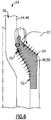
- the outer surfaces 54 of the clamp layers 48, 50 include a plurality of teeth 56 that interact with a traditional "fir-tree" shaped slot 26 of a rotor disk 22 (See Figure 5 ).
- the outer surfaces 54 may include any number of teeth depending on design specific parameters including, but not limited to, the slot design of the rotor disk.
- the clamp 38 is made of a metallic material. However, other materials are contemplated as within the scope of this disclosure.
- the relatively complex shape of the teeth 56 may be machined to closer tolerances, and the clamp 38 can tolerate the high, local stresses associated with interaction of the teeth 56 with the rotor disk 22 by utilizing a strong, durable material such as a metal.
- the clamp layers 48, 50 are glued to the looped portion 36, in one example.
- the first clamp layer 48 is glued to the first arm 44 of the looped portion 36 and the second clamp layer 50 is glued to the second arm 46 of the looped portion.
- the distal ends 42 of the clamp layers 48, 50 are curved in a direction away from the looped portion 36. This curved feature, in combination with the extension of the radial outward end 40 of the plug 34 radially outward from the distal end 42 of the clamp 38, uniformly distributes the compression loads experienced by the attachment portion 27.
- a plurality of compression forces C act upon the attachment portion 27 of the rotor blade 24.
- compression forces C are created by the interaction between of each clamp layer 48, 50 and the first and second arms 44, 46, respectively, at the inner surface 52 of each clamp layer 48, 50.
- the interaction between the rotor disk 22 and the outer surface 54 of each clamp layer 48, 50 creates compression forces C.
- the clamp layers 48, 50 are shaped to communicate the compression forces C through a fillet area 70 of each arm 44, 46 of the looped portion 36. Communicating the compression forces C through the fillet area 70 more securely attaches the rotor blade 24 to the rotor disk 22 and creates favorable stress interaction between the parts. In one example, at least a portion of the compression forces C act upon the first and second arms 44, 46 of the looped portion 36 at a position outboard from the fillet area 70. It should be understood that the actual positioning of the fillet area 70 with respect to the first and second arms 44, 46 of the looped portion 36 and the compression forces C will vary depending upon design specific parameters including, but not limited to, the strength capabilities of the looped portion 36.
Landscapes
- Engineering & Computer Science (AREA)
- Mechanical Engineering (AREA)
- General Engineering & Computer Science (AREA)
- Chemical & Material Sciences (AREA)
- Ceramic Engineering (AREA)
- Turbine Rotor Nozzle Sealing (AREA)
- Structures Of Non-Positive Displacement Pumps (AREA)
Description
- This disclosure relates generally to a rotor blade for a gas turbine engine, and more particularly to an attachment for a composite rotor blade of a gas turbine engine.
- Gas turbine engines, such as turbofan gas turbine engines, typically include a fan section, a compressor section, a combustor section and a turbine section. During operation, air is pressurized in the compressor section and mixed with fuel in the combustor section for generating hot combustion gases. The hot combustion gases flow through the turbine section which extracts energy from the hot combustion gases to power the compressor section and drive the fan section.
- Gas turbine engines typically include a plurality of rotating blades that either add energy to the airflow communicated through the engine or extract energy from the airflow. For example, the turbine section of the gas turbine engine includes a plurality of rotor blades that extract the energy from the hot combustion gases communicated through the turbine section to power the compressor section and the fan section. The rotor blades typically include an airfoil section and a root section that is mounted to a rotating disk. The root section may include a "fir-tree" shape, and the rotating disk may include a slot having a corresponding "fir-tree" shape for receiving the root section.
-
US 2004/0062655 discloses a tailored attachment mechanism for composite airfoils.GB 2262966A FR 1281033 EP 1764480 A1 describes a shim for a turbine engine blade.WO 96/41068 - Gas turbine engine rotor blades made from composite materials are known and can provide significant weight and cooling air savings. Composite rotor blades have a high strength to weight ratio that allows for the design of low weight parts able to withstand extreme temperatures and loading associated with a gas turbine engine.
- One drawback to composite rotor blades is that since the blades are often made of a laminated fiber or filament reinforced composite material, and the rotor disks are typically made from a metallic material, the transfer of forces and loads between the rotor blades and the rotating disk may damage the root section of the rotor blade. In addition, the machining of a traditional "fir-tree" shape on the root section may compromise the strength of a composite rotator blade when using composite materials, such as fabric materials and/or fibers which are layered and glued together with a matrix material.
- Accordingly, it is desirable to provide an improved composite rotor blade that is high in strength and provides adequate attachment to a rotating disk.
- According to a first aspect of the invention, a rotor blade for a gas turbine engine is provided, as claimed in claim 1.
- A gas turbine engine includes a compressor section, a combustor section and a turbine section. A rotor disk is positioned within one of the compressor section and the turbine section and includes a plurality of slots. A plurality of rotor blades are provided, as claimed in claim 1.
- A method for providing a composite rotor blade having an attachment portion including a plug, a looped portion and a clamp for a gas turbine engine includes surrounding the plug with the looped portion, and positioning the clamp such that the clamp only partially surrounds the looped portion, as claimed in
claim 12. The various features and advantages of this disclosure will become apparent to those skilled in the art from the following detailed description. The drawings that accompany the detailed description can be briefly described as follows. -
-
Figure 1 is a cross-sectional view of an example gas turbine engine; -
Figure 2 illustrates a portion of a turbine section of the example gas turbine engine illustrated inFigure 1 ; -
Figure 3 illustrates a schematic view of an example rotor blade having a unique attachment portion; -
Figure 4 illustrates an example clamp of an attachment portion of a rotor blade; -
Figure 5 illustrates a schematic view of another example rotor blade having a unique attachment portion; and -
Figure 6 illustrates the compression forces experienced by an example attachment portion of a rotor blade. -
Figure 1 illustrates an examplegas turbine engine 10 that includes afan section 12, acompressor section 14, acombustor section 16 and aturbine section 18. Thegas turbine engine 10 is defined about an engine centerline axis A about which the various engine sections rotate. As is known, air is drawn into thegas turbine engine 10 by thefan section 12 and flows through thecompressor section 14 to pressurize the airflow. Fuel is mixed with the pressurized air and combusted within thecombustor section 16. The combustion gases are discharged through theturbine section 18 which extracts energy therefrom for powering thecompressor section 14 and afan section 12. Of course, this view is highly schematic. In one example, thegas turbine engine 10 is a turbofan gas turbine engine. It should be understood, however, that the features and illustrations presented within this disclosure are not limited to a turbo fan gas turbine engine. That is, the present disclosure is applicable to any engine architecture. -
Figure 2 schematically illustrates a portion of theturbine section 18 of thegas turbine engine 10. In this example, arotor blade assembly 20 is illustrated. Therotor blade assembly 20 includes arotor disk 22 and a plurality ofrotor blades 24. The plurality ofrotor blades 24 are received withinslots 26 of therotor disk 22. Therotor blades 24 rotate about the engine centerline axis A in a known manner to extract energy from the hot combustion gases communicated through theturbine section 18 for powering thecompressor section 14 and thefan section 12. In one example, therotor blades 24 are composite turbine rotor blades. - The
rotor blades 24 include unique attachment features for mounting therotor blades 24 to therotor disk 22, as is further discussed below. Although the examples and illustrations presented herein with respect to the unique attachment features are discussed in relation to turbine rotor blades, it should be understood that the features and advantages of this disclosure are applicable to various other components of thegas turbine engine 10 such as the fan. -
Figure 3 illustrates arotor blade 24 having anexample attachment portion 27 for connecting therotor blade 24 to arotor disk 22, for example. Therotor blade 24 includes anairfoil 28 that extends in span S between atip 30 and aroot 32. In one example, therotor blade 24 is a composite turbine rotor blade. For example, theairfoil 28 is made of a ceramic matrix composite (CMC) that provides significant weight and cooling air savings to eachrotor blade 24. A person of ordinary skill in the art having the benefit of this disclosure would be able to select an appropriate CMC to construct theairfoil 28. For example, the CMC may include a woven fabric made from Silicone, Carbon and a matrix material. - The
example attachment portion 27 of therotor blade 24 includes aplug 34, a loopedportion 36 and aclamp 38. In one example, theplug 34 is generally teardrop shaped. However,other plug 34 shapes are contemplated as within the scope of this disclosure. Theplug 34 is made of a metallic material, such as a titanium alloy, in one example. In another example, theplug 34 is made from a ceramic material. In yet another example, a CMC is utilized to construct theplug 34. A person of ordinary skill in the art having the benefit of this disclosure would be able to select an appropriate material for theplug 34. - A radial
outward end 40 of theplug 34 extends radially outward of adistal end 42 of theclamp 38. The example configuration distributes the compression loads experienced by theattachment portion 27 of therotor blade 24 over a greater area to reduce the susceptibility of theattachment portion 27 to damages caused by the compression loads.
The loopedportion 36 surrounds theplug 34. In theFig. 3 embodiment, the loopedportion 36 completely encompasses theplug 34. The loopedportion 36 is formed integrally with theroot 32 of therotor blade 24, That is, the loopedportion 36 and theairfoil 28 are a single piece construction. The loopedportion 36 extends radially inward from theroot 32 and includes afirst arm 44 and a second arm 46- Thefirst arm 44 and thesecond arm 46 of the loopedportion 36 extend in opposing directions to surround theplug 34. The loopedportion 36 is made of a CMC, in one example. - The
clamp 38 is positioned on an opposite side of the loopedportion 36 from theplug 34. Theclamp 38 contacts only a portion of the loopedportion 36. That is, theclamp 38 does not entirely surround the loopedportion 36. Theclamp 38 contacts the loopedportion 36 over an area that is less than 360 degrees. - In one example, the
clamp 38 is a 2-piece design and includes afirst clamp layer 48 and asecond clamp layer 50. Thefirst clamp layer 48 and thesecond clamp layer 50 are positioned on opposing sides of the loopedportion 36 of theattachment portion 27. That is, thefirst clamp layer 48 contacts thefirst arm 44 of the loopedportion 36, and thesecond clamp layer 50 contacts thesecond arm 46 of the loopedportion 36. The clamp layers 48, 50 are sandwiched between aninner wall 51 of therotor disk 22 and the loopedportion 36 where therotor blade 24 is received within theslot 26. - Referring to
Figure 4 , each of thefirst clamp layer 48 and thesecond clamp layer 50 include aninner surface 52 and anouter surface 54. Theinner surfaces 52 of the clamp layers 48, 50 are contoured to generally conform to the shape of the loopedportion 36, in this example. Theouter surfaces 54 of the clamp layers 48, 50 are machined with a tooth 56 (or a plurality of teeth 56) to interact with the corresponding shape of theslot 26 of therotor disk 22. In another example, theouter surfaces 54 of the clamp layers 48, 50 include a plurality ofteeth 56 that interact with a traditional "fir-tree" shapedslot 26 of a rotor disk 22 (SeeFigure 5 ). It should be understood that theouter surfaces 54 may include any number of teeth depending on design specific parameters including, but not limited to, the slot design of the rotor disk. - In one example, the
clamp 38 is made of a metallic material. However, other materials are contemplated as within the scope of this disclosure. The relatively complex shape of theteeth 56 may be machined to closer tolerances, and theclamp 38 can tolerate the high, local stresses associated with interaction of theteeth 56 with therotor disk 22 by utilizing a strong, durable material such as a metal. The clamp layers 48, 50 are glued to the loopedportion 36, in one example. For example, thefirst clamp layer 48 is glued to thefirst arm 44 of the loopedportion 36 and thesecond clamp layer 50 is glued to thesecond arm 46 of the looped portion. - The distal ends 42 of the clamp layers 48, 50 are curved in a direction away from the looped
portion 36. This curved feature, in combination with the extension of the radialoutward end 40 of theplug 34 radially outward from thedistal end 42 of theclamp 38, uniformly distributes the compression loads experienced by theattachment portion 27. - Referring to
Figure 6 , a plurality of compression forces C act upon theattachment portion 27 of therotor blade 24. For example, compression forces C are created by the interaction between of eachclamp layer second arms inner surface 52 of eachclamp layer rotor disk 22 and theouter surface 54 of eachclamp layer - The clamp layers 48, 50 are shaped to communicate the compression forces C through a
fillet area 70 of eacharm portion 36. Communicating the compression forces C through thefillet area 70 more securely attaches therotor blade 24 to therotor disk 22 and creates favorable stress interaction between the parts. In one example, at least a portion of the compression forces C act upon the first andsecond arms portion 36 at a position outboard from thefillet area 70. It should be understood that the actual positioning of thefillet area 70 with respect to the first andsecond arms portion 36 and the compression forces C will vary depending upon design specific parameters including, but not limited to, the strength capabilities of the loopedportion 36. - The foregoing disclosure shall be interpreted as illustrative and not in any limiting sense. A worker of ordinary skill in the art would understand that certain modifications would come within the scope of this disclosure. For these reasons, the following claims should be studied to determine the true scope and content of this disclosure.
Claims (15)
- A rotor blade for a gas turbine engine, comprising:an airfoil (28) that extends in span between a tip (30) and a root (32) opposite from said tip (30); whereinsaid root (32) includes a plug (34), a looped portion (36) that surrounds said plug (34) and at least one clamp (38) wherein said at least one clamp (38) contacts only a portion of said looped portion (36), and only partially surrounds said looped portion (36), on an opposite side of said looped portion (36) from said plug (34); characterised in thata distal end (42) of said at least one clamp (38) is curved in a direction away from said looped portion (36).
- The rotor blade as recited in claim 1, wherein said plug (34) is generally teardrop shaped.
- The rotor blade as recited in claim 1 or 2, wherein said looped portion (36) is formed integrally with said root (32).
- The rotor blade as recited in any preceding claim, wherein said looped portion (36) extends radially inwardly from said root (32) and includes a first arm (44) and a second arm (46) that extends on opposed sides of said plug (34) so as to surround said plug (34).
- The rotor blade as recited in any preceding claim, wherein said at least one clamp (38) includes a first clamp layer (48) and a second clamp layer (50), and said first clamp layer (48) contacts said first arm (44) of said looped portion (36) and said second clamp layer (50) contacts said second arm (46) of said looped portion (36).
- The rotor blade as recited in any preceding claim, wherein said at least one clamp (38) includes an inner surface (52) and an outer surface (54), and said outer surface (54) includes at least one tooth (56), for example a plurality of teeth (56).
- The rotor blade as recited in any preceding claim, wherein at least a portion of said plug (34) extends radially outboard of a distal end (42) of said at least one clamp (38).
- A gas turbine engine, comprising:a compressor section (14), a combustor section (16) and a turbine section (18);at least one rotor disk (22) positioned within a least one of said compressor section (14) and said turbine section (18) and including a plurality of slots (26); anda plurality of rotor blades (24) as claimed in claim 1.
- The gas turbine engine as recited in claim 8, wherein said at least one clamp (38) includes a first clamp layer (48) and a second clamp layer (50) each positioned between an inner wall (51) of one of said plurality of slots (26) and said looped portion (36).
- The rotor blade or gas turbine engine as recited in any preceding claim, wherein said rotor blade or plurality of rotor blades (24) are composite turbine blades.
- The rotor blade or gas turbine engine as recited in any preceding claim, wherein said plug (34) is made of at least one of a metal, a ceramic, and a ceramic matrix composite, said looped portion (36) is made of a ceramic matrix composite, and said at least one clamp (38) is made of a metal.
- A method for providing a composite rotor blade having an attachment portion (27) including a plug (34), a looped portion (36) and a clamp (38) for a gas turbine engine (10), comprising the steps of:a) surrounding the plug (34) with the looped portion (36); andb) positioning the clamp (38) such that the clamp (38) only partially surrounds the looped portion (36); characterised in thata distal end (42) of said at least one clamp (38) is curved in a direction away from said looped portion (36).
- The method as recited in claim 12, further comprising:c) positioning the attachment portion (27) within a corresponding slot (26) of a rotor disk (22).
- The method as recited in claim 12 or 13, wherein the clamp (38) includes a first clamp layer (48) and a second clamp layer (50), said looped portion (36) includes a first arm (44) and a second arm (46), and said step b) includes the steps of:gluing the first clamp layer (48) to the first loop arm (44); andgluing the second clamp layer (50) to the second loop arm (46).
- The method as recited in claim 12, 13 or 14, wherein a plurality of compression forces (C) act upon the attachment portion (27), and comprising the steps of:c) positioning at least a portion of the plug (34) radially outboard of a distal end of the clamp (38); andd) communicating the plurality of compression forces (C) through a fillet area (70) of the looped portion (36).
Applications Claiming Priority (1)
| Application Number | Priority Date | Filing Date | Title |
|---|---|---|---|
| US11/969,363 US8206118B2 (en) | 2008-01-04 | 2008-01-04 | Airfoil attachment |
Publications (3)
| Publication Number | Publication Date |
|---|---|
| EP2077376A2 EP2077376A2 (en) | 2009-07-08 |
| EP2077376A3 EP2077376A3 (en) | 2012-04-25 |
| EP2077376B1 true EP2077376B1 (en) | 2017-06-28 |
Family
ID=40336663
Family Applications (1)
| Application Number | Title | Priority Date | Filing Date |
|---|---|---|---|
| EP09250001.6A Active EP2077376B1 (en) | 2008-01-04 | 2009-01-02 | Rotor blade attachment in a gas turbine |
Country Status (2)
| Country | Link |
|---|---|
| US (1) | US8206118B2 (en) |
| EP (1) | EP2077376B1 (en) |
Families Citing this family (35)
| Publication number | Priority date | Publication date | Assignee | Title |
|---|---|---|---|---|
| US8608447B2 (en) * | 2009-02-19 | 2013-12-17 | Rolls-Royce Corporation | Disk for turbine engine |
| EP2322763A1 (en) * | 2009-11-17 | 2011-05-18 | Siemens Aktiengesellschaft | Turbine or compressor blade |
| FR2955143B1 (en) * | 2010-01-12 | 2012-05-11 | Snecma | ARBOR DISK ARRANGEMENT |
| US20110206522A1 (en) * | 2010-02-24 | 2011-08-25 | Ioannis Alvanos | Rotating airfoil fabrication utilizing cmc |
| US9228445B2 (en) * | 2010-12-23 | 2016-01-05 | General Electric Company | Turbine airfoil components containing ceramic-based materials and processes therefor |
| US8821127B1 (en) * | 2011-04-21 | 2014-09-02 | Ken Knecht | Blade lock for compressor |
| FR2974593B1 (en) * | 2011-04-28 | 2015-11-13 | Snecma | TURBINE ENGINE COMPRISING A METAL PROTECTION OF A COMPOSITE PIECE |
| US8291963B1 (en) | 2011-08-03 | 2012-10-23 | United Technologies Corporation | Hybrid core assembly |
| EP2574723A1 (en) * | 2011-09-30 | 2013-04-03 | Alstom Technology Ltd | Retrofitting method for a steam turbine and corresponding device |
| FR2997127A1 (en) | 2012-10-22 | 2014-04-25 | Snecma | HIGH PRESSURE TURBINE BLADES IN CERAMIC MATRIX COMPOSITES |
| US9500083B2 (en) | 2012-11-26 | 2016-11-22 | U.S. Department Of Energy | Apparatus and method to reduce wear and friction between CMC-to-metal attachment and interface |
| US9297265B2 (en) | 2012-12-04 | 2016-03-29 | General Electric Company | Apparatus having engineered surface feature and method to reduce wear and friction between CMC-to-metal attachment and interface |
| WO2014158276A2 (en) * | 2013-03-05 | 2014-10-02 | Rolls-Royce Corporation | Structure and method for providing compliance and sealing between ceramic and metallic structures |
| EP2971559B1 (en) * | 2013-03-13 | 2019-10-23 | United Technologies Corporation | Blade assembly with wear pads, gas turbine engine and method of manufacturing a blade assembly |
| US10487670B2 (en) * | 2013-03-13 | 2019-11-26 | Rolls-Royce Corporation | Gas turbine engine component including a compliant layer |
| EP2971568B1 (en) | 2013-03-15 | 2021-11-03 | Raytheon Technologies Corporation | Flap seal for a fan of a gas turbine engine |
| EP2981676A4 (en) * | 2013-04-02 | 2016-12-07 | United Technologies Corp | Engine component having support with intermediate layer |
| US10519788B2 (en) | 2013-05-29 | 2019-12-31 | General Electric Company | Composite airfoil metal patch |
| JP2015135061A (en) * | 2014-01-16 | 2015-07-27 | 株式会社Ihi | Blade connection part structure and jet engine using the same |
| US9963979B2 (en) | 2014-11-17 | 2018-05-08 | Rolls-Royce North American Technologies Inc. | Composite components for gas turbine engines |
| EP3239469B1 (en) | 2014-11-20 | 2019-01-09 | Rolls-Royce North American Technologies, Inc. | Composite blades for gas turbine engines |
| CA2915234A1 (en) * | 2015-01-13 | 2016-07-13 | Rolls-Royce Corporation | Turbine wheel with clamped blade attachment |
| US10563523B2 (en) | 2015-04-08 | 2020-02-18 | Rolls-Royce Corporation | Method for fabricating a ceramic matrix composite rotor blade |
| US10227880B2 (en) | 2015-11-10 | 2019-03-12 | General Electric Company | Turbine blade attachment mechanism |
| US10753368B2 (en) | 2016-08-23 | 2020-08-25 | Raytheon Technologies Corporation | Multi-piece non-linear airfoil |
| RU2686644C1 (en) * | 2018-04-18 | 2019-04-29 | Виктор Степанович Ермоленко | Composite compressor blade |
| US10677075B2 (en) | 2018-05-04 | 2020-06-09 | General Electric Company | Composite airfoil assembly for an interdigitated rotor |
| US10941665B2 (en) | 2018-05-04 | 2021-03-09 | General Electric Company | Composite airfoil assembly for an interdigitated rotor |
| US11028714B2 (en) * | 2018-07-16 | 2021-06-08 | Raytheon Technologies Corporation | Fan platform wedge seal |
| JP7143197B2 (en) * | 2018-11-29 | 2022-09-28 | 株式会社荏原製作所 | Blades, turbines, and methods of manufacturing blades |
| US11286796B2 (en) | 2019-05-08 | 2022-03-29 | Raytheon Technologies Corporation | Cooled attachment sleeve for a ceramic matrix composite rotor blade |
| US20210115796A1 (en) * | 2019-10-18 | 2021-04-22 | United Technologies Corporation | Airfoil component with trailing end margin and cutback |
| US11492733B2 (en) * | 2020-02-21 | 2022-11-08 | Raytheon Technologies Corporation | Weave control grid |
| US11156110B1 (en) | 2020-08-04 | 2021-10-26 | General Electric Company | Rotor assembly for a turbine section of a gas turbine engine |
| US11655719B2 (en) | 2021-04-16 | 2023-05-23 | General Electric Company | Airfoil assembly |
Family Cites Families (27)
| Publication number | Priority date | Publication date | Assignee | Title |
|---|---|---|---|---|
| US2656146A (en) * | 1948-04-08 | 1953-10-20 | Curtiss Wright Corp | Turbine blade construction |
| GB709636A (en) * | 1951-05-09 | 1954-06-02 | Rolls Royce | Improvements in or relating to compressor and turbine bladed rotors |
| FR1281033A (en) * | 1961-02-15 | 1962-01-08 | Daimler Benz Ag | Assembly of ceramic moving blades on machines with centrifugal rotors axially traversed by currents, in particular on gas turbines |
| US3752600A (en) * | 1971-12-09 | 1973-08-14 | United Aircraft Corp | Root pads for composite blades |
| US4037990A (en) * | 1976-06-01 | 1977-07-26 | General Electric Company | Composite turbomachinery rotor |
| US4152488A (en) | 1977-05-03 | 1979-05-01 | United Technologies Corporation | Gas turbine blade tip alloy and composite |
| US4417854A (en) * | 1980-03-21 | 1983-11-29 | Rockwell International Corporation | Compliant interface for ceramic turbine blades |
| US5346367A (en) | 1984-12-21 | 1994-09-13 | United Technologies Corporation | Advanced composite rotor blade |
| US4725200A (en) * | 1987-02-24 | 1988-02-16 | Westinghouse Electric Corp. | Apparatus and method for reducing relative motion between blade and rotor in steam turbine |
| US4921405A (en) | 1988-11-10 | 1990-05-01 | Allied-Signal Inc. | Dual structure turbine blade |
| US5118257A (en) | 1990-05-25 | 1992-06-02 | Sundstrand Corporation | Boot attachment for composite turbine blade, turbine blade and method of making turbine blade |
| US5340280A (en) | 1991-09-30 | 1994-08-23 | General Electric Company | Dovetail attachment for composite blade and method for making |
| US5222297A (en) | 1991-10-18 | 1993-06-29 | United Technologies Corporation | Composite blade manufacture |
| FR2685732B1 (en) * | 1991-12-31 | 1994-02-25 | Snecma | BLADE OF TURBOMACHINE IN COMPOSITE MATERIAL. |
| US5240375A (en) * | 1992-01-10 | 1993-08-31 | General Electric Company | Wear protection system for turbine engine rotor and blade |
| US5240377A (en) | 1992-02-25 | 1993-08-31 | Williams International Corporation | Composite fan blade |
| US5378110A (en) | 1992-09-14 | 1995-01-03 | United Technologies Corporation | Composite compressor rotor with removable airfoils |
| WO1996041068A1 (en) * | 1995-06-07 | 1996-12-19 | National Research Council Of Canada | Anti-fretting barrier |
| DE19724523C1 (en) * | 1997-06-11 | 1998-06-04 | Haweka Gmbh | Quick clamping nut for securing vehicle rim to balancing machine |
| US6004101A (en) | 1998-08-17 | 1999-12-21 | General Electric Company | Reinforced aluminum fan blade |
| US6290466B1 (en) | 1999-09-17 | 2001-09-18 | General Electric Company | Composite blade root attachment |
| US6607358B2 (en) | 2002-01-08 | 2003-08-19 | General Electric Company | Multi-component hybrid turbine blade |
| US6758653B2 (en) | 2002-09-09 | 2004-07-06 | Siemens Westinghouse Power Corporation | Ceramic matrix composite component for a gas turbine engine |
| US7300255B2 (en) * | 2002-09-27 | 2007-11-27 | Florida Turbine Technologies, Inc. | Laminated turbomachine airfoil with jacket and method of making the airfoil |
| US6857856B2 (en) | 2002-09-27 | 2005-02-22 | Florida Turbine Technologies, Inc. | Tailored attachment mechanism for composite airfoils |
| FR2890684B1 (en) * | 2005-09-15 | 2007-12-07 | Snecma | CLINKING FOR TURBOREACTOR BLADE |
| US7452189B2 (en) | 2006-05-03 | 2008-11-18 | United Technologies Corporation | Ceramic matrix composite turbine engine vane |
-
2008
- 2008-01-04 US US11/969,363 patent/US8206118B2/en active Active
-
2009
- 2009-01-02 EP EP09250001.6A patent/EP2077376B1/en active Active
Non-Patent Citations (1)
| Title |
|---|
| None * |
Also Published As
| Publication number | Publication date |
|---|---|
| EP2077376A2 (en) | 2009-07-08 |
| US8206118B2 (en) | 2012-06-26 |
| EP2077376A3 (en) | 2012-04-25 |
| US20100284816A1 (en) | 2010-11-11 |
Similar Documents
| Publication | Publication Date | Title |
|---|---|---|
| EP2077376B1 (en) | Rotor blade attachment in a gas turbine | |
| US8944773B2 (en) | Rotor blade with bonded cover | |
| EP2348192B1 (en) | Fan airfoil sheath | |
| EP2305954B1 (en) | Internally damped blade | |
| EP2599959B1 (en) | Ceramic matrix composite airfoil structure with trailing edge support for a gas turbine engine | |
| EP2752557B1 (en) | Platformless turbine blade | |
| EP2423440B1 (en) | Root region of a blade for a gas turbine engine | |
| JP6240672B2 (en) | Ceramic center body and manufacturing method | |
| US20140212284A1 (en) | Hybrid turbine nozzle | |
| US20150345296A1 (en) | Turbine bucket assembly and turbine system | |
| US9045990B2 (en) | Integrated ceramic matrix composite rotor disk geometry for a gas turbine engine | |
| EP2570611B1 (en) | Ceramic matrix composite airfoil for a gas turbine engine and corresponding method of forming | |
| JP2016000994A (en) | Turbine bucket assembly and turbine system | |
| EP3865663B1 (en) | Extended root region and platform over-wrap for a blade of a gas turbine engine | |
| EP2636846A1 (en) | Fabricated turbine airfoil | |
| US11105209B2 (en) | Turbine blade tip shroud | |
| US11692444B2 (en) | Gas turbine engine rotor blade having a root section with composite and metallic portions | |
| EP3287601A1 (en) | Multi-piece non-linear fan blade |
Legal Events
| Date | Code | Title | Description |
|---|---|---|---|
| PUAI | Public reference made under article 153(3) epc to a published international application that has entered the european phase |
Free format text: ORIGINAL CODE: 0009012 |
|
| AK | Designated contracting states |
Kind code of ref document: A2 Designated state(s): AT BE BG CH CY CZ DE DK EE ES FI FR GB GR HR HU IE IS IT LI LT LU LV MC MK MT NL NO PL PT RO SE SI SK TR |
|
| AX | Request for extension of the european patent |
Extension state: AL BA RS |
|
| PUAL | Search report despatched |
Free format text: ORIGINAL CODE: 0009013 |
|
| AK | Designated contracting states |
Kind code of ref document: A3 Designated state(s): AT BE BG CH CY CZ DE DK EE ES FI FR GB GR HR HU IE IS IT LI LT LU LV MC MK MT NL NO PL PT RO SE SI SK TR |
|
| AX | Request for extension of the european patent |
Extension state: AL BA RS |
|
| RIC1 | Information provided on ipc code assigned before grant |
Ipc: F01D 5/30 20060101AFI20120316BHEP |
|
| 17P | Request for examination filed |
Effective date: 20121025 |
|
| AKX | Designation fees paid |
Designated state(s): DE GB |
|
| 17Q | First examination report despatched |
Effective date: 20160223 |
|
| RAP1 | Party data changed (applicant data changed or rights of an application transferred) |
Owner name: UNITED TECHNOLOGIES CORPORATION |
|
| GRAP | Despatch of communication of intention to grant a patent |
Free format text: ORIGINAL CODE: EPIDOSNIGR1 |
|
| INTG | Intention to grant announced |
Effective date: 20170228 |
|
| GRAS | Grant fee paid |
Free format text: ORIGINAL CODE: EPIDOSNIGR3 |
|
| GRAA | (expected) grant |
Free format text: ORIGINAL CODE: 0009210 |
|
| AK | Designated contracting states |
Kind code of ref document: B1 Designated state(s): DE GB |
|
| REG | Reference to a national code |
Ref country code: GB Ref legal event code: FG4D |
|
| REG | Reference to a national code |
Ref country code: DE Ref legal event code: R096 Ref document number: 602009046832 Country of ref document: DE |
|
| REG | Reference to a national code |
Ref country code: DE Ref legal event code: R097 Ref document number: 602009046832 Country of ref document: DE |
|
| PLBE | No opposition filed within time limit |
Free format text: ORIGINAL CODE: 0009261 |
|
| STAA | Information on the status of an ep patent application or granted ep patent |
Free format text: STATUS: NO OPPOSITION FILED WITHIN TIME LIMIT |
|
| 26N | No opposition filed |
Effective date: 20180329 |
|
| REG | Reference to a national code |
Ref country code: DE Ref legal event code: R081 Ref document number: 602009046832 Country of ref document: DE Owner name: RAYTHEON TECHNOLOGIES CORPORATION (N.D.GES.D.S, US Free format text: FORMER OWNER: UNITED TECHNOLOGIES CORPORATION, FARMINGTON, CONN., US |
|
| P01 | Opt-out of the competence of the unified patent court (upc) registered |
Effective date: 20230519 |
|
| PGFP | Annual fee paid to national office [announced via postgrant information from national office to epo] |
Ref country code: GB Payment date: 20231219 Year of fee payment: 16 |
|
| PGFP | Annual fee paid to national office [announced via postgrant information from national office to epo] |
Ref country code: DE Payment date: 20231219 Year of fee payment: 16 |