EP3865663B1 - Extended root region and platform over-wrap for a blade of a gas turbine engine - Google Patents
Extended root region and platform over-wrap for a blade of a gas turbine engine Download PDFInfo
- Publication number
- EP3865663B1 EP3865663B1 EP21155748.3A EP21155748A EP3865663B1 EP 3865663 B1 EP3865663 B1 EP 3865663B1 EP 21155748 A EP21155748 A EP 21155748A EP 3865663 B1 EP3865663 B1 EP 3865663B1
- Authority
- EP
- European Patent Office
- Prior art keywords
- platform
- blade
- wrap
- recited
- platform over
- Prior art date
- Legal status (The legal status is an assumption and is not a legal conclusion. Google has not performed a legal analysis and makes no representation as to the accuracy of the status listed.)
- Active
Links
- 230000006835 compression Effects 0.000 claims description 20
- 238000007906 compression Methods 0.000 claims description 20
- 239000000919 ceramic Substances 0.000 claims description 14
- 239000011159 matrix material Substances 0.000 claims description 13
- 238000000034 method Methods 0.000 claims description 11
- XUIMIQQOPSSXEZ-UHFFFAOYSA-N Silicon Chemical compound [Si] XUIMIQQOPSSXEZ-UHFFFAOYSA-N 0.000 claims description 4
- 238000004519 manufacturing process Methods 0.000 claims description 4
- 229910052710 silicon Inorganic materials 0.000 claims description 4
- 239000010703 silicon Substances 0.000 claims description 4
- 239000007921 spray Substances 0.000 claims description 2
- 239000011153 ceramic matrix composite Substances 0.000 description 14
- 239000007789 gas Substances 0.000 description 12
- 239000002131 composite material Substances 0.000 description 11
- 239000000463 material Substances 0.000 description 5
- HBMJWWWQQXIZIP-UHFFFAOYSA-N silicon carbide Chemical compound [Si+]#[C-] HBMJWWWQQXIZIP-UHFFFAOYSA-N 0.000 description 5
- 229910010271 silicon carbide Inorganic materials 0.000 description 5
- PXHVJJICTQNCMI-UHFFFAOYSA-N Nickel Chemical compound [Ni] PXHVJJICTQNCMI-UHFFFAOYSA-N 0.000 description 4
- 239000004744 fabric Substances 0.000 description 4
- 239000000835 fiber Substances 0.000 description 4
- PNEYBMLMFCGWSK-UHFFFAOYSA-N aluminium oxide Inorganic materials [O-2].[O-2].[O-2].[Al+3].[Al+3] PNEYBMLMFCGWSK-UHFFFAOYSA-N 0.000 description 3
- 239000002243 precursor Substances 0.000 description 3
- 229920000049 Carbon (fiber) Polymers 0.000 description 2
- 230000008901 benefit Effects 0.000 description 2
- 230000005540 biological transmission Effects 0.000 description 2
- 239000000567 combustion gas Substances 0.000 description 2
- 238000010276 construction Methods 0.000 description 2
- 229910052593 corundum Inorganic materials 0.000 description 2
- 238000000151 deposition Methods 0.000 description 2
- 239000000446 fuel Substances 0.000 description 2
- 238000003754 machining Methods 0.000 description 2
- 229910052759 nickel Inorganic materials 0.000 description 2
- 230000007704 transition Effects 0.000 description 2
- 229910001845 yogo sapphire Inorganic materials 0.000 description 2
- OKTJSMMVPCPJKN-UHFFFAOYSA-N Carbon Chemical compound [C] OKTJSMMVPCPJKN-UHFFFAOYSA-N 0.000 description 1
- 239000004215 Carbon black (E152) Substances 0.000 description 1
- 229920002134 Carboxymethyl cellulose Polymers 0.000 description 1
- 239000004593 Epoxy Substances 0.000 description 1
- 239000000654 additive Substances 0.000 description 1
- 230000000996 additive effect Effects 0.000 description 1
- 229910045601 alloy Inorganic materials 0.000 description 1
- 239000000956 alloy Substances 0.000 description 1
- 238000005452 bending Methods 0.000 description 1
- 229910052799 carbon Inorganic materials 0.000 description 1
- 239000004917 carbon fiber Substances 0.000 description 1
- 239000011204 carbon fibre-reinforced silicon carbide Substances 0.000 description 1
- 235000010948 carboxy methyl cellulose Nutrition 0.000 description 1
- 229920006184 cellulose methylcellulose Polymers 0.000 description 1
- 238000012710 chemistry, manufacturing and control Methods 0.000 description 1
- 238000004891 communication Methods 0.000 description 1
- 229930195733 hydrocarbon Natural products 0.000 description 1
- 150000002430 hydrocarbons Chemical class 0.000 description 1
- 229910000816 inconels 718 Inorganic materials 0.000 description 1
- 239000007788 liquid Substances 0.000 description 1
- 238000005259 measurement Methods 0.000 description 1
- 230000008018 melting Effects 0.000 description 1
- 238000002844 melting Methods 0.000 description 1
- 239000002184 metal Substances 0.000 description 1
- 229910052751 metal Inorganic materials 0.000 description 1
- 239000007769 metal material Substances 0.000 description 1
- VNWKTOKETHGBQD-UHFFFAOYSA-N methane Chemical compound C VNWKTOKETHGBQD-UHFFFAOYSA-N 0.000 description 1
- 239000000203 mixture Substances 0.000 description 1
- 238000012986 modification Methods 0.000 description 1
- 230000004048 modification Effects 0.000 description 1
- 239000003607 modifier Substances 0.000 description 1
- 229920003257 polycarbosilane Polymers 0.000 description 1
- 229920000642 polymer Polymers 0.000 description 1
- 239000000843 powder Substances 0.000 description 1
- 230000008569 process Effects 0.000 description 1
- 238000000197 pyrolysis Methods 0.000 description 1
- 230000009467 reduction Effects 0.000 description 1
- 239000011347 resin Substances 0.000 description 1
- 229920005989 resin Polymers 0.000 description 1
- 230000035939 shock Effects 0.000 description 1
- 238000005245 sintering Methods 0.000 description 1
- 239000007787 solid Substances 0.000 description 1
- 238000007711 solidification Methods 0.000 description 1
- 230000008023 solidification Effects 0.000 description 1
- 229910000601 superalloy Inorganic materials 0.000 description 1
- 238000011282 treatment Methods 0.000 description 1
- 229910001247 waspaloy Inorganic materials 0.000 description 1
Images


Classifications
-
- F—MECHANICAL ENGINEERING; LIGHTING; HEATING; WEAPONS; BLASTING
- F01—MACHINES OR ENGINES IN GENERAL; ENGINE PLANTS IN GENERAL; STEAM ENGINES
- F01D—NON-POSITIVE DISPLACEMENT MACHINES OR ENGINES, e.g. STEAM TURBINES
- F01D5/00—Blades; Blade-carrying members; Heating, heat-insulating, cooling or antivibration means on the blades or the members
- F01D5/12—Blades
- F01D5/14—Form or construction
- F01D5/147—Construction, i.e. structural features, e.g. of weight-saving hollow blades
-
- F—MECHANICAL ENGINEERING; LIGHTING; HEATING; WEAPONS; BLASTING
- F01—MACHINES OR ENGINES IN GENERAL; ENGINE PLANTS IN GENERAL; STEAM ENGINES
- F01D—NON-POSITIVE DISPLACEMENT MACHINES OR ENGINES, e.g. STEAM TURBINES
- F01D5/00—Blades; Blade-carrying members; Heating, heat-insulating, cooling or antivibration means on the blades or the members
- F01D5/30—Fixing blades to rotors; Blade roots ; Blade spacers
- F01D5/3084—Fixing blades to rotors; Blade roots ; Blade spacers the blades being made of ceramics
-
- F—MECHANICAL ENGINEERING; LIGHTING; HEATING; WEAPONS; BLASTING
- F01—MACHINES OR ENGINES IN GENERAL; ENGINE PLANTS IN GENERAL; STEAM ENGINES
- F01D—NON-POSITIVE DISPLACEMENT MACHINES OR ENGINES, e.g. STEAM TURBINES
- F01D5/00—Blades; Blade-carrying members; Heating, heat-insulating, cooling or antivibration means on the blades or the members
- F01D5/12—Blades
- F01D5/28—Selecting particular materials; Particular measures relating thereto; Measures against erosion or corrosion
- F01D5/282—Selecting composite materials, e.g. blades with reinforcing filaments
-
- F—MECHANICAL ENGINEERING; LIGHTING; HEATING; WEAPONS; BLASTING
- F01—MACHINES OR ENGINES IN GENERAL; ENGINE PLANTS IN GENERAL; STEAM ENGINES
- F01D—NON-POSITIVE DISPLACEMENT MACHINES OR ENGINES, e.g. STEAM TURBINES
- F01D5/00—Blades; Blade-carrying members; Heating, heat-insulating, cooling or antivibration means on the blades or the members
- F01D5/12—Blades
- F01D5/28—Selecting particular materials; Particular measures relating thereto; Measures against erosion or corrosion
- F01D5/284—Selection of ceramic materials
-
- F—MECHANICAL ENGINEERING; LIGHTING; HEATING; WEAPONS; BLASTING
- F01—MACHINES OR ENGINES IN GENERAL; ENGINE PLANTS IN GENERAL; STEAM ENGINES
- F01D—NON-POSITIVE DISPLACEMENT MACHINES OR ENGINES, e.g. STEAM TURBINES
- F01D5/00—Blades; Blade-carrying members; Heating, heat-insulating, cooling or antivibration means on the blades or the members
- F01D5/30—Fixing blades to rotors; Blade roots ; Blade spacers
- F01D5/3007—Fixing blades to rotors; Blade roots ; Blade spacers of axial insertion type
-
- F—MECHANICAL ENGINEERING; LIGHTING; HEATING; WEAPONS; BLASTING
- F01—MACHINES OR ENGINES IN GENERAL; ENGINE PLANTS IN GENERAL; STEAM ENGINES
- F01D—NON-POSITIVE DISPLACEMENT MACHINES OR ENGINES, e.g. STEAM TURBINES
- F01D5/00—Blades; Blade-carrying members; Heating, heat-insulating, cooling or antivibration means on the blades or the members
- F01D5/30—Fixing blades to rotors; Blade roots ; Blade spacers
- F01D5/3092—Protective layers between blade root and rotor disc surfaces, e.g. anti-friction layers
-
- F—MECHANICAL ENGINEERING; LIGHTING; HEATING; WEAPONS; BLASTING
- F05—INDEXING SCHEMES RELATING TO ENGINES OR PUMPS IN VARIOUS SUBCLASSES OF CLASSES F01-F04
- F05D—INDEXING SCHEME FOR ASPECTS RELATING TO NON-POSITIVE-DISPLACEMENT MACHINES OR ENGINES, GAS-TURBINES OR JET-PROPULSION PLANTS
- F05D2220/00—Application
- F05D2220/30—Application in turbines
- F05D2220/32—Application in turbines in gas turbines
-
- F—MECHANICAL ENGINEERING; LIGHTING; HEATING; WEAPONS; BLASTING
- F05—INDEXING SCHEMES RELATING TO ENGINES OR PUMPS IN VARIOUS SUBCLASSES OF CLASSES F01-F04
- F05D—INDEXING SCHEME FOR ASPECTS RELATING TO NON-POSITIVE-DISPLACEMENT MACHINES OR ENGINES, GAS-TURBINES OR JET-PROPULSION PLANTS
- F05D2230/00—Manufacture
- F05D2230/60—Assembly methods
-
- F—MECHANICAL ENGINEERING; LIGHTING; HEATING; WEAPONS; BLASTING
- F05—INDEXING SCHEMES RELATING TO ENGINES OR PUMPS IN VARIOUS SUBCLASSES OF CLASSES F01-F04
- F05D—INDEXING SCHEME FOR ASPECTS RELATING TO NON-POSITIVE-DISPLACEMENT MACHINES OR ENGINES, GAS-TURBINES OR JET-PROPULSION PLANTS
- F05D2240/00—Components
- F05D2240/80—Platforms for stationary or moving blades
-
- F—MECHANICAL ENGINEERING; LIGHTING; HEATING; WEAPONS; BLASTING
- F05—INDEXING SCHEMES RELATING TO ENGINES OR PUMPS IN VARIOUS SUBCLASSES OF CLASSES F01-F04
- F05D—INDEXING SCHEME FOR ASPECTS RELATING TO NON-POSITIVE-DISPLACEMENT MACHINES OR ENGINES, GAS-TURBINES OR JET-PROPULSION PLANTS
- F05D2300/00—Materials; Properties thereof
- F05D2300/60—Properties or characteristics given to material by treatment or manufacturing
- F05D2300/601—Fabrics
- F05D2300/6012—Woven fabrics
-
- F—MECHANICAL ENGINEERING; LIGHTING; HEATING; WEAPONS; BLASTING
- F05—INDEXING SCHEMES RELATING TO ENGINES OR PUMPS IN VARIOUS SUBCLASSES OF CLASSES F01-F04
- F05D—INDEXING SCHEME FOR ASPECTS RELATING TO NON-POSITIVE-DISPLACEMENT MACHINES OR ENGINES, GAS-TURBINES OR JET-PROPULSION PLANTS
- F05D2300/00—Materials; Properties thereof
- F05D2300/60—Properties or characteristics given to material by treatment or manufacturing
- F05D2300/603—Composites; e.g. fibre-reinforced
- F05D2300/6033—Ceramic matrix composites [CMC]
-
- Y—GENERAL TAGGING OF NEW TECHNOLOGICAL DEVELOPMENTS; GENERAL TAGGING OF CROSS-SECTIONAL TECHNOLOGIES SPANNING OVER SEVERAL SECTIONS OF THE IPC; TECHNICAL SUBJECTS COVERED BY FORMER USPC CROSS-REFERENCE ART COLLECTIONS [XRACs] AND DIGESTS
- Y02—TECHNOLOGIES OR APPLICATIONS FOR MITIGATION OR ADAPTATION AGAINST CLIMATE CHANGE
- Y02T—CLIMATE CHANGE MITIGATION TECHNOLOGIES RELATED TO TRANSPORTATION
- Y02T50/00—Aeronautics or air transport
- Y02T50/60—Efficient propulsion technologies, e.g. for aircraft
Definitions
- This invention relates generally to a gas turbine engine blade and more specifically to the root region of composite blades.
- Gas turbine engines such as those that power modern commercial and military aircraft, generally include a compressor to pressurize an airflow, a combustor to burn a hydrocarbon fuel in the presence of the pressurized air, and a turbine to extract energy from the resultant combustion gases.
- Air is compressed in various fan and compressor stages by rotor blades which cooperate with stator vanes.
- Fan air provides bypass propulsion thrust while compressor air is mixed with fuel and ignited for generation of hot combustion gases from which energy is extracted by a turbine section which powers the compressor and fan sections.
- the turbine section often includes blades formed from ceramic matrix composites ("CMC") which may have relatively low interlaminar properties such that attachment regions between a platform region and airfoil region may be subject to significant interlaminar stress. Integrating the platform may be a challenge in transmitting the centrifugal load into the root region. Loss of bond has been shown analytically to cause distortions which will further increase the platform loads, leading to a cascading structural load increase.
- CMC ceramic matrix composites
- US 2019/330990 discloses a turbine blade with an attachment-supported platform for composite material construction.
- WO 2015/080781 discloses a ply architecture for integral platform and damper retaining features in CMC turbine blades.
- CH 707728 discloses systems and a method for a composite blade with a fillet transition.
- a rotor blade for a gas turbine engine is provided in accordance with claim 1.
- the inner ply layer group at least partially defines an airfoil.
- the inner ply layer group, the platform, and the platform over-wrap defines a flared surface of the root region of the rotor blade.
- the inner ply layer group and the platform over-wrap are manufactured of a ceramic matrix material.
- the inner ply layer group, the platform, and the platform over-wrap comprise a ceramic matrix material.
- the platform over-wrap defines an attachment surface at which a disk interfaces.
- an attachment surface defines a zone of compression through the platform over-wrap and into said inner ply layer group.
- the zone of compression is defined along a line that is oriented at 30-50 degrees with respect to the blade root centerline.
- the blade includes a point on a centerline of the blade is defined by a line perpendicular to a point in the zone of compression, the base of the root region defined below the point.
- the point on the zone of compression is a central point on the line that defines the zone of compression.
- the point on the zone of compression is a most inboard point on the line that defines the zone of compression.
- the base is perpendicular to a centerline of the blade.
- an outer surface of the platform over-wrap below an attachment surface is parallel to the centerline.
- the blade includes an outer surface of the platform over-wrap below an attachment surface which forms an inward angle toward the centerline of up to about 10 degrees.
- a method of manufacturing a rotor blade of a gas turbine engine is provided in accordance with claim 13.
- the method includes forming an attachment surface with the platform over-wrap.
- the method includes applying a silicon plasma spray to form a machinable layer on the attachment surface.
- the method includes forming a flared surface with the platform, the inner ply layer group, and the platform over-wrap.
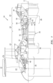
- FIG. 1 schematically illustrates a gas turbine engine 20.
- the gas turbine engine 20 as disclosed herein is a two spool turbofan that generally incorporates a fan section 22, a compressor section 24, a combustor section 26, and a turbine section 28.
- the fan section 22 drives air along a bypass flowpath while the compressor section 24 drives air along a high temperature core flowpath for compression and communication into the combustor section 26, then expansion through the turbine section 28.
- FIG. 1 schematically illustrates a gas turbine engine 20.
- the gas turbine engine 20 as disclosed herein is
- the engine 20 generally includes a low spool 30 and a high spool 32 mounted for rotation around an engine central longitudinal axis A relative to an engine case structure 36 via several bearings 38.
- the low spool 30 generally includes an inner shaft 40 that interconnects a fan 42, a low pressure compressor (“LPC”) 44 and a low pressure turbine (“LPT”) 46.
- the inner shaft 40 drives the fan 42 directly or through a geared architecture 48 to drive the fan 42 at a lower speed than the low spool 30.
- An exemplary reduction transmission is an epicyclic transmission, namely a planetary or star gear system.
- the high spool 32 includes an outer shaft 50 that interconnects a high pressure compressor (“HPC”) 52 and high pressure turbine (“HPT”) 54.
- a combustor 56 is arranged between the HPC 52 and the HPT 54.
- a rotor assembly 60 such as a turbine rotor assembly includes an array of blades 84 (one shown) circumferentially disposed around a disk 86.
- the disk 86 may be subtractive or additive manufactured of nickel-based super alloys that operate in high temperature environments, such as, for example, environments typically encountered by aerospace and gas turbine engine hot section components.
- the nickel-based alloy may be Inconel 718, Waspaloy, IN-100,.
- Each blade 84 includes a root region 88, a platform 90 and an airfoil 92.
- the platform 90 separates a gas path side inclusive of the airfoil 92 and a non-gas path side inclusive of the root region 88.
- the airfoil 92 defines a blade chord between a leading edge 98, which may include various forward and/or aft sweep configurations, and a trailing edge 100.
- a first sidewall 102 that may be convex to define a suction side, and a second sidewall 104 that may be concave to define a pressure side are joined at the leading edge 98 and at the axially spaced trailing edge 100.
- the tip 96 extends between the sidewalls 102, 104 opposite the platform 90.
- Each blade root region 88 is received within one blade slot 94 in a rim 87 of the disk 86 such that the airfoil 92 extends therefrom and the platform 90 at least partially protects the rim 87.
- a blade 84 is disclosed in detail, however other composite components which require attachment such as the root region 88 to include but not be limited to vanes, blade outer air seals, struts, etc., will also benefit herefrom.
- Each blade 84 may be manufactured of a composite material such as ceramic matrix composite (CMC) or an organic matrix composite (OMC) material.
- the composite materials typically include prepreg ceramic plys that include prepreg ceramic fiber tows. The tows in each ply are arranged adjacent to one another in a planar orientation such that each ply has a unidirectional orientation.
- CMC materials include, but are not limited to, carbon-fiber-reinforced carbon (C/C), carbon-fiber-reinforced silicon carbide (C/SiC), silicon-carbide-fiber-reinforced silicon carbide (SiC/SiC), alumina-fiber-reinforced alumina (Al 2 O 3 / Al 2 O 3 ), organic matrix composite (e.g. carbon fiber epoxy) or combinations thereof.
- the CMC may have increased elongation, fracture toughness, thermal shock, dynamic load capability, and anisotropic properties as compared to a monolithic ceramic structure.
- CMC materials may utilize tackified ceramic fabric/fibers whereby the fibers have not been infiltrated with matrix material, 3D weave architectures of dry fabrics, and others. Although CMCs are primarily discussed in the disclosed embodiment, other such non-metallic materials may also be utilized to form the component.
- Manufacture of the blade 84 typically includes laying up pre-impregnated composite fibers within a matrix material (prepreg) to form the geometry of the part (pre-form), autoclaving and burning out the pre-form, infiltrating the burned-out pre-form with the melting matrix material, then final machining and treatments of the pre-form.
- Infiltrating the pre-form may include depositing the ceramic matrix out of a gas mixture, pyrolyzing a pre-ceramic polymer, chemically reacting elements, sintering, generally in the temperature range of 1700 - 3000F (925-1650C), or electrophoretically depositing a ceramic powder.
- the composites may be located over a metal spar and form only the outer surface of the airfoil.
- the blade 84 may be loaded primarily in one direction (radial pull) that have been created in ceramic matrix composite (CMC) or organic matrix composite (OMC) material with relatively direct ply orientations having minimal bending.
- the root region 88 may include a flared region 105 below a neck 106.
- the flared region 105 may alternatively at least partially form a teardrop, fir-tree, or other shape of the root region 88 to resist the radial pull during engine operation.
- a method 200 of manufacturing the root region 88 initially includes assembling the platform 90 around an inner ply layer group 122 ( FIG. 4 ) as shown in step 202 that at least partially forms the flared region 105 that extends to a base 110 which is the innermost end of the blade 84.
- the inner ply layer group 122 may continue radially outward with respect to the engine axis to at least partially form the airfoil 92 ( FIG. 2 ).
- the platform 90 is assembled as a multiple of platform sections 90A, 90B ( FIG. 4 ) that surround an outermost ply 122-1 of the inner ply layer group 122.
- the platform 90 also at least partially forms the lay-up of the flared region 105. Although illustrated as formed in two section that are assembled together, any number of sections may be utilized.
- the platform sections 90A, 90B may be formed as an integral woven ply layup that is later solidified, pre-ceramics which are later solidified, or preformed sections which have already been solidified.
- the platform sections 90A, 90B at least partially form the base 110 of the root region 88.
- the platform sections 90A, 90B are then wrapped with a platform over-wrap 112 ( FIG. 3 , step 204).
- the platform over-wrap 112 may be formed as a continuous band that extends to the base 110 of the root region.
- the platform over-wrap 112 is a woven, tape, or knitted ceramic fabric such as silicon carbide fabric, silicon carbide-carbon fabric or other such material that may be pre-impregnated with a matrix precursor such as a polycarbosilane pre-ceramic matrix precursor or other liquid resin.
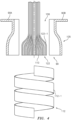
- the platform over-wrap 112 may also be a tubular three-dimensional weave ( FIG. 5 ) which fits over the platform sections 90A, 90B.
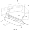
- An outermost ply 112-1 of the platform over-wrap 112 forms an attachment surface 130 and extends to the base 110 of the root region 88. Extension of the platform over-wrap 112 over the full attachment surface 130 ( FIG. 6 and 7 ) to the base 110 significantly increases the structural load path and facilitates control of the stresses in the platform 90 even if the platform 90 is not fully bonded, to the inner ply layer group 122.
- the inner ply layer group 122, the platform sections 90A, 90B and the platform over-wrap 112 are solidified ( FIG. 3 , step 206).
- the solidifying process may be performed via a pyrolysis tool, such as a mold that is located within a furnace.
- the heat from the furnace converts the matrix precursors to a solid ceramic matrix composite that solidifies and bonds the layers together to form the root region 88.
- the heat from the furnace may also provide for final solidification of the platform sections 90A, 90B if initially assembled as pre-ceramics or other "green" level components.
- the outermost ply 112-1 of the platform over-wrap 112 may be silicon plasma sprayed to form a machinable layer 108 ( FIG. 3 , step 208) at least over the attachment surface 130.
- the machinable layer 108 permits high tolerance final machining ( FIG. 3 , step 210) of the attachment surface 130.
- the root region 88 sandwiches the platform 90 between the platform over-wrap 112 and the inner ply layer group 122 such that high interlaminar tensile/shear (ILT/ILS) regions of the root region 88 are contained within regions of compressive stress in the root region 88 to increase the total allowable ILT/ILS stress.
- ILT/ILS interlaminar tensile/shear
- the inner ply layer group 122 includes an outermost ply 122-1 to which the platform sections 90A, 90B are assembled.
- the assembled platform 90 is then wrapped with the platform over-wrap 112 to define the root region 88.
- Applicant has determined that the root region 88 below the attachment surface 130 is particularly important to blade strength. Analysis has shown that fully wrapping the platform 90 with the platform over-wrap 112 to extend to the base 110, permits the root region 88 to operate without radial support from the blade neck region 106. Thus, extending the root region 88 inward toward the engine axis, and maintaining a full, uninterrupted platform over-wrap 112 to the base 110, significantly increases the structural capability of the root region 88.
- the outermost ply 112-1 of the platform over-wrap 112 may include the machinable layer 108 over the length of the attachment surface 130.
- an outer surface 132 of the platform over-wrap 112 inboard of the attachment surface 130 may be parallel to the centerline of the blade.
- the outer surface 132 of the platform over-wrap 112 inboard of the attachment surface 130 may form an inward (toward the blade root centerline) angle of up to about 10 degrees. That is, the outer surface 132 of the platform over-wrap 112 may taper inward toward the blade centerline by up to about 10 degrees for relatively smaller engines with a lesser number of blades.
- the attachment surface 130 of the flared region 105 is represented along line AB.
- the attachment surface 130 is the surface of the flared region 105 upon which a disk attachment tooth interfaces of the blade slot 94 in a rim 87 of the disk 86 is in contact ( FIG. 2 ).
- the attachment surface 130 along line AB may be considered a "zone of compression” that extends through the platform over-wrap 112, the platform 90, and into the inner ply layer group 122 when the engine is operating and the blade 84 is subjected to centrifugal forces.
- the "zone of compression” is represented herein via a typical bolted joint methodology to calculate the spring rate of the stack in compression.
- the outermost ply 122-1 of the inner ply layer group 122 remains generally parallel to the blade root centerline from point D then transitions into the flared region 105 such that the plys radially inboard of line CE remain in compression during engine operation.
- a 45 degree angle defined from line CF defines line CD to locate point D and thus the outermost ply 112-1 which is to be parallel to the blade centerline.
- the attachment surface 130 may be outwardly oriented about 30-50 degrees with respect to the blade root centerline.
- a midpoint of line AB is represented herein by point C.
- Line CF is perpendicular to line AB and is extended perpendicular from line AB to intersect the blade root centerline at point F.
- Line BG is perpendicular to line AB and parallel to line CF. Line BG extends perpendicular from line AB to intersect the blade root centerline at point G. Point G defines the most inboard point of the zone of compression.
- the base 110 should be located radially inboard of at least point F (illustrated in phantom), and alternatively inboard of point G, along the blade centerline. That is, the base 110 is the bottom most surface of the root region 88, the platform 90 and the platform over-wrap 112.
Description
- This invention relates generally to a gas turbine engine blade and more specifically to the root region of composite blades.
- Gas turbine engines, such as those that power modern commercial and military aircraft, generally include a compressor to pressurize an airflow, a combustor to burn a hydrocarbon fuel in the presence of the pressurized air, and a turbine to extract energy from the resultant combustion gases. Air is compressed in various fan and compressor stages by rotor blades which cooperate with stator vanes. Fan air provides bypass propulsion thrust while compressor air is mixed with fuel and ignited for generation of hot combustion gases from which energy is extracted by a turbine section which powers the compressor and fan sections.
- The turbine section often includes blades formed from ceramic matrix composites ("CMC") which may have relatively low interlaminar properties such that attachment regions between a platform region and airfoil region may be subject to significant interlaminar stress. Integrating the platform may be a challenge in transmitting the centrifugal load into the root region. Loss of bond has been shown analytically to cause distortions which will further increase the platform loads, leading to a cascading structural load increase.
-
US 2019/330990 discloses a turbine blade with an attachment-supported platform for composite material construction. -
US 2018/119549 discloses a turbine blade with three-dimensional CMC construction elements. -
WO 2015/080781 discloses a ply architecture for integral platform and damper retaining features in CMC turbine blades. -
CH 707728 - According to an aspect of the present invention, a rotor blade for a gas turbine engine is provided in accordance with claim 1.
- Optionally, the inner ply layer group at least partially defines an airfoil.
- Optionally, the inner ply layer group, the platform, and the platform over-wrap defines a flared surface of the root region of the rotor blade.
- Optionally, the inner ply layer group and the platform over-wrap are manufactured of a ceramic matrix material.
- Optionally, the inner ply layer group, the platform, and the platform over-wrap comprise a ceramic matrix material.
- Optionally, the platform over-wrap defines an attachment surface at which a disk interfaces.
- Optionally, an attachment surface defines a zone of compression through the platform over-wrap and into said inner ply layer group.
- Optionally, the zone of compression is defined along a line that is oriented at 30-50 degrees with respect to the blade root centerline.
- Optionally, the blade includes a point on a centerline of the blade is defined by a line perpendicular to a point in the zone of compression, the base of the root region defined below the point.
- Optionally, the point on the zone of compression is a central point on the line that defines the zone of compression.
- Optionally, the point on the zone of compression is a most inboard point on the line that defines the zone of compression.
- Optionally, the base is perpendicular to a centerline of the blade.
- Optionally, an outer surface of the platform over-wrap below an attachment surface is parallel to the centerline.
- Optionally, the blade includes an outer surface of the platform over-wrap below an attachment surface which forms an inward angle toward the centerline of up to about 10 degrees.
- According to another aspect of the present invention, a method of manufacturing a rotor blade of a gas turbine engine is provided in accordance with claim 13.
- Optionally, the method includes forming an attachment surface with the platform over-wrap.
- Optionally, the method includes applying a silicon plasma spray to form a machinable layer on the attachment surface.
- Optionally, the method includes forming a flared surface with the platform, the inner ply layer group, and the platform over-wrap.
The foregoing features and elements may be combined in various combinations without exclusivity, unless expressly indicated otherwise. These features and elements as well as the operation thereof will become more apparent in light of the following description and the accompanying drawings. It should be appreciated; however, the following description and drawings are intended to be exemplary in nature and non-limiting. - Various features will become apparent to those skilled in the art from the following detailed description of the disclosed non-limiting embodiment. The drawings that accompany the detailed description can be briefly described as follows:
-
FIG. 1 is a schematic cross-section of an example gas turbine engine architecture. -
FIG. 2 is an exploded view of a rotor assembly with a single representative ceramic matrix composite turbine blade. -
FIG. 3 is a method of assembling a blade with an extended root region and platform wrap according to one embodiment. -
FIG. 4 is an exploded view of the extended root region and platform wrap. -
FIG. 5 is a perspective view of a tubular platform over-wrap according to one embodiment. -
FIG. 6 is a perspective view of a root for a blade according to one embodiment. -
FIG. 7 is a sectional view of the blade root along line 6-6 inFIG. 5 . -
FIG. 1 schematically illustrates agas turbine engine 20. Thegas turbine engine 20 as disclosed herein is a two spool turbofan that generally incorporates afan section 22, acompressor section 24, acombustor section 26, and aturbine section 28. Thefan section 22 drives air along a bypass flowpath while thecompressor section 24 drives air along a high temperature core flowpath for compression and communication into thecombustor section 26, then expansion through theturbine section 28. Although depicted as a high bypass gas turbofan engine architecture in the disclosed non-limiting embodiment, it should be appreciated that the concepts described herein are not limited only thereto. - The
engine 20 generally includes alow spool 30 and ahigh spool 32 mounted for rotation around an engine central longitudinal axis A relative to anengine case structure 36 viaseveral bearings 38. Thelow spool 30 generally includes aninner shaft 40 that interconnects afan 42, a low pressure compressor ("LPC") 44 and a low pressure turbine ("LPT") 46. Theinner shaft 40 drives thefan 42 directly or through a gearedarchitecture 48 to drive thefan 42 at a lower speed than thelow spool 30. An exemplary reduction transmission is an epicyclic transmission, namely a planetary or star gear system. Thehigh spool 32 includes anouter shaft 50 that interconnects a high pressure compressor ("HPC") 52 and high pressure turbine ("HPT") 54. Acombustor 56 is arranged between the HPC 52 and the HPT 54. - With reference to
FIG. 2 , arotor assembly 60 such as a turbine rotor assembly includes an array of blades 84 (one shown) circumferentially disposed around adisk 86. Thedisk 86 may be subtractive or additive manufactured of nickel-based super alloys that operate in high temperature environments, such as, for example, environments typically encountered by aerospace and gas turbine engine hot section components. In some embodiments, the nickel-based alloy may be Inconel 718, Waspaloy, IN-100,. - Each
blade 84 includes aroot region 88, aplatform 90 and anairfoil 92. Theplatform 90 separates a gas path side inclusive of theairfoil 92 and a non-gas path side inclusive of theroot region 88. Although theplatform 90 is illustrated as integral in the illustrated embodiment, other geometries in which theplatform 90 is a separate component may alternatively be utilized. Theairfoil 92 defines a blade chord between a leadingedge 98, which may include various forward and/or aft sweep configurations, and atrailing edge 100. Afirst sidewall 102 that may be convex to define a suction side, and asecond sidewall 104 that may be concave to define a pressure side are joined at the leadingedge 98 and at the axially spacedtrailing edge 100. Thetip 96 extends between thesidewalls platform 90. - Each
blade root region 88 is received within oneblade slot 94 in arim 87 of thedisk 86 such that theairfoil 92 extends therefrom and theplatform 90 at least partially protects therim 87. In the illustrated embodiment, ablade 84 is disclosed in detail, however other composite components which require attachment such as theroot region 88 to include but not be limited to vanes, blade outer air seals, struts, etc., will also benefit herefrom. - Each
blade 84 may be manufactured of a composite material such as ceramic matrix composite (CMC) or an organic matrix composite (OMC) material. The composite materials typically include prepreg ceramic plys that include prepreg ceramic fiber tows. The tows in each ply are arranged adjacent to one another in a planar orientation such that each ply has a unidirectional orientation. Examples of CMC materials include, but are not limited to, carbon-fiber-reinforced carbon (C/C), carbon-fiber-reinforced silicon carbide (C/SiC), silicon-carbide-fiber-reinforced silicon carbide (SiC/SiC), alumina-fiber-reinforced alumina (Al2O3/ Al2O3), organic matrix composite (e.g. carbon fiber epoxy) or combinations thereof. The CMC may have increased elongation, fracture toughness, thermal shock, dynamic load capability, and anisotropic properties as compared to a monolithic ceramic structure. Other CMC materials may utilize tackified ceramic fabric/fibers whereby the fibers have not been infiltrated with matrix material, 3D weave architectures of dry fabrics, and others. Although CMCs are primarily discussed in the disclosed embodiment, other such non-metallic materials may also be utilized to form the component. - Manufacture of the
blade 84 typically includes laying up pre-impregnated composite fibers within a matrix material (prepreg) to form the geometry of the part (pre-form), autoclaving and burning out the pre-form, infiltrating the burned-out pre-form with the melting matrix material, then final machining and treatments of the pre-form. Infiltrating the pre-form may include depositing the ceramic matrix out of a gas mixture, pyrolyzing a pre-ceramic polymer, chemically reacting elements, sintering, generally in the temperature range of 1700 - 3000F (925-1650C), or electrophoretically depositing a ceramic powder. With respect to airfoils, the composites may be located over a metal spar and form only the outer surface of the airfoil. - The
blade 84 may be loaded primarily in one direction (radial pull) that have been created in ceramic matrix composite (CMC) or organic matrix composite (OMC) material with relatively direct ply orientations having minimal bending. Theroot region 88 may include a flaredregion 105 below aneck 106. The flaredregion 105 may alternatively at least partially form a teardrop, fir-tree, or other shape of theroot region 88 to resist the radial pull during engine operation. - With reference to
FIG. 3 , amethod 200 of manufacturing theroot region 88 initially includes assembling theplatform 90 around an inner ply layer group 122 (FIG. 4 ) as shown instep 202 that at least partially forms the flaredregion 105 that extends to a base 110 which is the innermost end of theblade 84. The innerply layer group 122 may continue radially outward with respect to the engine axis to at least partially form the airfoil 92 (FIG. 2 ). - The
platform 90 is assembled as a multiple ofplatform sections FIG. 4 ) that surround an outermost ply 122-1 of the innerply layer group 122. Theplatform 90 also at least partially forms the lay-up of the flaredregion 105. Although illustrated as formed in two section that are assembled together, any number of sections may be utilized. Theplatform sections platform sections base 110 of theroot region 88. - Once assembled to the inner
ply layer group 122, theplatform sections FIG. 3 , step 204). Theplatform over-wrap 112 may be formed as a continuous band that extends to thebase 110 of the root region. In one example, theplatform over-wrap 112 is a woven, tape, or knitted ceramic fabric such as silicon carbide fabric, silicon carbide-carbon fabric or other such material that may be pre-impregnated with a matrix precursor such as a polycarbosilane pre-ceramic matrix precursor or other liquid resin. Alternatively, theplatform over-wrap 112 may also be a tubular three-dimensional weave (FIG. 5 ) which fits over theplatform sections - An outermost ply 112-1 of the
platform over-wrap 112 forms anattachment surface 130 and extends to thebase 110 of theroot region 88. Extension of theplatform over-wrap 112 over the full attachment surface 130 (FIG. 6 and7 ) to the base 110 significantly increases the structural load path and facilitates control of the stresses in theplatform 90 even if theplatform 90 is not fully bonded, to the innerply layer group 122. - Next, the inner
ply layer group 122, theplatform sections platform over-wrap 112 are solidified (FIG. 3 , step 206). The solidifying process may be performed via a pyrolysis tool, such as a mold that is located within a furnace. The heat from the furnace converts the matrix precursors to a solid ceramic matrix composite that solidifies and bonds the layers together to form theroot region 88. The heat from the furnace may also provide for final solidification of theplatform sections - Next, the outermost ply 112-1 of the
platform over-wrap 112 may be silicon plasma sprayed to form a machinable layer 108 (FIG. 3 , step 208) at least over theattachment surface 130. Themachinable layer 108 permits high tolerance final machining (FIG. 3 , step 210) of theattachment surface 130. - With reference to
FIG. 7 , theroot region 88 sandwiches theplatform 90 between theplatform over-wrap 112 and the innerply layer group 122 such that high interlaminar tensile/shear (ILT/ILS) regions of theroot region 88 are contained within regions of compressive stress in theroot region 88 to increase the total allowable ILT/ILS stress. - The inner
ply layer group 122 includes an outermost ply 122-1 to which theplatform sections platform 90 is then wrapped with theplatform over-wrap 112 to define theroot region 88. Applicant has determined that theroot region 88 below theattachment surface 130 is particularly important to blade strength. Analysis has shown that fully wrapping theplatform 90 with theplatform over-wrap 112 to extend to thebase 110, permits theroot region 88 to operate without radial support from theblade neck region 106. Thus, extending theroot region 88 inward toward the engine axis, and maintaining a full,uninterrupted platform over-wrap 112 to thebase 110, significantly increases the structural capability of theroot region 88. - In one embodiment, the outermost ply 112-1 of the
platform over-wrap 112 may include themachinable layer 108 over the length of theattachment surface 130. In this embodiment, anouter surface 132 of theplatform over-wrap 112 inboard of theattachment surface 130 may be parallel to the centerline of the blade. Alternatively, theouter surface 132 of theplatform over-wrap 112 inboard of theattachment surface 130 may form an inward (toward the blade root centerline) angle of up to about 10 degrees. That is, theouter surface 132 of theplatform over-wrap 112 may taper inward toward the blade centerline by up to about 10 degrees for relatively smaller engines with a lesser number of blades. - The
attachment surface 130 of the flaredregion 105 is represented along line AB. Theattachment surface 130 is the surface of the flaredregion 105 upon which a disk attachment tooth interfaces of theblade slot 94 in arim 87 of thedisk 86 is in contact (FIG. 2 ). Theattachment surface 130 along line AB may be considered a "zone of compression" that extends through theplatform over-wrap 112, theplatform 90, and into the innerply layer group 122 when the engine is operating and theblade 84 is subjected to centrifugal forces. The "zone of compression" is represented herein via a typical bolted joint methodology to calculate the spring rate of the stack in compression. The outermost ply 122-1 of the innerply layer group 122 remains generally parallel to the blade root centerline from point D then transitions into the flaredregion 105 such that the plys radially inboard of line CE remain in compression during engine operation. Per the bolted joint methodology, a 45 degree angle defined from line CF defines line CD to locate point D and thus the outermost ply 112-1 which is to be parallel to the blade centerline. - In this embodiment, the
attachment surface 130 may be outwardly oriented about 30-50 degrees with respect to the blade root centerline. - A midpoint of line AB is represented herein by point C. Line CF is perpendicular to line AB and is extended perpendicular from line AB to intersect the blade root centerline at point F. Line BG is perpendicular to line AB and parallel to line CF. Line BG extends perpendicular from line AB to intersect the blade root centerline at point G. Point G defines the most inboard point of the zone of compression.
- Applicant has determined that the base 110 should be located radially inboard of at least point F (illustrated in phantom), and alternatively inboard of point G, along the blade centerline. That is, the
base 110 is the bottom most surface of theroot region 88, theplatform 90 and theplatform over-wrap 112. - The use of the terms "a", "an", "the", and similar references in the context of description (especially in the context of the following claims) are to be construed to cover both the singular and the plural, unless otherwise indicated herein or specifically contradicted by context. The modifier "about" used in connection with a quantity is inclusive of the stated value and has the meaning dictated by the context (e.g., it includes the degree of error associated with measurement of the particular quantity). All ranges disclosed herein are inclusive of the endpoints, and the endpoints are independently combinable with each other.
- Although the different non-limiting embodiments have specific illustrated components, the embodiments of this invention are not limited to those particular combinations. It is possible to use some of the components or features from any of the non-limiting embodiments in combination with features or components from any of the other non-limiting embodiments.
- It should be appreciated that like reference numerals identify corresponding or similar elements throughout the several drawings. It should also be appreciated that although a particular component arrangement is disclosed in the illustrated embodiment, other arrangements will benefit herefrom.
- The foregoing invention is exemplary rather than defined by the limitations within. Various non-limiting embodiments are disclosed herein, however, one of ordinary skill in the art would recognize that various modifications and variations in light of the above teachings will fall within the scope of the appended claims. It is therefore to be understood that within the scope of the appended claims, the disclosure may be practiced other than as specifically described. For that reason, the appended claims should be studied to determine true scope and content.
Claims (15)
- A rotor blade (84) for a gas turbine engine (20), comprising:an inner ply layer group (122) that at least partially defines a base (110) of a root region (88);a platform (90) defined by at least two platform sections (90A, 90B) that surround the inner ply layer group (122) and at least partially define the base (110); anda platform over-wrap (112) around the platform (90), the platform over-wrap (112) at least partially defines the base (110).
- The blade (84) as recited in claim 1, wherein the inner ply layer group (122) at least partially defines an airfoil (92).
- The blade (84) as recited in claim 1 or 2, wherein the inner ply layer group (122), the platform (90), and the platform over-wrap (112) defines a flared surface (105) of the root region (88) of the rotor blade (84).
- The blade (84) as recited in claim 1, 2, or 3, wherein the inner ply layer group (122), the platform over-wrap (112) and, optionally, the platform (90) are manufactured of a ceramic matrix material.
- The blade (84) as recited in any preceding claim, wherein the platform over-wrap (112) defines an attachment surface (130) at which a disk (86) interfaces.
- The blade (84) as recited in claim 5, wherein the attachment surface (130) defines a zone of compression through the platform over-wrap (112) and into said inner ply layer group (122), wherein the zone of compression is optionally defined along a line (AB) that is oriented at 30-50 degrees with respect to the blade root centerline.
- The blade (84) as recited in claim 6, wherein a point on a centerline of the blade (84) is defined by a line perpendicular to a point in the zone of compression, the base (110) of the root region (88) defined below the point.
- The blade (84) as recited in claim 7, wherein the point on the zone of compression is a central point on the line that defines the zone of compression.
- The blade (84) as recited in claim 7, wherein the point on the zone of compressions is a most inboard point on the line that defines the zone of compression.
- The blade (84) as recited in any of claims 5 to 9, wherein an outer surface (132) of the platform over-wrap (112) below the attachment surface (130) is parallel to the centerline.
- The blade (84) as recited in claim 10, wherein the outer surface (132) of the platform over-wrap (112) below the attachment surface (130) forms an inward angle toward the centerline of up to about 10 degrees.
- The blade (84) as recited in any preceding claim, wherein the base (110) is perpendicular to a centerline of the blade (84).
- A method of manufacturing a rotor blade (84) of a gas turbine engine (20), comprising:assembling a platform (90), defined by at least two platform sections (90A, 90B), around an inner ply layer group (122), the platform sections (90A, 90B) and the inner ply layer group (122) at least partially forming a base (110) of a root region (88); andwrapping the platform (90) with a platform over-wrap (112), the platform over-wrap (112) at least partially forming the base (110).
- The method as recited in claim 13, further comprising:
forming the platform over-wrap (112) as a continuous band; and optionally forming an attachment surface (130) with the platform over-wrap (112) and applying a silicon plasma spray to form a machinable layer on the attachment surface (130). - The method as recited in claim 14, further comprising forming a flared surface (105) with the platform (90), the inner ply layer group (122), and the platform over-wrap (112).
Applications Claiming Priority (1)
| Application Number | Priority Date | Filing Date | Title |
|---|---|---|---|
| US16/784,431 US11377969B2 (en) | 2020-02-07 | 2020-02-07 | Extended root region and platform over-wrap for a blade of a gas turbine engine |
Publications (2)
| Publication Number | Publication Date |
|---|---|
| EP3865663A1 EP3865663A1 (en) | 2021-08-18 |
| EP3865663B1 true EP3865663B1 (en) | 2023-06-28 |
Family
ID=74561754
Family Applications (1)
| Application Number | Title | Priority Date | Filing Date |
|---|---|---|---|
| EP21155748.3A Active EP3865663B1 (en) | 2020-02-07 | 2021-02-08 | Extended root region and platform over-wrap for a blade of a gas turbine engine |
Country Status (2)
| Country | Link |
|---|---|
| US (1) | US11377969B2 (en) |
| EP (1) | EP3865663B1 (en) |
Family Cites Families (23)
| Publication number | Priority date | Publication date | Assignee | Title |
|---|---|---|---|---|
| US4343593A (en) * | 1980-01-25 | 1982-08-10 | The United States Of America As Represented By The Secretary Of The Air Force | Composite blade for turbofan engine fan |
| US4453890A (en) * | 1981-06-18 | 1984-06-12 | General Electric Company | Blading system for a gas turbine engine |
| US6132175A (en) * | 1997-05-29 | 2000-10-17 | Alliedsignal, Inc. | Compliant sleeve for ceramic turbine blades |
| FR2950286B1 (en) * | 2009-09-24 | 2013-08-09 | Snecma | PROCESS FOR MANUFACTURING A TURBOMACHINE BLADE OF COMPOSITE MATERIAL |
| US8794925B2 (en) * | 2010-08-24 | 2014-08-05 | United Technologies Corporation | Root region of a blade for a gas turbine engine |
| US8777583B2 (en) | 2010-12-27 | 2014-07-15 | General Electric Company | Turbine airfoil components containing ceramic-based materials and processes therefor |
| US20130011271A1 (en) * | 2011-07-05 | 2013-01-10 | United Technologies Corporation | Ceramic matrix composite components |
| US10287897B2 (en) * | 2011-09-08 | 2019-05-14 | General Electric Company | Turbine rotor blade assembly and method of assembling same |
| US9611746B2 (en) * | 2012-03-26 | 2017-04-04 | United Technologies Corporation | Blade wedge attachment |
| US10132170B2 (en) | 2013-03-15 | 2018-11-20 | General Electric Company | Systems and method for a composite blade with fillet transition |
| WO2015080781A2 (en) | 2013-09-11 | 2015-06-04 | General Electric Company | Ply architecture for integral platform and damper retaining features in cmc turbine blades |
| US9963979B2 (en) * | 2014-11-17 | 2018-05-08 | Rolls-Royce North American Technologies Inc. | Composite components for gas turbine engines |
| EP3026216B1 (en) | 2014-11-20 | 2017-07-12 | Rolls-Royce North American Technologies, Inc. | Composite blades for gas turbine engines |
| US10253639B2 (en) * | 2015-02-05 | 2019-04-09 | Rolls-Royce North American Technologies, Inc. | Ceramic matrix composite gas turbine engine blade |
| EP3199505A1 (en) * | 2016-01-29 | 2017-08-02 | Rolls-Royce Corporation | Plasma spray physical vapor deposition deposited environmental barrier coating including a layer that includes a rare earth silicate and closed porosity |
| US10443409B2 (en) | 2016-10-28 | 2019-10-15 | Rolls-Royce North American Technologies Inc. | Turbine blade with ceramic matrix composite material construction |
| US10577939B2 (en) * | 2016-11-01 | 2020-03-03 | Rolls-Royce Corporation | Turbine blade with three-dimensional CMC construction elements |
| US20180171806A1 (en) | 2016-12-21 | 2018-06-21 | Rolls-Royce North American Technologies, Inc. | Three-dimensionally woven ceramic matrix composite turbine blade |
| US10605100B2 (en) * | 2017-05-24 | 2020-03-31 | General Electric Company | Ceramic matrix composite (CMC) turbine blade assembly, dovetail sleeve, and method of mounting CMC turbine blade |
| US11014857B2 (en) * | 2017-09-20 | 2021-05-25 | General Electric Company | Contact interface for a composite component and methods of fabrication |
| US11261744B2 (en) * | 2019-06-14 | 2022-03-01 | Raytheon Technologies Corporation | Ceramic matrix composite rotor blade attachment |
| US11143040B2 (en) * | 2019-10-02 | 2021-10-12 | Raytheon Technologies Corporation | Ceramic matrix composite rotor blade attachment and method of manufacture therefor |
| US11441430B2 (en) * | 2020-02-07 | 2022-09-13 | Raytheon Technologies Corporation | Airfoil with buffer layer to absorb thermal mismatch |
-
2020
- 2020-02-07 US US16/784,431 patent/US11377969B2/en active Active
-
2021
- 2021-02-08 EP EP21155748.3A patent/EP3865663B1/en active Active
Also Published As
| Publication number | Publication date |
|---|---|
| US20210246791A1 (en) | 2021-08-12 |
| EP3865663A1 (en) | 2021-08-18 |
| US11377969B2 (en) | 2022-07-05 |
Similar Documents
| Publication | Publication Date | Title |
|---|---|---|
| US11149569B2 (en) | Flow path assembly with airfoils inserted through flow path boundary | |
| EP3459732A1 (en) | Ceramic matrix composite articles | |
| US9308708B2 (en) | Process for producing ceramic composite components | |
| US9708918B2 (en) | Hollow-blade turbine vane made from composite material, turbine or compressor including a nozzle or guide vane assembly formed by such blades, and turbomachine comprising same | |
| US11384651B2 (en) | Methods and features for positioning a flow path inner boundary within a flow path assembly | |
| EP3574189A1 (en) | Unitary flowpath structure | |
| US11739663B2 (en) | CTE matching hanger support for CMC structures | |
| CN110439626B (en) | Composite airfoil assembly for interdigitated rotors | |
| CN114704335A (en) | Composite airfoil assembly having separate airfoils, inner band and outer band | |
| EP3617450B1 (en) | Cmc component including directionally controllable cmc insert and method of fabrication | |
| US11732597B2 (en) | Double box composite seal assembly with insert for gas turbine engine | |
| CN110439625B (en) | Composite airfoil assembly for interdigitated rotors | |
| EP3800326B1 (en) | Ceramic matrix composite rotor blade attachment and method of manufacture therefor | |
| EP3835553B1 (en) | Non-metallic side plate seal assembly for a gas turbine engine | |
| EP3517282B1 (en) | Composite component having t or l-joints and method for forming same | |
| EP3865663B1 (en) | Extended root region and platform over-wrap for a blade of a gas turbine engine | |
| EP3287601B1 (en) | Multi-piece non-linear fan blade | |
| US20200072061A1 (en) | Turbine Blade Tip Shroud | |
| US20190170013A1 (en) | Discontinuous Molded Tape Wear Interface for Composite Components | |
| EP3751103B1 (en) | Ceramic matrix composite rotor blade attachment | |
| US11280202B2 (en) | Balanced composite root region for a blade of a gas turbine engine |
Legal Events
| Date | Code | Title | Description |
|---|---|---|---|
| PUAI | Public reference made under article 153(3) epc to a published international application that has entered the european phase |
Free format text: ORIGINAL CODE: 0009012 |
|
| STAA | Information on the status of an ep patent application or granted ep patent |
Free format text: STATUS: THE APPLICATION HAS BEEN PUBLISHED |
|
| AK | Designated contracting states |
Kind code of ref document: A1 Designated state(s): AL AT BE BG CH CY CZ DE DK EE ES FI FR GB GR HR HU IE IS IT LI LT LU LV MC MK MT NL NO PL PT RO RS SE SI SK SM TR |
|
| STAA | Information on the status of an ep patent application or granted ep patent |
Free format text: STATUS: REQUEST FOR EXAMINATION WAS MADE |
|
| 17P | Request for examination filed |
Effective date: 20220218 |
|
| RBV | Designated contracting states (corrected) |
Designated state(s): AL AT BE BG CH CY CZ DE DK EE ES FI FR GB GR HR HU IE IS IT LI LT LU LV MC MK MT NL NO PL PT RO RS SE SI SK SM TR |
|
| GRAP | Despatch of communication of intention to grant a patent |
Free format text: ORIGINAL CODE: EPIDOSNIGR1 |
|
| STAA | Information on the status of an ep patent application or granted ep patent |
Free format text: STATUS: GRANT OF PATENT IS INTENDED |
|
| INTG | Intention to grant announced |
Effective date: 20230110 |
|
| RIN1 | Information on inventor provided before grant (corrected) |
Inventor name: MCCAFFREY, MICHAEL G. |
|
| GRAS | Grant fee paid |
Free format text: ORIGINAL CODE: EPIDOSNIGR3 |
|
| GRAA | (expected) grant |
Free format text: ORIGINAL CODE: 0009210 |
|
| STAA | Information on the status of an ep patent application or granted ep patent |
Free format text: STATUS: THE PATENT HAS BEEN GRANTED |
|
| AK | Designated contracting states |
Kind code of ref document: B1 Designated state(s): AL AT BE BG CH CY CZ DE DK EE ES FI FR GB GR HR HU IE IS IT LI LT LU LV MC MK MT NL NO PL PT RO RS SE SI SK SM TR |
|
| REG | Reference to a national code |
Ref country code: CH Ref legal event code: EP |
|
| REG | Reference to a national code |
Ref country code: AT Ref legal event code: REF Ref document number: 1582844 Country of ref document: AT Kind code of ref document: T Effective date: 20230715 |
|
| REG | Reference to a national code |
Ref country code: IE Ref legal event code: FG4D |
|
| REG | Reference to a national code |
Ref country code: DE Ref legal event code: R096 Ref document number: 602021003066 Country of ref document: DE |
|
| REG | Reference to a national code |
Ref country code: LT Ref legal event code: MG9D |
|
| PG25 | Lapsed in a contracting state [announced via postgrant information from national office to epo] |
Ref country code: SE Free format text: LAPSE BECAUSE OF FAILURE TO SUBMIT A TRANSLATION OF THE DESCRIPTION OR TO PAY THE FEE WITHIN THE PRESCRIBED TIME-LIMIT Effective date: 20230628 Ref country code: NO Free format text: LAPSE BECAUSE OF FAILURE TO SUBMIT A TRANSLATION OF THE DESCRIPTION OR TO PAY THE FEE WITHIN THE PRESCRIBED TIME-LIMIT Effective date: 20230928 |
|
| RAP4 | Party data changed (patent owner data changed or rights of a patent transferred) |
Owner name: RTX CORPORATION |
|
| REG | Reference to a national code |
Ref country code: NL Ref legal event code: MP Effective date: 20230628 |
|
| REG | Reference to a national code |
Ref country code: AT Ref legal event code: MK05 Ref document number: 1582844 Country of ref document: AT Kind code of ref document: T Effective date: 20230628 |
|
| PG25 | Lapsed in a contracting state [announced via postgrant information from national office to epo] |
Ref country code: RS Free format text: LAPSE BECAUSE OF FAILURE TO SUBMIT A TRANSLATION OF THE DESCRIPTION OR TO PAY THE FEE WITHIN THE PRESCRIBED TIME-LIMIT Effective date: 20230628 Ref country code: NL Free format text: LAPSE BECAUSE OF FAILURE TO SUBMIT A TRANSLATION OF THE DESCRIPTION OR TO PAY THE FEE WITHIN THE PRESCRIBED TIME-LIMIT Effective date: 20230628 Ref country code: LV Free format text: LAPSE BECAUSE OF FAILURE TO SUBMIT A TRANSLATION OF THE DESCRIPTION OR TO PAY THE FEE WITHIN THE PRESCRIBED TIME-LIMIT Effective date: 20230628 Ref country code: LT Free format text: LAPSE BECAUSE OF FAILURE TO SUBMIT A TRANSLATION OF THE DESCRIPTION OR TO PAY THE FEE WITHIN THE PRESCRIBED TIME-LIMIT Effective date: 20230628 Ref country code: HR Free format text: LAPSE BECAUSE OF FAILURE TO SUBMIT A TRANSLATION OF THE DESCRIPTION OR TO PAY THE FEE WITHIN THE PRESCRIBED TIME-LIMIT Effective date: 20230628 Ref country code: GR Free format text: LAPSE BECAUSE OF FAILURE TO SUBMIT A TRANSLATION OF THE DESCRIPTION OR TO PAY THE FEE WITHIN THE PRESCRIBED TIME-LIMIT Effective date: 20230929 |
|
| PG25 | Lapsed in a contracting state [announced via postgrant information from national office to epo] |
Ref country code: FI Free format text: LAPSE BECAUSE OF FAILURE TO SUBMIT A TRANSLATION OF THE DESCRIPTION OR TO PAY THE FEE WITHIN THE PRESCRIBED TIME-LIMIT Effective date: 20230628 |
|
| PG25 | Lapsed in a contracting state [announced via postgrant information from national office to epo] |
Ref country code: SK Free format text: LAPSE BECAUSE OF FAILURE TO SUBMIT A TRANSLATION OF THE DESCRIPTION OR TO PAY THE FEE WITHIN THE PRESCRIBED TIME-LIMIT Effective date: 20230628 |
|
| PG25 | Lapsed in a contracting state [announced via postgrant information from national office to epo] |
Ref country code: ES Free format text: LAPSE BECAUSE OF FAILURE TO SUBMIT A TRANSLATION OF THE DESCRIPTION OR TO PAY THE FEE WITHIN THE PRESCRIBED TIME-LIMIT Effective date: 20230628 |
|
| PG25 | Lapsed in a contracting state [announced via postgrant information from national office to epo] |
Ref country code: IS Free format text: LAPSE BECAUSE OF FAILURE TO SUBMIT A TRANSLATION OF THE DESCRIPTION OR TO PAY THE FEE WITHIN THE PRESCRIBED TIME-LIMIT Effective date: 20231028 |
|
| PG25 | Lapsed in a contracting state [announced via postgrant information from national office to epo] |
Ref country code: SM Free format text: LAPSE BECAUSE OF FAILURE TO SUBMIT A TRANSLATION OF THE DESCRIPTION OR TO PAY THE FEE WITHIN THE PRESCRIBED TIME-LIMIT Effective date: 20230628 Ref country code: SK Free format text: LAPSE BECAUSE OF FAILURE TO SUBMIT A TRANSLATION OF THE DESCRIPTION OR TO PAY THE FEE WITHIN THE PRESCRIBED TIME-LIMIT Effective date: 20230628 Ref country code: RO Free format text: LAPSE BECAUSE OF FAILURE TO SUBMIT A TRANSLATION OF THE DESCRIPTION OR TO PAY THE FEE WITHIN THE PRESCRIBED TIME-LIMIT Effective date: 20230628 Ref country code: PT Free format text: LAPSE BECAUSE OF FAILURE TO SUBMIT A TRANSLATION OF THE DESCRIPTION OR TO PAY THE FEE WITHIN THE PRESCRIBED TIME-LIMIT Effective date: 20231030 Ref country code: IS Free format text: LAPSE BECAUSE OF FAILURE TO SUBMIT A TRANSLATION OF THE DESCRIPTION OR TO PAY THE FEE WITHIN THE PRESCRIBED TIME-LIMIT Effective date: 20231028 Ref country code: ES Free format text: LAPSE BECAUSE OF FAILURE TO SUBMIT A TRANSLATION OF THE DESCRIPTION OR TO PAY THE FEE WITHIN THE PRESCRIBED TIME-LIMIT Effective date: 20230628 Ref country code: EE Free format text: LAPSE BECAUSE OF FAILURE TO SUBMIT A TRANSLATION OF THE DESCRIPTION OR TO PAY THE FEE WITHIN THE PRESCRIBED TIME-LIMIT Effective date: 20230628 Ref country code: CZ Free format text: LAPSE BECAUSE OF FAILURE TO SUBMIT A TRANSLATION OF THE DESCRIPTION OR TO PAY THE FEE WITHIN THE PRESCRIBED TIME-LIMIT Effective date: 20230628 Ref country code: AT Free format text: LAPSE BECAUSE OF FAILURE TO SUBMIT A TRANSLATION OF THE DESCRIPTION OR TO PAY THE FEE WITHIN THE PRESCRIBED TIME-LIMIT Effective date: 20230628 |
|
| PG25 | Lapsed in a contracting state [announced via postgrant information from national office to epo] |
Ref country code: PL Free format text: LAPSE BECAUSE OF FAILURE TO SUBMIT A TRANSLATION OF THE DESCRIPTION OR TO PAY THE FEE WITHIN THE PRESCRIBED TIME-LIMIT Effective date: 20230628 |