EP2077221A2 - Straddle-type vehicle - Google Patents
Straddle-type vehicle Download PDFInfo
- Publication number
- EP2077221A2 EP2077221A2 EP08254122A EP08254122A EP2077221A2 EP 2077221 A2 EP2077221 A2 EP 2077221A2 EP 08254122 A EP08254122 A EP 08254122A EP 08254122 A EP08254122 A EP 08254122A EP 2077221 A2 EP2077221 A2 EP 2077221A2
- Authority
- EP
- European Patent Office
- Prior art keywords
- side member
- straddle
- type vehicle
- body frame
- engine
- Prior art date
- Legal status (The legal status is an assumption and is not a legal conclusion. Google has not performed a legal analysis and makes no representation as to the accuracy of the status listed.)
- Granted
Links
- 239000002184 metal Substances 0.000 description 7
- 239000002828 fuel tank Substances 0.000 description 5
- 239000011347 resin Substances 0.000 description 2
- 229920005989 resin Polymers 0.000 description 2
- 230000005540 biological transmission Effects 0.000 description 1
- 238000001816 cooling Methods 0.000 description 1
- 230000001747 exhibiting effect Effects 0.000 description 1
- 230000014509 gene expression Effects 0.000 description 1
- 230000037431 insertion Effects 0.000 description 1
- 238000003780 insertion Methods 0.000 description 1
Images


Classifications
-
- B—PERFORMING OPERATIONS; TRANSPORTING
- B62—LAND VEHICLES FOR TRAVELLING OTHERWISE THAN ON RAILS
- B62J—CYCLE SADDLES OR SEATS; AUXILIARY DEVICES OR ACCESSORIES SPECIALLY ADAPTED TO CYCLES AND NOT OTHERWISE PROVIDED FOR, e.g. ARTICLE CARRIERS OR CYCLE PROTECTORS
- B62J17/00—Weather guards for riders; Fairings or stream-lining parts not otherwise provided for
- B62J17/02—Weather guards for riders; Fairings or stream-lining parts not otherwise provided for shielding only the rider's front
- B62J17/06—Leg guards
Definitions
- the present invention relates to a straddle-type vehicle and particularly relates to an under cowl of a straddle-type vehicle.
- Straddle-type vehicles which include a cowl or cowling for reducing air resistance during running.
- a cowl include an under cowl which covers peripheries of a cylinder block or a cylinder head of an engine.
- Japanese Examined Patent Publication No. 3-62590 discloses an under cowl configured so that a lower connection fin passing transversely across front sides of lower portions of a crankcase and an exhaust pipe is installed in lower portions of a pair of left and right side panel portions.
- the side panel portions are bilaterally symmetric and a cooling air introduction port serving as a front opening portion that is open to a front surface of an engine is formed between front ends of the side panel portions.
- a lower portion of the front end of each side panel portion extends toward a front side of a lower portion of the exhaust pipe led out from front surfaces of the crankcase and the cylinder head of the engine.
- the lower connection fin is provided to be installed between front ends of the extension portions.
- a straddle-type vehicle comprising:
- the under cowl may cover both side portions of the engine when viewed from a front side of the straddle-type vehicle.
- the under cowl may cover a front side portion of the engine when viewed from a lateral side of the straddle-type vehicle.
- the straddle-type vehicle may comprise a stay attached to the body frame and supporting upper portions of the left side member and the right side member.
- the stay may be attached to the body frame above the front side member.
- a lower portion of each of the left side member and the right side member may be attached to a bracket attached to the body frame.
- the front side member may includes:
- the first winged portion may be connected to the left side member and the right side member.
- Left and right side surfaces of the rib may incline outwardly to the left and the right in a width direction from the tip end of the rib.
- the straddle-type vehicle may comprise a second winged portion extending transversely from a proximal end portion of the rib.
- the second winged portion may be connected to the left side member and/or the right side member.
- a gap allowing an exhaust pipe connected to the engine to pass through may be formed in the front side member.
- the front side member may extend transversely on a front side of the body frame.
- an under cowl for a straddle-type vehicle comprising:
- a straddle-type vehicle includes an under cowl covering up both left and right sides of an engine attached to a lower portion of a body frame.
- the under cowl includes a left side member covering up at least a part of the left side of the engine and a right side member covering up at least a part of the right side of the engine.
- the under cowl also includes a front side member attached to the body frame, extending transversely on a front side of the body frame, and connecting the left side member with the right side member.
- the under cowl according to the present invention includes the front side member attached to the body frame, extending transversely on the front side of the body frame, and connecting the left side member with the right side member. Therefore, rigidity of the under cowl can be improved.
- a straddle-type vehicle according to one embodiment of the present invention will be described hereinafter with reference to the drawings.
- members or regions exhibiting the same functions are denoted by the same reference symbols, respectively.
- the present invention is not limited to the following embodiment.
- expressions such as “front”, “rear”, “left”, “right”, “upper”, and “lower” are used when referring to the straddle-type vehicle, they are according to directions as seen from a rider in a state in which the rider rides on the straddle-type vehicle in an ordinary riding posture, respectively.
- a front side of the vehicle is denoted by "Fr”
- a rear side thereof is denoted by “Rr”
- a left side thereof is denoted by “L”
- a right side thereof is denoted by “R” as necessary.
- Each drawing is shown on premise that the drawing is seen in a direction of reference symbols.
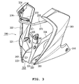
- a straddle-type vehicle 1000 includes an under cowl 300 covering both left and right sides of an engine 200 attached to a body frame 100. More specifically, in this embodiment, as shown in Fig. 1 , the straddle-type vehicle 1000 includes a small-sized cowl 530 covering a headlamp 520 attached to a handle 510. A fuel tank 540 is arranged on a rear side of a head pipe 101 of the body frame 100 to which the handle 510 is attached. Small-sized side cowls 550 are attached to front side portions of the fuel tank 540.
- Fig. 2 shows the vehicle 100 with the under cowl 300 removed.
- the engine 200 is arranged below the fuel tank 540.
- the engine 200 is attached to the body frame 100 in a space between a front wheel 601 and a rear wheel 602 of the straddle-type vehicle 1000 and below the fuel tank 540.
- the engine 200 is arranged so that a crankcase 201 is located at a lower position and a cylinder 202 is located at an upper position.
- An oil reservoir 210 in which oil circulating in the engine 200 is accumulated, is provided below the engine 200.
- a crankshaft is arranged in the crankcase 201 to be oriented in a vehicle width direction.
- the engine 200 is attached to the body frame 100 via a plurality of brackets 121, 122, and 123.
- a lower portion of the engine 200 is attached to the brackets 121 and 123 and an upper portion of the cylinder 202 of the engine 200 is attached to the bracket 122.
- a pair of left and right brackets 122 is provided to attach the upper portion of the cylinder 202 to the body frame 100, respectively.
- a plurality of fins are provided outside of the cylinder 202.
- Brackets (footrest brackets 132) to which each footrest 131 is attached are attached to a lower portion of the body frame 100.
- attachment portions 133 to which the under cowl 300 is attached are provided in the left and right footrest brackets 132, respectively.
- an operation pedal 250 performing transmission operation is provided forward of the footrest 131 shown in Fig. 2 .
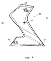
- the under cowl 300 includes a left side member 301, a right side member 302, a front side member 303, and a stay 304, as shown in Fig. 3 .
- the left side member 301 covers up at least a part of a left side of the engine 200. More specifically, in this embodiment, the left side member 301 covers up a left side of a cylinder portion of the engine 200 and a front side portion of a left side of the crankcase 201. The region is formed into a gently curved shape slightly projecting outward. Further, a lower portion of the left side member 301 extends forward of the lower portion of the body frame 100 and has a vertical width which reduces towards the front side, thus being designed to provide a desired appearance.
- connection portions 311 and 312, 314, and 316 provided on the inside of the left side member 301 are connected to a front side member 303, a stay 304 and a left attachment portion 133 (see Fig. 2 ), respectively.
- the connection portions 311 and 312, which connect to the front side member 303, are respectively provided on a front side of the lower portion of the left side member 301 and an intermediate region thereof.
- spring nuts are attached to the connection portions 311 and 312 and screwed with the front side member 301 and the left side member 304, respectively.
- the connection portions 311 and 312 are reinforced by ribs.
- the connection portion 314 attached to the stay 304 is provided in an upper portion of the left side member 301.
- connection portion 314 is formed out of a protrusion having a return on a tip end.
- the connection portion 316 connected to the left attachment portion 133 is provided on a rear side of the lower portion of the left side member 301.
- a through-hole for fastening the connection portion 316 to the left attachment portion 133 is formed in the connection portion 316.
- the through-hole is formed out of a horizontally elongated hole so as to accommodate attachment error.
- the connection portion 316 is attached to the left attachment portion 133 (see Fig. 2 ) by a rubber mount using a rubber grommet.
- the right side member 302 is formed to be substantially bilaterally symmetric with the left side member 301 and covers up at least a part of a right side of the engine 200.
- the right side member 302 covers up a right side of the cylinder portion of the engine 200 and a front side portion of a right side of the crankcase 201.
- a lower portion of the right side member 302 extends forward of that of the body frame 100.
- a region 321 into which an exhaust pipe 317 connected to the engine 200 is inserted is formed inside the right side member 302. As shown in Fig. 6 , the region 321 projects outward and forms an internal recess.
- connection portions 322 and 323, 324, and 326 connected to the front side member 303, the stay 304, and the right attachment portion 133 (see Fig. 2 ), respectively are provided inside the right side member 302.
- the connection portions 322 and 323 connected to the front side member 303 are provided on a front side of a lower portion of the right side member 303.
- a hole for locking a screw that fastens the front side member 303 to the right side member 302 is formed in the connection portion 322 and a periphery of the hole is reinforced by a rib.
- an engagement piece is provided on the connection portion 323.
- the connection portion 324 connected to the stay 304 is provided in an upper portion of the right side member 302.
- connection portion 324 is formed out of a protrusion having a return formed on a tip end.
- the connection portion 326 connected to the right attachment portion 133 is provided on a rear side of the lower portion of the right side member 302.
- a through-hole for fastening the connection portion 326 to the right attachment portion 133 is formed in the connection portion 326.
- the through-hole is similar in configuration to that of the connection portion 316 of the left side member.
- the left side member 301 and the right side member 302 are resin molded parts and molded using a pair of metal molds forming inside and outside, respectively.
- each of the respective regions of the left side member 301 and the right side member 302, such as the connection portions and the ribs stated above, is formed into a shape that enables each region to be cut away in a cutting direction of the metal molds.
- the left side member 301 and the right side member 302 can thereby be molded by the pair of metal molds without a complicated cutting structure.
- the front side member 303 is attached to the body frame 100, extends transversely on the front side of the body frame 100, and connects the left side member 301 with the right side member 302.
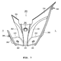
- the front side member 303 includes a rib 331, first winged portions 332 and 333, and second winged portions 334 and 335.
- An attachment portion 341 attached to the body frame 100 is provided on the rib 331.
- a fastening hole for fastening the attachment portion 341 to the bracket 121 by a bolt is formed in the attachment portion 341.
- the rib 331 extends forward and downward from a region attached to the body frame 100. Further, left and right side surfaces 351 and 352 of the rib 331 are inclined outwardly to the left and the right in a width direction as they get closer to a rear portion, respectively.
- the first winged portions 332 and 333 extend leftward and rightward from a tip or lower end of the rib 331 in the width direction, respectively.
- the second winged portions 334 and 335 extend leftward and rightward from a proximal or upper end of the rib 331, respectively above the first winged portions 332 and 333.
- Connection portions 361 and 362 connected to the left side member 301 and the right side member 302 are provided in intermediate portions of the left and right first winged portions 332 and 333, respectively.
- screw holes for screwing the connection portions 361 and 362 are formed in the connection portions 361 and 362, respectively.
- a tip end of the left first winged portion 332 is connected to a tip end of the left second winged portion 334 via a wall 363.
- the wall 363 has a complimentary shape proportional to an inner side surface of the left side member 301 and includes a connection portion 364 connected to the inner side surface of the left side member 301.
- the left side member 301 and the front side member 303 are connected with each other by connecting the connection portions 311 and 312 of the left side member 301 shown in Fig. 4 to the connection portions 361 and 364 of the front side member 303 shown in Fig. 7 .
- a wall 365 connected to an inner side surface of the right side member 302 is provided on a tip end of the right first winged portion 333.
- the wall 365 has a complimentary shape proportional to the inner side surface of the right side member 302 and includes a connection portion 366 connected to the inner side surface of the right side member 302.
- the right side member 302 and the front side member 303 are connected with each other by connecting the connection portions 322 and 323 of the right side member 302 shown in Fig. 6 to the connection portions 362 and 366 of the front side member 303 shown in Fig. 7 .
- the exhaust pipe 317 connected to the engine 200 extends to a front side of the engine 200 and, on the front side of the engine 200, extends rearward while forming a U-shaped curve. As shown in Fig. 5 , a gap allowing the exhaust pipe 317 connected to the engine 200 to pass through is formed between the tip end of the right second winged portion 335 and the right side member 302.
- the front side member 303 is a resin molded part and molded by a pair of metal molds that can cut away the front side member 303 longitudinally.
- each of the respective regions such as the rib 331, the first winged portions 332 and 333, and the second winged portions 334 and 335 is formed into a shape that enables each region to be cut away in a cutting direction of the metal molds.
- the front side member 303 can thereby be molded by the pair of metal molds without a complicated cutting structure.
- the stay 304 is attached to the body frame 100 above the front side member 303 and supports upper portions of the left side member 301 and the right side member 302.
- the stay 304 is a rod-like member.
- a bracket 125 is provided for attaching the stay 304 to a position on the body frame 100 which is above the position at which the front side member 303 is attached to the body frame 100.
- Attachment pieces 372 are welded to a central portion 371 of the stay 304.
- the stay 304 is provided on the front side of the body frame 100 and the attachment pieces 372 are attached to the bracket 125 of the body frame 100 by means of bolts.
- connection portions 314 and 324 in the upper portions of the left side member 301 and the right side member 302 are formed out of protrusions each having a return formed on a tip end, respectively. Due to this, although not shown, flanges are formed on both left and right ends of the stay 304 and fitting holes into which the protrusions of the connection portions 314 and 324 are fitted are formed in the flanges, respectively.
- a rubber ring (bush) is fitted into each of the fitting holes, thereby fitting the protrusion of each of the connection portions 314 and 324 into each fitting hole without slackening.
- This structure facilitates attaching or detaching of the left side member 301 and the right side member 302 to or from the stay 304.
- the under cowl 300 includes the left side member 301 covering up at least a part of the left side of the engine 200 and the right side member 302 covering up at least a part of the right side of the engine 200. Further, the under cowl 300 includes the front side member 303 attached to the body frame 100, transversely extending on the front side of the body frame 100, and connecting the left side member 301 with the right side member 302. In this embodiment, the front side member 303 connecting the left side member 301 with the right side member 302 is connected to the body frame 100.
- the rigidity of the under cowl 300 can be secured. Furthermore, the under cowl 300 can be attached to the body frame 100 with high accuracy. Moreover, in this embodiment, the under cowl 300 is constituted by the three members, that is, the left side member 301, the right side member 302, and the front side member 303. Due to this, the under cowl 300 can be molded by a pair of simple metal molds without a complicated cutting structure.
- the under cowl 300 can be coated in a state in which such members as the left side member 301, the right side member 302, the front side member 303, and the stay 304 are detached from the under cowl 300. Therefore, the respective members can be coated easily and effectively in accordance with, for example, a rider's preference.
- the under cowl 300 covers up both side portions of the engine 200 when viewed from a front side of the straddle-type vehicle 1000 as shown in Fig. 5 . Due to this, flowing air can be introduced from a front side of the under cowl 300 into the both sides of the engine 200, making it possible to efficiently cool the engine 200.
- the under cowl 300 covers up a front side portion of the engine 200 when viewed from a lateral side of the straddle-type vehicle 1000. Due to this, the flowing air can be efficiently introduced from the front side of the under cowl 300 into the engine 200. The engine 200 can thereby be efficiently cooled. Further, in this embodiment, the under cowl 300 does not cover up a rear side portion of the engine 200 when viewed from the lateral side of the straddle-type vehicle 1000. Due to this, the air surrounding the engine 200 can be promptly released during running. The engine 200 can thereby be efficiently cooled.
- the straddle-type vehicle 1000 includes the stay 304 attached to the body frame 100 above the front side member 303, and the stay 304 supports the upper portions of the left side member 301 and the right side member 302, respectively. Furthermore, in this embodiment, the lower portions 316 and 326 of the left side member 301 and the right side member 302, respectively are attached to the bracket attached to the body frame 100 (to be specific, the attachment portion 133 provided on the footrest bracket 312). This can further improve the rigidity of the under cowl 300 and attachment position accuracy.
- the front side member 303 includes the rib 331 extending forward and downward from the region attached to the body frame 100 and the first winged portions 332 and 333 extending leftward and rightward from the tip end of the rib 331 in the width direction.
- the first winged portions 332 and 333 are connected to the left side member 301 and the right side member 302, respectively.
- the left and right side surfaces 351 and 352 of the rib 331 are inclined outwardly to the left and the right in a width direction as they get closer to the rear portion, respectively.
- the front side member 303 also includes the second winged portions 334 and 335 extending leftward and rightward from the proximal end of the rib 331.
- the left second winged portion 334 is connected to the left side member 301.
- shapes of the rib 331, the first winged portions 332 and 333, and the second winged portions 334 and 335 enable the rigidity of the under cowl 300 to be improved, the flowing air to be introduced into the periphery of the engine 200 during running, and the engine 200 to be efficiently cooled.
- the gap allowing the exhaust pipe 317 connected to the engine 200 to pass through is formed in the front side member 303. Due to this, the under cowl 300 can be arranged without disturbing insertion of the exhaust pipe 317.
- the straddle-type vehicle according to one embodiment of the present invention has been described so far based on the drawings. However, the present invention is not limited to the above-stated embodiment.
- the respective shapes of the left side member, the right side member, the front side member, and the stay, the attachment structure of the under cowl to the body frame, connection structures of the left side member, the right side member, the front side member, and the stay that constitute the under cowl and the like are not limited to the above-stated embodiment but can be variously changed.
- the front side member includes the second winged portions extending leftward and rightward from the rib, respectively and the left second winged portion is connected to the left side member.
- the right second winged portion may be connected to the right side member.
- the front side member includes the second winged portions extending leftward and rightward from the rib
- the left and right second winged portions may be connected to the left side member and the right side member, respectively.
- the present invention is not limited to the above-stated embodiment but can be applied to various types of straddle-type vehicles.
Abstract
Description
- The present invention relates to a straddle-type vehicle and particularly relates to an under cowl of a straddle-type vehicle.
- Straddle-type vehicles are known which include a cowl or cowling for reducing air resistance during running. Examples of such a cowl include an under cowl which covers peripheries of a cylinder block or a cylinder head of an engine. For example, Japanese Examined Patent Publication No.
3-62590 - It is desirable in the art to improve rigidity of an under cowl capably withstand air resistance during running. It is also desirable to contrive a shape of the under cowl so as to be able to introduce flowing air into the engine with high efficiency.
- According to a first aspect of the present invention there is provided a straddle-type vehicle comprising:
- an engine;
- a body frame; and
- an under cowl including:
- a left side member covering at least a part of the left side of the engine;
- a right side member covering at least a part of the right side of the engine; and
- a front side member attached to the body frame and extending transversely of the body frame to connect the left side member with the right side member.
- The under cowl may cover both side portions of the engine when viewed from a front side of the straddle-type vehicle.
- The under cowl may cover a front side portion of the engine when viewed from a lateral side of the straddle-type vehicle.
- The straddle-type vehicle may comprise a stay attached to the body frame and supporting upper portions of the left side member and the right side member. The stay may be attached to the body frame above the front side member.
- A lower portion of each of the left side member and the right side member may be attached to a bracket attached to the body frame.
- The front side member may includes:
- a rib extending forward and downward from a region attached to the body frame; and
- a first winged portion extending transversely from a tip end of the rib in a width direction.
- The first winged portion may be connected to the left side member and the right side member.
- Left and right side surfaces of the rib may incline outwardly to the left and the right in a width direction from the tip end of the rib.
- The straddle-type vehicle may comprise a second winged portion extending transversely from a proximal end portion of the rib.
- The second winged portion may be connected to the left side member and/or the right side member.
- A gap allowing an exhaust pipe connected to the engine to pass through may be formed in the front side member.
- The front side member may extend transversely on a front side of the body frame.
- According to a second aspect of the present invention there is provided an under cowl for a straddle-type vehicle comprising:
- a left side member adapted to cover at least a part of a left side of an engine;
- a right side member adapted to cover at least a part of a right side of an engine; and
- a front side member connecting the left side member with the right side member, wherein the front side member is adapted to be attached to a vehicle body frame and to extend transversely of the body frame.
- A straddle-type vehicle according to a further aspect of the present invention includes an under cowl covering up both left and right sides of an engine attached to a lower portion of a body frame. The under cowl includes a left side member covering up at least a part of the left side of the engine and a right side member covering up at least a part of the right side of the engine. The under cowl also includes a front side member attached to the body frame, extending transversely on a front side of the body frame, and connecting the left side member with the right side member.
- The under cowl according to the present invention includes the front side member attached to the body frame, extending transversely on the front side of the body frame, and connecting the left side member with the right side member. Therefore, rigidity of the under cowl can be improved.
- These and other aspects of the present invention will now be described, by way of example only, with reference to the accompanying drawings, in which:
-
Fig. 1 is a side view of a straddle-type vehicle according to one embodiment of the present invention; -
Fig. 2 is a side view showing a state in which an under cowl is detached from the straddle-type vehicle according to one embodiment of the present invention; -
Fig. 3 is a perspective view showing the under cowl of the straddle-type vehicle according to one embodiment of the present invention; -
Fig. 4 is a side view showing a left side member of the under cowl of the straddle-type vehicle according to one embodiment of the present invention; -
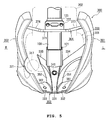
Fig. 5 is a front view showing a state in which the under cowl of the straddle-type vehicle according to one embodiment of the present invention is attached to a body frame; -
Fig. 6 is a side view showing a right side member of the under cowl of the straddle-type vehicle according to one embodiment of the present invention; and -
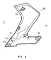
Fig. 7 is a front view showing a front side member of the under cowl of the straddle-type vehicle according to one embodiment of the present invention. - A straddle-type vehicle according to one embodiment of the present invention will be described hereinafter with reference to the drawings. In the drawings, members or regions exhibiting the same functions are denoted by the same reference symbols, respectively. Further, the present invention is not limited to the following embodiment. Moreover, if expressions such as "front", "rear", "left", "right", "upper", and "lower" are used when referring to the straddle-type vehicle, they are according to directions as seen from a rider in a state in which the rider rides on the straddle-type vehicle in an ordinary riding posture, respectively. Furthermore, a front side of the vehicle is denoted by "Fr", a rear side thereof is denoted by "Rr", a left side thereof is denoted by "L", and a right side thereof is denoted by "R" as necessary. Each drawing is shown on premise that the drawing is seen in a direction of reference symbols.
- As shown in
Fig. 1 , a straddle-type vehicle 1000 according to one embodiment of the present invention includes an undercowl 300 covering both left and right sides of anengine 200 attached to abody frame 100. More specifically, in this embodiment, as shown inFig. 1 , the straddle-type vehicle 1000 includes a small-sizedcowl 530 covering aheadlamp 520 attached to ahandle 510. Afuel tank 540 is arranged on a rear side of ahead pipe 101 of thebody frame 100 to which thehandle 510 is attached. Small-sizedside cowls 550 are attached to front side portions of thefuel tank 540. -
Fig. 2 shows thevehicle 100 with the undercowl 300 removed. As shown inFig. 2 , theengine 200 is arranged below thefuel tank 540. In this embodiment, theengine 200 is attached to thebody frame 100 in a space between afront wheel 601 and arear wheel 602 of the straddle-type vehicle 1000 and below thefuel tank 540. Theengine 200 is arranged so that acrankcase 201 is located at a lower position and acylinder 202 is located at an upper position. Anoil reservoir 210, in which oil circulating in theengine 200 is accumulated, is provided below theengine 200. A crankshaft is arranged in thecrankcase 201 to be oriented in a vehicle width direction. Theengine 200 is attached to thebody frame 100 via a plurality ofbrackets engine 200 is attached to thebrackets cylinder 202 of theengine 200 is attached to thebracket 122. Although not shown, a pair of left andright brackets 122 is provided to attach the upper portion of thecylinder 202 to thebody frame 100, respectively. In thisengine 200, a plurality of fins are provided outside of thecylinder 202. Brackets (footrest brackets 132) to which eachfootrest 131 is attached are attached to a lower portion of thebody frame 100. Further,attachment portions 133 to which the undercowl 300 is attached are provided in the left andright footrest brackets 132, respectively. Moreover, as shown inFig. 1 , anoperation pedal 250 performing transmission operation is provided forward of thefootrest 131 shown inFig. 2 . - In this embodiment, the under
cowl 300 includes aleft side member 301, aright side member 302, afront side member 303, and astay 304, as shown inFig. 3 . - As shown in
Fig. 1 , theleft side member 301 covers up at least a part of a left side of theengine 200. More specifically, in this embodiment, theleft side member 301 covers up a left side of a cylinder portion of theengine 200 and a front side portion of a left side of thecrankcase 201. The region is formed into a gently curved shape slightly projecting outward. Further, a lower portion of theleft side member 301 extends forward of the lower portion of thebody frame 100 and has a vertical width which reduces towards the front side, thus being designed to provide a desired appearance. - As shown in
Fig. 4 ,connection portions left side member 301 are connected to afront side member 303, astay 304 and a left attachment portion 133 (seeFig. 2 ), respectively. Theconnection portions front side member 303, are respectively provided on a front side of the lower portion of theleft side member 301 and an intermediate region thereof. Although not shown, spring nuts are attached to theconnection portions front side member 301 and theleft side member 304, respectively. Theconnection portions connection portion 314 attached to thestay 304 is provided in an upper portion of theleft side member 301. In this embodiment, theconnection portion 314 is formed out of a protrusion having a return on a tip end. Theconnection portion 316 connected to the left attachment portion 133 (seeFig. 2 ) is provided on a rear side of the lower portion of theleft side member 301. In this embodiment, a through-hole for fastening theconnection portion 316 to the left attachment portion 133 (seeFig. 2 ) is formed in theconnection portion 316. The through-hole is formed out of a horizontally elongated hole so as to accommodate attachment error. Theconnection portion 316 is attached to the left attachment portion 133 (seeFig. 2 ) by a rubber mount using a rubber grommet. - As shown in
Fig. 3 , theright side member 302 is formed to be substantially bilaterally symmetric with theleft side member 301 and covers up at least a part of a right side of theengine 200. In this embodiment, although not shown, theright side member 302 covers up a right side of the cylinder portion of theengine 200 and a front side portion of a right side of thecrankcase 201. Furthermore, a lower portion of theright side member 302 extends forward of that of thebody frame 100. In this embodiment, as shown inFig. 5 , aregion 321 into which anexhaust pipe 317 connected to theengine 200 is inserted is formed inside theright side member 302. As shown inFig. 6 , theregion 321 projects outward and forms an internal recess. - As shown in
Fig. 6 ,connection portions front side member 303, thestay 304, and the right attachment portion 133 (seeFig. 2 ), respectively are provided inside theright side member 302. Theconnection portions front side member 303 are provided on a front side of a lower portion of theright side member 303. A hole for locking a screw that fastens thefront side member 303 to theright side member 302 is formed in theconnection portion 322 and a periphery of the hole is reinforced by a rib. Further, an engagement piece is provided on theconnection portion 323. Theconnection portion 324 connected to thestay 304 is provided in an upper portion of theright side member 302. In this embodiment, theconnection portion 324 is formed out of a protrusion having a return formed on a tip end. Theconnection portion 326 connected to the right attachment portion 133 (seeFig. 2 ) is provided on a rear side of the lower portion of theright side member 302. In this embodiment, a through-hole for fastening theconnection portion 326 to the right attachment portion 133 (seeFig. 2 ) is formed in theconnection portion 326. The through-hole is similar in configuration to that of theconnection portion 316 of the left side member. - In this embodiment, the
left side member 301 and theright side member 302 are resin molded parts and molded using a pair of metal molds forming inside and outside, respectively. In other words, each of the respective regions of theleft side member 301 and theright side member 302, such as the connection portions and the ribs stated above, is formed into a shape that enables each region to be cut away in a cutting direction of the metal molds. Theleft side member 301 and theright side member 302 can thereby be molded by the pair of metal molds without a complicated cutting structure. - As shown in
Fig. 5 , thefront side member 303 is attached to thebody frame 100, extends transversely on the front side of thebody frame 100, and connects theleft side member 301 with theright side member 302. - In this embodiment, as shown in
Fig. 5 , thefront side member 303 includes arib 331, firstwinged portions winged portions attachment portion 341 attached to thebody frame 100 is provided on therib 331. In this embodiment, a fastening hole for fastening theattachment portion 341 to thebracket 121 by a bolt is formed in theattachment portion 341. As shown inFig. 5 , therib 331 extends forward and downward from a region attached to thebody frame 100. Further, left and right side surfaces 351 and 352 of therib 331 are inclined outwardly to the left and the right in a width direction as they get closer to a rear portion, respectively. - As shown in
Fig. 7 , the firstwinged portions rib 331 in the width direction, respectively. The secondwinged portions rib 331, respectively above the firstwinged portions Connection portions left side member 301 and theright side member 302 are provided in intermediate portions of the left and right firstwinged portions connection portions connection portions winged portion 332 is connected to a tip end of the left secondwinged portion 334 via awall 363. Thewall 363 has a complimentary shape proportional to an inner side surface of theleft side member 301 and includes aconnection portion 364 connected to the inner side surface of theleft side member 301. In this embodiment, theleft side member 301 and thefront side member 303 are connected with each other by connecting theconnection portions left side member 301 shown inFig. 4 to theconnection portions front side member 303 shown inFig. 7 . - Moreover, in this embodiment, as shown in
Fig. 7 , awall 365 connected to an inner side surface of theright side member 302 is provided on a tip end of the right firstwinged portion 333. Thewall 365 has a complimentary shape proportional to the inner side surface of theright side member 302 and includes aconnection portion 366 connected to the inner side surface of theright side member 302. In this embodiment, theright side member 302 and thefront side member 303 are connected with each other by connecting theconnection portions right side member 302 shown inFig. 6 to theconnection portions front side member 303 shown inFig. 7 . Furthermore, in this embodiment, theexhaust pipe 317 connected to theengine 200 extends to a front side of theengine 200 and, on the front side of theengine 200, extends rearward while forming a U-shaped curve. As shown inFig. 5 , a gap allowing theexhaust pipe 317 connected to theengine 200 to pass through is formed between the tip end of the right secondwinged portion 335 and theright side member 302. - In this embodiment, the
front side member 303 is a resin molded part and molded by a pair of metal molds that can cut away thefront side member 303 longitudinally. In other words, each of the respective regions such as therib 331, the firstwinged portions winged portions front side member 303 can thereby be molded by the pair of metal molds without a complicated cutting structure. - As shown in
Fig. 5 , thestay 304 is attached to thebody frame 100 above thefront side member 303 and supports upper portions of theleft side member 301 and theright side member 302. In this embodiment, thestay 304 is a rod-like member. Abracket 125 is provided for attaching thestay 304 to a position on thebody frame 100 which is above the position at which thefront side member 303 is attached to thebody frame 100.Attachment pieces 372 are welded to acentral portion 371 of thestay 304. Thestay 304 is provided on the front side of thebody frame 100 and theattachment pieces 372 are attached to thebracket 125 of thebody frame 100 by means of bolts. Left andright side portions stay 304 extend obliquely rearward and are connected to theconnection portion left side member 301 and theright side member 302 shown inFigs. 4 and6 , respectively. In this embodiment, theconnection portions left side member 301 and theright side member 302 are formed out of protrusions each having a return formed on a tip end, respectively. Due to this, although not shown, flanges are formed on both left and right ends of thestay 304 and fitting holes into which the protrusions of theconnection portions connection portions left side member 301 and theright side member 302 to or from thestay 304. - A structure of the
under cowl 300 according to this embodiment has been described so far. The undercowl 300 includes theleft side member 301 covering up at least a part of the left side of theengine 200 and theright side member 302 covering up at least a part of the right side of theengine 200. Further, the undercowl 300 includes thefront side member 303 attached to thebody frame 100, transversely extending on the front side of thebody frame 100, and connecting theleft side member 301 with theright side member 302. In this embodiment, thefront side member 303 connecting theleft side member 301 with theright side member 302 is connected to thebody frame 100. Due to this, as compared with an instance in which a member corresponding to the front side member is not connected to thebody frame 100 as disclosed in the Japanese Examined Patent Publication No.3-62590 under cowl 300 can be secured. Furthermore, the undercowl 300 can be attached to thebody frame 100 with high accuracy. Moreover, in this embodiment, the undercowl 300 is constituted by the three members, that is, theleft side member 301, theright side member 302, and thefront side member 303. Due to this, the undercowl 300 can be molded by a pair of simple metal molds without a complicated cutting structure. Further, the undercowl 300 can be coated in a state in which such members as theleft side member 301, theright side member 302, thefront side member 303, and thestay 304 are detached from the undercowl 300. Therefore, the respective members can be coated easily and effectively in accordance with, for example, a rider's preference. - Furthermore, in this embodiment, the under
cowl 300 covers up both side portions of theengine 200 when viewed from a front side of the straddle-type vehicle 1000 as shown inFig. 5 . Due to this, flowing air can be introduced from a front side of theunder cowl 300 into the both sides of theengine 200, making it possible to efficiently cool theengine 200. - Moreover, as shown in
Fig. 1 , the undercowl 300 covers up a front side portion of theengine 200 when viewed from a lateral side of the straddle-type vehicle 1000. Due to this, the flowing air can be efficiently introduced from the front side of theunder cowl 300 into theengine 200. Theengine 200 can thereby be efficiently cooled. Further, in this embodiment, the undercowl 300 does not cover up a rear side portion of theengine 200 when viewed from the lateral side of the straddle-type vehicle 1000. Due to this, the air surrounding theengine 200 can be promptly released during running. Theengine 200 can thereby be efficiently cooled. - Furthermore, in this embodiment, the straddle-
type vehicle 1000 includes thestay 304 attached to thebody frame 100 above thefront side member 303, and thestay 304 supports the upper portions of theleft side member 301 and theright side member 302, respectively. Furthermore, in this embodiment, thelower portions left side member 301 and theright side member 302, respectively are attached to the bracket attached to the body frame 100 (to be specific, theattachment portion 133 provided on the footrest bracket 312). This can further improve the rigidity of theunder cowl 300 and attachment position accuracy. - Additionally, in this embodiment, the
front side member 303 includes therib 331 extending forward and downward from the region attached to thebody frame 100 and the firstwinged portions rib 331 in the width direction. The firstwinged portions left side member 301 and theright side member 302, respectively. The left and right side surfaces 351 and 352 of therib 331 are inclined outwardly to the left and the right in a width direction as they get closer to the rear portion, respectively. Thefront side member 303 also includes the secondwinged portions rib 331. The left secondwinged portion 334 is connected to theleft side member 301. In this embodiment, shapes of therib 331, the firstwinged portions winged portions under cowl 300 to be improved, the flowing air to be introduced into the periphery of theengine 200 during running, and theengine 200 to be efficiently cooled. - In this embodiment, the gap allowing the
exhaust pipe 317 connected to theengine 200 to pass through is formed in thefront side member 303. Due to this, the undercowl 300 can be arranged without disturbing insertion of theexhaust pipe 317. - The straddle-type vehicle according to one embodiment of the present invention has been described so far based on the drawings. However, the present invention is not limited to the above-stated embodiment.
- For example, the respective shapes of the left side member, the right side member, the front side member, and the stay, the attachment structure of the under cowl to the body frame, connection structures of the left side member, the right side member, the front side member, and the stay that constitute the under cowl and the like are not limited to the above-stated embodiment but can be variously changed. For example, in the above-stated embodiment, the front side member includes the second winged portions extending leftward and rightward from the rib, respectively and the left second winged portion is connected to the left side member. Alternatively, the right second winged portion may be connected to the right side member. Further, while the front side member includes the second winged portions extending leftward and rightward from the rib, the left and right second winged portions may be connected to the left side member and the right side member, respectively. Furthermore, the present invention is not limited to the above-stated embodiment but can be applied to various types of straddle-type vehicles.
-
- 100
- Body frame
- 101
- Head pipe
- 121
- to 123, 125 Bracket
- 131
- Footrest
- 132
- Footrest bracket (bracket)
- 133
- Attachment portion
- 200
- Engine
- 201
- Crankcase
- 202
- Cylinder
- 300
- Under cowl
- 301
- Left side member
- 302
- Right side member
- 303
- Front side member
- 304
- Stay
- 317
- Exhaust pipe
- 321
- Region into which exhaust pipe is inserted
- 331
- Rib
- 332, 333
- First winged portion
- 334, 335
- Second winged portion
- 351, 352
- Left and right side surfaces of rib
- 363
- Wall
- 365
- Wall
- 510
- Handle
- 520
- Headlamp
- 530
- Cowl
- 540
- Fuel tank
- 550
- Side cowl
- 601
- Front wheel
- 602
- Rear wheel
- 1000
- Straddle-type vehicle
Claims (13)
- A straddle-type vehicle (1000) comprising:an engine (200);a body frame (100); andan under cowl (300) including:a left side member (301) covering at least a part of the left side of the engine (200);a right side member (302) covering at least a part of the right side of the engine (200); anda front side member (303) attached to the body frame (100) and extending transversely of the body frame (100) to connect the left side member (301) with the right side member (302).
- The straddle-type vehicle (1000) according to claim 1, wherein the under cowl (300) covers both side portions of the engine (200) when viewed from a front side of the straddle-type vehicle (1000).
- The straddle-type vehicle (1000) according to claim 1 or 2, wherein the under cowl (300) covers a front side portion of the engine (200) when viewed from a lateral side of the straddle-type vehicle (1000).
- The straddle-type vehicle (1000) according to claim 1, 2 or 3, comprising a stay (304) attached to the body frame (100) and supporting a portion of the left side member (301) and the right side member (302).
- The straddle-type vehicle (1000) according to claim 4, wherein the stay (304) is attached to the body frame (100) above the front side member (303).
- The straddle-type vehicle (1000) according to any preceding claim, wherein a lower portion of each of the left side member (301) and the right side member (302) is attached to a bracket (132) attached to the body frame (100).
- The straddle-type vehicle (1000) according to any preceding claim, wherein the front side member (303) includes:a rib (331) extending forward and downward from a region attached to the body frame (100); anda first winged portion (332, 333) extending transversely from a tip end of the rib (331) in a width direction, wherein the first winged portion (332, 333) is connected to the left side member (301) and the right side member (302).
- The straddle-type vehicle (1000) according to claim 7, wherein left and right side surfaces (351, 352) of the rib (331) incline outwardly to the left and the right in a width direction from the tip end of the rib (331).
- The straddle-type vehicle (1000) according to claim 7 or 8, comprising a second winged portion (334, 335) extending transversely from a proximal end portion of the rib (331).
- The straddle-type vehicle (1000) according to claim 9, wherein the second winged portion (334, 335) is connected to at least one of the left side member (301) and the right side member (302).
- The straddle-type vehicle (1000) according to any preceding claim, wherein a gap allowing an exhaust pipe (317) connected to the engine (200) to pass through is formed in the front side member (303).
- The straddle-type vehicle (1000) according to any preceding claim, wherein the front side member (303) extends transversely on a front side of the body frame (100).
- An under cowl (300) for a straddle-type vehicle (1000) comprising:a left side member (301) adapted to cover at least a part of a left side of an engine (200);a right side member (301) adapted to cover at least a part of a right side of an engine (200); anda front side member (303) connecting the left side member (301) with the right side member (302), wherein the front side member (303) is adapted to be attached to a vehicle body frame (100) and to extend transversely of the body frame (100).
Applications Claiming Priority (1)
| Application Number | Priority Date | Filing Date | Title |
|---|---|---|---|
| JP2007338782A JP2009154840A (en) | 2007-12-28 | 2007-12-28 | Saddle-ride type vehicle |
Publications (3)
| Publication Number | Publication Date |
|---|---|
| EP2077221A2 true EP2077221A2 (en) | 2009-07-08 |
| EP2077221A3 EP2077221A3 (en) | 2011-01-19 |
| EP2077221B1 EP2077221B1 (en) | 2013-10-16 |
Family
ID=40506458
Family Applications (1)
| Application Number | Title | Priority Date | Filing Date |
|---|---|---|---|
| EP20080254122 Active EP2077221B1 (en) | 2007-12-28 | 2008-12-23 | Straddle-type vehicle |
Country Status (6)
| Country | Link |
|---|---|
| EP (1) | EP2077221B1 (en) |
| JP (1) | JP2009154840A (en) |
| CN (1) | CN101468683B (en) |
| BR (1) | BRPI0805537B1 (en) |
| ES (1) | ES2438770T3 (en) |
| TW (1) | TWI359761B (en) |
Families Citing this family (5)
| Publication number | Priority date | Publication date | Assignee | Title |
|---|---|---|---|---|
| JP5466452B2 (en) * | 2009-07-31 | 2014-04-09 | 本田技研工業株式会社 | Scooter type vehicle |
| JP5457760B2 (en) * | 2009-08-28 | 2014-04-02 | 本田技研工業株式会社 | Protective cover structure for saddle-ride type vehicle engine case |
| JP5455509B2 (en) * | 2009-08-31 | 2014-03-26 | 本田技研工業株式会社 | Under cowl structure for saddle-ride type vehicles |
| JP5566708B2 (en) * | 2010-01-27 | 2014-08-06 | 本田技研工業株式会社 | Cowling structure of saddle riding type vehicle |
| CN105235791B (en) * | 2014-07-07 | 2019-12-24 | 雅马哈发动机株式会社 | Saddle-ride type vehicle |
Citations (1)
| Publication number | Priority date | Publication date | Assignee | Title |
|---|---|---|---|---|
| JPH0362590B2 (en) | 1981-09-30 | 1991-09-26 | Yamaha Motor Co Ltd |
Family Cites Families (3)
| Publication number | Priority date | Publication date | Assignee | Title |
|---|---|---|---|---|
| JPS5980182U (en) * | 1982-11-22 | 1984-05-30 | 川崎重工業株式会社 | Motorcycle fairing |
| JP4438399B2 (en) * | 2003-12-19 | 2010-03-24 | スズキ株式会社 | Motorcycle cowling mounting structure |
| JP4309876B2 (en) * | 2005-08-09 | 2009-08-05 | 川崎重工業株式会社 | Motorcycle |
-
2007
- 2007-12-28 JP JP2007338782A patent/JP2009154840A/en active Pending
-
2008
- 2008-10-07 TW TW97138602A patent/TWI359761B/en active
- 2008-12-23 EP EP20080254122 patent/EP2077221B1/en active Active
- 2008-12-23 ES ES08254122T patent/ES2438770T3/en active Active
- 2008-12-24 CN CN2008101844276A patent/CN101468683B/en active Active
- 2008-12-29 BR BRPI0805537A patent/BRPI0805537B1/en active IP Right Grant
Patent Citations (1)
| Publication number | Priority date | Publication date | Assignee | Title |
|---|---|---|---|---|
| JPH0362590B2 (en) | 1981-09-30 | 1991-09-26 | Yamaha Motor Co Ltd |
Also Published As
| Publication number | Publication date |
|---|---|
| TWI359761B (en) | 2012-03-11 |
| EP2077221B1 (en) | 2013-10-16 |
| CN101468683B (en) | 2012-06-13 |
| BRPI0805537A2 (en) | 2009-08-25 |
| CN101468683A (en) | 2009-07-01 |
| BRPI0805537B1 (en) | 2018-12-18 |
| ES2438770T3 (en) | 2014-01-20 |
| EP2077221A3 (en) | 2011-01-19 |
| TW200936430A (en) | 2009-09-01 |
| JP2009154840A (en) | 2009-07-16 |
Similar Documents
| Publication | Publication Date | Title |
|---|---|---|
| US8881859B2 (en) | Air guiding structure for motorcycles | |
| US7651112B2 (en) | Motorcycle with grab bar attached to body frame below seat | |
| US8631888B2 (en) | Cowling structure for saddle-ride type vehicle | |
| US7137722B2 (en) | Motorcycle front body structure | |
| US8899668B2 (en) | Air guide structure for saddle type vehicle | |
| US5715904A (en) | Baffle structure for a motorcycle | |
| US8051938B2 (en) | Seat mounting structure for motorcycle, and motorcycle incorporating same | |
| EP1794046B1 (en) | Vehicle body cover structure in motorcycle | |
| US8783399B2 (en) | Saddle-riding type vehicle including multi-part shroud | |
| EP1911945A1 (en) | Exhaust system for motorcycle | |
| US20170057338A1 (en) | Side cover body for motorcycle | |
| EP1794047B1 (en) | Handle cover apparatus for a motorcycle | |
| US11407464B2 (en) | Front structure of saddle riding vehicle | |
| EP2077221B1 (en) | Straddle-type vehicle | |
| US20150083512A1 (en) | Body cover for straddle type vehicle, and straddle type vehicle including same | |
| EP2161187A1 (en) | Motorcycle | |
| JP6130119B2 (en) | Motorcycle | |
| JP4720482B2 (en) | Motorcycle frame cover | |
| EP2077220B1 (en) | Straddle-type vehicle | |
| EP2075188B1 (en) | Straddle-type vehicle | |
| EP3628577B1 (en) | Saddled vehicle | |
| EP2711277B1 (en) | Frame structure for saddle-riding type automotive vehicle | |
| JP3159286U (en) | Saddle riding vehicle | |
| KR100953603B1 (en) | Leg shield structure of automatic two-wheeled vehicle | |
| WO2017018309A1 (en) | Saddle riding type vehicle |
Legal Events
| Date | Code | Title | Description |
|---|---|---|---|
| PUAI | Public reference made under article 153(3) epc to a published international application that has entered the european phase |
Free format text: ORIGINAL CODE: 0009012 |
|
| 17P | Request for examination filed |
Effective date: 20090106 |
|
| AK | Designated contracting states |
Kind code of ref document: A2 Designated state(s): AT BE BG CH CY CZ DE DK EE ES FI FR GB GR HR HU IE IS IT LI LT LU LV MC MT NL NO PL PT RO SE SI SK TR |
|
| AX | Request for extension of the european patent |
Extension state: AL BA MK RS |
|
| PUAL | Search report despatched |
Free format text: ORIGINAL CODE: 0009013 |
|
| AK | Designated contracting states |
Kind code of ref document: A3 Designated state(s): AT BE BG CH CY CZ DE DK EE ES FI FR GB GR HR HU IE IS IT LI LT LU LV MC MT NL NO PL PT RO SE SI SK TR |
|
| AX | Request for extension of the european patent |
Extension state: AL BA MK RS |
|
| AKX | Designation fees paid |
Designated state(s): AT BE BG CH CY CZ DE DK EE ES FI FR GB GR HR HU IE IS IT LI LT LU LV MC MT NL NO PL PT RO SE SI SK TR |
|
| GRAP | Despatch of communication of intention to grant a patent |
Free format text: ORIGINAL CODE: EPIDOSNIGR1 |
|
| GRAS | Grant fee paid |
Free format text: ORIGINAL CODE: EPIDOSNIGR3 |
|
| GRAP | Despatch of communication of intention to grant a patent |
Free format text: ORIGINAL CODE: EPIDOSNIGR1 |
|
| INTG | Intention to grant announced |
Effective date: 20130813 |
|
| GRAA | (expected) grant |
Free format text: ORIGINAL CODE: 0009210 |
|
| AK | Designated contracting states |
Kind code of ref document: B1 Designated state(s): AT BE BG CH CY CZ DE DK EE ES FI FR GB GR HR HU IE IS IT LI LT LU LV MC MT NL NO PL PT RO SE SI SK TR |
|
| REG | Reference to a national code |
Ref country code: GB Ref legal event code: FG4D |
|
| REG | Reference to a national code |
Ref country code: CH Ref legal event code: EP |
|
| REG | Reference to a national code |
Ref country code: IE Ref legal event code: FG4D |
|
| REG | Reference to a national code |
Ref country code: AT Ref legal event code: REF Ref document number: 636348 Country of ref document: AT Kind code of ref document: T Effective date: 20131115 |
|
| REG | Reference to a national code |
Ref country code: DE Ref legal event code: R096 Ref document number: 602008028105 Country of ref document: DE Effective date: 20131212 |
|
| REG | Reference to a national code |
Ref country code: ES Ref legal event code: FG2A Ref document number: 2438770 Country of ref document: ES Kind code of ref document: T3 Effective date: 20140120 |
|
| REG | Reference to a national code |
Ref country code: NL Ref legal event code: VDEP Effective date: 20131016 |
|
| REG | Reference to a national code |
Ref country code: AT Ref legal event code: MK05 Ref document number: 636348 Country of ref document: AT Kind code of ref document: T Effective date: 20131016 |
|
| REG | Reference to a national code |
Ref country code: LT Ref legal event code: MG4D |
|
| PG25 | Lapsed in a contracting state [announced via postgrant information from national office to epo] |
Ref country code: IS Free format text: LAPSE BECAUSE OF FAILURE TO SUBMIT A TRANSLATION OF THE DESCRIPTION OR TO PAY THE FEE WITHIN THE PRESCRIBED TIME-LIMIT Effective date: 20140216 Ref country code: LT Free format text: LAPSE BECAUSE OF FAILURE TO SUBMIT A TRANSLATION OF THE DESCRIPTION OR TO PAY THE FEE WITHIN THE PRESCRIBED TIME-LIMIT Effective date: 20131016 Ref country code: HR Free format text: LAPSE BECAUSE OF FAILURE TO SUBMIT A TRANSLATION OF THE DESCRIPTION OR TO PAY THE FEE WITHIN THE PRESCRIBED TIME-LIMIT Effective date: 20131016 Ref country code: BE Free format text: LAPSE BECAUSE OF FAILURE TO SUBMIT A TRANSLATION OF THE DESCRIPTION OR TO PAY THE FEE WITHIN THE PRESCRIBED TIME-LIMIT Effective date: 20131016 Ref country code: NO Free format text: LAPSE BECAUSE OF FAILURE TO SUBMIT A TRANSLATION OF THE DESCRIPTION OR TO PAY THE FEE WITHIN THE PRESCRIBED TIME-LIMIT Effective date: 20140116 Ref country code: NL Free format text: LAPSE BECAUSE OF FAILURE TO SUBMIT A TRANSLATION OF THE DESCRIPTION OR TO PAY THE FEE WITHIN THE PRESCRIBED TIME-LIMIT Effective date: 20131016 Ref country code: FI Free format text: LAPSE BECAUSE OF FAILURE TO SUBMIT A TRANSLATION OF THE DESCRIPTION OR TO PAY THE FEE WITHIN THE PRESCRIBED TIME-LIMIT Effective date: 20131016 Ref country code: SE Free format text: LAPSE BECAUSE OF FAILURE TO SUBMIT A TRANSLATION OF THE DESCRIPTION OR TO PAY THE FEE WITHIN THE PRESCRIBED TIME-LIMIT Effective date: 20131016 |
|
| PG25 | Lapsed in a contracting state [announced via postgrant information from national office to epo] |
Ref country code: AT Free format text: LAPSE BECAUSE OF FAILURE TO SUBMIT A TRANSLATION OF THE DESCRIPTION OR TO PAY THE FEE WITHIN THE PRESCRIBED TIME-LIMIT Effective date: 20131016 Ref country code: CY Free format text: LAPSE BECAUSE OF FAILURE TO SUBMIT A TRANSLATION OF THE DESCRIPTION OR TO PAY THE FEE WITHIN THE PRESCRIBED TIME-LIMIT Effective date: 20131016 Ref country code: LV Free format text: LAPSE BECAUSE OF FAILURE TO SUBMIT A TRANSLATION OF THE DESCRIPTION OR TO PAY THE FEE WITHIN THE PRESCRIBED TIME-LIMIT Effective date: 20131016 |
|
| PG25 | Lapsed in a contracting state [announced via postgrant information from national office to epo] |
Ref country code: PT Free format text: LAPSE BECAUSE OF FAILURE TO SUBMIT A TRANSLATION OF THE DESCRIPTION OR TO PAY THE FEE WITHIN THE PRESCRIBED TIME-LIMIT Effective date: 20140217 |
|
| REG | Reference to a national code |
Ref country code: DE Ref legal event code: R097 Ref document number: 602008028105 Country of ref document: DE |
|
| PG25 | Lapsed in a contracting state [announced via postgrant information from national office to epo] |
Ref country code: EE Free format text: LAPSE BECAUSE OF FAILURE TO SUBMIT A TRANSLATION OF THE DESCRIPTION OR TO PAY THE FEE WITHIN THE PRESCRIBED TIME-LIMIT Effective date: 20131016 |
|
| REG | Reference to a national code |
Ref country code: CH Ref legal event code: PL |
|
| PLBE | No opposition filed within time limit |
Free format text: ORIGINAL CODE: 0009261 |
|
| STAA | Information on the status of an ep patent application or granted ep patent |
Free format text: STATUS: NO OPPOSITION FILED WITHIN TIME LIMIT |
|
| PG25 | Lapsed in a contracting state [announced via postgrant information from national office to epo] |
Ref country code: RO Free format text: LAPSE BECAUSE OF FAILURE TO SUBMIT A TRANSLATION OF THE DESCRIPTION OR TO PAY THE FEE WITHIN THE PRESCRIBED TIME-LIMIT Effective date: 20131016 Ref country code: MC Free format text: LAPSE BECAUSE OF FAILURE TO SUBMIT A TRANSLATION OF THE DESCRIPTION OR TO PAY THE FEE WITHIN THE PRESCRIBED TIME-LIMIT Effective date: 20131016 Ref country code: CZ Free format text: LAPSE BECAUSE OF FAILURE TO SUBMIT A TRANSLATION OF THE DESCRIPTION OR TO PAY THE FEE WITHIN THE PRESCRIBED TIME-LIMIT Effective date: 20131016 Ref country code: PL Free format text: LAPSE BECAUSE OF FAILURE TO SUBMIT A TRANSLATION OF THE DESCRIPTION OR TO PAY THE FEE WITHIN THE PRESCRIBED TIME-LIMIT Effective date: 20131016 Ref country code: SK Free format text: LAPSE BECAUSE OF FAILURE TO SUBMIT A TRANSLATION OF THE DESCRIPTION OR TO PAY THE FEE WITHIN THE PRESCRIBED TIME-LIMIT Effective date: 20131016 Ref country code: LU Free format text: LAPSE BECAUSE OF FAILURE TO SUBMIT A TRANSLATION OF THE DESCRIPTION OR TO PAY THE FEE WITHIN THE PRESCRIBED TIME-LIMIT Effective date: 20131223 |
|
| 26N | No opposition filed |
Effective date: 20140717 |
|
| GBPC | Gb: european patent ceased through non-payment of renewal fee |
Effective date: 20140116 |
|
| REG | Reference to a national code |
Ref country code: IE Ref legal event code: MM4A |
|
| REG | Reference to a national code |
Ref country code: FR Ref legal event code: ST Effective date: 20140829 |
|
| PG25 | Lapsed in a contracting state [announced via postgrant information from national office to epo] |
Ref country code: DK Free format text: LAPSE BECAUSE OF FAILURE TO SUBMIT A TRANSLATION OF THE DESCRIPTION OR TO PAY THE FEE WITHIN THE PRESCRIBED TIME-LIMIT Effective date: 20131016 |
|
| REG | Reference to a national code |
Ref country code: DE Ref legal event code: R097 Ref document number: 602008028105 Country of ref document: DE Effective date: 20140717 |
|
| PG25 | Lapsed in a contracting state [announced via postgrant information from national office to epo] |
Ref country code: CH Free format text: LAPSE BECAUSE OF NON-PAYMENT OF DUE FEES Effective date: 20131231 Ref country code: IE Free format text: LAPSE BECAUSE OF NON-PAYMENT OF DUE FEES Effective date: 20131223 Ref country code: LI Free format text: LAPSE BECAUSE OF NON-PAYMENT OF DUE FEES Effective date: 20131231 |
|
| PG25 | Lapsed in a contracting state [announced via postgrant information from national office to epo] |
Ref country code: FR Free format text: LAPSE BECAUSE OF NON-PAYMENT OF DUE FEES Effective date: 20131231 Ref country code: GB Free format text: LAPSE BECAUSE OF NON-PAYMENT OF DUE FEES Effective date: 20140116 |
|
| PG25 | Lapsed in a contracting state [announced via postgrant information from national office to epo] |
Ref country code: SI Free format text: LAPSE BECAUSE OF FAILURE TO SUBMIT A TRANSLATION OF THE DESCRIPTION OR TO PAY THE FEE WITHIN THE PRESCRIBED TIME-LIMIT Effective date: 20131016 |
|
| PG25 | Lapsed in a contracting state [announced via postgrant information from national office to epo] |
Ref country code: TR Free format text: LAPSE BECAUSE OF FAILURE TO SUBMIT A TRANSLATION OF THE DESCRIPTION OR TO PAY THE FEE WITHIN THE PRESCRIBED TIME-LIMIT Effective date: 20131016 |
|
| PG25 | Lapsed in a contracting state [announced via postgrant information from national office to epo] |
Ref country code: HU Free format text: LAPSE BECAUSE OF FAILURE TO SUBMIT A TRANSLATION OF THE DESCRIPTION OR TO PAY THE FEE WITHIN THE PRESCRIBED TIME-LIMIT; INVALID AB INITIO Effective date: 20081223 Ref country code: BG Free format text: LAPSE BECAUSE OF FAILURE TO SUBMIT A TRANSLATION OF THE DESCRIPTION OR TO PAY THE FEE WITHIN THE PRESCRIBED TIME-LIMIT Effective date: 20131016 |
|
| PG25 | Lapsed in a contracting state [announced via postgrant information from national office to epo] |
Ref country code: GR Free format text: LAPSE BECAUSE OF NON-PAYMENT OF DUE FEES Effective date: 20131016 Ref country code: MT Free format text: LAPSE BECAUSE OF FAILURE TO SUBMIT A TRANSLATION OF THE DESCRIPTION OR TO PAY THE FEE WITHIN THE PRESCRIBED TIME-LIMIT Effective date: 20131016 |
|
| PG25 | Lapsed in a contracting state [announced via postgrant information from national office to epo] |
Ref country code: GR Free format text: LAPSE BECAUSE OF FAILURE TO SUBMIT A TRANSLATION OF THE DESCRIPTION OR TO PAY THE FEE WITHIN THE PRESCRIBED TIME-LIMIT Effective date: 20140117 |
|
| PGFP | Annual fee paid to national office [announced via postgrant information from national office to epo] |
Ref country code: ES Payment date: 20230224 Year of fee payment: 15 |
|
| P01 | Opt-out of the competence of the unified patent court (upc) registered |
Effective date: 20230527 |
|
| PGFP | Annual fee paid to national office [announced via postgrant information from national office to epo] |
Ref country code: IT Payment date: 20231228 Year of fee payment: 16 Ref country code: DE Payment date: 20231214 Year of fee payment: 16 |