EP2076397B1 - Drucken auf einer rotierenden oberfläche - Google Patents
Drucken auf einer rotierenden oberfläche Download PDFInfo
- Publication number
- EP2076397B1 EP2076397B1 EP07853991A EP07853991A EP2076397B1 EP 2076397 B1 EP2076397 B1 EP 2076397B1 EP 07853991 A EP07853991 A EP 07853991A EP 07853991 A EP07853991 A EP 07853991A EP 2076397 B1 EP2076397 B1 EP 2076397B1
- Authority
- EP
- European Patent Office
- Prior art keywords
- platen
- printhead
- substrate
- image data
- printing system
- Prior art date
- Legal status (The legal status is an assumption and is not a legal conclusion. Google has not performed a legal analysis and makes no representation as to the accuracy of the status listed.)
- Active
Links
Images


Classifications
-
- B—PERFORMING OPERATIONS; TRANSPORTING
- B41—PRINTING; LINING MACHINES; TYPEWRITERS; STAMPS
- B41J—TYPEWRITERS; SELECTIVE PRINTING MECHANISMS, i.e. MECHANISMS PRINTING OTHERWISE THAN FROM A FORME; CORRECTION OF TYPOGRAPHICAL ERRORS
- B41J29/00—Details of, or accessories for, typewriters or selective printing mechanisms not otherwise provided for
- B41J29/38—Drives, motors, controls or automatic cut-off devices for the entire printing mechanism
-
- B—PERFORMING OPERATIONS; TRANSPORTING
- B41—PRINTING; LINING MACHINES; TYPEWRITERS; STAMPS
- B41J—TYPEWRITERS; SELECTIVE PRINTING MECHANISMS, i.e. MECHANISMS PRINTING OTHERWISE THAN FROM A FORME; CORRECTION OF TYPOGRAPHICAL ERRORS
- B41J29/00—Details of, or accessories for, typewriters or selective printing mechanisms not otherwise provided for
-
- B—PERFORMING OPERATIONS; TRANSPORTING
- B41—PRINTING; LINING MACHINES; TYPEWRITERS; STAMPS
- B41J—TYPEWRITERS; SELECTIVE PRINTING MECHANISMS, i.e. MECHANISMS PRINTING OTHERWISE THAN FROM A FORME; CORRECTION OF TYPOGRAPHICAL ERRORS
- B41J11/00—Devices or arrangements of selective printing mechanisms, e.g. ink-jet printers or thermal printers, for supporting or handling copy material in sheet or web form
- B41J11/008—Controlling printhead for accurately positioning print image on printing material, e.g. with the intention to control the width of margins
-
- B—PERFORMING OPERATIONS; TRANSPORTING
- B41—PRINTING; LINING MACHINES; TYPEWRITERS; STAMPS
- B41J—TYPEWRITERS; SELECTIVE PRINTING MECHANISMS, i.e. MECHANISMS PRINTING OTHERWISE THAN FROM A FORME; CORRECTION OF TYPOGRAPHICAL ERRORS
- B41J23/00—Power drives for actions or mechanisms
-
- B—PERFORMING OPERATIONS; TRANSPORTING
- B41—PRINTING; LINING MACHINES; TYPEWRITERS; STAMPS
- B41J—TYPEWRITERS; SELECTIVE PRINTING MECHANISMS, i.e. MECHANISMS PRINTING OTHERWISE THAN FROM A FORME; CORRECTION OF TYPOGRAPHICAL ERRORS
- B41J3/00—Typewriters or selective printing or marking mechanisms characterised by the purpose for which they are constructed
- B41J3/28—Typewriters or selective printing or marking mechanisms characterised by the purpose for which they are constructed for printing downwardly on flat surfaces, e.g. of books, drawings, boxes, envelopes, e.g. flat-bed ink-jet printers
-
- B—PERFORMING OPERATIONS; TRANSPORTING
- B41—PRINTING; LINING MACHINES; TYPEWRITERS; STAMPS
- B41J—TYPEWRITERS; SELECTIVE PRINTING MECHANISMS, i.e. MECHANISMS PRINTING OTHERWISE THAN FROM A FORME; CORRECTION OF TYPOGRAPHICAL ERRORS
- B41J3/00—Typewriters or selective printing or marking mechanisms characterised by the purpose for which they are constructed
- B41J3/407—Typewriters or selective printing or marking mechanisms characterised by the purpose for which they are constructed for marking on special material
- B41J3/4071—Printing on disk-shaped media, e.g. CDs
-
- G—PHYSICS
- G06—COMPUTING OR CALCULATING; COUNTING
- G06K—GRAPHICAL DATA READING; PRESENTATION OF DATA; RECORD CARRIERS; HANDLING RECORD CARRIERS
- G06K1/00—Methods or arrangements for marking the record carrier in digital fashion
-
- G—PHYSICS
- G06—COMPUTING OR CALCULATING; COUNTING
- G06K—GRAPHICAL DATA READING; PRESENTATION OF DATA; RECORD CARRIERS; HANDLING RECORD CARRIERS
- G06K15/00—Arrangements for producing a permanent visual presentation of the output data, e.g. computer output printers
- G06K15/02—Arrangements for producing a permanent visual presentation of the output data, e.g. computer output printers using printers
- G06K15/10—Arrangements for producing a permanent visual presentation of the output data, e.g. computer output printers using printers by matrix printers
- G06K15/102—Arrangements for producing a permanent visual presentation of the output data, e.g. computer output printers using printers by matrix printers using ink jet print heads
-
- G—PHYSICS
- G06—COMPUTING OR CALCULATING; COUNTING
- G06K—GRAPHICAL DATA READING; PRESENTATION OF DATA; RECORD CARRIERS; HANDLING RECORD CARRIERS
- G06K2215/00—Arrangements for producing a permanent visual presentation of the output data
- G06K2215/0082—Architecture adapted for a particular function
Definitions
- Droplet ejection devices are used for depositing droplets on a substrate.
- Ink jet printers are a type of droplet ejection device.
- Ink jet printers typically include an ink supply to a nozzle path. The nozzle path terminates in a nozzle opening from which ink drops are ejected.
- Ink drop ejection is controlled by pressurizing ink in the ink path with an actuator, which may be, for example, a piezoelectric deflector, a thermal bubble jet generator, or an electro statically deflected element.
- a typical printhead has an array of ink paths with corresponding nozzle openings and associated actuators, such that drop ejection from each nozzle opening can be independently controlled.
- each actuator is fired to selectively eject a drop at a specific pixel.location of an image as the printhead and a printing substrate are moved relative to one another.
- the nozzle openings typically have a diameter of 50 microns or less, e.g. around 35 microns, are separated a: a pitch of 100-300 nozzle/inch, have a resolution of 100 to 3000 dpi or more, and provide drop sizes of about 1 to 70 picoliters or less.
- Drop ejection frequency can be 10 kHz or more.
- US 4 066 268 A discloses a system used labeling disc records.
- the label portion therefor is formed by tracing a pattern of essentially circular grooves or arrays of dots and groove or dot-free areas in the location of the label portion, the grooved areas contrasting visually with the groove-free areas and the pattern being such that one type of area, preferably the groove-free areas, forms the legible characters and patterns to appear in the label portion.
- US 5 317 337 A discloses method and apparatus for printing label information in the form of graphics and/or characters on a disc-shaped information carrier (such as a CD).
- the label information is prepared by a data-processing system and transferred to a printer for processing. The printer then prints the label information directly on the information carrier.
- a printing system includes a platen that moves a substrate along a non-straight path (e.g., by the platen rotating about an axis of rotation) and configured to support a substrate, and a printhead configured to eject drops of an image on the substrate as it is moved along the non-straight path.
- the printing system according to the invention is defined in claim 1.
- the printhead can be an ink jet printhead.
- the printing system can have a plurality of printheads (e.g., four printheads, one for each ink color, cyan, magenta, yellow, and black).
- the system can include a printhead for depositing a coating on a surface of the substrate, or a curing station for curing the droplets on the substrate.
- the system can have a platen including a cavity for holding the substrate, a trigger that rises above a surface of the platen when the substrate is placed in the cavity.
- the system includes a key (e.g., barcode) on the platen and a reader that reads information (c.g., set-up parameters for the rotating platen) stored on the key, the reader sends the information to the imaging system
- the platen can be made of a moldable material that conforms to a shape of the substrate, and the platen can support a plurality of substrates.
- the platen can be coupled to a conveyor that moves relative to the printhead. There can also be a plurality of platens coupled to the conveyor. The method according to the invention is disclosed in claim 8.
- Implementations can include one or more of the following features. Formatting the image data can include converting the image data into bitmap raster data, applying an arc process, applying a gradient mask process, or separating the image data into cyan, magenta, yellow, and black.
- the method can also include sending the formatted image data to the printhead, curing the droplets on the substrate, or sensing the substrate in the platen and causing the printhead to deposit droplets when the substrate is sensed.
- a key can store information about the platen, and the method can include reading the information on the key and sending the information to an imaging system.
- the method can also include storing image data in an imaging system.
- the image can be comprised of dots having a certain image resolution after one revolution, and the method can further include increasing the image resolution by moving the printhead relative to the platen and printing dots in a space between the dots after the first revolution.
- Certain implementations may have one or more of the following advantages. Fewer printheads are needed to print higher resolution because the substrates can be rotated under the same printheads several times to increase the resolution.
- the platen can be used to print on a small number of substrates (e.g. customized products) or a less than full platen.
- the set-up time is minimal.
- the printing system can print on different substrates within the same platen. Rotating the substrates under the printheads can be faster than some conventional printing methods, especially for small items.
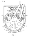
- Fig. 1 shows a printing system 10 including two printheads 12 (e.g., ink jet printheads) for depositing fluids (e.g., cyan, magenta, yellow, and black ink) onto a substrate 14 supported by a rotating platen 16.
- the platen in Fig. 1 shows a rotating platen 16 with an axis of rotation X 18.
- a substrate 14 is placed on the platen 16, the platen rotates about the axis X 18, and the printhead 12 prints on the substrate as the substrate passes under the printhead.
- the printhead prints images retrieved from an imaging system 20 e.g., a computer).
- the imaging system 20 can store, process, and send image data to the printhead 12. Processing image data can include dividing and translating the image data, such as converting the image data into a format compatible with the printer.
- the printing system in Fig. 1 operates in a circular motion.
- the imaging system 20 uses software to format the image data to account for the circular movement of the substrate relative to the printhead.
- the platen 16 supports multiple substrates 14 to be printed.
- the platen 16 can be removed and replaced with the next platen. This can be a manual or automated process.
- Fig. 2 shows a printing system 100 including a platen 102 made from a moldable material (e.g., thermoplastic material), such that the platen 102 conforms to the shape of the customized product and forms recessed cavities 104.
- the platen 102 can then hold the exact number of products to be printed.
- the platen can also be molded to hold different types of products within the same platen, such as lighters and pens.
- the platen includes a trigger 110 that rises above the surface of the platen 102 when a product is placed in a cavity 104.
- the printing system can have a trigger sensor 112 to detect a raised trigger and to communicate with the printhead 114 if there is a product in the cavity 104. This enables users to print less than a full platen.
- the printing system 200 includes a platen 202 with a key 204 (e.g., bar code, RFID tag) and a reader 206 to read the key 204 on the platen 202.
- the key 204 can provide information about the platen 202, such as the type of products on the platen 202 and set-up parameters (e.g., automatic adjustment of printhead stand-off distance).
- the reader 206 communicates with the imaging system 208, which instructs the printhead based on this information.
- a barcode on a platen can indicate that the platen holds coffee mugs.
- a barcode reader reads the barcode that the platen contains coffee mugs.
- the imaging system adjusts the printhead stand-off distance to a height that permits the mugs to pass under the printhead without damaging the head.
- the imaging system also processes the images to account for the circular motion of the mugs relative to the printhead.
- a user can manually enter into the imaging system the type of products on the platen and select the images to be printed.
- the printhead can have a home position that is a predetermined vertical or horizontal distance from the platen. This enables users to easily transfer platens on and off the printing system.
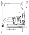
- a platen 402 could rotate about an axis that moves along a conveyor system 404, as shown in the printing system 400 of FIG. 5 .
- a rotating peg 406 could be used in place of a platen.
- Multiple rotating pegs connected to a conveyor system spin objects 408, such as compact disc (CD) or digital video disc (DVD).
- the printhead 410 prints on the spinning compact discs as they travel linearly along the conveyor, similar to single pass printing. This can be faster than scanning printing, especially for small objects.
- the printhead can print a coating on the surface of the disc or print graphics on it.
- the printhead 410, in FIG. 5 includes four colors, cyan 412, magenta 414, yellow 416, and black 418.
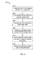
- the flowchart 300 shows how image data is processed so that the printhead can print data on a substrate supported by a rotating platen or peg.
- the image data is in a format stored by the imaging system 302 (e.g., graphic image format (gif), joint experts group (jpeg), PostScript, Printer Command Language (PCL), or other image data collection).
- the imaging system uses software to convert the image data into a format compatible with the printhead 304, such as bitmap raster data.
- the image data goes through an arc process 306 and gradient mask process 308 to compensate for the circular motion of the substrate and the image resolution variation of a substrate from the center to the edge of the platen.
- ABS image data 30 illustrated graphically in FIG. 4A
- ABS goes through an arc process that bends the image data 30 to compensate for the faster and slower portions of the substrate and correct the drop placement.
- FIG. 4B graphically shows formatted image data 40 after going through the arc process.
- the "A” is closer to the edge of the platen, therefore its size is reduced to compensate for the platen moving faster near the edge, which spaces the dots further apart.
- the "C” s enlarged because it is closer to the center, which is moving slower causing the dots to land closer together.
- the gradient mask process compensates for the variation of image boldness, in which the portion 52 of the image furthest from the center is lighter than the portion 54 closest to the center of the platen, as seen in FIG. 4C .
- the gradient mask process overlays a random matrix of white dots 60, shown in FIG. 4D , onto the image data with more white dots in the darker areas 62.
- the number of white dots decreases from the darker areas 62 to the lighter areas 64 to provide uniformity in the image boldness from the center to the edge of the platen.
- the image data can be separated into cyan, magenta, yellow, and black 310, and sent to the printhead for printing 312.
- the sequence of steps described is an example of how the image data can be processed. These steps can be rearranged, some steps can be combined into a single step, or some steps can be added or eliminated.
- the printheads used can include NOVA JA 256 or GALAXY JA 256, which are commercially available from FUJIFILM Dimatix, Inc. located in Riverside, NH.
- the printheads can print images with a resolution of about 400 dpi to about 1200 dpi.
- the substrates can be cell phones, edible items, compact discs, DVDs, specialty advertising products, such as lighters, golf balls, medallions, pens, letter openers, and any other objects.
- the objects can be customized for business or for personal use.
- the printheads can deposit ink (e.g., ultraviolet, solvent, aqueous, or hot melt ink), coatings, edible substances, plastic, or any other materials.
- the platen can be any shape, such as a circular, rectangular, or triangular. The platen can be mounted horizontally, vertically, or any other desired orientation, and can rotate around a center axis or an off-centered axis.
- the printing system in Figs. 1 and 2 shows two printheads, but the printing system can have any number of printheads or only one printhead.
- the printing system can include a printhead for depositing a coating on a substrate, such as a varnish top coat.
- the imaging system shown in Fig. 1 can support text, line art, logotypes, and graphics.
- the printing system of Figs. 1 , 2 and 3 can also include a curing station, such as an ultraviolet curing station.
- a curing station such as an ultraviolet curing station.
- the term "peg" is not limited to a particular shape or size.
- the peg can be round or square.
- the peg can have more than one prong.
- Figs. 1 , 2 and 3 shows platens and pegs to support objects, other implementations can be used to support and rotate objects relative to a printhead.
- the platens or pegs in Figs. 1 , 2 and 3 could be stationary while the printheads rotate relative to the substrates.
- the tiger can be a mechanical trigger (e.g., knob), optical trigger (e.g., laser beam), an electrical trigger, or any other type of trigger.
- the printing system 100 of FIG. 2 can print images having a certain image resolution that correlates with the nozzle pitch of the printheads 114.
- the image resolution can be increased by increasing the number of dots per inch with each revolution of the platen. For example, when the substrates pass under the head one time, the heads print an image having 100 dpi. After the first revolution, the heads are then moved from the center 116 of the platen to the outside edge a short distance (e.g., one or more pixels). During a second revolution, the heads print dots in the space between the dots from the first revolution. The image resolution after two revolutions can therefore be increased to 200 dpi. By increasing the number of revolutions, the image resolution can correspondingly increase (e.g., to 300 dpi, 600 dpi, 1200 dpi, or greater). The heads can alternatively move from the outside edge toward the center of the platen.
- This process also applies to the printing system 400 of FIG. 5 , which has rotating platens 402 on a moving conveyor 404.
- the platen can move the substrate along paths that are other than circular, for example, any non-straight path.
Landscapes
- Engineering & Computer Science (AREA)
- Physics & Mathematics (AREA)
- General Physics & Mathematics (AREA)
- Theoretical Computer Science (AREA)
- General Engineering & Computer Science (AREA)
- Mathematical Physics (AREA)
- Ink Jet (AREA)
- Handling Of Sheets (AREA)
- Coating Apparatus (AREA)
Claims (13)
- Drucksystem (10; 100; 200) umfassend:einen Druckkopf (12; 114) zum Absetzen von Tröpfchen;eine Trägerplatte (16; 102; 202) zum Tragen eines Substrats (14) und zum Bewegen des Substrats (14) entlang eines nicht geraden Pfads relativ zu dem Druckkopf (12; 114), wobei der Druckkopf (12; 114) positioniert ist zum Absetzen von Tröpfchen eines Bilds auf dem Substrat (14) während es entlang des nicht geraden Pfads bewegt wird;ein Abbildungssystem (20; 208) zum Formatieren von Bilddaten um dem nicht geraden Pfad des Substrats (14) Rechnung zu tragen und um Instruktionen an den Druckkopf (12; 114) zu senden Tröpfchen auf das Substrat (14) abzusetzen, basierend auf den formatierten Bilddaten; undeinen Schlüssel (204) auf der Trägerplatte (16; 102; 202) und ein Lesegerät (206), das die Informationen, die auf dem Schlüssel (204) gespeichert sind liest, wobei das Lesegerät (206) ausgelegt ist die Informationen an das Abbildungssystem (20, 208) zu senden, welches den Druckkopf (12; 114) basierend auf diesen Informationen instruiert.
- Drucksystem nach Anspruch 1, weiter umfassend eine Vielzahl von Druckköpfen (12; 114).
- Drucksystem nach Anspruch 1, weiter umfassend einen Druckkopf (12; 114), der ausgelegt ist eine Beschichtung auf der Oberfläche des Substrats (14) abzusetzen.
- Drucksystem nach Anspruch 1, weiter umfassend eine Aushärtstation, die ausgelegt ist die Tröpfchen auf dem Substrat auszuhärten.
- Drucksystem nach Anspruch 1, wobei die Informationen Setup-Parameter für die rotierende Trägerplatte (16; 102; 202) umfassen.
- Drucksystem nach Anspruch 1, wobei die Trägerplatte (16; 102; 202) an ein Fördermittel gekoppelt ist, welches sich relativ zu dem Druckkopf (12; 114) bewegt.
- Drucksystem nach Anspruch 1, bei dem der nicht gerade Pfad einen kreisförmigen Pfad um eine Rotationsaxe der Trägerplatte (16; 102; 202) umfasst.
- Verfahren zum Drucken, umfassend:Drehen eines Substrats (14) auf einer Trägerplatte (16; 102; 202) um eine Achse in einer kreisförmigen Bewegung um zumindest eine Umdrehung;Formatieren von Bilddaten, um der kreisförmigen Bewegung des Substrats (14) Rechnung zu tragen; undVerwenden eines Druckkopfes (12; 114), um Tröpfchen abzusetzen, in eine Richtung parallel zu der Drehachse, um ein Bild auf das Substrat (14) zu drucken, basierend auf den formatierten Bilddaten; undLesen von Informationen über die Trägerplatte, die auf einem Schlüssel (204) gespeichert sind und senden der Informationen an ein Abbildungssystem (20; 206), welches den Druckkopf (12; 114) basierend auf diesen Informationen instruiert.
- Verfahren nach Anspruch 8, wobei das Formatieren der Bilddaten Konvertieren der Bilddaten in Bitmap-Rasterdaten umfasst.
- Verfahren nach Anspruch 8, wobei das Formatieren der Bilddaten außerdem die Anwendung eines Bogenprozesses umfasst.
- Verfahren nach Anspruch 8, wobei das Formatieren der Bilddaten die Anwendung eines Gradienten-Maskierungsprozesses umfasst.
- Verfahren nach Anspruch 8, außerdem umfassend Abtasten des Substrats (14) in der Trägerplatte (16; 102; 202) und Veranlassen des Druckkopfs (12; 114) Tröpfchen abzusetzen, wenn das Substrat (14) abgetastet wurde.
- Verfahren nach Anspruch 8, wobei das aus Punkten bestehende Bild eine gewisse Auflösung nach einer Umdrehung hat und das Verfahren außerdem die Steigerung der Bildauflösung umfasst durch Bewegen des Druckkopfs (12; 114) relativ zu der Trägerplatte (16; 102; 202) und Drucken von Punkten in einen Raum zwischen den Punkten nach der ersten Umdrehung.
Applications Claiming Priority (2)
| Application Number | Priority Date | Filing Date | Title |
|---|---|---|---|
| US82949606P | 2006-10-13 | 2006-10-13 | |
| PCT/US2007/081216 WO2008048885A2 (en) | 2006-10-13 | 2007-10-12 | Printing on a rotating surface |
Publications (3)
| Publication Number | Publication Date |
|---|---|
| EP2076397A2 EP2076397A2 (de) | 2009-07-08 |
| EP2076397A4 EP2076397A4 (de) | 2010-11-03 |
| EP2076397B1 true EP2076397B1 (de) | 2012-12-05 |
Family
ID=39314753
Family Applications (1)
| Application Number | Title | Priority Date | Filing Date |
|---|---|---|---|
| EP07853991A Active EP2076397B1 (de) | 2006-10-13 | 2007-10-12 | Drucken auf einer rotierenden oberfläche |
Country Status (6)
| Country | Link |
|---|---|
| US (2) | US7946668B2 (de) |
| EP (1) | EP2076397B1 (de) |
| JP (1) | JP5350250B2 (de) |
| KR (1) | KR20090082394A (de) |
| CN (1) | CN101522429B (de) |
| WO (1) | WO2008048885A2 (de) |
Families Citing this family (14)
| Publication number | Priority date | Publication date | Assignee | Title |
|---|---|---|---|---|
| US9409414B2 (en) | 2013-04-04 | 2016-08-09 | Nike, Inc. | Vacuum cylinder with recessed portions for holding articles for printing |
| US9321257B2 (en) | 2013-04-04 | 2016-04-26 | Nike, Inc. | Cylinder with recessed portions for holding tubular articles for printing |
| US20170072417A1 (en) * | 2014-02-26 | 2017-03-16 | Scienion Ag | Method and dispenser device for depositing a substance on a target substrate |
| CN110884262B (zh) | 2014-05-20 | 2021-09-03 | 维罗斯-纯粹数字有限公司 | 打印系统及方法 |
| US10252544B2 (en) | 2014-11-13 | 2019-04-09 | The Procter & Gamble Company | Apparatus and method for depositing a substance on articles |
| JP2017535455A (ja) * | 2014-11-13 | 2017-11-30 | ザ プロクター アンド ギャンブル カンパニー | 物品を装飾するためのプロセス |
| CA2964484A1 (en) * | 2014-11-13 | 2016-05-19 | The Procter & Gamble Company | Digitally printed article |
| US20170056918A1 (en) * | 2015-08-31 | 2017-03-02 | The Procter & Gamble Company | Parallel Motion Method for Depositing a Substance on Articles |
| US10882309B2 (en) | 2017-07-25 | 2021-01-05 | Illinois Tool Works Inc. | Printing system and method |
| CN107571641A (zh) * | 2017-09-11 | 2018-01-12 | 湖北省立亮电子有限公司 | 打火机印刷机 |
| WO2019178597A1 (en) * | 2018-03-16 | 2019-09-19 | Vinventions Usa, Llc | Printing system for printing on cylindrical objects |
| WO2020072061A1 (en) * | 2018-10-04 | 2020-04-09 | Vinventions Usa, Llc | Mandrel and mounting device for receiving a hollow cylindrical object |
| WO2020046291A1 (en) * | 2018-08-29 | 2020-03-05 | Vinventions Usa, Llc | Method and printing system for printing on a top surface three-dimensional objects |
| CN116512753A (zh) * | 2022-01-24 | 2023-08-01 | 峻亦股份有限公司 | 随选列印杯子的列印方法及系统 |
Family Cites Families (38)
| Publication number | Priority date | Publication date | Assignee | Title |
|---|---|---|---|---|
| US4066268A (en) | 1972-04-21 | 1978-01-03 | Ted Bildplatten Aktiengesellschaft Aeg-Telefunken-Teldec | Disc recording provided with legible matter |
| DE3721651A1 (de) | 1987-07-01 | 1989-01-12 | Philips & Du Pont Optical | Verfahren zum bedrucken plattenfoermiger informationstraeger |
| US5173988A (en) * | 1991-06-17 | 1992-12-29 | Videojet Systems International, Inc. | Dewatering apparatus for drop marking bottles and cans |
| JPH0679885A (ja) | 1992-06-24 | 1994-03-22 | Sony Corp | 印刷方法、印刷装置、印刷ヘッド、被印刷物収納容器及びカセットの印刷方法 |
| JPH08207264A (ja) * | 1995-02-01 | 1996-08-13 | Canon Electron Inc | 印刷システムおよび印刷装置 |
| US5613790A (en) * | 1995-08-31 | 1997-03-25 | Intermec Corporation | Apparatus for normalizing top-of-form registration in a moving web printer |
| CN1154103C (zh) * | 1996-09-13 | 2004-06-16 | 三星电子株式会社 | 在光盘播放机中夹持光盘和驱动托盘的方法和装置 |
| US5730048A (en) * | 1997-01-06 | 1998-03-24 | Averill; Michael J. | System for the printing of small flat objects using direct rotary printing apparatus |
| EP0919371B1 (de) * | 1997-03-24 | 2006-07-19 | Toray Industries, Inc. | Beschichtungsvorrichtung, druckvoorichtung, bilderzeugungsvorrichtung, drucksystem und druckverfahren |
| JPH1134305A (ja) * | 1997-07-17 | 1999-02-09 | Canon Inc | 画像記録装置 |
| US6074031A (en) * | 1997-12-11 | 2000-06-13 | Compulog Corporation | Method and apparatus for printing labels on digital recording media |
| US6854841B1 (en) * | 1998-04-17 | 2005-02-15 | Elesys, Inc. | Point-of-incidence ink-curing mechanisms for radial printing |
| US7748807B2 (en) * | 1998-04-17 | 2010-07-06 | Elesys, Inc. | Off-radial-axis circular printing device and methods |
| US6910750B2 (en) * | 2000-06-02 | 2005-06-28 | Elesys, Inc. | Low-profile ink head cartridge with integrated movement mechanism and service station |
| US6264295B1 (en) * | 1998-04-17 | 2001-07-24 | Elesys, Inc. | Radial printing system and methods |
| US7497534B2 (en) * | 2000-03-21 | 2009-03-03 | Elesys, Inc. | Enhancing angular position information for a radial printing system |
| US6986559B1 (en) * | 2001-04-20 | 2006-01-17 | Elesys, Inc. | Position information apparatus and methods for radial printing |
| US6053101A (en) * | 1998-04-30 | 2000-04-25 | Hix; Clifford A. | Transfer printing press |
| FR2784933B1 (fr) * | 1998-10-22 | 2001-01-05 | Dubuit Mach | Machine a imprimer comportant au moins un poste d'impression serigraphique et au moins un poste d'impression numerique fonctionnant par jet d'encre |
| US6538767B1 (en) | 1999-03-01 | 2003-03-25 | Designer Image Technologies, Inc. | Methods and systems for printing on spherical objects |
| JP2000301707A (ja) * | 1999-04-19 | 2000-10-31 | Master Mind:Kk | 記録媒体の印刷方法 |
| US6408745B1 (en) * | 2000-01-06 | 2002-06-25 | Anatol Incorporated | Variable height print table arrangement for a screen printing apparatus |
| US20020097280A1 (en) * | 2001-01-25 | 2002-07-25 | Bertram Loper | Apparatus and method of printing on a curved surface with an ink jet printer |
| TWI223238B (en) | 2001-02-13 | 2004-11-01 | Orient Instr Comp Co Ltd | Disk adaptor for use in a printer for printing a label on an optical disk |
| US6857359B2 (en) * | 2001-07-12 | 2005-02-22 | Fuji Photo Film Co., Ltd. | Devices relating to rolled product |
| JP4259812B2 (ja) * | 2002-05-13 | 2009-04-30 | 富士フイルム株式会社 | インクジェット記録方法及びインクジェット記録装置 |
| JP3780232B2 (ja) * | 2002-07-10 | 2006-05-31 | キヤノン株式会社 | 記録装置 |
| US7463388B2 (en) * | 2003-05-29 | 2008-12-09 | Canon Kabushiki Kaisha | Image forming apparatus with control of image formation using read information |
| US6769357B1 (en) * | 2003-06-05 | 2004-08-03 | Sequa Can Machinery, Inc. | Digital can decorating apparatus |
| JP4158632B2 (ja) * | 2003-07-15 | 2008-10-01 | セイコーエプソン株式会社 | 印刷装置、印刷方法、及び、印刷システム |
| JP3988706B2 (ja) * | 2003-09-30 | 2007-10-10 | ティアック株式会社 | ディスク保持機構 |
| JP4639906B2 (ja) * | 2005-03-30 | 2011-02-23 | ブラザー工業株式会社 | 記録装置 |
| US7484820B2 (en) * | 2005-03-30 | 2009-02-03 | Brother Kogyo Kabushiki Kaisha | Recording apparatus for rotating recording medium |
| US20060249039A1 (en) * | 2005-05-06 | 2006-11-09 | Kornit Digital Ltd. | Combined stencil and digital printing system |
| US7446792B2 (en) * | 2005-06-30 | 2008-11-04 | Yamaha Corporation | Method and apparatus for forming visible image on optical disk |
| US7436421B2 (en) * | 2005-09-21 | 2008-10-14 | Hewlett-Packard Development Company, L.P. | Apparatus and methods for forming optically visible marks on a rotating media |
| US7290949B1 (en) * | 2005-10-12 | 2007-11-06 | Tallygenicom Lp | Line printer having a motorized platen that automatically adjusts to accommodate print forms of varying thickness |
| US7424851B2 (en) * | 2006-09-21 | 2008-09-16 | Landesman David A | Screen printer with platen equalizer and method of printing |
-
2007
- 2007-10-12 KR KR1020097009809A patent/KR20090082394A/ko not_active Withdrawn
- 2007-10-12 CN CN2007800382358A patent/CN101522429B/zh active Active
- 2007-10-12 EP EP07853991A patent/EP2076397B1/de active Active
- 2007-10-12 JP JP2009532598A patent/JP5350250B2/ja active Active
- 2007-10-12 US US11/871,597 patent/US7946668B2/en active Active
- 2007-10-12 WO PCT/US2007/081216 patent/WO2008048885A2/en not_active Ceased
-
2011
- 2011-05-20 US US13/112,304 patent/US9004624B2/en active Active
Also Published As
| Publication number | Publication date |
|---|---|
| WO2008048885A3 (en) | 2008-08-28 |
| US20080088653A1 (en) | 2008-04-17 |
| JP2010506752A (ja) | 2010-03-04 |
| WO2008048885A2 (en) | 2008-04-24 |
| EP2076397A4 (de) | 2010-11-03 |
| KR20090082394A (ko) | 2009-07-30 |
| CN101522429A (zh) | 2009-09-02 |
| US9004624B2 (en) | 2015-04-14 |
| JP5350250B2 (ja) | 2013-11-27 |
| EP2076397A2 (de) | 2009-07-08 |
| US7946668B2 (en) | 2011-05-24 |
| US20110316922A1 (en) | 2011-12-29 |
| CN101522429B (zh) | 2012-08-29 |
Similar Documents
| Publication | Publication Date | Title |
|---|---|---|
| EP2076397B1 (de) | Drucken auf einer rotierenden oberfläche | |
| US8668307B2 (en) | Printing system | |
| JP6535279B2 (ja) | 3次元表面に印刷するための方法及び装置 | |
| US6685297B2 (en) | Print head alignment method, test pattern used in the method, and a system thereof | |
| EP0816103A2 (de) | Verfahren zum Drucken mit flussiger Tinte | |
| US7387361B1 (en) | Failed nozzle correction system and method for borderless printing | |
| CN100448672C (zh) | 用于具有宽打印头的喷墨打印机的打印方法和装置 | |
| JP2007508169A (ja) | インクジェットノズルバンクの位置合わせ方法 | |
| CN1271319A (zh) | 在包装件上加上物质的方法 | |
| US8526056B2 (en) | Device and method for printing with curable ink | |
| US5374943A (en) | Method for activating and for driving printing elements | |
| US7828403B2 (en) | Printer control system and method for changing print mask height | |
| JP2003237059A (ja) | インクジェット記録装置およびインクジェット記録方法 | |
| US20020071000A1 (en) | Methods and apparatus for full width printing using a sparsely populated printhead | |
| JP4046390B2 (ja) | 高精度の印刷のためのインクジェット印刷ヘッド及びその作動方法 | |
| EP1721753B1 (de) | Segmentierte Fördervorrichtung für ein Aufzeichnungsmedium und Kalibrierung des Strahlabstandes in einem digitalen Drucker | |
| US20030210314A1 (en) | High throughput inkjet printing system | |
| US11491780B2 (en) | Method, apparatus and circuitry for droplet ejection | |
| EP0854047A2 (de) | Verfahren und Gerät zum Drucken mit flüssiger Tinte | |
| JP2007001248A (ja) | 立体メディアプリント用のインクジェットプリンタとそれを用いたプリント方法 | |
| CN109866508B (zh) | 一种印刷系统及用于操作印刷机的方法 | |
| US20050237354A1 (en) | Selection of printheads via enable lines | |
| US7467843B2 (en) | Methods for determining unidirectional print direction for improved print quality | |
| JP2003191464A (ja) | 印刷時の色順序を維持するための方法及び装置 | |
| EP1344651B1 (de) | Druckverfahren und -vorrichtung zum Austauschen defekter Druckelemente |
Legal Events
| Date | Code | Title | Description |
|---|---|---|---|
| PUAI | Public reference made under article 153(3) epc to a published international application that has entered the european phase |
Free format text: ORIGINAL CODE: 0009012 |
|
| 17P | Request for examination filed |
Effective date: 20090507 |
|
| AK | Designated contracting states |
Kind code of ref document: A2 Designated state(s): AT BE BG CH CY CZ DE DK EE ES FI FR GB GR HU IE IS IT LI LT LU LV MC MT NL PL PT RO SE SI SK TR |
|
| DAX | Request for extension of the european patent (deleted) | ||
| A4 | Supplementary search report drawn up and despatched |
Effective date: 20101001 |
|
| 17Q | First examination report despatched |
Effective date: 20110527 |
|
| GRAP | Despatch of communication of intention to grant a patent |
Free format text: ORIGINAL CODE: EPIDOSNIGR1 |
|
| GRAS | Grant fee paid |
Free format text: ORIGINAL CODE: EPIDOSNIGR3 |
|
| GRAA | (expected) grant |
Free format text: ORIGINAL CODE: 0009210 |
|
| AK | Designated contracting states |
Kind code of ref document: B1 Designated state(s): AT BE BG CH CY CZ DE DK EE ES FI FR GB GR HU IE IS IT LI LT LU LV MC MT NL PL PT RO SE SI SK TR |
|
| REG | Reference to a national code |
Ref country code: GB Ref legal event code: FG4D |
|
| REG | Reference to a national code |
Ref country code: CH Ref legal event code: EP |
|
| REG | Reference to a national code |
Ref country code: AT Ref legal event code: REF Ref document number: 587046 Country of ref document: AT Kind code of ref document: T Effective date: 20121215 |
|
| REG | Reference to a national code |
Ref country code: IE Ref legal event code: FG4D |
|
| REG | Reference to a national code |
Ref country code: DE Ref legal event code: R096 Ref document number: 602007027226 Country of ref document: DE Effective date: 20130131 |
|
| REG | Reference to a national code |
Ref country code: AT Ref legal event code: MK05 Ref document number: 587046 Country of ref document: AT Kind code of ref document: T Effective date: 20121205 |
|
| PG25 | Lapsed in a contracting state [announced via postgrant information from national office to epo] |
Ref country code: LT Free format text: LAPSE BECAUSE OF FAILURE TO SUBMIT A TRANSLATION OF THE DESCRIPTION OR TO PAY THE FEE WITHIN THE PRESCRIBED TIME-LIMIT Effective date: 20121205 Ref country code: SE Free format text: LAPSE BECAUSE OF FAILURE TO SUBMIT A TRANSLATION OF THE DESCRIPTION OR TO PAY THE FEE WITHIN THE PRESCRIBED TIME-LIMIT Effective date: 20121205 Ref country code: FI Free format text: LAPSE BECAUSE OF FAILURE TO SUBMIT A TRANSLATION OF THE DESCRIPTION OR TO PAY THE FEE WITHIN THE PRESCRIBED TIME-LIMIT Effective date: 20121205 Ref country code: ES Free format text: LAPSE BECAUSE OF FAILURE TO SUBMIT A TRANSLATION OF THE DESCRIPTION OR TO PAY THE FEE WITHIN THE PRESCRIBED TIME-LIMIT Effective date: 20130316 |
|
| REG | Reference to a national code |
Ref country code: NL Ref legal event code: VDEP Effective date: 20121205 |
|
| REG | Reference to a national code |
Ref country code: LT Ref legal event code: MG4D |
|
| PG25 | Lapsed in a contracting state [announced via postgrant information from national office to epo] |
Ref country code: GR Free format text: LAPSE BECAUSE OF FAILURE TO SUBMIT A TRANSLATION OF THE DESCRIPTION OR TO PAY THE FEE WITHIN THE PRESCRIBED TIME-LIMIT Effective date: 20130306 Ref country code: LV Free format text: LAPSE BECAUSE OF FAILURE TO SUBMIT A TRANSLATION OF THE DESCRIPTION OR TO PAY THE FEE WITHIN THE PRESCRIBED TIME-LIMIT Effective date: 20121205 Ref country code: SI Free format text: LAPSE BECAUSE OF FAILURE TO SUBMIT A TRANSLATION OF THE DESCRIPTION OR TO PAY THE FEE WITHIN THE PRESCRIBED TIME-LIMIT Effective date: 20121205 Ref country code: PL Free format text: LAPSE BECAUSE OF FAILURE TO SUBMIT A TRANSLATION OF THE DESCRIPTION OR TO PAY THE FEE WITHIN THE PRESCRIBED TIME-LIMIT Effective date: 20121205 |
|
| PG25 | Lapsed in a contracting state [announced via postgrant information from national office to epo] |
Ref country code: AT Free format text: LAPSE BECAUSE OF FAILURE TO SUBMIT A TRANSLATION OF THE DESCRIPTION OR TO PAY THE FEE WITHIN THE PRESCRIBED TIME-LIMIT Effective date: 20121205 |
|
| PG25 | Lapsed in a contracting state [announced via postgrant information from national office to epo] |
Ref country code: BG Free format text: LAPSE BECAUSE OF FAILURE TO SUBMIT A TRANSLATION OF THE DESCRIPTION OR TO PAY THE FEE WITHIN THE PRESCRIBED TIME-LIMIT Effective date: 20130305 Ref country code: CZ Free format text: LAPSE BECAUSE OF FAILURE TO SUBMIT A TRANSLATION OF THE DESCRIPTION OR TO PAY THE FEE WITHIN THE PRESCRIBED TIME-LIMIT Effective date: 20121205 Ref country code: BE Free format text: LAPSE BECAUSE OF FAILURE TO SUBMIT A TRANSLATION OF THE DESCRIPTION OR TO PAY THE FEE WITHIN THE PRESCRIBED TIME-LIMIT Effective date: 20121205 Ref country code: IS Free format text: LAPSE BECAUSE OF FAILURE TO SUBMIT A TRANSLATION OF THE DESCRIPTION OR TO PAY THE FEE WITHIN THE PRESCRIBED TIME-LIMIT Effective date: 20130405 Ref country code: SK Free format text: LAPSE BECAUSE OF FAILURE TO SUBMIT A TRANSLATION OF THE DESCRIPTION OR TO PAY THE FEE WITHIN THE PRESCRIBED TIME-LIMIT Effective date: 20121205 Ref country code: EE Free format text: LAPSE BECAUSE OF FAILURE TO SUBMIT A TRANSLATION OF THE DESCRIPTION OR TO PAY THE FEE WITHIN THE PRESCRIBED TIME-LIMIT Effective date: 20121205 |
|
| PG25 | Lapsed in a contracting state [announced via postgrant information from national office to epo] |
Ref country code: NL Free format text: LAPSE BECAUSE OF FAILURE TO SUBMIT A TRANSLATION OF THE DESCRIPTION OR TO PAY THE FEE WITHIN THE PRESCRIBED TIME-LIMIT Effective date: 20121205 Ref country code: RO Free format text: LAPSE BECAUSE OF FAILURE TO SUBMIT A TRANSLATION OF THE DESCRIPTION OR TO PAY THE FEE WITHIN THE PRESCRIBED TIME-LIMIT Effective date: 20121205 Ref country code: PT Free format text: LAPSE BECAUSE OF FAILURE TO SUBMIT A TRANSLATION OF THE DESCRIPTION OR TO PAY THE FEE WITHIN THE PRESCRIBED TIME-LIMIT Effective date: 20130405 |
|
| PLBE | No opposition filed within time limit |
Free format text: ORIGINAL CODE: 0009261 |
|
| STAA | Information on the status of an ep patent application or granted ep patent |
Free format text: STATUS: NO OPPOSITION FILED WITHIN TIME LIMIT |
|
| PG25 | Lapsed in a contracting state [announced via postgrant information from national office to epo] |
Ref country code: DK Free format text: LAPSE BECAUSE OF FAILURE TO SUBMIT A TRANSLATION OF THE DESCRIPTION OR TO PAY THE FEE WITHIN THE PRESCRIBED TIME-LIMIT Effective date: 20121205 |
|
| 26N | No opposition filed |
Effective date: 20130906 |
|
| PG25 | Lapsed in a contracting state [announced via postgrant information from national office to epo] |
Ref country code: CY Free format text: LAPSE BECAUSE OF FAILURE TO SUBMIT A TRANSLATION OF THE DESCRIPTION OR TO PAY THE FEE WITHIN THE PRESCRIBED TIME-LIMIT Effective date: 20121205 |
|
| PG25 | Lapsed in a contracting state [announced via postgrant information from national office to epo] |
Ref country code: IT Free format text: LAPSE BECAUSE OF FAILURE TO SUBMIT A TRANSLATION OF THE DESCRIPTION OR TO PAY THE FEE WITHIN THE PRESCRIBED TIME-LIMIT Effective date: 20121205 |
|
| REG | Reference to a national code |
Ref country code: DE Ref legal event code: R097 Ref document number: 602007027226 Country of ref document: DE Effective date: 20130906 |
|
| PG25 | Lapsed in a contracting state [announced via postgrant information from national office to epo] |
Ref country code: MC Free format text: LAPSE BECAUSE OF FAILURE TO SUBMIT A TRANSLATION OF THE DESCRIPTION OR TO PAY THE FEE WITHIN THE PRESCRIBED TIME-LIMIT Effective date: 20121205 |
|
| REG | Reference to a national code |
Ref country code: CH Ref legal event code: PL |
|
| REG | Reference to a national code |
Ref country code: IE Ref legal event code: MM4A |
|
| PG25 | Lapsed in a contracting state [announced via postgrant information from national office to epo] |
Ref country code: CH Free format text: LAPSE BECAUSE OF NON-PAYMENT OF DUE FEES Effective date: 20131031 Ref country code: LI Free format text: LAPSE BECAUSE OF NON-PAYMENT OF DUE FEES Effective date: 20131031 |
|
| PG25 | Lapsed in a contracting state [announced via postgrant information from national office to epo] |
Ref country code: IE Free format text: LAPSE BECAUSE OF NON-PAYMENT OF DUE FEES Effective date: 20131012 |
|
| PG25 | Lapsed in a contracting state [announced via postgrant information from national office to epo] |
Ref country code: TR Free format text: LAPSE BECAUSE OF FAILURE TO SUBMIT A TRANSLATION OF THE DESCRIPTION OR TO PAY THE FEE WITHIN THE PRESCRIBED TIME-LIMIT Effective date: 20121205 |
|
| PG25 | Lapsed in a contracting state [announced via postgrant information from national office to epo] |
Ref country code: LU Free format text: LAPSE BECAUSE OF NON-PAYMENT OF DUE FEES Effective date: 20131012 Ref country code: HU Free format text: LAPSE BECAUSE OF FAILURE TO SUBMIT A TRANSLATION OF THE DESCRIPTION OR TO PAY THE FEE WITHIN THE PRESCRIBED TIME-LIMIT; INVALID AB INITIO Effective date: 20071012 |
|
| PG25 | Lapsed in a contracting state [announced via postgrant information from national office to epo] |
Ref country code: MT Free format text: LAPSE BECAUSE OF FAILURE TO SUBMIT A TRANSLATION OF THE DESCRIPTION OR TO PAY THE FEE WITHIN THE PRESCRIBED TIME-LIMIT Effective date: 20121205 |
|
| REG | Reference to a national code |
Ref country code: FR Ref legal event code: PLFP Year of fee payment: 9 |
|
| REG | Reference to a national code |
Ref country code: FR Ref legal event code: PLFP Year of fee payment: 10 |
|
| REG | Reference to a national code |
Ref country code: FR Ref legal event code: PLFP Year of fee payment: 11 |
|
| REG | Reference to a national code |
Ref country code: FR Ref legal event code: PLFP Year of fee payment: 12 |
|
| PGFP | Annual fee paid to national office [announced via postgrant information from national office to epo] |
Ref country code: GB Payment date: 20250828 Year of fee payment: 19 |
|
| PGFP | Annual fee paid to national office [announced via postgrant information from national office to epo] |
Ref country code: FR Payment date: 20250908 Year of fee payment: 19 |
|
| PGFP | Annual fee paid to national office [announced via postgrant information from national office to epo] |
Ref country code: DE Payment date: 20250902 Year of fee payment: 19 |