EP2076091A2 - Wireless communication system, wireless communication device, wireless communication method, and program - Google Patents
Wireless communication system, wireless communication device, wireless communication method, and program Download PDFInfo
- Publication number
- EP2076091A2 EP2076091A2 EP08253926A EP08253926A EP2076091A2 EP 2076091 A2 EP2076091 A2 EP 2076091A2 EP 08253926 A EP08253926 A EP 08253926A EP 08253926 A EP08253926 A EP 08253926A EP 2076091 A2 EP2076091 A2 EP 2076091A2
- Authority
- EP
- European Patent Office
- Prior art keywords
- wireless communication
- communication device
- data frame
- base station
- transmits
- Prior art date
- Legal status (The legal status is an assumption and is not a legal conclusion. Google has not performed a legal analysis and makes no representation as to the accuracy of the status listed.)
- Withdrawn
Links
Images






Classifications
-
- H—ELECTRICITY
- H04—ELECTRIC COMMUNICATION TECHNIQUE
- H04W—WIRELESS COMMUNICATION NETWORKS
- H04W76/00—Connection management
- H04W76/10—Connection setup
- H04W76/14—Direct-mode setup
-
- H—ELECTRICITY
- H04—ELECTRIC COMMUNICATION TECHNIQUE
- H04W—WIRELESS COMMUNICATION NETWORKS
- H04W40/00—Communication routing or communication path finding
- H04W40/02—Communication route or path selection, e.g. power-based or shortest path routing
- H04W40/12—Communication route or path selection, e.g. power-based or shortest path routing based on transmission quality or channel quality
-
- H—ELECTRICITY
- H04—ELECTRIC COMMUNICATION TECHNIQUE
- H04W—WIRELESS COMMUNICATION NETWORKS
- H04W84/00—Network topologies
- H04W84/02—Hierarchically pre-organised networks, e.g. paging networks, cellular networks, WLAN [Wireless Local Area Network] or WLL [Wireless Local Loop]
- H04W84/10—Small scale networks; Flat hierarchical networks
- H04W84/12—WLAN [Wireless Local Area Networks]
-
- H—ELECTRICITY
- H04—ELECTRIC COMMUNICATION TECHNIQUE
- H04W—WIRELESS COMMUNICATION NETWORKS
- H04W84/00—Network topologies
- H04W84/18—Self-organising networks, e.g. ad-hoc networks or sensor networks
-
- H—ELECTRICITY
- H04—ELECTRIC COMMUNICATION TECHNIQUE
- H04W—WIRELESS COMMUNICATION NETWORKS
- H04W88/00—Devices specially adapted for wireless communication networks, e.g. terminals, base stations or access point devices
- H04W88/08—Access point devices
Definitions
- the present invention contains subject matter related to Japanese Patent Application JP 2007-334205 filed in the Japan Patent Office on December 26, 2007, the entire contents of which being incorporated herein by reference.
- the present invention relates to a wireless communication system, a wireless communication device, a wireless communication method, and a program.
- LAN local area network
- IEEE802.11a and IEEE802.11b have been established.
- These LAN standards define an infrastructure mode and an ad hoc mode.
- an access point base station
- access timing is determined between wireless terminal devices.
- the infrastructure mode in which communication is performed via an access point is disadvantageous in that throughput decreases in comparison with the ad-hoc mode, but it is advantageous in that managed wireless communication devices can access a wired LAN and the Internet.
- wireless communication devices In the ad-hoc mode, wireless communication devices directly communicate with each other, and there is therefore no overhead due to access point relay, and throughput increases.
- the ad-hoc mode is disadvantageous in that a wired LAN and the Internet cannot be accessed.
- a direct link protocol (DLP) method is defined as an optional function of 802.11e.
- wireless communication devices can directly communicate with each other by setting a direct link (direct communication link) while maintaining the infrastructure mode.
- Japanese Patent Application Publication No. JP-A-2003-348103 discloses a technology relating to the DLP method. More specifically, Japanese Patent Application Publication No. JP-A-2003-348103 discloses a technology in which a wireless communication device confirms, through communication via an access point, whether or not another wireless communication device is compatible with the DLP method. After confirming that the other wireless communication device is compatible with the DLP method, the wireless communication device directly communicates with the other wireless communication device.
- the known wireless communication device can confirm whether or not another wireless communication device is compatible with the DLP method via the access point. However, when the access point is not compatible with the DLP method, the known wireless communication device cannot use the DLP method.
- the present invention addresses the problem described above and provides a wireless communication system, a wireless communication device, a wireless communication method, and a program that are new and improved and that are capable of determining whether or not another wireless communication device is capable of direct communication, irrespective of a function of a base station.
- a wireless communication system that includes a first wireless communication device, a second wireless communication device, and a base station that relays wireless communication between the first and the second wireless communication devices.
- the first wireless communication device is capable of direct communication with another wireless communication device, and transmits a first data frame of a particular frame type to the second wireless communication device via the base station. If the second wireless communication device is capable of the direct communication, when receiving the first data frame of the particular frame type, the second wireless communication device transmits a second data frame of the particular frame type via the base station.
- the first wireless communication device determines that the second wireless communication device is capable of the direct communication.
- the base station relays the first data frame and the second data frame between the first and second wireless communication devices.
- the second wireless communication device receives the first data frame of the particular frame type relayed by the base station, if the second wireless communication device is capable of direct communication, it transmits the second data frame of the particular frame type.
- the first wireless communication device can determine that the second wireless communication device is capable of direct communication, based on the fact that it has received the second data frame of the particular frame type relayed by the base station. That is, even when the base station cannot interpret the contents of the first and second data frames of the particular frame type, the first wireless communication device can confirm whether or not the second wireless communication device is capable of direct communication.
- the first wireless communication device may transmit a predetermined data frame.
- the base station may transmit the predetermined data frame to the second wireless communication device.
- the second wireless communication device may measure signal quality of both the predetermined data frame transmitted from the first wireless communication device and the predetermined data frame transmitted from the base station, and may transmit the measured signal quality to the first wireless communication device.
- the second wireless communication device when the first wireless communication device transmits a predetermined data frame via the base station, the second wireless communication device can receive the data frame transmitted from the first wireless communication device, in addition to the data frame relayed by the base station, and can measure the signal quality of both data frames. Therefore, if the first wireless communication device transmits the predetermined data frame via the base station, the second wireless communication device can measure the signal quality of both data frames, without direct data frame transmission to the second wireless communication device. As a result, a transmission processing load on the first wireless communication device can be reduced. In addition, the amount of traffic can be reduced, leading to effective use of a bandwidth.
- the first wireless communication device may determine, based on the signal quality transmitted from the second wireless communication device, whether to communicate with the second wireless communication device via the base station or to perform the direct communication. For example, the first wireless communication device can perform communication via the base station or direct communication, whichever provides better signal quality.
- the first wireless communication device may transmit a predetermined data frame to the second wireless communication device via the base station, and also transmit the predetermined data frame to the second wireless communication device directly.
- the second wireless communication device may sequentially measure signal quality of both the predetermined data frame directly received from the first wireless communication device and the predetermined data frame received from the base station, and transmit the measured signal quality to the first wireless communication device. In this configuration, even when the second wireless communication device cannot directly receive from the first wireless communication device the data frame transmitted from the first wireless communication device via the base station, the second wireless communication device can measure the signal quality of both the data frame transmitted from the first wireless communication device and the data frame transmitted from the base station.
- the first wireless communication device may transmit a third data frame of the particular frame type to the second wireless communication device.
- the second wireless communication device may transmit a predetermined data frame to the first wireless communication device via the base station.
- the first wireless communication device can measure the signal quality of the data frame transmitted from the second wireless communication device to the first wireless communication device.
- the second wireless communication device may further transmit the predetermined data frame to the first wireless communication device directly.
- the second wireless communication device may measure signal quality of subsequently transmitted data frames.
- the second wireless communication device can also regard the predetermined data frame as a target for signal quality measurement.
- the first wireless communication device may measure signal quality of subsequently transmitted data frames.
- the first wireless communication device can also regard the predetermined data frame as a target for signal quality measurement.
- the base station may transmit the data frame to a destination wireless communication device without regard to whether the data frame is of the particular frame type.
- the first wireless communication device may transmit the first data frame.
- UFP universal plug and play
- a wireless communication device capable of communication with another wireless communication device via a base station, including: a transmitting portion that transmits a first data frame of a particular frame type to the other wireless communication device via the base station; a receiving portion that, when the other wireless communication device has a direct communication function with the wireless communication device, receives a second data frame of the particular frame type that is transmitted from the other wireless communication device in response to the first data frame; and a determination portion that, when the receiving portion receives the second data frame from the other wireless communication device, determines that the other wireless communication device has the direct communication function.
- a wireless communication device capable of communication with another wireless communication device via a base station, including: a receiving portion that receives a first data frame of a particular frame type from the other wireless communication device; and a transmitting portion that, when the wireless communication device has a direct communication function with the other wireless communication device, transmits a second data frame of the particular frame type in response to the first data frame.
- a wireless communication method performed in a wireless communication system that includes a first wireless communication device, a second wireless communication device, and a base station that relays wireless communication between the first and the second wireless communication devices.
- the wireless communication method includes the steps of: transmitting a first data frame of a particular frame type from the first wireless communication device capable of direct communication with another wireless communication device to the second wireless communication device via the base station; receiving the first data frame by the second wireless communication device; transmitting a second data frame of the particular frame type from the second wireless communication device when the second wireless communication device is capable of the direct communication; receiving the second data frame by the first wireless communication device; and determining, by the first communication device, that the second wireless communication device is capable of the direct communication.
- a program including instructions that command a computer, provided in a wireless communication device capable of communication with another wireless communication device via a base station, to function as a control portion executing the steps of: causing a transmitting device to transmit a first data frame of a particular frame type to the other wireless communication device via the base station; causing a receiving device to receive a second data frame of the particular frame type that is transmitted from the other wireless communication device in response to the first data frame when the other wireless communication device has a direct communication function with the wireless communication device; and determining, when the receiving device receives the second data frame from the other wireless communication device, that the other wireless communication device has the direct communication function.
- the above-described program can cause a hardware resource of a computer including, for example, a CPU, a ROM and a RAM to execute the function of the control portion as described above. That is, a computer that uses the program can be caused to function as the above-described control portion.
- whether or not another wireless communication device is capable of direct communication can be determined irrespective of the function of a base station.
- FIG. 1 is an explanatory diagram that shows a configuration of the wireless communication system 1 according to the present embodiment.
- the wireless communication system 1 includes a wireless communication device 20A, a wireless communication device 20B, a base station 30, and a LAN 32.
- the base station 30 manages the wireless communication device 20A and the wireless communication device 20B that are present within a radio wave reachable range of the base station 30. Further, the base station 30 is connected to the LAN 32 that functions as a backbone network such as Ethernet (registered trademark). When the LAN 32 and the wireless communication device 20A or the wireless communication device 20B communicate, the base station 30 relays communication between the LAN 32 and the wireless communication device 20A or the wireless communication device 20B.
- a backbone network such as Ethernet (registered trademark).
- the base station 30 controls communication performed by the managed wireless communication device 20A and wireless communication device 20B.
- the base station 30 periodically transmits a beacon, which is a communication control signal, and the wireless communication device 20A and the wireless communication device 20B receive the beacon, thereby sharing timing in the wireless communication system 1.
- the base station 30 when the base station 30 receives a data frame addressed to the wireless communication device 20B that is transmitted from the wireless communication device 20A, the base station 30 transmits the received data frame to the wireless communication device 20B. More specifically, the address of the wireless communication device 20A is described in a transmitter address (TA) of the data frame addressed to the wireless communication device 20B that is transmitted from the wireless communication device 20A. The address of the base station 30 is described in a receiver address (RA), and the address of the wireless communication device 20B is described in a destination address (DA).
- TA transmitter address
- RA receiver address
- DA destination address
- the base station 30 When the base station 30 receives the data frame, it changes the RA to the address of the wireless communication device 20B that has been described in the DA, describes in a source address (SA) the address of the wireless communication device 20A that has been described in the TA, changes the TA to the address of the base station 30, and transmits the data frame.
- SA source address
- the wireless communication device 20B can receive the data frame in which the address of the own device is described in the RA.
- each of the wireless communication devices 20A and 20B may also be an information processing device such as a personal computer (PC), a home video processing device (a DVD recorder, a video deck or the like.), a mobile telephone, a personal handyphone system (PHS), a mobile music playback device, a mobile video processing device, a personal digital assistant (PDA), a home game console, a household electrical appliance or the like.
- PC personal computer
- PDA personal digital assistant
- home game console a household electrical appliance or the like.
- the data frame transmitted or received by the wireless communication device 20 may include audio data such as music, a lecture, a radio program or the like, visual data such as a motion picture, a television program, a video program, a photograph, a document, a painting, a diagram or the like, and any other type of data such as a game, software or the like.
- audio data such as music, a lecture, a radio program or the like
- visual data such as a motion picture, a television program, a video program, a photograph, a document, a painting, a diagram or the like
- any other type of data such as a game, software or the like.
- the wireless communication devices 20A and 20B are shown as the wireless communication devices 20 managed by the single base station 30.
- the single base station 30 may manage three or more wireless communication devices 20.
- the LAN 32 is shown as an example of a communication network in FIG. 1 .
- Other examples of the communication network include a leased line network such as a wide area network (WAN), an internet protocol-virtual private network (IP-VPN), and the like.
- WAN wide area network
- IP-VPN internet protocol-virtual private network
- the wireless communication devices 20A and 20B can directly communicate with each other by setting a direct link.
- the flow until the wireless communication devices 20A and 20B set a direct link will be briefly described with reference to FIG. 2 .
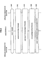
- FIG. 2 is a sequence diagram that shows the flow until the plurality of communication devices 20 set a direct link.
- a setting operation of a direct link setup (DLS) (hereinafter referred to as a unique DLS, which allows direct communication) that is not dependent on the base station 30 is started based on the generation of a start trigger (step S40).
- DLS direct link setup
- the wireless communication device 20A, the base station 30 and the wireless communication device 20B perform a unique DLS setting process (step S42).
- the unique DLS setting process is a series of frame exchange operations in which the wireless communication devices 20A and 20B transmit, receive and share information about their communication functions, capabilities and the like.
- the wireless communication device 20A, the base station 30 and the wireless communication device 20B perform a link quality measurement process (step S44).
- the link quality measurement process is a series of operations for obtaining information about a link quality of a direct link path between the wireless communication devices 20A and 20B, and about a link quality of a base station path between the wireless communication devices 20A and 20B via the base station 30.
- the path determination process is an operation to judge and determine which communication path, of the direct link path and the base station path, should be used for communication between the wireless communication devices 20A and 20B.
- the wireless communication device 20A and the wireless communication device 20B start communication using the communication path determined in the path determination process (step S48).
- the wireless communication system 1 according to the present embodiment has been outlined with reference to FIG. 1 and FIG. 2 .
- the background to create the wireless communication system 1 according to the present embodiment will be described.
- the wireless communication device 20A transmits to the base station 30 a data frame in accordance with a direct link protocol (DLP) method to inquire about the communication functions corresponding to the wireless communication device 20B.
- the base station 30 interprets the data frame, and transmits it to the wireless communication device 20B.
- the wireless communication device 20B interprets the data frame received from the wireless communication device 20A via the base station 30, and transmits to the base station 30 a data frame in response to the aforementioned data frame.
- the base station 30 interprets the data frame received from the wireless communication device 20B, and transmits it to the wireless communication device 20A.
- the wireless communication device 20A can perform the unique DLS setting process based on the data frame from the wireless communication device 20B received in this manner.
- the base station 30 cannot interpret the data frame transmitted from the wireless communication devices 20A and 20B. Therefore, there may be cases where the base station 30 cannot relay the data frame.
- the wireless communication system 1 has been created by focusing on the above-described circumstances.
- the wireless communication devices 20A and 20B can perform the unique DLS setting process, the link quality measurement process and the like, irrespective of whether or not the base station 30 is compatible with the DLP method.
- the wireless communication system 1, the wireless communication device 20A and the wireless communication device 20B that can perform the above will hereinafter be described in more detail.
- FIG. 3 is an explanatory diagram that shows a configuration of the wireless communication device 20 according to the present embodiment.
- the wireless communication device 20 includes an antenna 22, a data processing portion 216, a transmission processing portion 220, a wireless interface 224, a control portion 228, a dedicated relay data frame processing portion 236, and a measurement portion 240.
- the data processing portion 216 In transmission, the data processing portion 216 generates various types of data frames according to a request from, for example, a higher-level layer and supplies them to the transmission processing portion 220. Further, in reception, the data processing portion 216 processes and analyses the various types of data frames supplied from the transmission processing portion 220. Examples of the various types of data frames include: a management frame such as an association request, an association response, a probe request, a probe response, an authentication request, a deauthentication request, a reserve request and the like; a control frame such as request to send (RTS), clear to send (CTS), acknowledgment (ACK) and the like; and an arbitrary frame such as a frame including actual data.
- a management frame such as an association request, an association response, a probe request, a probe response, an authentication request, a deauthentication request, a reserve request and the like
- a control frame such as request to send (RTS), clear to send (CTS), acknowledgment (ACK) and the like
- an arbitrary frame
- the transmission processing portion 220 adds a header and an error detection code, such as a frame check sequence (FCS), to the various types of data frames supplied from the data processing portion 216, and supplies the data frames to the wireless interface 224. Further, in reception, the transmission processing portion 220 analyses the header added to each of the various types of data frames supplied from the wireless interface 224. When the transmission processing portion 220 confirms that there is no error in each data frame based on the error detection code, it supplies the various types of data frames to the data processing portion 216.
- the header may include frame control information, duration, TA, RA, SA, DA, sequence control information, and the like.
- the wireless interface 224 In transmission, the wireless interface 224 generates a modulation signal in a frequency band of a carrier wave based on the various types of data frames supplied from the transmission processing portion 220, and causes the antenna 22 to transmit the modulation signal as a wireless signal. Further, in reception, the wireless interface 224 decodes the various types of data frames, by down-converting the wireless signal received by the antenna 22 and converting it to a bit sequence. That is, the wireless interface 224 can serve as a transmitting portion and a receiving portion by cooperating with the antenna 22. Note that, although the single antenna 22 is shown in FIG. 3 , the wireless communication device 20 may include a plurality of the antennas 22 and may have a multiple input multiple output (MIMO) function.
- MIMO multiple input multiple output
- the control portion 228 controls various operations, such as a reception operation and a transmission operation, of the wireless communication device 20. Further, as described later, the control portion 228 has a function as a determination portion that determines, in the unique DLS setting process, whether or not the wireless communication device 20B is compatible with the unique DLS.
- the memory 232 serves as a data processing working area used by the control portion 228, and has a function as a storage medium storing various types of data.
- the memory 232 may be a storage medium such as: a non-volatile memory such as an electrically erasable programmable read only memory (EEPROM), an erasable programmable read only memory (EPROM) or the like; a magnetic disk such as a hard disk, a disc-shaped magnetic disk or the like; an optical disk such as a compact disc recordable (CD-R) / rewritable (RW), a digital versatile disc recordable (DVD-R) / RW / +R / +RW / a random access memory (RAM), a blu-ray disc (BD) (registered trade mark) -R / BD-RE; and a magneto optical (MO)disk.
- a non-volatile memory such as an electrically erasable programmable read only memory (EEPROM), an era
- the dedicated relay data frame processing portion 236 generates, processes and analyses a dedicated relay data frame as a specific data frame that is important in the present embodiment. A specific configuration of the dedicated relay data frame will be described with reference to FIG. 5 .
- the measurement portion 240 measures the link quality of a data frame received from the wireless communication device 20B via the direct link path, and the link quality of a data frame received via the base station path.
- the link quality measured by the measurement portion 240 may be stored in the memory 232.
- the link quality measured by the measurement portion 240 may be a received channel power indicator (RCPI) defined by IEEE802.11k, or may be a received signal strength indication (RSSI).
- RCPI received channel power indicator
- RSSI received signal strength indication
- the measurement portion 240 may measure the RCPI of a data frame whose TA is the address of the wireless communication device 20B that is transmitted from the wireless communication device 20B to the base station 30, in addition to the RCPI of a data frame whose TA is the address of the base station 30 that is transmitted from the base station 30.
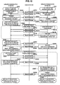
- FIG. 4 is a sequence diagram that shows the flow of the unique DLS setting process.
- the wireless communication device 20A proceeds to the unique DLS setting process (step S40).
- a specific content of the start trigger is not particularly limited, a timing when the machine (MAC) address of the communication target (the wireless communication device 20B) is obtained corresponds to the start trigger.
- the wireless communication devices 20A and 20B are compatible with a digital living network alliance (DLNA), device detection using a universal plug and play (UPnP) protocol, or occurrence of packet transmission/reception for service detection (SSDP M-SEARCH Req/Res packet, SSDP NOTIFY packet, HTTP get Req packet) can correspond to the start trigger.
- DLNA digital living network alliance
- UPF universal plug and play
- SSDP M-SEARCH Req/Res packet SSDP NOTIFY packet
- HTTP get Req packet can correspond to the start trigger.
- the device/service detection and the direct link setting can be performed at the same time.
- setup can be performed efficiently only with a device that requires the direct link setting.
- the wireless communication device 20A transmits a "unique DLS setting request" (a first data frame) to the wireless communication device 20B (step S304). More specifically, the unique DLS setting request frame is capsulated as a specific Ethertype data frame for the unique DLS.
- the "data frame that is capsulated as a specific Ethertype for the unique DLS” is referred to as a "dedicated relay data frame”.
- a frame configuration of a data frame will be described with reference to FIG. 5 .
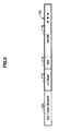
- FIG. 5 is an explanatory diagram that shows an example of a frame configuration of a data frame.
- the data frame includes an 802.11 MAC header 104, and a MAC service data unit (MSDU) 110.
- the 802.11 MAC header 104 includes a TA indicating the transmitter address of the data frame, an RA indicating the receiver address of the data frame, and the like.
- the 802.11 MAC header 104 includes the TA in which the address of the wireless communication device 20A is described, and the RA in which the address of the base station 30 is described, and the DA in which the address of the wireless communication device 20B is described.
- the MSDU 110 includes a logical link control subnetwork access protocol (LLCSNAP) 112, a type 114, and a payload 116.
- LLCSNAP logical link control subnetwork access protocol
- the LLCSNAP 112 is an 8 byte fixed pattern, and is provided for logical link control.
- the type 114 is information indicating a frame type of the data frame. For example, 2 byte information indicating that the data frame is a dedicated relay data frame is described in the type 114 of the dedicated relay data frame. Further, a message for direct link setting is described in the payload 116 of the dedicated relay data frame.
- the base station 30 receives the "unique DLS setting request".
- the "unique DLS setting request” includes an ID indicating that the content of the frame is the “unique DLS setting request”, the MAC addresses of the wireless communication devices 20A and 20B, BSSID, capability information of the wireless communication device 20A, and the like.
- the base station 30 that has received such a "unique DLS setting request” relays the "unique DLS setting request” to the wireless communication device 20B without regard to the content of the "unique DLS setting request” (step S308).
- the wireless communication device 20B When the wireless communication device 20B receives the "unique DLS setting request" from the wireless communication device 20A via the base station 30, it interprets the content of the "unique DLS setting request” from the Ethertype. When the wireless communication device 20B itself is compatible with the unique DLS and it can interpret the content of the "unique DLS setting request” (step S312), the wireless communication device 20B transmits a "unique DLS setting response" to the wireless communication device 20A (step S316).
- the "unique DLS setting response" (a second data frame) also includes an ID indicating that the content of the frame is the "unique DLS setting response", the MAC addresses of the wireless communication devices 20A and 20B, BSSID, capability information of the wireless communication device 20B, success and failure information, and the like. Note that when the wireless communication device 20B is not compatible with the unique DLS, the "unique DLS setting request" is treated as an unknown Ethertype frame. Therefore, the wireless communication device 20B cannot interpret the content of the frame, and the frame is cleared in the wireless communication device 20B.
- the base station 30 When the base station 30 receives the "unique DLS setting response" transmitted from the wireless communication device 20B, it relays the "unique DLS setting response" to the wireless communication device 20A without regard to the content of the "unique DLS setting response” (step S320).
- the wireless communication device 20A receives the "unique DLS setting response” from the wireless communication device 20B via the base station 30, it interprets the content thereof from the Ethertype (step S324).
- success and failure information of the "unique DLS setting response" indicates "success”
- the control portion 228 completes the setting of the unique DLS.
- the control portion 228 determines that the wireless communication device 20B is not compatible with the unique DLS, and a direct link is not established.
- the wireless communication devices 20A and 20B proceed to the link quality measurement process.
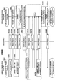
- FIG. 6 is a sequence diagram that shows the flow of a link quality measurement process according to the first operation example.
- the wireless communication device 20A uses the completion of the unique DLS setting process as a trigger, and immediately proceeds to a process to transmit a "direct link quality measurement request" to the wireless communication device 20B.
- data frames are transmitted and received via the base station 30 for security setting and the like, even after the setting of the unique DLS has been established. However, this process operates independently of them.
- the wireless communication device 20A transmits a "wake-up request", which is a dedicated relay data frame, to the wireless communication device 20B via the base station 30 (step S350 and step S352).
- a "wake-up request” which is a dedicated relay data frame
- the wireless communication device 20B can receive the "wake-up request” and interpret the content thereof, it transmits a "wake-up response" frame, which is a dedicated relay data frame, to the wireless communication device 20A (step S354 and step S356), and maintains an awake state for a certain time period in accordance with the "wake-up request".
- the wireless communication device 20A that has received the "wake-up response” and interpreted the content thereof transmits a "direct link transmission quality measurement request", which is a dedicated relay data frame, to the wireless communication device 20B via the base station 30 (step S358 and step S360).
- the content of the "direct link transmission quality measurement request” includes the MAC address of the base station 30 (BSSID) and the MAC address of the wireless communication device 20A.
- BSSID base station 30
- the wireless communication device 20B can receive and interpret the "direct link transmission quality measurement request", it transmits a "direct link transmission quality measurement response", which is a dedicated relay data frame, to the wireless communication device 20A via the base station 30 (step S362 and step S364).
- the "direct link transmission quality measurement response” includes information about whether or not the requested measurement is possible. Then, the wireless communication device 20B starts the measurement of the transmission quality of the wireless communication device 20A (step S366).
- the wireless communication device 20A starts to transmit probe frames to cause the wireless communication device 20B to measure the transmission quality (step S368).
- the wireless communication device 20A After the wireless communication device 20A has transmitted probe frames via the base station 30 over a predetermined period (or a specified number of times) (step S370 and step S372), it transmits probe frames directly to the wireless communication device 20B (step S374 and step S376).
- the wireless communication device 20A transmits probe frames including the RA in which the address of the base station 30 is described and the DA in which the address of the wireless communication device 20B is described.
- the wireless communication device 20A transmits probe frames including the RA in which the address of the wireless communication device 20B is described. Note that the payload of each probe frame may also include no information.
- the wireless communication device 20A transmits a "direct link transmission quality measurement completion", which is a dedicated relay data frame (step S378), and the base station 30 relays the "direct link transmission quality measurement completion" to the wireless communication device 20B (step S380).
- the wireless communication device 20B Until the wireless communication device 20B receives the "direct link transmission quality measurement completion" from the wireless communication device 20A, it receives the probe frames including the RA in which the address of the wireless communication device 20B is described (step S382). Then, for the frames whose TAs (transmitter addresses) are the address of the base station 30 (BSSID), and for the frames whose TAs are the address of the wireless communication device 20A (namely, traffic serving as a direct link path), the wireless communication device 20B measures received total channel power (RCPI) and the number of received packets, and stores the average value in the memory 232.
- the format of the RCPI may be the same as that defined by the 802.11k standard.
- the wireless communication device 20B that has completed the measurement of the probe frames transmits a "direct link transmission measurement report" frame, which is a dedicated relay data frame, to the wireless communication device 20A via the base station 30 as soon as preparation for the measurement report is completed (step S384 and step S386).
- the "direct link transmission measurement report” includes the MAC address of the base station 30, the average RCPI of the probe frames whose TAs are the address of the base station 30, the MAC address of the wireless communication device 20A, and the average RCPI of the probe frames whose TAs are the address of the wireless communication device 20A.
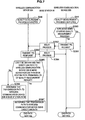
- FIG. 7 is a sequence diagram that shows the flow of the path determination process.
- the wireless communication device 20B that has measured the transmission quality of the wireless communication device 20A was in the PS mode before starting the measurement (step S390), it has already been forcibly awoken by the wireless communication device 20A.
- the wireless communication device 20B transmits a "PS notification", which is a dedicated relay data frame, to the wireless communication device 20A (step S391 and step S392).
- the wireless communication device 20A can receive and interpret the "PS notification", it knows that the wireless communication device 20B will return to the PS mode, and transmits a "PS confirmation", which is a dedicated relay data frame, to the wireless communication device 20B (step 393 and step S394).
- a "PS confirmation" which is a dedicated relay data frame
- the control portion 228 of the wireless communication device 20A determines, based on the above information, which path (i.e., either the base station path or the direct link path) to use for packet transmission from the wireless communication device 20A to the wireless communication device 20B (step S395). More specifically, the control portion 228 compares the RCPI of the direct link path with a threshold set in advance and with the RCPI of the base station path to evaluate the quality of the direct link, and determines whether to use the direct link.
- the wireless communication device 20A determines that the transmission path to the wireless communication device 20B is the base station path (step S396).
- the wireless communication device 20A determines that the transmission path to the wireless communication device 20B is the direct link path (step S397). Note that the wireless state can be roughly estimated from the number of frames that can be received through the direct link (the direct link from the wireless communication device 20A to the wireless communication device 20B).
- the first operation example of the wireless communication system 1 according to the present embodiment is described above.
- the wireless communication device 20A needs to transmit both the probe frames addressed to the base station 30 and the probe frames addressed to the wireless communication device 20B.
- a second operation example it is possible to eliminate the transmission process of the probe frames addressed to the wireless communication device 20B that is performed by the wireless communication device 20A.
- a link quality measurement process of the second operation example differs from that of the first operation example.
- the link quality measurement process according to the second operation example will be described with reference to FIG. 8 .
- FIG. 8 is a sequence diagram that shows the flow of the link quality measurement process according to the second operation example.
- the wireless communication device 20A transmits a "wake-up request", which is a dedicated relay data frame, to the wireless communication device 20B via the base station 30 (step S402 and step S404).
- a "wake-up request" which is a dedicated relay data frame
- the wireless communication device 20B can receive the "wake-up request” and interpret the content thereof, it transmits a "wake-up response" frame, which is a dedicated relay data frame, to the wireless communication device 20A (step S406 and step S408), and maintains an awake state for a certain time period in accordance with the "wake-up request".
- a "wake-up response" frame which is a dedicated relay data frame
- the wireless communication device 20A that has received the "wake-up response" and interpreted the content thereof transmits a "direct link transmission quality measurement request" frame, which is a dedicated relay data frame, to the wireless communication device 20B via the base station 30 (step S410 and step S412).
- the content of the "direct link transmission quality measurement request” includes the MAC address of the base station 30 (BSSID) and the MAC address of the wireless communication device 20A.
- BSSID MAC address of the base station 30
- the wireless communication device 20B can receive and interpret the "direct link transmission quality measurement request", it transmits a "direct link transmission quality measurement response", which is a dedicated relay data frame, to the wireless communication device 20A via the base station 30 (step S414 and step S416).
- the "direct link transmission quality measurement response” includes information about whether or not the requested measurement is possible. Then, the wireless communication device 20B starts the measurement of the transmission quality of the wireless communication device 20A (step S418).
- the wireless communication device 20B can receive both the probe frame transmitted from the base station 30 and the probe frame transmitted from the wireless communication device 20A. In other words, it is assumed that the wireless communication device 20B can receive the probe frame including the RA in which the address of the wireless communication device 20B is described, and the probe frame including the RA in which the address of the base station 30 is described. Further, it is assumed that the wireless communication device 20A has recognized the matter in the unique DLS setting process.
- the wireless communication device 20A starts to transmit a probe frame to cause the wireless communication device 20B to measure the transmission quality (step S420). More specifically, the wireless communication device 20A transmits a probe frame including the RA in which the address of the base station 30 is described, the TA in which the address of the wireless communication device 20A is described and the DA in which the address of the wireless communication device 20B is described, a specified number of times.
- the base station 30 changes the RA of each of the probe frames received from the wireless communication device 20A to the address of the wireless communication device 20B, changes the TA to the address of the base station 30, and transmits the probe frames (step S422 and step S424).
- the wireless communication device 20A transmits a "direct link transmission quality measurement completion", which is a dedicated relay data frame (step S426), and the base station 30 relays the "direct link transmission quality measurement completion" to the wireless communication device 20B (step S428).
- the wireless communication device 20B receives the "direct link transmission quality measurement completion" from the wireless communication device 20A, it receives the probe frames including the TA in which the address of the wireless communication device 20A is described that are transmitted from the wireless communication device 20A, in addition to the probe frames including the RA in which the address of the wireless communication device 20B is described that are transmitted from the base station 30 (step S430). Then, for the probe frames transmitted from the base station 30 and for the probe frames transmitted from the wireless communication device 20A, the wireless communication device 20B measures received total channel power (RCPI) and the number of received packets, and stores the average value in the memory 232.
- the format of the RCPI may be the same as that defined by the 802.11k standard.
- the wireless communication device 20B that has completed the measurement of the probe frames transmits a "direct link transmission measurement report" frame, which is a dedicated relay data frame, to the wireless communication device 20A via the base station 30 as soon as preparation for the measurement report is completed (step S432 and step S434).
- the "direct link transmission measurement report” includes the MAC address of the base station 30, the average RCPI of the probe frames whose TAs are the address of the base station 30, the MAC address of the wireless communication device 20A, and the average RCPI of the probe frames whose TAs are the address of the wireless communication device 20A.
- the second operation example of the wireless communication system 1 according to the present embodiment is described above.
- the wireless communication device 20B measures the quality of the probe frames transmitted from the wireless communication device 20A that independently performs the path determination process.
- a third operation example differs in that the wireless communication device 20B transmits probe frames, and the wireless communication device 20A measures the quality of the probe frames.
- the third operation example will be described with reference to FIG. 9 .
- FIG. 9 is a sequence diagram that shows the flow of a link quality measurement process according to the third operation example.
- the wireless communication device 20A first, taking into consideration a case where the wireless communication device 20B that is expected to measure link quality is in a power save (PS) mode, the wireless communication device 20A transmits a "wake-up request", which is a dedicated relay data frame, to the wireless communication device 20B via the base station 30 (step S502 and step S504).
- PS power save
- the wireless communication device 20B can receive the "wake-up request” and interpret the content thereof, it transmits a "wake-up response" frame, which is a dedicated relay data frame, to the wireless communication device 20A (step S506 and step S508), and maintains an awake state for a certain time period in accordance with the "wake-up request".
- a "wake-up response" frame which is a dedicated relay data frame
- the wireless communication device 20A that has received the "wake-up response” and interpreted the content thereof transmits a "direct link reception quality measurement request" frame, which is a dedicated relay data frame, to the wireless communication device 20B via the base station 30 (step S510 and step S512).
- the content of the "direct link reception quality measurement request” includes the MAC address of the base station 30 (BSSID) and the MAC address of the wireless communication device 20A.
- BSSID MAC address of the base station 30
- the wireless communication device 20B can receive and interpret the "direct link reception quality measurement request", it transmits a "direct link reception quality measurement response", which is a dedicated relay data frame, to the wireless communication device 20A via the base station 30 (step S514 and step S516).
- the "direct link reception quality measurement response" includes information about whether or not the requested measurement is possible.
- the wireless communication device 20A starts the measurement of the reception quality of the wireless communication device 20A (step S520).
- the wireless communication device 20B starts to transmit a probe frame to cause the wireless communication device 20A to measure the reception quality (step S522).
- the wireless communication device 20B After the wireless communication device 20B has transmitted probe frames via the base station 30 over a predetermined period (or a specified number of times) (step S524 and step S526), it transmits probe frames directly to the wireless communication device 20A (step S528 and step S530).
- the wireless communication device 20B After the wireless communication device 20B has transmitted probe frames including the RA in which the address of the base station 30 is described and the DA in which the address of the wireless communication device 20A is described, it transmits probe frames including the RA in which the address of the wireless communication device 20A is described.
- the wireless communication device 20B transmits a "direct link reception quality measurement completion", which is a dedicated relay data frame (step S532), and the base station 30 relays the "direct link reception quality measurement completion" to the wireless communication device 20A (step S534).
- the wireless communication device 20A receives the "direct link reception quality measurement completion" from the wireless communication device 20B, it receives the probe frames including the RA in which the address of the wireless communication device 20A is described (step S536). Then, for the frames whose TAs (transmitter addresses) are the address of the base station 30 (BSSID), and for the frames whose TAs are the address of the wireless communication device 20B (namely, traffic serving as a direct link path), the wireless communication device 20A measures received total channel power (RCPI) and the number of received packets, and stores the average value in the memory 232.
- the format of the RCPI may be the same as that defined by the 802.11k standard. Then, the wireless communication device 20A shifts from the link quality measurement process to the path determination process.
- the third operation example of the wireless communication system 1 according to the present embodiment is described above.
- probe frames are transmitted only in one direction, either from the wireless communication device 20A to the wireless communication device 20B, or from the wireless communication device 20B to the wireless communication device 20A.
- the wireless communication device 20A and the wireless communication device 20B can transmit probe frames bidirectionally, and bidirectional link quality can be obtained. As a result, a communication path can be determined more appropriately.
- the fourth operation example will be described with reference to FIG. 10 .
- FIG. 10 is a sequence diagram that shows the flow of a link quality measurement process according to the fourth operation example.
- the wireless communication device 20A first, taking into consideration a case where the wireless communication device 20B that is expected to measure link quality is in a power save (PS) mode, the wireless communication device 20A transmits a "wake-up request", which is a dedicated relay data frame, to the wireless communication device 20B via the base station 30 (step S552 and step S554).
- PS power save
- the wireless communication device 20B can receive the "wake-up request” and interpret the content thereof, it transmits a "wake-up response" frame, which is a dedicated relay data frame, to the wireless communication device 20A (step S556 and step S558), and maintains an awake state for a certain time period according to the "wake-up request".
- a "wake-up response" frame which is a dedicated relay data frame
- the wireless communication device 20A that has received the "wake-up response” and interpreted the content thereof transmits a "direct link reception quality measurement request" frame, which is a dedicated relay data frame, to the wireless communication device 20B via the base station 30 (step 560 and step S562).
- the content of the "direct link reception quality measurement request” includes the MAC address of the base station 30 (BSSID) and the MAC address of the wireless communication device 20A.
- BSSID MAC address of the base station 30
- the wireless communication device 20B can receive and interpret the "direct link reception quality measurement request", it transmits a "direct link reception quality measurement response", which is a dedicated relay data frame, to the wireless communication device 20A via the base station 30 (step S564 and step S566).
- the "direct link reception quality measurement response" includes information about whether or not the requested measurement is possible.
- the wireless communication device 20A starts the measurement of the reception quality of the wireless communication device 20A (step S568).
- the wireless communication device 20B starts to transmit a probe frame to cause the wireless communication device 20A to measure the reception quality (step S570). More specifically, the wireless communication device 20B transmits probe frames including the RA in which the address of the base station 30 is described and the DA in which the address of the wireless communication device 20A is described.
- the base station 30 changes the TA of each of the probe frames received from the wireless communication device 20B to the address of the base station 30 and changes the RA to the address of the wireless communication device 20A, and transmits the probe frames (step S572 and step S574).
- the wireless communication device 20B transmits a "direct link reception quality measurement completion", which is a dedicated relay data frame (step S576), and the base station 30 relays the "direct link reception quality measurement completion" to the wireless communication device 20A (step S578).
- the wireless communication device 20A receives the "direct link reception quality measurement completion" from the wireless communication device 20B, it receives both the probe frames including the RA in which the address of the wireless communication device 20A is described and the probe frames including the TA in which the address of the wireless communication device 20B is described (step S580). Then, for the frames whose TAs (transmitter addresses) are the address of the base station 30 (BSSID), and for the frames whose TAs are the address of the wireless communication device 20B (namely, traffic serving as a direct link path), the wireless communication device 20A measures received total channel power (RCPI) and the number of received packets, and stores the average value in the memory 232.
- RCPI received total channel power
- the wireless communication device 20A transmits a "direct link transmission quality measurement request" frame, which is a dedicated relay data frame, to the wireless communication device 20B via the base station 30 (step S582 and step S584).
- the content of the "direct link transmission quality measurement request” includes the MAC address of the base station 30 (BSSID) and the MAC address of the wireless communication device 20A.
- BSSID base station 30
- the wireless communication device 20B can receive and interpret the "direct link transmission quality measurement request", it transmits a "direct link transmission quality measurement response", which is a dedicated relay data frame, to the wireless communication device 20A via the base station 30 (step S586 and step S588).
- the "direct link transmission quality measurement response" includes information about whether or not the requested measurement is possible.
- the wireless communication device 20B starts the measurement of the transmission quality of the wireless communication device 20A (step S590).
- the wireless communication device 20B can receive both the probe frame transmitted from the base station 30 and the probe frame transmitted from the wireless communication device 20A. In other words, it is assumed that the wireless communication device 20B can receive the probe frame including the RA in which the address of the wireless communication device 20B is described, and the probe frame including the RA in which the address of the base station 30 is described. Further, it is assumed that the wireless communication device 20A has recognized the matter in the unique DLS setting process.
- the wireless communication device 20A starts to transmit a probe frame to cause the wireless communication device 20B to measure the transmission quality (step S591). More specifically, the wireless communication device 20A transmits probe frames including the RA in which the address of the base station 30 is described, the TA in which the address of the wireless communication device 20A is described, and the DA in which the address of the wireless communication device 20B is described, a specified number of times.
- the base station 30 changes the RA of each of the probe frames received from the wireless communication device 20A to the address of the wireless communication device 20B, changes the TA to the address of the base station 30, and transmits the probe frames (step S592, step S593 and step S594).
- the wireless communication device 20A transmits a "direct link transmission quality measurement completion", which is a dedicated relay data frame (step S595), and the base station 30 relays the "direct link transmission quality measurement completion" to the wireless communication device 20B (step S596).
- the wireless communication device 20B receives the "direct link transmission quality measurement completion" from the wireless communication device 20A, it receives the probe frames including the TA in which the address of the wireless communication device 20A is described that are transmitted from the wireless communication device 20A, in addition to the probe frames including the RA in which the address of the wireless communication device 20B is described that are transmitted from the base station 30 (step S597). Then, for the probe frames transmitted from the base station 30 and for the probe frames transmitted from the wireless communication device 20A, the wireless communication device 20B measures received total channel power (RCPI) and the number of received packets, and stores the average value in the memory 232.
- the format of the RCPI may be the same as that defined by the 802.11k standard.
- the wireless communication device 20B that has completed the measurement of the probe frames transmits a "direct link transmission measurement report" frame, which is a dedicated relay data frame, to the wireless communication device 20A via the base station 30 as soon as preparation for the measurement report is completed (step S598 and step S599).
- the "direct link transmission measurement report” includes the MAC address of the base station 30, the average RCPI of the probe frames whose TAs are the address of the base station 30, the MAC address of the wireless communication device 20A, and the average RCPI of the probe frames whose TAs are the address of the wireless communication device 20A.
- the flow of the path determination process according to the fourth operation example is common to that of the first operation example.
- the wireless communication device 20A when the link quality measurement process is completed, the wireless communication device 20A has already obtained information about the RCPI of the base station path from the base station 30 to the wireless communication device 20A and the RCPI of the direct link path from the wireless communication device 20B to the wireless communication device 20A, in addition to information about the RCPI of the base station path from the base station 30 to the wireless communication device 20B and the RCPI of the direct link path from the wireless communication device 20A to the wireless communication device 20B. Therefore, the wireless communication device 20A can determine whether to use the base station path or the direct link path, based on the above information. For example, the wireless communication device 20A may set the communication path by calculating a difference in bilateral RCPI and taking a difference in the absolute transmission power into consideration.
- the fourth operation example of the wireless communication system 1 according to the present embodiment is described above.
- frame quality measurement is started after the "direct link reception quality measurement request" or the "direct link transmission quality measurement request”.
- a fifth operation example differs in that the frame quality measurement is started at an earlier timing.
- the fifth operation example will be described with reference to FIG. 11 .
- FIG. 11 is a sequence diagram that shows the fifth operation example of the wireless communication system 1.
- the wireless communication device 20A transmits a "unique DLS setting request", which is a dedicated relay data frame, to the wireless communication device 20B (step S602). More specifically, the unique DLS setting request frame is capsulated as a specific Ethertype data frame for the unique DLS.
- the base station 30 receives the "unique DLS setting request".
- the "unique DLS setting request” includes an ID indicating that the content of the frame is the “unique DLS setting request”, the MAC addresses of the wireless communication devices 20A and 20B, the BSSID, capability information of the wireless communication device 20A, and the like.
- the base station 30 that has received such a "unique DLS setting request” relays the "unique DLS setting request” to the wireless communication device 20B without regard to the content of the "unique DLS setting request” (step S604).
- the wireless communication device 20B When the wireless communication device 20B receives the "unique DLS setting request" from the wireless communication device 20A via the base station 30, it interprets the content of the "unique DLS setting request” from the Ethertype.
- the wireless communication device 20B itself is compatible with the unique DLS and it can interpret the content of the "unique DLS setting request” (step S606), the wireless communication device 20B starts to measure the transmission quality of the wireless communication device 20A (step S610). Meanwhile, the wireless communication device 20A that has transmitted the "unique DLS setting request" starts to measure the reception quality of the wireless communication device 20A (step S608). That is, in the fifth operation example, the "unique DLS setting request" has part of the function of "the direct link reception quality measurement request" or the "the direct link transmission quality measurement request” in the first to fourth operation examples.
- the wireless communication device 20B transmits a "unique DLS setting response" to the wireless communication device 20A (step S612).
- the "unique DLS setting response” also includes an ID indicating that the content of the frame is the “unique DLS setting response”, the MAC addresses of the wireless communication devices 20A and 20B, the BSSID, capability information of the wireless communication device 20B, success and failure information, and the like. Note that when the wireless communication device 20B is not compatible with the unique DLS, the "unique DLS setting request" is treated as an unknown Ethertype frame. Therefore, the wireless communication device 20B cannot interpret the content of the frame, and the frame is cleared in the wireless communication device 20B.
- the base station 30 When the base station 30 receives the "unique DLS setting response" transmitted from the wireless communication device 20B, it relays the "unique DLS setting response" to the wireless communication device 20A without regard to the content of the "unique DLS setting response” (step S614).
- the wireless communication device 20A receives the "unique DLS setting response” from the wireless communication device 20B via the base station 30, it interprets the content thereof from the Ethertype (step S616).
- success and failure information of the "unique DLS setting response" indicates “success”
- the control portion 228 completes the setting of the unique DLS (step S618).
- the control portion 228 determines that the wireless communication device 20B is not compatible with the unique DLS, and a direct link is not established.
- the wireless communication device 20A transmits a "wake-up request", which is a dedicated relay data frame, to the wireless communication device 20B via the base station 30 (step S620 and step S622).
- a "wake-up request” which is a dedicated relay data frame
- the wireless communication device 20B can receive the "wake-up request” and interpret the content thereof, it transmits a "wake-up response" frame, which is a dedicated relay data frame, to the wireless communication device 20A (step S624 and step S626), and maintains an awake state for a certain time period in accordance with the "wake-up request".
- the wireless communication device 20A that has received the "wake-up response” and interpreted the content thereof transmits a "direct link reception quality measurement request" frame, which is a dedicated relay data frame, to the wireless communication device 20B via the base station 30 (step S628 and step S630).
- the content of the "direct link reception quality measurement request” includes the MAC address of the base station 30 (BSSID) and the MAC address of the wireless communication device 20A.
- BSSID MAC address of the base station 30
- the wireless communication device 20B can receive and interpret the "direct link reception quality measurement request", it transmits a "direct link reception quality measurement response", which is a dedicated relay data frame, to the wireless communication device 20A via the base station 30 (step S632 and step S633).
- the "direct link reception quality measurement response" includes information about whether or not the requested measurement is possible.
- the wireless communication device 20B starts to transmit a probe frame to cause the wireless communication device 20A to measure the reception quality (step S634). More specifically, the wireless communication device 20B transmits probe frames including the RA in which the address of the base station 30 is described and the DA in which the address of the wireless communication device 20A is described. The base station 30 changes the TA of each of the probe frames received from the wireless communication device 20B to the address of the base station 30 and changes the RA to the address of the wireless communication device 20A, and transmits the probe frames (step S636 and step S638).
- the wireless communication device 20B transmits a "direct link reception quality measurement completion", which is a dedicated relay data frame (step S642), and the base station 30 relays the "direct link reception quality measurement completion" to the wireless communication device 20A (step S644).
- the wireless communication device 20A receives the "direct link reception quality measurement completion" from the wireless communication device 20B, it receives both the probe frames including the RA in which the address of the wireless communication device 20A is described and the probe frames including the TA in which the address of the wireless communication device 20B is described (step S580). Then, for the frames whose TAs (transmitter addresses) are the address of the base station 30 (BSSID), and for the frames whose TAs are the address of the wireless communication device 20B (namely, traffic serving as a direct link path), the wireless communication device 20A measures received total channel power (RCPI) and the number of received packets, and stores the average value in the memory 232.
- RCPI received total channel power
- the wireless communication device 20A transmits a "direct link transmission quality measurement request" frame, which is a dedicated relay data frame, to the wireless communication device 20B via the base station 30 (step S646 and step S648).
- the content of the "direct link transmission quality measurement request” includes the MAC address of the base station 30 (BSSID) and the MAC address of the wireless communication device 20A.
- the wireless communication device 20B can receive and interpret the "direct link transmission quality measurement request", it transmits a "direct link transmission quality measurement response", which is a dedicated relay data frame, to the wireless communication device 20A via the base station 30 (step S650 and step S652).
- the "direct link transmission quality measurement response" includes information about whether or not the requested measurement is possible.
- the wireless communication device 20B can receive both the probe frame transmitted from the base station 30 and the probe frame transmitted from the wireless communication device 20A. In other words, it is assumed that the wireless communication device 20B can receive the probe frame including the RA in which the address of the wireless communication device 20B is described, and the probe frame including the RA in which the address of the base station 30 is described. Further, it is assumed that the wireless communication device 20A has recognized the matter in the unique DLS setting process.
- the wireless communication device 20A starts to transmit a probe frame to cause the wireless communication device 20B to measure the transmission quality (step S654). More specifically, the wireless communication device 20A transmits a probe frame including the RA in which the address of the base station 30 is described, the TA in which the address of the wireless communication device 20A is described, and the DA in which the address of the wireless communication device 20B is described, a specified number of times.
- the base station 30 changes the RA of each of the probe frames received from the wireless communication device 20A to the address of the wireless communication device 20B, changes the TA to the address of the base station 30, and transmits the probe frames (step S656 and step 658).
- the wireless communication device 20A transmits a "direct link transmission quality measurement completion", which is a dedicated relay data frame (step S662), and the base station 30 relays the "direct link transmission quality measurement completion" to the wireless communication device 20B (step S663).
- the wireless communication device 20B receives the "direct link transmission quality measurement completion" from the wireless communication device 20A, it receives the probe frames including the TA in which the address of the wireless communication device 20A is described that are transmitted from the wireless communication device 20A, in addition to the probe frames including the RA in which the address of the wireless communication device 20B is described that are transmitted from the base station 30 (step S664). Then, for the probe frames transmitted from the base station 30 and for the probe frames transmitted from the wireless communication device 20A, the wireless communication device 20B measures received total channel power (RCPI) and the number of received packets, and stores the average value in the memory 232.
- the format of the RCPI may be the same as that defined by the 802.11k standard.
- the wireless communication device 20B that has completed the measurement of the probe frames transmits a "direct link transmission measurement report" frame, which is a dedicated relay data frame, to the wireless communication device 20A via the base station 30 as soon as preparation for the measurement report is completed (step S666 and step S668).
- the "direct link transmission measurement report” includes the MAC address of the base station 30, the average RCPI of the probe frames whose TAs are the address of the base station 30, the MAC address of the wireless communication device 20A, and the average RCPI of the probe frames whose TAs are the address of the wireless communication device 20A. Then, the wireless communication device 20A ends the reception quality measurement of the wireless communication device 20A, and proceeds to a path determination process.
- the wireless communication device 20A immediately ends the reception quality measurement.
- the path determination process of the fifth operation example can be performed in substantially the same manner as that of the fourth operation example, and therefore, a description thereof will be omitted.
- a dedicated relay data frame such as the "direct link reception quality measurement request" and the "direct link transmission quality measurement request" can also be used as a sample for quality measurement.
- the wireless communication device 20A can appropriately determine a communication path based on more information.
- the base station 30 relays the "unique DLS setting request" and the "unique DLS setting response" between the wireless communication devices 20A and 20B.
- the wireless communication device 20B receives a "unique DLS setting request” that is a dedicated relay data frame relayed by the base station 30, if the wireless communication device 20B is compatible with a direct link, it transmits a "unique DLS setting response" that is a dedicated relay data frame.
- the wireless communication device 20A can determine that the wireless communication device 20B is compatible with the direct link, based on the fact that it has received the "unique DLS setting response" that is a dedicated relay data frame relayed by the base station 30. That is, even when the base station 30 cannot interpret the contents of the "unique DLS setting request" and the "unique DLS setting response" that are dedicated relay data frames, the wireless communication device 20A can confirm whether or not the wireless communication device 20B is compatible with the direct link. Then, by way of the link quality measurement process and the path determination process, it is possible to communicate using either the base station path or the direct link path.
- the respective processing steps of the wireless communication system 1 may include processing that is performed in parallel or separately (for example, parallel processing or object processing).
Landscapes
- Engineering & Computer Science (AREA)
- Computer Networks & Wireless Communication (AREA)
- Signal Processing (AREA)
- Mobile Radio Communication Systems (AREA)
- Small-Scale Networks (AREA)
Abstract
Description
- The present invention contains subject matter related to Japanese Patent Application
JP 2007-334205 - The present invention relates to a wireless communication system, a wireless communication device, a wireless communication method, and a program.
- Recently, local area network (LAN) standards such as IEEE802.11a and IEEE802.11b have been established. These LAN standards define an infrastructure mode and an ad hoc mode. In the infrastructure mode, an access point (base station) adjusts access timing of a plurality of wireless communication devices. In the ad hoc mode, access timing is determined between wireless terminal devices.
- The infrastructure mode in which communication is performed via an access point is disadvantageous in that throughput decreases in comparison with the ad-hoc mode, but it is advantageous in that managed wireless communication devices can access a wired LAN and the Internet. In the ad-hoc mode, wireless communication devices directly communicate with each other, and there is therefore no overhead due to access point relay, and throughput increases. However, the ad-hoc mode is disadvantageous in that a wired LAN and the Internet cannot be accessed.
- As a method to exploit the advantages of both modes, a direct link protocol (DLP) method is defined as an optional function of 802.11e. According to the DLP method, wireless communication devices can directly communicate with each other by setting a direct link (direct communication link) while maintaining the infrastructure mode.
- For example, Japanese Patent Application Publication No.
JP-A-2003-348103 JP-A-2003-348103 - When an access point (base station) is compatible with the DLP method, the known wireless communication device can confirm whether or not another wireless communication device is compatible with the DLP method via the access point. However, when the access point is not compatible with the DLP method, the known wireless communication device cannot use the DLP method.
- The present invention addresses the problem described above and provides a wireless communication system, a wireless communication device, a wireless communication method, and a program that are new and improved and that are capable of determining whether or not another wireless communication device is capable of direct communication, irrespective of a function of a base station.
- According to an embodiment of the present invention, there is provided a wireless communication system that includes a first wireless communication device, a second wireless communication device, and a base station that relays wireless communication between the first and the second wireless communication devices. The first wireless communication device is capable of direct communication with another wireless communication device, and transmits a first data frame of a particular frame type to the second wireless communication device via the base station. If the second wireless communication device is capable of the direct communication, when receiving the first data frame of the particular frame type, the second wireless communication device transmits a second data frame of the particular frame type via the base station. When the first wireless communication device receives the second data frame from the second wireless communication device, the first wireless communication device determines that the second wireless communication device is capable of the direct communication.
- In the above-described configuration, irrespective of whether or not a first data frame and a second data frame of a particular frame type are frames to establish direct communication, the base station relays the first data frame and the second data frame between the first and second wireless communication devices. When the second wireless communication device receives the first data frame of the particular frame type relayed by the base station, if the second wireless communication device is capable of direct communication, it transmits the second data frame of the particular frame type. Further, the first wireless communication device can determine that the second wireless communication device is capable of direct communication, based on the fact that it has received the second data frame of the particular frame type relayed by the base station. That is, even when the base station cannot interpret the contents of the first and second data frames of the particular frame type, the first wireless communication device can confirm whether or not the second wireless communication device is capable of direct communication.
- When the first wireless communication device determines that the second wireless communication device is capable of the direct communication, the first wireless communication device may transmit a predetermined data frame. When the base station receives the predetermined data frame from the first wireless communication device, the base station may transmit the predetermined data frame to the second wireless communication device. The second wireless communication device may measure signal quality of both the predetermined data frame transmitted from the first wireless communication device and the predetermined data frame transmitted from the base station, and may transmit the measured signal quality to the first wireless communication device.
- In the above-described configuration, when the first wireless communication device transmits a predetermined data frame via the base station, the second wireless communication device can receive the data frame transmitted from the first wireless communication device, in addition to the data frame relayed by the base station, and can measure the signal quality of both data frames. Therefore, if the first wireless communication device transmits the predetermined data frame via the base station, the second wireless communication device can measure the signal quality of both data frames, without direct data frame transmission to the second wireless communication device. As a result, a transmission processing load on the first wireless communication device can be reduced. In addition, the amount of traffic can be reduced, leading to effective use of a bandwidth.
- The first wireless communication device may determine, based on the signal quality transmitted from the second wireless communication device, whether to communicate with the second wireless communication device via the base station or to perform the direct communication. For example, the first wireless communication device can perform communication via the base station or direct communication, whichever provides better signal quality.
- When the first wireless communication device determines that the second wireless communication device is capable of the direct communication, the first wireless communication device may transmit a predetermined data frame to the second wireless communication device via the base station, and also transmit the predetermined data frame to the second wireless communication device directly. The second wireless communication device may sequentially measure signal quality of both the predetermined data frame directly received from the first wireless communication device and the predetermined data frame received from the base station, and transmit the measured signal quality to the first wireless communication device. In this configuration, even when the second wireless communication device cannot directly receive from the first wireless communication device the data frame transmitted from the first wireless communication device via the base station, the second wireless communication device can measure the signal quality of both the data frame transmitted from the first wireless communication device and the data frame transmitted from the base station.
- When the first wireless communication device determines that the second wireless communication device is capable of the direct communication, the first wireless communication device may transmit a third data frame of the particular frame type to the second wireless communication device. When the second wireless communication device receives the third data frame from the first wireless communication device, the second wireless communication device may transmit a predetermined data frame to the first wireless communication device via the base station. In this configuration, the first wireless communication device can measure the signal quality of the data frame transmitted from the second wireless communication device to the first wireless communication device.
- The second wireless communication device may further transmit the predetermined data frame to the first wireless communication device directly.
- When the second wireless communication device receives the first data frame from the first wireless communication device, the second wireless communication device may measure signal quality of subsequently transmitted data frames. In this configuration, when the first wireless communication device transmits a data frame before transmitting a predetermined data frame, the second wireless communication device can also regard the predetermined data frame as a target for signal quality measurement.
- When the first wireless communication device transmits the first data frame, the first wireless communication device may measure signal quality of subsequently transmitted data frames. In this configuration, when the second wireless communication device transmits a data frame before transmitting a predetermined data frame, the first wireless communication device can also regard the predetermined data frame as a target for signal quality measurement.
- When the base station receives a data frame from one of the first wireless communication device and the second wireless communication device, the base station may transmit the data frame to a destination wireless communication device without regard to whether the data frame is of the particular frame type.
- When the first wireless communication device confirms presence of the second wireless communication device based on a universal plug and play (UPnP) protocol, the first wireless communication device may transmit the first data frame.
- According to another embodiment of the present invention, there is provided a wireless communication device capable of communication with another wireless communication device via a base station, including: a transmitting portion that transmits a first data frame of a particular frame type to the other wireless communication device via the base station; a receiving portion that, when the other wireless communication device has a direct communication function with the wireless communication device, receives a second data frame of the particular frame type that is transmitted from the other wireless communication device in response to the first data frame; and a determination portion that, when the receiving portion receives the second data frame from the other wireless communication device, determines that the other wireless communication device has the direct communication function.
- According to another embodiment of the present invention, there is provided a wireless communication device capable of communication with another wireless communication device via a base station, including: a receiving portion that receives a first data frame of a particular frame type from the other wireless communication device; and a transmitting portion that, when the wireless communication device has a direct communication function with the other wireless communication device, transmits a second data frame of the particular frame type in response to the first data frame.
- According to another embodiment of the present invention, there is provided a wireless communication method performed in a wireless communication system that includes a first wireless communication device, a second wireless communication device, and a base station that relays wireless communication between the first and the second wireless communication devices. The wireless communication method includes the steps of: transmitting a first data frame of a particular frame type from the first wireless communication device capable of direct communication with another wireless communication device to the second wireless communication device via the base station; receiving the first data frame by the second wireless communication device; transmitting a second data frame of the particular frame type from the second wireless communication device when the second wireless communication device is capable of the direct communication; receiving the second data frame by the first wireless communication device; and determining, by the first communication device, that the second wireless communication device is capable of the direct communication.
- According to another embodiment of the present invention, there is provided a program including instructions that command a computer, provided in a wireless communication device capable of communication with another wireless communication device via a base station, to function as a control portion executing the steps of: causing a transmitting device to transmit a first data frame of a particular frame type to the other wireless communication device via the base station; causing a receiving device to receive a second data frame of the particular frame type that is transmitted from the other wireless communication device in response to the first data frame when the other wireless communication device has a direct communication function with the wireless communication device; and determining, when the receiving device receives the second data frame from the other wireless communication device, that the other wireless communication device has the direct communication function.
- The above-described program can cause a hardware resource of a computer including, for example, a CPU, a ROM and a RAM to execute the function of the control portion as described above. That is, a computer that uses the program can be caused to function as the above-described control portion.
- According to the embodiments of the present invention described above, whether or not another wireless communication device is capable of direct communication can be determined irrespective of the function of a base station.
-
-
FIG. 1 is an explanatory diagram that shows a configuration of a wireless communication system according to an embodiment of the present invention; -
FIG. 2 is a sequence diagram that shows the flow until a plurality of communication devices set a direct link; -
FIG. 3 is an explanatory diagram that shows a configuration of a wireless communication device according to the embodiment; -
FIG. 4 is a sequence diagram that shows the flow of a unique direct link setup (DLS) setting process; -
FIG. 5 is an explanatory diagram that shows an example of a frame configuration of a data frame; -
FIG. 6 is a sequence diagram that shows the flow of a link quality measurement process according to a first operation example; -
FIG. 7 is a sequence diagram that shows the flow of a path determination process; -
FIG. 8 is a sequence diagram that shows the flow of a link quality measurement process according to a second operation example; -
FIG. 9 is a sequence diagram that shows the flow of a link quality measurement process according to a third operation example; -
FIG. 10 is a sequence diagram that shows the flow of a link quality measurement process according to a fourth operation example; and -
FIG. 11 is a sequence diagram that shows a fifth operation example of awireless communication system 1. - Hereinafter, preferred embodiments of the present invention will be described in detail with reference to the appended drawings. Note that, in this specification and the appended drawings, structural elements that have substantially the same function and structure are denoted with the same reference numerals, and repeated explanation of these structural elements is omitted.
- The preferred embodiment sfor practicing the present invention will be explained in the order shown below.
- 1. Overview of wireless communication system according to the present embodiment
- 2. Background of the present embodiment
- 3. Configuration of wireless communication device
- 4. Operation of the wireless communication system
- 4-1. First operation example
- 4-2. Second operation example
- 4-3. Third operation example
- 4-4. Fourth operation example
- 4-5. Fifth operation example
- 5. Conclusion
- First, an overview of a
wireless communication system 1 according to the present embodiment will be explained with reference toFIG. 1 . -
FIG. 1 is an explanatory diagram that shows a configuration of thewireless communication system 1 according to the present embodiment. As shown inFIG. 1 , thewireless communication system 1 includes awireless communication device 20A, awireless communication device 20B, abase station 30, and aLAN 32. - The
base station 30 manages thewireless communication device 20A and thewireless communication device 20B that are present within a radio wave reachable range of thebase station 30. Further, thebase station 30 is connected to theLAN 32 that functions as a backbone network such as Ethernet (registered trademark). When theLAN 32 and thewireless communication device 20A or thewireless communication device 20B communicate, thebase station 30 relays communication between theLAN 32 and thewireless communication device 20A or thewireless communication device 20B. - Further, the
base station 30 controls communication performed by the managedwireless communication device 20A andwireless communication device 20B. For example, thebase station 30 periodically transmits a beacon, which is a communication control signal, and thewireless communication device 20A and thewireless communication device 20B receive the beacon, thereby sharing timing in thewireless communication system 1. - In addition, when the
base station 30 receives a data frame addressed to thewireless communication device 20B that is transmitted from thewireless communication device 20A, thebase station 30 transmits the received data frame to thewireless communication device 20B. More specifically, the address of thewireless communication device 20A is described in a transmitter address (TA) of the data frame addressed to thewireless communication device 20B that is transmitted from thewireless communication device 20A. The address of thebase station 30 is described in a receiver address (RA), and the address of thewireless communication device 20B is described in a destination address (DA). When thebase station 30 receives the data frame, it changes the RA to the address of thewireless communication device 20B that has been described in the DA, describes in a source address (SA) the address of thewireless communication device 20A that has been described in the TA, changes the TA to the address of thebase station 30, and transmits the data frame. Thus, thewireless communication device 20B can receive the data frame in which the address of the own device is described in the RA. - Note that, in
FIG. 1 , portable game consoles are shown as an example of thewireless communication devices wireless communication devices wireless communication devices wireless communication device 20 may include audio data such as music, a lecture, a radio program or the like, visual data such as a motion picture, a television program, a video program, a photograph, a document, a painting, a diagram or the like, and any other type of data such as a game, software or the like. Note that, inFIG. 1 , in order to distinguish the respective wireless communication devices, a capital letter of the alphabet is added after each reference numeral, such as for thewireless communication devices wireless communication devices 20. - In
FIG. 1 , thewireless communication devices wireless communication devices 20 managed by thesingle base station 30. However, thesingle base station 30 may manage three or morewireless communication devices 20. Further, theLAN 32 is shown as an example of a communication network inFIG. 1 . Other examples of the communication network include a leased line network such as a wide area network (WAN), an internet protocol-virtual private network (IP-VPN), and the like. - In the above-described
wireless communication system 1, in addition to wireless communication via thebase station 30, thewireless communication devices wireless communication devices FIG. 2 . -
FIG. 2 is a sequence diagram that shows the flow until the plurality ofcommunication devices 20 set a direct link. First, when thewireless communication devices base station 30 is started based on the generation of a start trigger (step S40). - Then, the
wireless communication device 20A, thebase station 30 and thewireless communication device 20B perform a unique DLS setting process (step S42). The unique DLS setting process is a series of frame exchange operations in which thewireless communication devices wireless communication device 20A, thebase station 30 and thewireless communication device 20B perform a link quality measurement process (step S44). The link quality measurement process is a series of operations for obtaining information about a link quality of a direct link path between thewireless communication devices wireless communication devices base station 30. - Then, at least one of the
wireless communication device 20A, thebase station 30 and thewireless communication device 20B performs a path determination process (step S46). The path determination process is an operation to judge and determine which communication path, of the direct link path and the base station path, should be used for communication between thewireless communication devices wireless communication device 20A and thewireless communication device 20B start communication using the communication path determined in the path determination process (step S48). - Hereinabove, the
wireless communication system 1 according to the present embodiment has been outlined with reference toFIG. 1 andFIG. 2 . Next, the background to create thewireless communication system 1 according to the present embodiment will be described. - In order to perform the unique DLS setting process as described above, for example, the
wireless communication device 20A transmits to the base station 30 a data frame in accordance with a direct link protocol (DLP) method to inquire about the communication functions corresponding to thewireless communication device 20B. Thebase station 30 interprets the data frame, and transmits it to thewireless communication device 20B. Then, thewireless communication device 20B interprets the data frame received from thewireless communication device 20A via thebase station 30, and transmits to the base station 30 a data frame in response to the aforementioned data frame. Thereafter, thebase station 30 interprets the data frame received from thewireless communication device 20B, and transmits it to thewireless communication device 20A. Thus, thewireless communication device 20A can perform the unique DLS setting process based on the data frame from thewireless communication device 20B received in this manner. - However, if the
wireless communication devices base station 30 is not compatible with the DLP method, thebase station 30 cannot interpret the data frame transmitted from thewireless communication devices base station 30 cannot relay the data frame. - To address this, the
wireless communication system 1 according to the present embodiment has been created by focusing on the above-described circumstances. In thewireless communication system 1 according to the present embodiment, thewireless communication devices base station 30 is compatible with the DLP method. Thewireless communication system 1, thewireless communication device 20A and thewireless communication device 20B that can perform the above will hereinafter be described in more detail. -
FIG. 3 is an explanatory diagram that shows a configuration of thewireless communication device 20 according to the present embodiment. As shown inFIG. 3 , thewireless communication device 20 includes anantenna 22, adata processing portion 216, atransmission processing portion 220, awireless interface 224, acontrol portion 228, a dedicated relay dataframe processing portion 236, and ameasurement portion 240. - In transmission, the
data processing portion 216 generates various types of data frames according to a request from, for example, a higher-level layer and supplies them to thetransmission processing portion 220. Further, in reception, thedata processing portion 216 processes and analyses the various types of data frames supplied from thetransmission processing portion 220. Examples of the various types of data frames include: a management frame such as an association request, an association response, a probe request, a probe response, an authentication request, a deauthentication request, a reserve request and the like; a control frame such as request to send (RTS), clear to send (CTS), acknowledgment (ACK) and the like; and an arbitrary frame such as a frame including actual data. - In transmission, the
transmission processing portion 220 adds a header and an error detection code, such as a frame check sequence (FCS), to the various types of data frames supplied from thedata processing portion 216, and supplies the data frames to thewireless interface 224. Further, in reception, thetransmission processing portion 220 analyses the header added to each of the various types of data frames supplied from thewireless interface 224. When thetransmission processing portion 220 confirms that there is no error in each data frame based on the error detection code, it supplies the various types of data frames to thedata processing portion 216. Note that the header may include frame control information, duration, TA, RA, SA, DA, sequence control information, and the like. - In transmission, the
wireless interface 224 generates a modulation signal in a frequency band of a carrier wave based on the various types of data frames supplied from thetransmission processing portion 220, and causes theantenna 22 to transmit the modulation signal as a wireless signal. Further, in reception, thewireless interface 224 decodes the various types of data frames, by down-converting the wireless signal received by theantenna 22 and converting it to a bit sequence. That is, thewireless interface 224 can serve as a transmitting portion and a receiving portion by cooperating with theantenna 22. Note that, although thesingle antenna 22 is shown inFIG. 3 , thewireless communication device 20 may include a plurality of theantennas 22 and may have a multiple input multiple output (MIMO) function. - The
control portion 228 controls various operations, such as a reception operation and a transmission operation, of thewireless communication device 20. Further, as described later, thecontrol portion 228 has a function as a determination portion that determines, in the unique DLS setting process, whether or not thewireless communication device 20B is compatible with the unique DLS. - The
memory 232 serves as a data processing working area used by thecontrol portion 228, and has a function as a storage medium storing various types of data. For example, thememory 232 may be a storage medium such as: a non-volatile memory such as an electrically erasable programmable read only memory (EEPROM), an erasable programmable read only memory (EPROM) or the like; a magnetic disk such as a hard disk, a disc-shaped magnetic disk or the like; an optical disk such as a compact disc recordable (CD-R) / rewritable (RW), a digital versatile disc recordable (DVD-R) / RW / +R / +RW / a random access memory (RAM), a blu-ray disc (BD) (registered trade mark) -R / BD-RE; and a magneto optical (MO)disk. - The dedicated relay data
frame processing portion 236 generates, processes and analyses a dedicated relay data frame as a specific data frame that is important in the present embodiment. A specific configuration of the dedicated relay data frame will be described with reference toFIG. 5 . - In the link quality measurement process, the
measurement portion 240 measures the link quality of a data frame received from thewireless communication device 20B via the direct link path, and the link quality of a data frame received via the base station path. The link quality measured by themeasurement portion 240 may be stored in thememory 232. Note that the link quality measured by themeasurement portion 240 may be a received channel power indicator (RCPI) defined by IEEE802.11k, or may be a received signal strength indication (RSSI). When themeasurement portion 240 measures the RCPI as the link quality, there are cases when the TA (the address of the transmitter device) of a measurement target data frame can be limited to a specific TA. For example, when thewireless communication device 20B transmits a data frame to thewireless communication device 20 via thebase station 30, themeasurement portion 240 may measure the RCPI of a data frame whose TA is the address of thewireless communication device 20B that is transmitted from thewireless communication device 20B to thebase station 30, in addition to the RCPI of a data frame whose TA is the address of thebase station 30 that is transmitted from thebase station 30. - Next, an operation of the
wireless communication system 1 according to the present embodiment will be described using first to fifth operation examples as specific examples. - First, a first operation example of the
wireless communication system 1 according to the present embodiment will be described with reference toFIG. 4 to FIG. 7 . -
FIG. 4 is a sequence diagram that shows the flow of the unique DLS setting process. When a start trigger occurs, thewireless communication device 20A proceeds to the unique DLS setting process (step S40). Although a specific content of the start trigger is not particularly limited, a timing when the machine (MAC) address of the communication target (thewireless communication device 20B) is obtained corresponds to the start trigger. - Further, if the
wireless communication devices - Then, the
wireless communication device 20A transmits a "unique DLS setting request" (a first data frame) to thewireless communication device 20B (step S304). More specifically, the unique DLS setting request frame is capsulated as a specific Ethertype data frame for the unique DLS. Hereinafter, in the present invention, the "data frame that is capsulated as a specific Ethertype for the unique DLS" is referred to as a "dedicated relay data frame". Here, a frame configuration of a data frame will be described with reference toFIG. 5 . -
FIG. 5 is an explanatory diagram that shows an example of a frame configuration of a data frame. As shown inFIG. 5 , the data frame includes an 802.11MAC header 104, and a MAC service data unit (MSDU) 110. The 802.11MAC header 104 includes a TA indicating the transmitter address of the data frame, an RA indicating the receiver address of the data frame, and the like. For example, when thewireless communication device 20A transmits a data frame to thewireless communication device 20B via thebase station 30, the 802.11MAC header 104 includes the TA in which the address of thewireless communication device 20A is described, and the RA in which the address of thebase station 30 is described, and the DA in which the address of thewireless communication device 20B is described. - The
MSDU 110 includes a logical link control subnetwork access protocol (LLCSNAP) 112, atype 114, and apayload 116. - The
LLCSNAP 112 is an 8 byte fixed pattern, and is provided for logical link control. Thetype 114 is information indicating a frame type of the data frame. For example, 2 byte information indicating that the data frame is a dedicated relay data frame is described in thetype 114 of the dedicated relay data frame. Further, a message for direct link setting is described in thepayload 116 of the dedicated relay data frame. - Here, the flow of the unique DLS setting process will be described again with reference to
FIG.4 . When thewireless communication device 20A transmits a "unique DLS setting request", thebase station 30 receives the "unique DLS setting request". The "unique DLS setting request" includes an ID indicating that the content of the frame is the "unique DLS setting request", the MAC addresses of thewireless communication devices wireless communication device 20A, and the like. Thebase station 30 that has received such a "unique DLS setting request" relays the "unique DLS setting request" to thewireless communication device 20B without regard to the content of the "unique DLS setting request" (step S308). - When the
wireless communication device 20B receives the "unique DLS setting request" from thewireless communication device 20A via thebase station 30, it interprets the content of the "unique DLS setting request" from the Ethertype. When thewireless communication device 20B itself is compatible with the unique DLS and it can interpret the content of the "unique DLS setting request" (step S312), thewireless communication device 20B transmits a "unique DLS setting response" to thewireless communication device 20A (step S316). Like the "unique DLS setting request", the "unique DLS setting response" (a second data frame) also includes an ID indicating that the content of the frame is the "unique DLS setting response", the MAC addresses of thewireless communication devices wireless communication device 20B, success and failure information, and the like. Note that when thewireless communication device 20B is not compatible with the unique DLS, the "unique DLS setting request" is treated as an unknown Ethertype frame. Therefore, thewireless communication device 20B cannot interpret the content of the frame, and the frame is cleared in thewireless communication device 20B. - When the
base station 30 receives the "unique DLS setting response" transmitted from thewireless communication device 20B, it relays the "unique DLS setting response" to thewireless communication device 20A without regard to the content of the "unique DLS setting response" (step S320). When thewireless communication device 20A receives the "unique DLS setting response" from thewireless communication device 20B via thebase station 30, it interprets the content thereof from the Ethertype (step S324). When success and failure information of the "unique DLS setting response" indicates "success", thecontrol portion 228 completes the setting of the unique DLS. On the other hand, when thewireless communication device 20A cannot receive the "unique DLS setting response" within a timeout period, thecontrol portion 228 determines that thewireless communication device 20B is not compatible with the unique DLS, and a direct link is not established. When the setting of the unique DLS is completed, thewireless communication devices -
FIG. 6 is a sequence diagram that shows the flow of a link quality measurement process according to the first operation example. Thewireless communication device 20A uses the completion of the unique DLS setting process as a trigger, and immediately proceeds to a process to transmit a "direct link quality measurement request" to thewireless communication device 20B. Actually, data frames are transmitted and received via thebase station 30 for security setting and the like, even after the setting of the unique DLS has been established. However, this process operates independently of them. - First, taking into consideration a case where the
wireless communication device 20B that is expected to measure link quality is in a power save (PS) mode, thewireless communication device 20A transmits a "wake-up request", which is a dedicated relay data frame, to thewireless communication device 20B via the base station 30 (step S350 and step S352). When thewireless communication device 20B can receive the "wake-up request" and interpret the content thereof, it transmits a "wake-up response" frame, which is a dedicated relay data frame, to thewireless communication device 20A (step S354 and step S356), and maintains an awake state for a certain time period in accordance with the "wake-up request". - Then, the
wireless communication device 20A that has received the "wake-up response" and interpreted the content thereof transmits a "direct link transmission quality measurement request", which is a dedicated relay data frame, to thewireless communication device 20B via the base station 30 (step S358 and step S360). The content of the "direct link transmission quality measurement request" includes the MAC address of the base station 30 (BSSID) and the MAC address of thewireless communication device 20A. When thewireless communication device 20B can receive and interpret the "direct link transmission quality measurement request", it transmits a "direct link transmission quality measurement response", which is a dedicated relay data frame, to thewireless communication device 20A via the base station 30 (step S362 and step S364). The "direct link transmission quality measurement response" includes information about whether or not the requested measurement is possible. Then, thewireless communication device 20B starts the measurement of the transmission quality of thewireless communication device 20A (step S366). - Then, if success and failure information included in the "direct link transmission quality measurement response" indicates "measurable", the
wireless communication device 20A starts to transmit probe frames to cause thewireless communication device 20B to measure the transmission quality (step S368). After thewireless communication device 20A has transmitted probe frames via thebase station 30 over a predetermined period (or a specified number of times) (step S370 and step S372), it transmits probe frames directly to thewireless communication device 20B (step S374 and step S376). More specifically, after thewireless communication device 20A has transmitted probe frames including the RA in which the address of thebase station 30 is described and the DA in which the address of thewireless communication device 20B is described, thewireless communication device 20A transmits probe frames including the RA in which the address of thewireless communication device 20B is described. Note that the payload of each probe frame may also include no information. - After that, the
wireless communication device 20A transmits a "direct link transmission quality measurement completion", which is a dedicated relay data frame (step S378), and thebase station 30 relays the "direct link transmission quality measurement completion" to thewireless communication device 20B (step S380). - Until the
wireless communication device 20B receives the "direct link transmission quality measurement completion" from thewireless communication device 20A, it receives the probe frames including the RA in which the address of thewireless communication device 20B is described (step S382). Then, for the frames whose TAs (transmitter addresses) are the address of the base station 30 (BSSID), and for the frames whose TAs are the address of thewireless communication device 20A (namely, traffic serving as a direct link path), thewireless communication device 20B measures received total channel power (RCPI) and the number of received packets, and stores the average value in thememory 232. The format of the RCPI may be the same as that defined by the 802.11k standard. - The
wireless communication device 20B that has completed the measurement of the probe frames transmits a "direct link transmission measurement report" frame, which is a dedicated relay data frame, to thewireless communication device 20A via thebase station 30 as soon as preparation for the measurement report is completed (step S384 and step S386). The "direct link transmission measurement report" includes the MAC address of thebase station 30, the average RCPI of the probe frames whose TAs are the address of thebase station 30, the MAC address of thewireless communication device 20A, and the average RCPI of the probe frames whose TAs are the address of thewireless communication device 20A. When thewireless communication device 20A can receive and interpret the "direct link transmission measurement report" from thewireless communication device 20B, it proceeds to the path determination process. -
FIG. 7 is a sequence diagram that shows the flow of the path determination process. As shown inFIG. 7 , if thewireless communication device 20B that has measured the transmission quality of thewireless communication device 20A was in the PS mode before starting the measurement (step S390), it has already been forcibly awoken by thewireless communication device 20A. In this case, in order to return to the PS mode again, thewireless communication device 20B transmits a "PS notification", which is a dedicated relay data frame, to thewireless communication device 20A (step S391 and step S392). When thewireless communication device 20A can receive and interpret the "PS notification", it knows that thewireless communication device 20B will return to the PS mode, and transmits a "PS confirmation", which is a dedicated relay data frame, to thewireless communication device 20B (step 393 and step S394). When thewireless communication device 20B confirms the dedicated relay data frame "PS confirmation" transmitted from thewireless communication device 20A, it shifts to the PS mode. - At the time when the direct link measurement process is completed, the
wireless communication device 20A has already obtained information about the "RCPI of the base station path" and the "RCPI of the direct link path". Therefore, thecontrol portion 228 of thewireless communication device 20A determines, based on the above information, which path (i.e., either the base station path or the direct link path) to use for packet transmission from thewireless communication device 20A to thewireless communication device 20B (step S395). More specifically, thecontrol portion 228 compares the RCPI of the direct link path with a threshold set in advance and with the RCPI of the base station path to evaluate the quality of the direct link, and determines whether to use the direct link. When it is determined that the use of the direct link path is disadvantageous compared to the use of the base station path, thewireless communication device 20A determines that the transmission path to thewireless communication device 20B is the base station path (step S396). On the other hand, when it is determined that the use of the direct link path is more advantageous than the use of the base station path, thewireless communication device 20A determines that the transmission path to thewireless communication device 20B is the direct link path (step S397). Note that the wireless state can be roughly estimated from the number of frames that can be received through the direct link (the direct link from thewireless communication device 20A to thewireless communication device 20B). - The first operation example of the
wireless communication system 1 according to the present embodiment is described above. In the first operation example, thewireless communication device 20A needs to transmit both the probe frames addressed to thebase station 30 and the probe frames addressed to thewireless communication device 20B. On the other hand, in a second operation example, it is possible to eliminate the transmission process of the probe frames addressed to thewireless communication device 20B that is performed by thewireless communication device 20A. As a result, a link quality measurement process of the second operation example differs from that of the first operation example. Hereinafter, the link quality measurement process according to the second operation example will be described with reference toFIG. 8 . -
FIG. 8 is a sequence diagram that shows the flow of the link quality measurement process according to the second operation example. As shown inFIG. 8 , taking into consideration a case where thewireless communication device 20B that is expected to measure link quality is in a power save (PS) mode, thewireless communication device 20A transmits a "wake-up request", which is a dedicated relay data frame, to thewireless communication device 20B via the base station 30 (step S402 and step S404). When thewireless communication device 20B can receive the "wake-up request" and interpret the content thereof, it transmits a "wake-up response" frame, which is a dedicated relay data frame, to thewireless communication device 20A (step S406 and step S408), and maintains an awake state for a certain time period in accordance with the "wake-up request". - Then, the
wireless communication device 20A that has received the "wake-up response" and interpreted the content thereof transmits a "direct link transmission quality measurement request" frame, which is a dedicated relay data frame, to thewireless communication device 20B via the base station 30 (step S410 and step S412). The content of the "direct link transmission quality measurement request" includes the MAC address of the base station 30 (BSSID) and the MAC address of thewireless communication device 20A. When thewireless communication device 20B can receive and interpret the "direct link transmission quality measurement request", it transmits a "direct link transmission quality measurement response", which is a dedicated relay data frame, to thewireless communication device 20A via the base station 30 (step S414 and step S416). The "direct link transmission quality measurement response" includes information about whether or not the requested measurement is possible. Then, thewireless communication device 20B starts the measurement of the transmission quality of thewireless communication device 20A (step S418). - In the second operation example, when the
wireless communication device 20A transmits a probe frame via thebase station 30, it is assumed that thewireless communication device 20B can receive both the probe frame transmitted from thebase station 30 and the probe frame transmitted from thewireless communication device 20A. In other words, it is assumed that thewireless communication device 20B can receive the probe frame including the RA in which the address of thewireless communication device 20B is described, and the probe frame including the RA in which the address of thebase station 30 is described. Further, it is assumed that thewireless communication device 20A has recognized the matter in the unique DLS setting process. - Then, if success and failure information included in the "direct link transmission quality measurement response" indicates "measurable", the
wireless communication device 20A starts to transmit a probe frame to cause thewireless communication device 20B to measure the transmission quality (step S420). More specifically, thewireless communication device 20A transmits a probe frame including the RA in which the address of thebase station 30 is described, the TA
in which the address of thewireless communication device 20A is described and the DA in which the address of thewireless communication device 20B is described, a specified number of times. Thebase station 30 changes the RA of each of the probe frames received from thewireless communication device 20A to the address of thewireless communication device 20B, changes the TA to the address of thebase station 30, and transmits the probe frames (step S422 and step S424). - After that, the
wireless communication device 20A transmits a "direct link transmission quality measurement completion", which is a dedicated relay data frame (step S426), and thebase station 30 relays the "direct link transmission quality measurement completion" to thewireless communication device 20B (step S428). - Until the
wireless communication device 20B receives the "direct link transmission quality measurement completion" from thewireless communication device 20A, it receives the probe frames including the TA in which the address of thewireless communication device 20A is described that are transmitted from thewireless communication device 20A, in addition to the probe frames including the RA in which the address of thewireless communication device 20B is described that are transmitted from the base station 30 (step S430). Then, for the probe frames transmitted from thebase station 30 and for the probe frames transmitted from thewireless communication device 20A, thewireless communication device 20B measures received total channel power (RCPI) and the number of received packets, and stores the average value in thememory 232. The format of the RCPI may be the same as that defined by the 802.11k standard. - The
wireless communication device 20B that has completed the measurement of the probe frames transmits a "direct link transmission measurement report" frame, which is a dedicated relay data frame, to thewireless communication device 20A via thebase station 30 as soon as preparation for the measurement report is completed (step S432 and step S434). The "direct link transmission measurement report" includes the MAC address of thebase station 30, the average RCPI of the probe frames whose TAs are the address of thebase station 30, the MAC address of thewireless communication device 20A, and the average RCPI of the probe frames whose TAs are the address of thewireless communication device 20A. When thewireless communication device 20A can receive and interpret the "direct link transmission measurement report" from thewireless communication device 20B, it proceeds to the path determination process. - The second operation example of the
wireless communication system 1 according to the present embodiment is described above. In the second operation example, thewireless communication device 20B measures the quality of the probe frames transmitted from thewireless communication device 20A that independently performs the path determination process. On the other hand, a third operation example differs in that thewireless communication device 20B transmits probe frames, and thewireless communication device 20A measures the quality of the probe frames. Hereinafter the third operation example will be described with reference toFIG. 9 . -
FIG. 9 is a sequence diagram that shows the flow of a link quality measurement process according to the third operation example. As shown inFIG. 9 , first, taking into consideration a case where thewireless communication device 20B that is expected to measure link quality is in a power save (PS) mode, thewireless communication device 20A transmits a "wake-up request", which is a dedicated relay data frame, to thewireless communication device 20B via the base station 30 (step S502 and step S504). When thewireless communication device 20B can receive the "wake-up request" and interpret the content thereof, it transmits a "wake-up response" frame, which is a dedicated relay data frame, to thewireless communication device 20A (step S506 and step S508), and maintains an awake state for a certain time period in accordance with the "wake-up request". - Then, the
wireless communication device 20A that has received the "wake-up response" and interpreted the content thereof transmits a "direct link reception quality measurement request" frame, which is a dedicated relay data frame, to thewireless communication device 20B via the base station 30 (step S510 and step S512). The content of the "direct link reception quality measurement request" includes the MAC address of the base station 30 (BSSID) and the MAC address of thewireless communication device 20A. When thewireless communication device 20B can receive and interpret the "direct link reception quality measurement request", it transmits a "direct link reception quality measurement response", which is a dedicated relay data frame, to thewireless communication device 20A via the base station 30 (step S514 and step S516). The "direct link reception quality measurement response" includes information about whether or not the requested measurement is possible. - Then, if success and failure information included in the "direct link reception quality measurement response" indicates "measurable", the
wireless communication device 20A starts the measurement of the reception quality of thewireless communication device 20A (step S520). Thewireless communication device 20B starts to transmit a probe frame to cause thewireless communication device 20A to measure the reception quality (step S522). After thewireless communication device 20B has transmitted probe frames via thebase station 30 over a predetermined period (or a specified number of times) (step S524 and step S526), it transmits probe frames directly to thewireless communication device 20A (step S528 and step S530). More specifically, after thewireless communication device 20B has transmitted probe frames including the RA in which the address of thebase station 30 is described and the DA in which the address of thewireless communication device 20A is described, it transmits probe frames including the RA in which the address of thewireless communication device 20A is described. - After that, the
wireless communication device 20B transmits a "direct link reception quality measurement completion", which is a dedicated relay data frame (step S532), and thebase station 30 relays the "direct link reception quality measurement completion" to thewireless communication device 20A (step S534). - Until the
wireless communication device 20A receives the "direct link reception quality measurement completion" from thewireless communication device 20B, it receives the probe frames including the RA in which the address of thewireless communication device 20A is described (step S536). Then, for the frames whose TAs (transmitter addresses) are the address of the base station 30 (BSSID), and for the frames whose TAs are the address of thewireless communication device 20B (namely, traffic serving as a direct link path), thewireless communication device 20A measures received total channel power (RCPI) and the number of received packets, and stores the average value in thememory 232. The format of the RCPI may be the same as that defined by the 802.11k standard. Then, thewireless communication device 20A shifts from the link quality measurement process to the path determination process. - The third operation example of the
wireless communication system 1 according to the present embodiment is described above. In the operation examples described above, probe frames are transmitted only in one direction, either from thewireless communication device 20A to thewireless communication device 20B, or from thewireless communication device 20B to thewireless communication device 20A. On the other hand, in a fourth operation example, thewireless communication device 20A and thewireless communication device 20B can transmit probe frames bidirectionally, and bidirectional link quality can be obtained. As a result, a communication path can be determined more appropriately. Hereinafter, the fourth operation example will be described with reference toFIG. 10 . -
FIG. 10 is a sequence diagram that shows the flow of a link quality measurement process according to the fourth operation example. As shown inFIG. 10 , first, taking into consideration a case where thewireless communication device 20B that is expected to measure link quality is in a power save (PS) mode, thewireless communication device 20A transmits a "wake-up request", which is a dedicated relay data frame, to thewireless communication device 20B via the base station 30 (step S552 and step S554). When thewireless communication device 20B can receive the "wake-up request" and interpret the content thereof, it transmits a "wake-up response" frame, which is a dedicated relay data frame, to thewireless communication device 20A (step S556 and step S558), and maintains an awake state for a certain time period according to the "wake-up request". - Then, the
wireless communication device 20A that has received the "wake-up response" and interpreted the content thereof transmits a "direct link reception quality measurement request" frame, which is a dedicated relay data frame, to thewireless communication device 20B via the base station 30 (step 560 and step S562). The content of the "direct link reception quality measurement request" includes the MAC address of the base station 30 (BSSID) and the MAC address of thewireless communication device 20A. When thewireless communication device 20B can receive and interpret the "direct link reception quality measurement request", it transmits a "direct link reception quality measurement response", which is a dedicated relay data frame, to thewireless communication device 20A via the base station 30 (step S564 and step S566). The "direct link reception quality measurement response" includes information about whether or not the requested measurement is possible. - Then, if success and failure information included in the "direct link reception quality measurement response" indicates "measurable", the
wireless communication device 20A starts the measurement of the reception quality of thewireless communication device 20A (step S568). Thewireless communication device 20B starts to transmit a probe frame to cause thewireless communication device 20A to measure the reception quality (step S570). More specifically, thewireless communication device 20B transmits probe frames including the RA in which the address of thebase station 30 is described and the DA in which the address of thewireless communication device 20A is described. Thebase station 30 changes the TA of each of the probe frames received from thewireless communication device 20B to the address of thebase station 30 and changes the RA to the address of thewireless communication device 20A, and transmits the probe frames (step S572 and step S574). - After that, the
wireless communication device 20B transmits a "direct link reception quality measurement completion", which is a dedicated relay data frame (step S576), and thebase station 30 relays the "direct link reception quality measurement completion" to thewireless communication device 20A (step S578). - Until the
wireless communication device 20A receives the "direct link reception quality measurement completion" from thewireless communication device 20B, it receives both the probe frames including the RA in which the address of thewireless communication device 20A is described and the probe frames including the TA in which the address of thewireless communication device 20B is described (step S580). Then, for the frames whose TAs (transmitter addresses) are the address of the base station 30 (BSSID), and for the frames whose TAs are the address of thewireless communication device 20B (namely, traffic serving as a direct link path), thewireless communication device 20A measures received total channel power (RCPI) and the number of received packets, and stores the average value in thememory 232. - Then, the
wireless communication device 20A transmits a "direct link transmission quality measurement request" frame, which is a dedicated relay data frame, to thewireless communication device 20B via the base station 30 (step S582 and step S584). The content of the "direct link transmission quality measurement request" includes the MAC address of the base station 30 (BSSID) and the MAC address of thewireless communication device 20A. When thewireless communication device 20B can receive and interpret the "direct link transmission quality measurement request", it transmits a "direct link transmission quality measurement response", which is a dedicated relay data frame, to thewireless communication device 20A via the base station 30 (step S586 and step S588). The "direct link transmission quality measurement response" includes information about whether or not the requested measurement is possible. Then, thewireless communication device 20B starts the measurement of the transmission quality of thewireless communication device 20A (step S590). - In the fourth operation example, when the
wireless communication device 20A transmits a probe frame via thebase station 30, it is assumed that thewireless communication device 20B can receive both the probe frame transmitted from thebase station 30 and the probe frame transmitted from thewireless communication device 20A. In other words, it is assumed that thewireless communication device 20B can receive the probe frame including the RA in which the address of thewireless communication device 20B is described, and the probe frame including the RA in which the address of thebase station 30 is described. Further, it is assumed that thewireless communication device 20A has recognized the matter in the unique DLS setting process. - Then, if success and failure information included in the "direct link transmission quality measurement response" indicates "measurable", the
wireless communication device 20A starts to transmit a probe frame to cause thewireless communication device 20B to measure the transmission quality (step S591). More specifically, thewireless communication device 20A transmits probe frames including the RA in which the address of thebase station 30 is described, the TA in which the address of thewireless communication device 20A is described, and the DA in which the address of thewireless communication device 20B is described, a specified number of times. Thebase station 30 changes the RA of each of the probe frames received from thewireless communication device 20A to the address of thewireless communication device 20B, changes the TA to the address of thebase station 30, and transmits the probe frames (step S592, step S593 and step S594). - After that, the
wireless communication device 20A transmits a "direct link transmission quality measurement completion", which is a dedicated relay data frame (step S595), and thebase station 30 relays the "direct link transmission quality measurement completion" to thewireless communication device 20B (step S596). - Until the
wireless communication device 20B receives the "direct link transmission quality measurement completion" from thewireless communication device 20A, it receives the probe frames including the TA in which the address of thewireless communication device 20A is described that are transmitted from thewireless communication device 20A, in addition to the probe frames including the RA in which the address of thewireless communication device 20B is described that are transmitted from the base station 30 (step S597). Then, for the probe frames transmitted from thebase station 30 and for the probe frames transmitted from thewireless communication device 20A, thewireless communication device 20B measures received total channel power (RCPI) and the number of received packets, and stores the average value in thememory 232. The format of the RCPI may be the same as that defined by the 802.11k standard. - The
wireless communication device 20B that has completed the measurement of the probe frames transmits a "direct link transmission measurement report" frame, which is a dedicated relay data frame, to thewireless communication device 20A via thebase station 30 as soon as preparation for the measurement report is completed (step S598 and step S599). The "direct link transmission measurement report" includes the MAC address of thebase station 30, the average RCPI of the probe frames whose TAs are the address of thebase station 30, the MAC address of thewireless communication device 20A, and the average RCPI of the probe frames whose TAs are the address of thewireless communication device 20A. When thewireless communication device 20A can receive and interpret the "direct link transmission measurement report" from thewireless communication device 20B, it proceeds to the path determination process. - The flow of the path determination process according to the fourth operation example is common to that of the first operation example. However, in the fourth operation example, when the link quality measurement process is completed, the
wireless communication device 20A has already obtained information about the RCPI of the base station path from thebase station 30 to thewireless communication device 20A and the RCPI of the direct link path from thewireless communication device 20B to thewireless communication device 20A, in addition to information about the RCPI of the base station path from thebase station 30 to thewireless communication device 20B and the RCPI of the direct link path from thewireless communication device 20A to thewireless communication device 20B. Therefore, thewireless communication device 20A can determine whether to use the base station path or the direct link path, based on the above information. For example, thewireless communication device 20A may set the communication path by calculating a difference in bilateral RCPI and taking a difference in the absolute transmission power into consideration. - The fourth operation example of the
wireless communication system 1 according to the present embodiment is described above. In the operation examples described above, frame quality measurement is started after the "direct link reception quality measurement request" or the "direct link transmission quality measurement request". On the other hand, a fifth operation example differs in that the frame quality measurement is started at an earlier timing. Hereinafter, the fifth operation example will be described with reference toFIG. 11 . -
FIG. 11 is a sequence diagram that shows the fifth operation example of thewireless communication system 1. First, when a start trigger occurs, thewireless communication device 20A transmits a "unique DLS setting request", which is a dedicated relay data frame, to thewireless communication device 20B (step S602). More specifically, the unique DLS setting request frame is capsulated as a specific Ethertype data frame for the unique DLS. - Here, the flow of the unique DLS setting process will be described again with reference to
FIG.4 . When thewireless communication device 20A transmits a "unique DLS setting request", thebase station 30 receives the "unique DLS setting request". The "unique DLS setting request" includes an ID indicating that the content of the frame is the "unique DLS setting request", the MAC addresses of thewireless communication devices wireless communication device 20A, and the like. Thebase station 30 that has received such a "unique DLS setting request" relays the "unique DLS setting request" to thewireless communication device 20B without regard to the content of the "unique DLS setting request" (step S604). - When the
wireless communication device 20B receives the "unique DLS setting request" from thewireless communication device 20A via thebase station 30, it interprets the content of the "unique DLS setting request" from the Ethertype. When thewireless communication device 20B itself is compatible with the unique DLS and it can interpret the content of the "unique DLS setting request" (step S606), thewireless communication device 20B starts to measure the transmission quality of thewireless communication device 20A (step S610). Meanwhile, thewireless communication device 20A that has transmitted the "unique DLS setting request" starts to measure the reception quality of thewireless communication device 20A (step S608). That is, in the fifth operation example, the "unique DLS setting request" has part of the function of "the direct link reception quality measurement request" or the "the direct link transmission quality measurement request" in the first to fourth operation examples. - Further, the
wireless communication device 20B transmits a "unique DLS setting response" to thewireless communication device 20A (step S612). Like the "unique DLS setting request", the "unique DLS setting response" also includes an ID indicating that the content of the frame is the "unique DLS setting response", the MAC addresses of thewireless communication devices wireless communication device 20B, success and failure information, and the like. Note that when thewireless communication device 20B is not compatible with the unique DLS, the "unique DLS setting request" is treated as an unknown Ethertype frame. Therefore, thewireless communication device 20B cannot interpret the content of the frame, and the frame is cleared in thewireless communication device 20B. - When the
base station 30 receives the "unique DLS setting response" transmitted from thewireless communication device 20B, it relays the "unique DLS setting response" to thewireless communication device 20A without regard to the content of the "unique DLS setting response" (step S614). When thewireless communication device 20A receives the "unique DLS setting response" from thewireless communication device 20B via thebase station 30, it interprets the content thereof from the Ethertype (step S616). When success and failure information of the "unique DLS setting response" indicates "success", thecontrol portion 228 completes the setting of the unique DLS (step S618). On the other hand, when thewireless communication device 20A cannot receive the "unique DLS setting response" within a timeout period, thecontrol portion 228 determines that thewireless communication device 20B is not compatible with the unique DLS, and a direct link is not established. - After that, taking into consideration a case where the
wireless communication device 20B that is expected to measure link quality is in a power save (PS) mode, thewireless communication device 20A transmits a "wake-up request", which is a dedicated relay data frame, to thewireless communication device 20B via the base station 30 (step S620 and step S622). When thewireless communication device 20B can receive the "wake-up request" and interpret the content thereof, it transmits a "wake-up response" frame, which is a dedicated relay data frame, to thewireless communication device 20A (step S624 and step S626), and maintains an awake state for a certain time period in accordance with the "wake-up request". - Then, the
wireless communication device 20A that has received the "wake-up response" and interpreted the content thereof transmits a "direct link reception quality measurement request" frame, which is a dedicated relay data frame, to thewireless communication device 20B via the base station 30 (step S628 and step S630). The content of the "direct link reception quality measurement request" includes the MAC address of the base station 30 (BSSID) and the MAC address of thewireless communication device 20A. When thewireless communication device 20B can receive and interpret the "direct link reception quality measurement request", it transmits a "direct link reception quality measurement response", which is a dedicated relay data frame, to thewireless communication device 20A via the base station 30 (step S632 and step S633). The "direct link reception quality measurement response" includes information about whether or not the requested measurement is possible. - Then, the
wireless communication device 20B starts to transmit a probe frame to cause thewireless communication device 20A to measure the reception quality (step S634). More specifically, thewireless communication device 20B transmits probe frames including the RA in which the address of thebase station 30 is described and the DA in which the address of thewireless communication device 20A is described. Thebase station 30 changes the TA of each of the probe frames received from thewireless communication device 20B to the address of thebase station 30 and changes the RA to the address of thewireless communication device 20A, and transmits the probe frames (step S636 and step S638). - After that, the
wireless communication device 20B transmits a "direct link reception quality measurement completion", which is a dedicated relay data frame (step S642), and thebase station 30 relays the "direct link reception quality measurement completion" to thewireless communication device 20A (step S644). - Until the
wireless communication device 20A receives the "direct link reception quality measurement completion" from thewireless communication device 20B, it receives both the probe frames including the RA in which the address of thewireless communication device 20A is described and the probe frames including the TA in which the address of thewireless communication device 20B is described (step S580). Then, for the frames whose TAs (transmitter addresses) are the address of the base station 30 (BSSID), and for the frames whose TAs are the address of thewireless communication device 20B (namely, traffic serving as a direct link path), thewireless communication device 20A measures received total channel power (RCPI) and the number of received packets, and stores the average value in thememory 232. - Then, the
wireless communication device 20A transmits a "direct link transmission quality measurement request" frame, which is a dedicated relay data frame, to thewireless communication device 20B via the base station 30 (step S646 and step S648). The content of the "direct link transmission quality measurement request" includes the MAC address of the base station 30 (BSSID) and the MAC address of thewireless communication device 20A. When thewireless communication device 20B can receive and interpret the "direct link transmission quality measurement request", it transmits a "direct link transmission quality measurement response", which is a dedicated relay data frame, to thewireless communication device 20A via the base station 30 (step S650 and step S652). The "direct link transmission quality measurement response" includes information about whether or not the requested measurement is possible. - In the fifth operation example, when the
wireless communication device 20A transmits a probe frame via thebase station 30, it is assumed that thewireless communication device 20B can receive both the probe frame transmitted from thebase station 30 and the probe frame transmitted from thewireless communication device 20A. In other words, it is assumed that thewireless communication device 20B can receive the probe frame including the RA in which the address of thewireless communication device 20B is described, and the probe frame including the RA in which the address of thebase station 30 is described. Further, it is assumed that thewireless communication device 20A has recognized the matter in the unique DLS setting process. - Then, if success and failure information included in the "direct link transmission quality measurement response" indicates "measurable", the
wireless communication device 20A starts to transmit a probe frame to cause thewireless communication device 20B to measure the transmission quality (step S654). More specifically, thewireless communication device 20A transmits a probe frame including the RA in which the address of thebase station 30 is described, the TA in which the address of thewireless communication device 20A is described, and the DA in which the address of thewireless communication device 20B is described, a specified number of times. Thebase station 30 changes the RA of each of the probe frames received from thewireless communication device 20A to the address of thewireless communication device 20B, changes the TA to the address of thebase station 30, and transmits the probe frames (step S656 and step 658). - After that, the
wireless communication device 20A transmits a "direct link transmission quality measurement completion", which is a dedicated relay data frame (step S662), and thebase station 30 relays the "direct link transmission quality measurement completion" to thewireless communication device 20B (step S663). - Until the
wireless communication device 20B receives the "direct link transmission quality measurement completion" from thewireless communication device 20A, it receives the probe frames including the TA in which the address of thewireless communication device 20A is described that are transmitted from thewireless communication device 20A, in addition to the probe frames including the RA in which the address of thewireless communication device 20B is described that are transmitted from the base station 30 (step S664). Then, for the probe frames transmitted from thebase station 30 and for the probe frames transmitted from thewireless communication device 20A, thewireless communication device 20B measures received total channel power (RCPI) and the number of received packets, and stores the average value in thememory 232. The format of the RCPI may be the same as that defined by the 802.11k standard. - The
wireless communication device 20B that has completed the measurement of the probe frames transmits a "direct link transmission measurement report" frame, which is a dedicated relay data frame, to thewireless communication device 20A via thebase station 30 as soon as preparation for the measurement report is completed (step S666 and step S668). The "direct link transmission measurement report" includes the MAC address of thebase station 30, the average RCPI of the probe frames whose TAs are the address of thebase station 30, the MAC address of thewireless communication device 20A, and the average RCPI of the probe frames whose TAs are the address of thewireless communication device 20A. Then, thewireless communication device 20A ends the reception quality measurement of thewireless communication device 20A, and proceeds to a path determination process. Note that, when the unique DLS setting is not established, thewireless communication device 20A immediately ends the reception quality measurement. The path determination process of the fifth operation example can be performed in substantially the same manner as that of the fourth operation example, and therefore, a description thereof will be omitted. - As described above, in the fifth operation example, a dedicated relay data frame, such as the "direct link reception quality measurement request" and the "direct link transmission quality measurement request", can also be used as a sample for quality measurement. As a result, the
wireless communication device 20A can appropriately determine a communication path based on more information. - As described above, without regard to the contents of a "unique DLS setting request", and a "unique DLS setting response" that are dedicate relay data frames, the
base station 30 relays the "unique DLS setting request" and the "unique DLS setting response" between thewireless communication devices wireless communication device 20B receives a "unique DLS setting request" that is a dedicated relay data frame relayed by thebase station 30, if thewireless communication device 20B is compatible with a direct link, it transmits a "unique DLS setting response" that is a dedicated relay data frame. Further, thewireless communication device 20A can determine that thewireless communication device 20B is compatible with the direct link, based on the fact that it has received the "unique DLS setting response" that is a dedicated relay data frame relayed by thebase station 30. That is, even when thebase station 30 cannot interpret the contents of the "unique DLS setting request" and the "unique DLS setting response" that are dedicated relay data frames, thewireless communication device 20A can confirm whether or not thewireless communication device 20B is compatible with the direct link. Then, by way of the link quality measurement process and the path determination process, it is possible to communicate using either the base station path or the direct link path. - It should be understood by those skilled in the art that various modifications, combinations, sub-combinations and alterations may occur depending on design requirements and other factors insofar as they are within the scope of the appended claims or the equivalents thereof.
- There is no need to perform respective processing steps of the
wireless communication system 1 in a time series in the order described in the sequence diagrams. For example, the respective processing steps of thewireless communication system 1 may include processing that is performed in parallel or separately (for example, parallel processing or object processing).
Claims (14)
- A wireless communication system that comprises a first wireless communication device, a second wireless communication device, and a base station that relays wireless communication between the first and the second wireless communication devices, wherein
the first wireless communication device is capable of direct communication with another wireless communication device, and transmits a first data frame of a particular frame type to the second wireless communication device via the base station,
if the second wireless communication device is capable of the direct communication, when receiving the first data frame of the particular frame type, the second wireless communication device transmits a second data frame of the particular frame type via the base station, and
when the first wireless communication device receives the second data frame from the second wireless communication device, the first wireless communication device determines that the second wireless communication device is capable of the direct communication. - The wireless communication system according to claim 1, wherein
when the first wireless communication device determines that the second wireless communication device is capable of the direct communication, the first wireless communication device transmits a predetermined data frame,
when the base station receives the predetermined data frame from the first wireless communication device, the base station transmits the predetermined data frame to the second wireless communication device, and
the second wireless communication device measures signal quality of both the predetermined data frame transmitted from the first wireless communication device and the predetermined data frame transmitted from the base station, and transmits the measured signal quality to the first wireless communication device. - The wireless communication system according to claim 2, wherein
the first wireless communication device determines, based on the signal quality transmitted from the second wireless communication device, whether to communicate with the second wireless communication device via the base station or to perform the direct communication. - The wireless communication system according to claim 1, wherein
when the first wireless communication device determines that the second wireless communication device is capable of the direct communication, the first wireless communication device transmits a predetermined data frame to the second wireless communication device via the base station, and also transmits the predetermined data frame to the second wireless communication device directly, and
the second wireless communication device sequentially measures signal quality of both the predetermined data frame directly received from the first wireless communication device and the predetermined data frame received from the base station, and transmits the measured signal quality to the first wireless communication device. - The wireless communication system according to claim 1, wherein
when the first wireless communication device determines that the second wireless communication device is capable of the direct communication, the first wireless communication device transmits a third data frame of the particular frame type to the second wireless communication device, and
when the second wireless communication device receives the third data frame from the first wireless communication device, the second wireless communication device transmits a predetermined data frame to the first wireless communication device via the base station. - The wireless communication system according to claim 5, wherein
the second wireless communication device further transmits the predetermined data frame to the first wireless communication device directly. - The wireless communication system according to claim 1, wherein
when the second wireless communication device receives the first data frame from the first wireless communication device, the second wireless communication device measures signal quality of subsequently transmitted data frames. - The wireless communication system according to claim 1, wherein
when the first wireless communication device transmits the first data frame, the first wireless communication device measures signal quality of subsequently transmitted data frames. - The wireless communication system according to claim 1, wherein
when the base station receives a data frame from one of the first wireless communication device and the second wireless communication device, the base station transmits the data frame to a destination wireless communication device without regard to whether the data frame is of the particular frame type. - The wireless communication system according to claim 1, wherein
when the first wireless communication device confirms presence of the second wireless communication device based on a universal plug and play (UPnP) protocol, the first wireless communication device transmits the first data frame. - A wireless communication device capable of communication with another wireless communication device via a base station, comprising:a transmitting portion that transmits a first data frame of a particular frame type to the other wireless communication device via the base station;a receiving portion that, when the other wireless communication device has a direct communication function with the wireless communication device, receives a second data frame of the particular frame type that is transmitted from the other wireless communication device in response to the first data frame; anda determination portion that, when the receiving portion receives the second data frame from the other wireless communication device, determines that the other wireless communication device has the direct communication function.
- A wireless communication device capable of communication with another wireless communication device via a base station, comprising:a receiving portion that receives a first data frame of a particular frame type from the other wireless communication device; anda transmitting portion that, when the wireless communication device has a direct communication function with the other wireless communication device, transmits a second data frame of the particular frame type in response to the first data frame.
- A wireless communication method used by a wireless communication system that includes a first wireless communication device, a second wireless communication device, and a base station that relays wireless communication between the first and the second wireless communication devices, the wireless communication method comprising the steps of:transmitting a first data frame of a particular frame type from the first wireless communication device capable of direct communication with another wireless communication device to the second wireless communication device via the base station;receiving the first data frame by the second wireless communication device;transmitting a second data frame of the particular frame type from the second wireless communication device when the second wireless communication device is capable of the direct communication;receiving the second data frame by the first wireless communication device; anddetermining, by the first communication device, that the second wireless communication device is capable of the direct communication.
- A program comprising instructions that command a computer, provided in a wireless communication device capable of communication with another wireless communication device via a base station, to function as a control portion executing the steps of:causing a transmitting device to transmit a first data frame of a particular frame type to the other wireless communication device via the base station;causing a receiving device to receive a second data frame of the particular frame type that is transmitted from the other wireless communication device in response to the first data frame when the other wireless communication device has a direct communication function with the wireless communication device; anddetermining, when the receiving device receives the second data frame from the other wireless communication device, that the other wireless communication device has the direct communication function.
Applications Claiming Priority (1)
| Application Number | Priority Date | Filing Date | Title |
|---|---|---|---|
| JP2007334205A JP4475328B2 (en) | 2007-12-26 | 2007-12-26 | Wireless communication system, wireless communication apparatus, wireless communication method, and program |
Publications (2)
| Publication Number | Publication Date |
|---|---|
| EP2076091A2 true EP2076091A2 (en) | 2009-07-01 |
| EP2076091A3 EP2076091A3 (en) | 2013-05-29 |
Family
ID=40524994
Family Applications (1)
| Application Number | Title | Priority Date | Filing Date |
|---|---|---|---|
| EP08253926.3A Withdrawn EP2076091A3 (en) | 2007-12-26 | 2008-12-09 | Wireless communication system, wireless communication device, wireless communication method, and program |
Country Status (5)
| Country | Link |
|---|---|
| US (1) | US8149745B2 (en) |
| EP (1) | EP2076091A3 (en) |
| JP (1) | JP4475328B2 (en) |
| KR (1) | KR20090071492A (en) |
| CN (1) | CN101472318A (en) |
Cited By (5)
| Publication number | Priority date | Publication date | Assignee | Title |
|---|---|---|---|---|
| GB2491870A (en) * | 2011-06-15 | 2012-12-19 | Renesas Mobile Corp | Peer to Peer Communication Link Monitoring in Unlicensed band or Cluster Network |
| EP2677833A1 (en) * | 2012-06-19 | 2013-12-25 | Samsung Electronics Co., Ltd | Terminal and Method for P2P Connection in Wi-Fi Network |
| US9271136B2 (en) | 2010-11-19 | 2016-02-23 | Qualcomm Incorporated | Probe messaging for direct link connections |
| EP2494845B1 (en) * | 2009-10-29 | 2018-08-15 | Qualcomm Incorporated(1/3) | Method for forwarding in peer-to-peer wireless communications |
| US10091636B2 (en) | 2010-11-19 | 2018-10-02 | Qualcomm Incorporated | Probe messaging for direct link connections |
Families Citing this family (25)
| Publication number | Priority date | Publication date | Assignee | Title |
|---|---|---|---|---|
| JP5121738B2 (en) * | 2009-01-08 | 2013-01-16 | パナソニック株式会社 | COMMUNICATION DEVICE, COMMUNICATION SYSTEM, COMMUNICATION METHOD, PROGRAM, AND INTEGRATED CIRCUIT |
| KR101625930B1 (en) * | 2009-10-30 | 2016-06-01 | 삼성전자 주식회사 | Mobile terminal and communicating methdo of the same |
| US8762543B2 (en) * | 2009-12-15 | 2014-06-24 | Intel Corporation | Method and apparatus for autonomous peer discovery and enhancing link reliability for wireless peer direct links |
| US20110223953A1 (en) * | 2010-03-15 | 2011-09-15 | Lg Electronics Inc. | Apparatus for direct communication in a wireless system and method thereof |
| US8997175B2 (en) * | 2010-07-21 | 2015-03-31 | Lenovo Innovations Limited (Hong Kong) | Wireless LAN communication terminal and communication control method thereof in wireless LAN system for the same |
| US10721782B2 (en) * | 2010-09-02 | 2020-07-21 | Texas Instruments Incorporated | Power efficient tunneled direct link setup apparatus, systems and methods |
| TWI440345B (en) * | 2010-12-22 | 2014-06-01 | Ind Tech Res Inst | Wireless communication systems and methods for the same |
| WO2012111261A1 (en) | 2011-02-16 | 2012-08-23 | パナソニック株式会社 | Wireless communication device |
| CN102684978B (en) * | 2011-03-11 | 2016-03-30 | 国基电子(上海)有限公司 | There is router and the method for multimedia file transmitting function |
| CN102685912B (en) * | 2011-03-17 | 2017-04-05 | 中兴通讯股份有限公司 | Realize the method and system of direction communication between terminal |
| JP5324614B2 (en) * | 2011-04-01 | 2013-10-23 | 株式会社エヌ・ティ・ティ・ドコモ | Mobile communication method, core network device, radio base station, and mobile station |
| CN102752878A (en) * | 2011-04-20 | 2012-10-24 | 宏碁股份有限公司 | Method and electronic device for establishing direct connection in DLNA (digital Living network alliance) network |
| US8611813B1 (en) * | 2011-07-22 | 2013-12-17 | Cellco Partnership | Utilizing a mobile device to control operation of a repeater |
| CN103249095B (en) * | 2012-02-08 | 2017-02-08 | 华为技术有限公司 | Data sending and receiving method, user equipment, base station and gateway |
| US9131428B2 (en) * | 2012-10-31 | 2015-09-08 | Broadcom Corporation | Probe request for relay discovery within single user, multiple user, multiple access, and/or MIMO wireless communications |
| WO2015097908A1 (en) * | 2013-12-27 | 2015-07-02 | 富士通株式会社 | Base station device, terminal device, and wireless access system |
| CN105101309B (en) * | 2014-05-09 | 2019-01-11 | 宇龙计算机通信科技(深圳)有限公司 | switching method and switching device |
| CN105101301A (en) * | 2014-05-23 | 2015-11-25 | 华为技术有限公司 | Method, apparatus and system for transmitting data in multi-user cooperative communication scene |
| US9420477B2 (en) * | 2014-06-04 | 2016-08-16 | Grandios Technologies, Llc | Signal strength management |
| WO2017118297A1 (en) * | 2016-01-06 | 2017-07-13 | 中兴通讯股份有限公司 | Data transmission method, device and computer storage medium |
| CN107872839B (en) * | 2016-09-24 | 2020-09-18 | 华为技术有限公司 | Data forwarding method, relay equipment and network equipment |
| WO2018063172A1 (en) * | 2016-09-28 | 2018-04-05 | Hewlett-Packard Development Company, L.P. | Identifiers for networking devices |
| JP6801375B2 (en) * | 2016-11-01 | 2020-12-16 | セイコーエプソン株式会社 | Wireless communication device, its control method and control program |
| US10951301B2 (en) * | 2019-01-10 | 2021-03-16 | Apple Inc. | 5G new radio beam refinement procedure |
| DE102020200258A1 (en) | 2019-01-10 | 2020-07-16 | Apple Inc. | 5G NEW RADIO BEAM IMPROVEMENT PROCESS |
Citations (2)
| Publication number | Priority date | Publication date | Assignee | Title |
|---|---|---|---|---|
| JP2003348103A (en) | 2002-05-24 | 2003-12-05 | Canon Inc | Wireless communication device, wireless communication system, and wireless communication method |
| JP2007334205A (en) | 2006-06-19 | 2007-12-27 | Ricoh Co Ltd | Fixing apparatus and image forming apparatus |
Family Cites Families (18)
| Publication number | Priority date | Publication date | Assignee | Title |
|---|---|---|---|---|
| US8050360B2 (en) * | 2002-06-12 | 2011-11-01 | Intellectual Ventures I Llc | Direct link relay in a wireless network |
| US7948951B2 (en) * | 2002-06-12 | 2011-05-24 | Xocyst Transfer Ag L.L.C. | Automatic peer discovery |
| US6791962B2 (en) * | 2002-06-12 | 2004-09-14 | Globespan Virata, Inc. | Direct link protocol in wireless local area networks |
| US7545771B2 (en) * | 2003-01-29 | 2009-06-09 | Xocyst Transfer Ag L.L.C. | Independent direct link protocol |
| KR20040076979A (en) * | 2003-02-27 | 2004-09-04 | 삼성전자주식회사 | Wireless LAN and method for setting direct link protocol between wireless LAN stations |
| JP5148275B2 (en) * | 2004-08-12 | 2013-02-20 | インターデイジタル テクノロジー コーポレーション | Method and system for controlling access to a wireless communication medium |
| DE102004049999A1 (en) * | 2004-10-14 | 2006-04-20 | Giesecke & Devrient Gmbh | security element |
| JP4533085B2 (en) * | 2004-10-27 | 2010-08-25 | キヤノン株式会社 | Wireless communication apparatus, communication system, wireless communication method, and computer program |
| TWI262680B (en) * | 2004-11-23 | 2006-09-21 | Inst Information Industry | Improved direct link transmission method and system for wireless LAN |
| US7542723B2 (en) * | 2005-05-24 | 2009-06-02 | Intel Corporation | Direct link establishment in wireless networks |
| US7577125B2 (en) | 2005-07-08 | 2009-08-18 | Microsoft Corporation | Direct wireless client to client communication |
| JP4847085B2 (en) | 2005-09-29 | 2011-12-28 | パナソニック株式会社 | Wireless communication method and wireless communication terminal device |
| JP4533295B2 (en) * | 2005-10-07 | 2010-09-01 | キヤノン株式会社 | Information processing apparatus and control method therefor, information processing system, and computer program |
| US8077683B2 (en) * | 2005-11-03 | 2011-12-13 | Interdigital Technology Corporation | Method and system for performing peer-to-peer communication between stations within a basic service set |
| EP1802038B1 (en) * | 2005-12-23 | 2009-01-07 | Sony Deutschland GmbH | System and method for improving service and device discovery in a UPnP-based wireless communication network |
| US8265657B2 (en) * | 2006-05-18 | 2012-09-11 | Samsung Electronics Co., Ltd. | Method and system for device discovery in a wireless video area network |
| KR100772417B1 (en) * | 2006-09-26 | 2007-11-01 | 삼성전자주식회사 | Wireless network communication method and device using direct link |
| JP4518183B2 (en) * | 2008-04-28 | 2010-08-04 | ソニー株式会社 | Wireless communication system, wireless communication apparatus, wireless communication method, and program |
-
2007
- 2007-12-26 JP JP2007334205A patent/JP4475328B2/en active Active
-
2008
- 2008-12-04 US US12/328,737 patent/US8149745B2/en not_active Expired - Fee Related
- 2008-12-09 EP EP08253926.3A patent/EP2076091A3/en not_active Withdrawn
- 2008-12-26 KR KR1020080134799A patent/KR20090071492A/en not_active Withdrawn
- 2008-12-26 CN CNA2008101906605A patent/CN101472318A/en active Pending
Patent Citations (2)
| Publication number | Priority date | Publication date | Assignee | Title |
|---|---|---|---|---|
| JP2003348103A (en) | 2002-05-24 | 2003-12-05 | Canon Inc | Wireless communication device, wireless communication system, and wireless communication method |
| JP2007334205A (en) | 2006-06-19 | 2007-12-27 | Ricoh Co Ltd | Fixing apparatus and image forming apparatus |
Cited By (7)
| Publication number | Priority date | Publication date | Assignee | Title |
|---|---|---|---|---|
| EP2494845B1 (en) * | 2009-10-29 | 2018-08-15 | Qualcomm Incorporated(1/3) | Method for forwarding in peer-to-peer wireless communications |
| US10412746B2 (en) | 2009-10-29 | 2019-09-10 | Qualcomm Incorporated | Method for forwarding in peer-to-peer wireless communications |
| US9271136B2 (en) | 2010-11-19 | 2016-02-23 | Qualcomm Incorporated | Probe messaging for direct link connections |
| US10091636B2 (en) | 2010-11-19 | 2018-10-02 | Qualcomm Incorporated | Probe messaging for direct link connections |
| GB2491870A (en) * | 2011-06-15 | 2012-12-19 | Renesas Mobile Corp | Peer to Peer Communication Link Monitoring in Unlicensed band or Cluster Network |
| GB2491870B (en) * | 2011-06-15 | 2013-11-27 | Renesas Mobile Corp | Method and apparatus for providing communication link monito ring |
| EP2677833A1 (en) * | 2012-06-19 | 2013-12-25 | Samsung Electronics Co., Ltd | Terminal and Method for P2P Connection in Wi-Fi Network |
Also Published As
| Publication number | Publication date |
|---|---|
| JP4475328B2 (en) | 2010-06-09 |
| JP2009159232A (en) | 2009-07-16 |
| EP2076091A3 (en) | 2013-05-29 |
| US20090168736A1 (en) | 2009-07-02 |
| CN101472318A (en) | 2009-07-01 |
| KR20090071492A (en) | 2009-07-01 |
| US8149745B2 (en) | 2012-04-03 |
Similar Documents
| Publication | Publication Date | Title |
|---|---|---|
| EP2076091A2 (en) | Wireless communication system, wireless communication device, wireless communication method, and program | |
| JP4506829B2 (en) | Wireless communication system, wireless communication apparatus, wireless communication method, and program | |
| US9125115B2 (en) | Method and apparatus for accessing wireless network by sharing communication, and wireless terminal device | |
| JP5573571B2 (en) | Wireless communication apparatus, wireless communication system, program, and wireless communication method | |
| JP5025585B2 (en) | COMMUNICATION DEVICE, COMMUNICATION PROGRAM, AND STORAGE MEDIUM | |
| CN103518417B (en) | Sensor-based Contact Query Control | |
| CN102869036B (en) | Inquiry response event control | |
| TWI578807B (en) | Handover of user equipment with non-gbr bearers | |
| KR20190129821A (en) | Electronic device and wireless communication method for wireless communication | |
| US20090119751A1 (en) | Communication device | |
| EP2770701B1 (en) | Apparatus and method for providing a wireless communication in a portable terminal | |
| JP2018502495A (en) | Wireless local area network throughput estimation | |
| CN101321106B (en) | Wireless communication system, wireless communication device, program and wireless communication method | |
| TWI680685B (en) | Information processing device, communication system, information processing method and program | |
| JP7456432B2 (en) | Communication control device and method, communication terminal and method | |
| TWI451795B (en) | Radio communication system, radio communication device, radio communication method, and program | |
| JP4596031B2 (en) | Wireless communication apparatus, wireless communication method, program, and wireless communication system | |
| US20240089761A1 (en) | Advertisement of wireless connection quality estimation | |
| JP2008118721A (en) | Wireless communication terminal | |
| JP5856538B2 (en) | Wireless communication apparatus and communication operation control method | |
| CN118828732A (en) | Communication method and device | |
| HK1134175A1 (en) | Methods and apparatus for providing a handover control system associated with a wireless communication network | |
| HK1134175B (en) | Methods and apparatus for providing a handover control system associated with a wireless communication network | |
| JP2006128791A (en) | Handover control apparatus in radio terminal |
Legal Events
| Date | Code | Title | Description |
|---|---|---|---|
| PUAI | Public reference made under article 153(3) epc to a published international application that has entered the european phase |
Free format text: ORIGINAL CODE: 0009012 |
|
| 17P | Request for examination filed |
Effective date: 20081227 |
|
| AK | Designated contracting states |
Kind code of ref document: A2 Designated state(s): AT BE BG CH CY CZ DE DK EE ES FI FR GB GR HR HU IE IS IT LI LT LU LV MC MT NL NO PL PT RO SE SI SK TR |
|
| AX | Request for extension of the european patent |
Extension state: AL BA MK RS |
|
| PUAL | Search report despatched |
Free format text: ORIGINAL CODE: 0009013 |
|
| AK | Designated contracting states |
Kind code of ref document: A3 Designated state(s): AT BE BG CH CY CZ DE DK EE ES FI FR GB GR HR HU IE IS IT LI LT LU LV MC MT NL NO PL PT RO SE SI SK TR |
|
| AX | Request for extension of the european patent |
Extension state: AL BA MK RS |
|
| RIC1 | Information provided on ipc code assigned before grant |
Ipc: H04W 84/12 20090101ALN20130423BHEP Ipc: H04W 72/08 20090101AFI20130423BHEP Ipc: H04W 76/02 20090101ALN20130423BHEP Ipc: H04W 84/18 20090101ALN20130423BHEP |
|
| AKX | Designation fees paid |
Designated state(s): DE GB |
|
| STAA | Information on the status of an ep patent application or granted ep patent |
Free format text: STATUS: THE APPLICATION IS DEEMED TO BE WITHDRAWN |
|
| 18D | Application deemed to be withdrawn |
Effective date: 20131130 |