JP5856538B2 - Wireless communication apparatus and communication operation control method - Google Patents
Wireless communication apparatus and communication operation control method Download PDFInfo
- Publication number
- JP5856538B2 JP5856538B2 JP2012107866A JP2012107866A JP5856538B2 JP 5856538 B2 JP5856538 B2 JP 5856538B2 JP 2012107866 A JP2012107866 A JP 2012107866A JP 2012107866 A JP2012107866 A JP 2012107866A JP 5856538 B2 JP5856538 B2 JP 5856538B2
- Authority
- JP
- Japan
- Prior art keywords
- power saving
- access point
- saving mode
- mode
- frame
- Prior art date
- Legal status (The legal status is an assumption and is not a legal conclusion. Google has not performed a legal analysis and makes no representation as to the accuracy of the status listed.)
- Active
Links
Images


Classifications
-
- Y—GENERAL TAGGING OF NEW TECHNOLOGICAL DEVELOPMENTS; GENERAL TAGGING OF CROSS-SECTIONAL TECHNOLOGIES SPANNING OVER SEVERAL SECTIONS OF THE IPC; TECHNICAL SUBJECTS COVERED BY FORMER USPC CROSS-REFERENCE ART COLLECTIONS [XRACs] AND DIGESTS
- Y02—TECHNOLOGIES OR APPLICATIONS FOR MITIGATION OR ADAPTATION AGAINST CLIMATE CHANGE
- Y02D—CLIMATE CHANGE MITIGATION TECHNOLOGIES IN INFORMATION AND COMMUNICATION TECHNOLOGIES [ICT], I.E. INFORMATION AND COMMUNICATION TECHNOLOGIES AIMING AT THE REDUCTION OF THEIR OWN ENERGY USE
- Y02D30/00—Reducing energy consumption in communication networks
- Y02D30/70—Reducing energy consumption in communication networks in wireless communication networks
Description
本発明は、無線LANの複数のアクセスポイント装置により構成される無線通信システムに係り、省電力モードを用いることにより省電力化を図る無線通信装置及び通信動作制御方法に関する。 The present invention relates to a wireless communication system including a plurality of access points of a wireless LAN, and more particularly to a wireless communication apparatus and a communication operation control method that achieve power saving by using a power saving mode.
近年、無線LAN(Local Area Network)が家庭やオフィス等で普及し、無線LAN端末が多数の情報機器に搭載されてインターネットアクセスの一手段として広く利用されている。一般的に利用されている無線LANは、IEEE802.11規格として標準化されている。 In recent years, a wireless local area network (LAN) has become widespread in homes and offices, and wireless LAN terminals are installed in many information devices and widely used as a means of Internet access. A commonly used wireless LAN is standardized as the IEEE 802.11 standard.
一般に、通信機器に対する省電力化が求められており、IEEE802.11規格においても、無線LAN端末の省電力化機能として、アクティブモード/省電力モードによる運用が規定されている。アクティブモードでは、送信状態、受信状態、リスニング状態の3状態を取り、省電力モードでは、スリープ状態を取ることができる。スリープ状態は、一部回路への電源供給を断つことにより、送信、受信、リスニングの全てが行えないものの、アクティブモードの3状態と比較して消費電力が小さくなる。 In general, power saving is required for communication devices, and the IEEE802.11 standard also defines the operation in the active mode / power saving mode as the power saving function of the wireless LAN terminal. In the active mode, three states of a transmission state, a reception state, and a listening state can be taken, and in the power saving mode, a sleep state can be taken. In the sleep state, all of transmission, reception, and listening cannot be performed by cutting off the power supply to some circuits, but the power consumption is smaller than in the three states of the active mode.
無線LAN端末は、アクセスポイント装置(以下、アクセスポイントと称する)が送信するビーコンフレーム上のTIM(Traffic Indication Map)要素を利用してデータ受信の必要の有無を確認し、データ送受信の必要がない場合においては、DTIM(Delivery Traffic Indication Message)カウントが0となるビーコンフレームの受信時にのみアクティブモードで運用される。それ以外の時に省電力モード(スリープ状態)へ移行することによって、無線LAN端末は省電力で運用される。すなわち、無線LAN端末は、バッテリーで運用される機器であることも考慮されているため、省電力化機能に関してIEEE802.11標準規格によって規定されている(例えば、非特許文献1参照)。 The wireless LAN terminal uses a TIM (Traffic Indication Map) element on a beacon frame transmitted by an access point device (hereinafter referred to as an access point) to check whether or not data reception is necessary, and does not require data transmission / reception In some cases, the active mode is operated only when a beacon frame having a DTIM (Delivery Traffic Indication Message) count of 0 is received. By shifting to the power saving mode (sleep state) at other times, the wireless LAN terminal is operated with power saving. That is, since the wireless LAN terminal is also considered to be a battery operated device, the power saving function is defined by the IEEE 802.11 standard (see, for example, Non-Patent Document 1).
一方、無線LANのアクセスポイントは、常時の電源供給を前提として設計されているため、省電力化機能に関してIEEE802.11標準規格によって規定されていない。しかし、無線LAN端末側の機能変更を伴わずに、IEEE802.11標準規格に則って実現する省電力化機能として、使用チャネルのチャネル予約期間を設定した予約信号であるNAV(Network Allocation Vector)を利用したスリープ機能が提案されている(例えば、非特許文献2、3参照)。
On the other hand, since the access point of the wireless LAN is designed on the assumption that power is always supplied, the power saving function is not defined by the IEEE 802.11 standard. However, the NAV (Network Allocation Vector), which is a reservation signal that sets the channel reservation period of the used channel, is used as a power saving function that is realized in accordance with the IEEE 802.11 standard without changing the function of the wireless LAN terminal. A utilized sleep function has been proposed (for example, see Non-Patent
図12は、従来技術によるアクセスポイントでのモード切り替えの状態遷移を示す説明図である。図12に示すように、アクセスポイントは、接続している無線端末に対して送信すべきデータをバッファ内に保持していないか、端末からデータを受信していない時に、CTS−to−selfフレーム、もしくはブロードキャストフレームを用いてNAVを設定し、そのNAVの設定期間(チャネル予約期間)にアクセスポイント自身が省電力モードM2へ移行する。NAVの設定期間を終了すると、無線端末がデータを送信する可能性があるため、アクセスポイントは、アクティブモードM1に戻り、無線端末からのデータを受信する。このように、アクセスポイントは、不要なアクティブモードM1から、部分的に省電力モードM2へと移行することで消費電力を低下させることができる。このように、トラフィックが存在しない場合には、スリープモードで運用される期間が長くなるため、アクセスポイントは、高い省電力効果を得ることができる。 FIG. 12 is an explanatory diagram showing state transition of mode switching at an access point according to the prior art. As shown in FIG. 12, when the access point does not hold data to be transmitted to the connected wireless terminal in the buffer or does not receive data from the terminal, the CTS-to-self frame Alternatively, a NAV is set using a broadcast frame, and the access point itself shifts to the power saving mode M2 during the NAV setting period (channel reservation period). When the NAV setting period ends, the wireless terminal may transmit data. Therefore, the access point returns to the active mode M1 and receives data from the wireless terminal. As described above, the access point can reduce power consumption by partially shifting from the unnecessary active mode M1 to the power saving mode M2. As described above, when there is no traffic, the period of operation in the sleep mode becomes long, so that the access point can obtain a high power saving effect.
図13は、現行の規格化されたアクセスポイントにおいて問題が発生する状況例を示す概念図である。図13に示すように、2台のアクセスポイント1、2が存在し、一方のアクセスポイント1には無線端末3が接続しており、他方のアクセスポイント2には無線端末4が接続している。なお、両アクセスポイントは異なるBSS(Basic Service Set)を展開しており、両アクセスポイント1、2が展開する各BSSは、同一の周波数で運用するものとする。
FIG. 13 is a conceptual diagram illustrating an example of a situation in which a problem occurs in the current standardized access point. As shown in FIG. 13, there are two
図14(a)は、図13に示す状況の中、アクセスポイント2に対してアクセスポイント1、及び無線端末3から送信される信号が到達可能であり、かつアクセスポイント1、及び無線端末3がRTS/CTS方式による送受信手順に従う環境における動作例を示すタイミングチャートである。図14(a)に示すように、無線端末3がアクセスポイント1に対して送信するデータが生起した場合、無線端末3からアクセスポイント1に送信するRTSフレーム140を受信したアクセスポイント2は、RTSフレーム140によって設定された送信禁止期間によりデータ送受信が不可能であるにも関わらず、アクティブモードで動作して、当該期間に到達するフレームに対してリスニングを行い、不要な電力消費が発生している。
FIG. 14A shows that the signals transmitted from the
同様に、図14(a)に示すように、アクセスポイント1が無線端末3に対して送信するデータが生起した場合、アクセスポイント1から無線端末3に送信するRTSフレーム141を受信したアクセスポイント2は、RTSフレーム141によって設定された送信禁止期間によりデータ送受信が不可能であるにも関わらず、アクティブモードで動作して、当該期間に到達するフレームに対してリスニングを行い、不要な電力消費が発生している。
Similarly, as illustrated in FIG. 14A, when data to be transmitted from the
図14(b)は、図13に示す状況の中、アクセスポイント2に対してアクセスポイント1から送信される信号のみが到達可能であり、かつアクセスポイント1及び無線端末3がRTS/CTS方式による送受信手順に従う環境における動作例を示すタイミングチャートである。図14(b)に示すように、無線端末3がアクセスポイント1に対して送信するデータが生起した場合、アクセスポイント1から無線端末3に送信するCTSフレーム142を受信したアクセスポイント2は、CTSフレーム142によって設定された送信禁止期間によりデータ送受信が不可能であるにも関わらず、アクティブモードで動作して、当該期間に到達するフレームに対してリスニングを行い、不要な電力消費が発生している。
In FIG. 14B, only the signal transmitted from the
同様に、図14(b)に示すように、アクセスポイント1が無線端末3に対して送信するデータが生起した場合、アクセスポイント1から無線端末3に送信するRTSフレーム143を受信したアクセスポイント2は、RTSフレーム143によって設定された送信禁止期間によりデータ送受信が不可能であるにも関わらず、アクティブモードで動作して、当該期間に到達するフレームに対してリスニングを行い、不要な電力消費が発生している。
Similarly, as shown in FIG. 14B, when data transmitted from the
図15(a)は、図13に示す状況の中、アクセスポイント2に対してアクセスポイント1及び無線端末3から送信される信号が到達可能であり、かつアクセスポイント1及び無線端末3がRTS/CTS方式による送受信手順に従わない環境における動作例を示すタイミングチャートである。図15(a)に示すように、無線端末3がアクセスポイント1に対して送信するデータが生起した場合、無線端末3からアクセスポイント1に送信するDATAフレーム150を受信したアクセスポイント2は、DATAフレーム150によって設定された送信禁止期間によりデータ送受信が不可能であるにも関わらず、アクティブモードで動作して、当該期間に到達するフレームに対してリスニングを行い、不要な電力消費が発生している。
FIG. 15A shows that the signals transmitted from the
同様に、図15(a)に示すように、アクセスポイント1が無線端末3に対して送信するデータが生起した場合、アクセスポイント1から無線端末3に送信するDATAフレーム151を受信したアクセスポイント2は、DATAフレーム151によって設定された送信禁止期間によりデータ送受信が不可能であるにも関わらず、アクティブモードで動作して、当該期間に到達するフレームに対してリスニングを行い、不要な電力消費が発生している。
Similarly, as illustrated in FIG. 15A, when data transmitted from the
図15(b)は、図13に示す状況の中、アクセスポイント2に対してアクセスポイント1から送信される信号のみが到達可能であり、かつアクセスポイント1及び無線端末3がRTS/CTS方式による送受信手順に従わない環境における動作例を示すタイミングチャートである。図15(b)に示すように、無線端末3がアクセスポイント1に対して送信するデータが生起した場合には、アクセスポイント1から無線端末3に送信するDATAフレーム152は、アクセスポイント2に到達しないため、アクセスポイント2は、DATAフレームによる送信禁止期間を設定しない。
FIG. 15B shows that only the signal transmitted from the
一方、図15(b)に示すように、アクセスポイント1が無線端末3に対して送信するデータが生起した場合、アクセスポイント1から無線端末3に送信するDATAフレーム153を受信したアクセスポイント2は、DATAフレーム153によって設定された送信禁止期間によりデータ送受信が不可能であるにも関わらず、アクティブモードで動作して、当該期間に到達するフレームに対してリスニングを行い、不要な電力消費が発生している。
On the other hand, as shown in FIG. 15B, when data to be transmitted from the
図16(a)は、図13に示す状況の中、アクセスポイント2に対してアクセスポイント1及び無線端末3から送信される信号が到達可能であり、かつアクセスポイント1及び無線端末3がRTS/CTS方式による送受信手順に従わない環境において、フラグメントしてデータを送受信する場合の動作例を示すタイミングチャートである。図16(a)に示すように、無線端末3がアクセスポイント1に対して送信するデータが生起した場合、無線端末3からアクセスポイント1に送信するDATAフレーム160、161、162や、アクセスポイント1から無線端末3に送信するACKフレーム163、164を受信したアクセスポイント2は、DATAフレーム160〜162/ACKフレーム163、164によって設定された送信禁止期間によりデータ送受信が不可能であるにも関わらず、アクティブモードで動作して、当該期間に到達するフレームに対してリスニングを行い、不要な電力消費が発生している。
FIG. 16A shows that the signals transmitted from the
同様に、図16(a)に示すように、アクセスポイント1が無線端末3に対して送信するデータが生起した場合、アクセスポイント1から無線端末3に送信するDATAフレーム166、167や、無線端末3からアクセスポイント1に送信するACKフレーム168を受信したアクセスポイント2は、DATAフレーム166、167/ACKフレーム168によって設定された送信禁止期間によりデータ送受信が不可能であるにも関わらず、アクティブモードで動作して、当該期間に到達するフレームに対してリスニングを行い、不要な電力消費が発生している。
Similarly, as shown in FIG. 16A, when data to be transmitted from the
図16(b)は、図13に示す状況の中、アクセスポイント2に対してアクセスポイント1から送信される信号のみが到達可能であり、かつアクセスポイント1及び無線端末3がRTS/CTS方式による送受信手順に従わない環境において、フラグメントしてデータを送受信する場合の動作例を示すタイミングチャートである。図16(b)に示すように、無線端末3がアクセスポイント1に対して送信するデータが生起した場合、アクセスポイント1から無線端末3に送信するACKフレーム170、171を受信したアクセスポイント2は、ACKフレーム170、171によって設定された送信禁止期間によりデータ送受信が不可能であるにも関わらず、アクティブモードで動作して、当該期間に到達するフレームに対してリスニングを行い、不要な電力消費が発生している。
FIG. 16B shows that only the signal transmitted from the
同様に、図16(b)に示すように、アクセスポイント1が無線端末3に対して送信するデータが生起した場合、無線端末3からアクセスポイント1に送信するDATAフレーム172、173を受信したアクセスポイント2は、DATAフレーム172、173によって設定された送信禁止期間によりデータ送受信が不可能であるにも関わらず、アクティブモードで動作して、当該期間に到達するフレームに対してリスニングを行い、不要な電力消費が発生している。
Similarly, as illustrated in FIG. 16B, when data transmitted from the
アクセスポイント2は、復調したフレームの宛先MACアドレスが他装置であった場合、当該フレームのMACヘッダのDurationフィールド内に格納されている時間を送信禁止期間と判断するため、当該送信禁止期間においてフレームの送信を実施しない。また、その判断対象は自BSS内からの受信フレームに限らない。
When the destination MAC address of the demodulated frame is another device, the
すなわち、フレームによって指定される送信禁止期間は、当該フレームが交換されるBSS内においてのみではなく、他のBSS内の装置に対しても影響する。そのため、他のBSSで交換されるフレームによって確保された通信時間を、アクセスポイントがアクティブモードで動作し、フレームをリスニングすることによって不要な電力を消費している。 That is, the transmission prohibition period specified by a frame affects not only the BSS in which the frame is exchanged but also devices in other BSSs. For this reason, the access point operates in the active mode during communication time secured by a frame exchanged with another BSS, and unnecessary power is consumed by listening to the frame.
非特許文献2に記載されている省電力モードを搭載したアクセスポイントにおいても同様に問題が発生する。省電力モードを搭載したアクセスポイントであっても、常に省電力モードで動作する訳ではなく、次期間をアクティブモードで動作するか否か判定する期間にトラフィックが存在した場合には、次期間をアクティブモードで動作する。そのアクティブモード時において、他のBSS内の装置から到達したフレームのMACヘッダのDurationフィールド内に格納されている時間を送信禁止期間であると、アクセスポイントは判断するため、フレームをリスニングすることによって不要な電力を消費するという問題が発生する。つまり、データ送受信が不可能な期間における不要な電力消費の問題が、規格化されているアクセスポイント同様に、非特許文献1に記載されている省電力化モードを搭載したアクセスポイントにおいても発生する。
A problem also occurs in an access point equipped with the power saving mode described in
また、アクセスポイントだけでなく、無線端末においても同様の問題が発生する。省電力モードを搭載した無線端末であっても、常に省電力モードで動作する訳ではなく、送信バッファ内にフレームを保持している場合には、アクティブモードで動作する。そのアクティブモード時において、他のBSS内の装置から到達したフレームのMACヘッダのDurationフィールド内に格納されている時間を、無線端末は、送信禁止期間であると判断するため、フレームをリスニングすることによって不要な電力を消費するという問題が発生する。つまり、データ送受信が不可能な期間における不要な電力消費の問題が、規格化されているアクセスポイント同様に、省電力化モードを搭載した無線端末においても発生する。 Similar problems occur not only in access points but also in wireless terminals. Even a wireless terminal equipped with the power saving mode does not always operate in the power saving mode, but operates in the active mode when a frame is held in the transmission buffer. In the active mode, the wireless terminal listens to the frame in order to determine that the time stored in the Duration field of the MAC header of the frame arrived from the device in another BSS is the transmission prohibited period. This causes a problem that unnecessary power is consumed. That is, the problem of unnecessary power consumption during a period in which data cannot be transmitted / received also occurs in a wireless terminal equipped with a power saving mode, like a standardized access point.
本発明は、このような事情を考慮してなされたものであり、その目的は、送信禁止期間にも関わらずアクティブモードで動作することによる不要な電力消費を削減することができる無線通信装置及び通信動作制御方法を提供することにある。 The present invention has been made in view of such circumstances, and an object of the present invention is to provide a wireless communication apparatus capable of reducing unnecessary power consumption caused by operating in an active mode regardless of a transmission prohibited period. It is to provide a communication operation control method.
本発明は、他の装置と通信を行うアクティブモードと、前記他の装置と通信を行わずに電力消費を小さくする省電力モードとを切り替えることが可能な無線通信装置であって、前記アクティブモードによる動作中に他の装置から受信した信号に含まれている通信占有時間を識別する識別部と、前記通信占有時間において前記省電力モードへ移行して動作することが可能か否かを判定する判定部と、前記判定部によって省電力モードへ移行して動作することが可能と判定された場合に、前記通信占有時間に渡って省電力モードへ切り替え、前記通信占有時間経過後に前記アクティブモードへ切り替えるモード切替部とを備えることを特徴とする。 The present invention is a wireless communication apparatus capable of switching between an active mode for communicating with another apparatus and a power saving mode for reducing power consumption without communicating with the other apparatus, wherein the active mode An identification unit for identifying a communication occupation time included in a signal received from another device during the operation according to the above, and determining whether or not it is possible to move to the power saving mode and operate in the communication occupation time When it is determined by the determination unit and the determination unit that it is possible to operate by shifting to the power saving mode, the mode is switched to the power saving mode over the communication occupation time, and the active mode is entered after the communication occupation time has elapsed. And a mode switching unit for switching.
本発明は、前記判定部は、前記アクティブモードから前記省電力モードへの切替に要する停止時間と前記省電力モードから前記アクティブモードへの切替に要する再起動時間との和と、前記通信占有時間とを比較して省電力モードへ移行して動作することが可能であるか否かを判定することを特徴とする。 In the present invention, the determination unit includes a sum of a stop time required for switching from the active mode to the power saving mode and a restart time required for switching from the power saving mode to the active mode, and the communication occupation time. To determine whether or not it is possible to move to the power saving mode and operate.
本発明は、他の装置と通信を行うアクティブモードと、前記他の装置と通信を行わずに電力消費を小さくする省電力モードとを切り替えることが可能な無線通信装置が行う通信動作制御方法であって、前記アクティブモードによる動作中に他の装置から受信した信号に含まれている通信占有時間を識別する識別ステップと、前記通信占有時間において前記省電力モードへ移行して動作することが可能か否かを判定する判定ステップと、前記判定部によって省電力モードへ移行して動作することが可能と判定された場合に、前記通信占有時間に渡って省電力モードへ切り替え、前記通信占有時間経過後に前記アクティブモードへ切り替えるモード切替ステップとを有することを特徴とする。 The present invention relates to a communication operation control method performed by a wireless communication device capable of switching between an active mode for communicating with another device and a power saving mode for reducing power consumption without performing communication with the other device. An identification step for identifying a communication occupation time included in a signal received from another device during the operation in the active mode, and a transition to the power saving mode in the communication occupation time is possible. A determination step for determining whether or not the communication occupancy time is switched to the power saving mode over the communication occupancy time when the determination unit determines that the operation can be performed after shifting to the power saving mode. And a mode switching step for switching to the active mode after elapse.
この発明によれば、受信したフレームのMACヘッダに記載されている情報を用いることによって、受信したアクセスポイント装置及び無線端末に対して設定された送信禁止期間における省電力モードへの移行を行うことで、送信禁止期間にも関わらずアクティブモードで動作することによる不要な電力消費を削減することができる。 According to the present invention, by using the information described in the MAC header of the received frame, the shift to the power saving mode is performed in the transmission prohibition period set for the received access point device and the wireless terminal. Thus, unnecessary power consumption due to operation in the active mode can be reduced regardless of the transmission prohibition period.
以下、図面を参照して、本発明の一実施形態によるアクセスポイント装置(以下、アクセスポイントと称する)を説明する。以下、アクセスポイント装置の構成例について説明するが、無線端末の構成例も同様である。すなわち、以下では、本発明は、アクセスポイント装置の構成、機能で実現すると説明しているが、無線端末においても同様に実現可能である。 Hereinafter, an access point apparatus (hereinafter referred to as an access point) according to an embodiment of the present invention will be described with reference to the drawings. Hereinafter, a configuration example of the access point apparatus will be described, but the configuration example of the wireless terminal is the same. That is, in the following description, the present invention is described as being realized by the configuration and function of the access point apparatus, but can also be realized by a wireless terminal.
図1は、本発明の一実施形態によるアクセスポイント1の構成を示す機能ブロック図である。図1において、アクセスポイント1は、アンテナ11、無線通信処理部12、外部ネットワーク通信処理部13、省電力モード制御部14、モード切替制御部15、及びモード切替時間保管部16を備えている。アクセスポイント2は、アクセスポイント1と同様の構成を備えているため、ここでは詳細な説明を省略する。
FIG. 1 is a functional block diagram showing a configuration of an
無線通信処理部12は、無線通信する機能を有し、接続配下の無線端末との通信を、アンテナ11を介して行う。また、無線通信処理部12は、モード切替制御部15に従って、省電力モード(スリープモードともいう)とアクティブモード(アウェイクモードともいう)とを切り替える。アクティブモード時においては、無線端末から受信した外部ネットワークへ伝送するデータを、外部ネットワーク通信処理部13へ渡すとともに、外部ネットワーク通信処理部13から受け取った無線端末宛てのデータを無線端末に向けて送信する。さらに、無線通信処理部12は、到達したフレームにおいて正確に復調したMACヘッダ内の情報を、省電力モード制御部14に対して提供する。なお、無線通信処理部12は、無線端末に送信するデータを保持する送信バッファ機能を有しており、送信バッファに存在するデータから順に送信を行う。
The wireless
外部ネットワーク通信処理部13は、外部ネットワークとの通信処理を行う。より具体的には、外部ネットワーク通信処理部13は、無線通信処理部12から受信した外部ネットワークへ伝送するデータを外部ネットワークへ送信するとともに、外部ネットワークから受信した接続配下の無線端末へ伝送するデータを無線通信処理部12へ渡す。なお、外部ネットワーク通信処理部13は、外部ネットワークに送信するデータを保持する送信バッファ機能を有しており、送信バッファに存在するデータから順に送信を行う。
The external network
省電力モード制御部14は、無線通信処理部12へ到達するフレームのMACヘッダ内の情報を監視し、モード切替制御部15に対してアクティブモードと省電力モードとの切り替え指示を出力する。その切り替え判断には、無線通信処理部12へ到達するフレームのMACヘッダ内の情報と、モード切替時間保管部16に保持している情報とを利用する。また、省電力モード制御部14は、内部にタイマを保持している。
The power saving
より具体的には、省電力モード制御部14は、アクティブモードによる動作中において、無線通信処理部12により他の装置から受信された信号に含まれている通信占有時間を識別する認識部と、該通信占有時間(信号種別)から省電力モード移行時間(スリープ可能時間Tsという)を算出し、省電力モード移行時間において省電力モードへの移行が可能か否か判定する判定部とを備えている。
More specifically, the power saving
モード切替制御部15は、省電力モード制御部14からの入力に従って、各回路への電源供給のON/OFF切替により、無線通信処理部12の省電力モードとアクティブモードとの切替を行う。より具体的には、該モード切替制御部15は、上記省電力モード制御部14(の判定部)によって移行可能と判定された場合に、省電力モード移行時間に渡って省電力モードへ移行する第1のモード切替部と、該省電力モード移行時間経過後にアクティブモードへ移行する第2のモード切替部とを備えている。
The mode
モード切替時間保管部16は、休止処理時間と再起動処理時間とを保持し、両時間を省電力モード制御部14からの問合せに対して回答する。ここで、休止処理時間とは、回路への電源供給断に伴う休止に要する時間、すなわちアクティブモードから省電力モードの切替に要する停止時間を指し、再起動処理時間とは、回路への電源供給に伴う再起動に要する時間、すなわち省電力モードからアクティブモードの切替に要する再起動時間を指す。
The mode switching
図2乃至図5は、本実施形態において、アクセスポイント1内の省電力モード制御部14による、省電力モードとアクティブモードとの切替判断を行う動作を示すフローチャートである。また、図7、及び図8は、本実施形態において、切替判断処理に用いる受信フレームのフレーム構造の一例を示す概念図である。
FIG. 2 to FIG. 5 are flowcharts showing the operation of the power saving
この切替判断は、受信し復調したフレームのMACヘッダ情報の、無線通信処理部12からの省電力モード制御部14に対する入力をトリガとして開始する(ステップS1)。また、この切替判断処理は、アクティブモードにおいてのみ発生する。
This switching determination is triggered by the input of the MAC header information of the received and demodulated frame from the wireless
省電力モード制御部14は、図7(a)に示すFrame Control内のTypeフィールドの値を用いて、受信フレームが制御フレームであるか否かを判定する(ステップS2)。制御フレームでない場合、つまり、データフレームかマネジメントフレーム(図7(d)参照)である場合には(ステップS2のNO)、図7(a)に示す受信フレームの宛先MACアドレス(Destination Address:DA)フィールドを確認し、ブロードキャストフレームであるか否かを判定する(ステップS3)。そして、受信フレームがブロードキャストで送信されている場合には(ステップS3のYES)、アウェイクモードを継続維持する(ステップS7)。
The power saving
一方、受信フレームがブロードキャストで送信されていない場合には(ステップS3のNO)、宛先MACアドレス(DA)が自アクセスポイントのMACアドレスと一致するか否かを判定する(ステップS4)。図7(a)に示す受信フレームの宛先MACアドレス(DA)が自アクセスポイントのMACアドレスと一致する場合、つまり、自アクセスポイントに対して送信されたフレームの場合には(ステップS4のYES)、アウェイクモードを継続維持する(ステップS6)。 On the other hand, if the received frame is not transmitted by broadcast (NO in step S3), it is determined whether or not the destination MAC address (DA) matches the MAC address of the own access point (step S4). When the destination MAC address (DA) of the received frame shown in FIG. 7A matches the MAC address of the own access point, that is, in the case of a frame transmitted to the own access point (YES in step S4). The awake mode is continuously maintained (step S6).
一方、受信フレームの宛先MACアドレス(DA)が自アクセスポイントのMACアドレスと一致しない場合には(ステップS4のNO)、受信フレームがマネジメントフレーム(図7(d)参照)であるか否かを、図7(a)に示すFrame Control内のTypeフィールドの値を用いて判定する(図3のステップS8)。そして、受信フレームがマネジメントフレームである場合には(ステップS8のYES)、スリープ可能時間Tsに、図7(a)に示すDurationフィールドの値を代入し(ステップS13)、モード切替最終判断を実施する(ステップS14)。 On the other hand, if the destination MAC address (DA) of the received frame does not match the MAC address of the own access point (NO in step S4), it is determined whether or not the received frame is a management frame (see FIG. 7D). The determination is made using the value of the Type field in the Frame Control shown in FIG. 7A (step S8 in FIG. 3). If the received frame is a management frame (YES in step S8), the value of the Duration field shown in FIG. 7A is substituted for the sleep possible time Ts (step S13), and the mode switching final determination is performed. (Step S14).
一方、受信フレームがマネジメントフレームでない場合には(ステップS8のNO)、受信フレームがデータフレームであるか否か、図7(a)に示すFrame Control内のTypeフィールドの値を用いて判定する(ステップS9)。そして、受信フレームがデータフレームでない場合には(ステップS9のNO)、アウェイクモードを継続維持する(ステップS12)。 On the other hand, if the received frame is not a management frame (NO in step S8), it is determined whether or not the received frame is a data frame by using the value of the Type field in the Frame Control shown in FIG. Step S9). If the received frame is not a data frame (NO in step S9), the awake mode is continuously maintained (step S12).
一方、受信フレームがデータフレームである場合には(ステップS9のYES)、図7(a)に示すFrame Control内のMoreFlagパラメータが0であるか否か、つまり、フラグメントされていないフレーム、もしくはフラグメントされた最終フレームであるか否かを判定する(ステップS10)。そして、MoreFlagパラメータが0である場合には(ステップS10のYES)、スリープ可能時間TsにDurationフィールドの値を代入し(ステップS13)、モード切替最終判断を実施する(ステップS14)。 On the other hand, if the received frame is a data frame (YES in step S9), whether or not the MoreFlag parameter in the Frame Control shown in FIG. 7A is 0, that is, an unfragmented frame or a fragment It is determined whether or not it is the final frame (step S10). If the MoreFlag parameter is 0 (YES in step S10), the value of the Duration field is substituted for the sleep possible time Ts (step S13), and the mode switching final determination is performed (step S14).
一方、MoreFlagパラメータが0でない場合、つまり、最終フレームでないフラグメントされたフレームの場合には(ステップS10のNO)、宛先MACアドレス(DA)に記載されている機器からの信号を受信できているか否かを判定する(ステップS11)。このとき、省電力モード制御部14は、受信可能な装置のMACアドレスを保持している。宛先MACアドレス(DA)に記載されている機器からの信号を受信できている場合には(ステップS11のNO)、アウェイクモードを継続維持する(ステップS12)。
On the other hand, if the MoreFlag parameter is not 0, that is, if it is a fragmented frame that is not the last frame (NO in step S10), whether or not the signal from the device described in the destination MAC address (DA) has been received. Is determined (step S11). At this time, the power saving
一方、宛先MACアドレス(DA)に記載されている機器からの信号を受信できていない場合には(ステップS11のYES)、スリープ可能時間TsにDurationフィールドの値を代入し(ステップS13)、モード切替最終判断を実施する(ステップS14)。 On the other hand, if the signal from the device described in the destination MAC address (DA) has not been received (YES in step S11), the value of the Duration field is substituted for the sleep possible time Ts (step S13), and the mode A final switching determination is performed (step S14).
一方、ステップS2の判定において、受信フレームが制御フレームである場合には(ステップS2のYES)、受信フレームのMACヘッダ内に受信局MACアドレス(RA)が含まれているか否か判定する(ステップS5)。そして、受信局MACアドレス(RA)が含まれていない制御フレームの場合には(ステップS5のYES)、アウェイク状態を継続維持する(ステップS7)。 On the other hand, if it is determined in step S2 that the received frame is a control frame (YES in step S2), it is determined whether or not the receiving station MAC address (RA) is included in the MAC header of the received frame (step S2). S5). If the control frame does not include the receiving station MAC address (RA) (YES in step S5), the awake state is continuously maintained (step S7).
一方、受信局MACアドレス(RA)が含まれている制御フレームの場合には(ステップS5のNO)、その受信局MACアドレス(RA)が自アクセスポイントのMACアドレスと一致するか否かを判定する(ステップS6)。そして、受信局MACアドレス(RA)が自アクセスポイントのMACアドレスが一致する場合には(ステップS6のYES)、アウェイクモードを継続維持する(ステップS7)。 On the other hand, in the case of a control frame including the receiving station MAC address (RA) (NO in step S5), it is determined whether or not the receiving station MAC address (RA) matches the MAC address of the own access point. (Step S6). When the receiving station MAC address (RA) matches the MAC address of the own access point (YES in step S6), the awake mode is continuously maintained (step S7).
一方、受信局MACアドレス(RA)と自アクセスポイントのMACアドレスとが一致しない場合には(ステップS6のNO)、受信フレームがRTSフレームかどうか判定する(図4のステップS15)。そして、受信フレームがRTSフレームである場合には(ステップS15のYES)、スリープ可能時間TsにDurationフィールドの値を代入し(ステップS17)、モード切替最終判断を実施する(ステップS18)。 On the other hand, if the receiving station MAC address (RA) does not match the MAC address of the own access point (NO in step S6), it is determined whether the received frame is an RTS frame (step S15 in FIG. 4). If the received frame is an RTS frame (YES in step S15), the value of the Duration field is substituted for the sleep possible time Ts (step S17), and the mode switching final determination is performed (step S18).
一方、受信フレームがRTSフレームでない場合には(ステップS15のNO)、受信フレームがCTSフレームかどうか判定する(ステップS16)。そして、受信フレームがCTSフレームである場合には(ステップS16のYES)、スリープ可能時間TsにDurationフィールドの値を代入し(ステップS17)、モード切替最終判断を実施する(ステップS18)。 On the other hand, if the received frame is not an RTS frame (NO in step S15), it is determined whether the received frame is a CTS frame (step S16). If the received frame is a CTS frame (YES in step S16), the value of the Duration field is substituted for the sleep possible time Ts (step S17), and the mode switching final determination is performed (step S18).
一方、受信フレームがCTSフレームでない場合には(ステップS16のNO)、受信フレームがACKフレームかどうか判定する(図5のステップS19)。なお、この判定のACKフレームはブロックACKフレームも含んでいる。そして、受信フレームがACKフレームでない場合には(ステップS19のNO)、アウェイクモードを継続維持する(ステップS20)。 On the other hand, if the received frame is not a CTS frame (NO in step S16), it is determined whether the received frame is an ACK frame (step S19 in FIG. 5). Note that the ACK frame for this determination also includes a block ACK frame. If the received frame is not an ACK frame (NO in step S19), the awake mode is continuously maintained (step S20).
一方、受信フレームがACKフレームである場合には(ステップS19のYES)、Durationフィールドの値を確認し、Durationフィールドの値がACKの送信時間のみであるか否かを判定する(ステップS21)。そして、Durationフィールドの値がACKの送信時間のみである場合には(ステップS21のYES)、アウェイクモードを継続維持する(ステップS20)。一方、Durationフィールドの値がACKの送信時間のみでない場合には(ステップS21のNO)、スリープ可能時間Tsに、Durationフィールドの値−ACK送信時間−SIFSを代入し(ステップS22)、モード切替最終判断を実施する(ステップS23)。 On the other hand, if the received frame is an ACK frame (YES in step S19), the value of the Duration field is checked to determine whether or not the value of the Duration field is only the ACK transmission time (step S21). If the value of the Duration field is only the ACK transmission time (YES in step S21), the awake mode is continuously maintained (step S20). On the other hand, if the value of the Duration field is not only the ACK transmission time (NO in step S21), the value of the Duration field−ACK transmission time−SIFS is substituted for the sleep possible time Ts (step S22), and the mode switching final. A determination is made (step S23).
図6は、本実施形態において、上記上述したステップS14、S18、S23のモード切替最終判断処理の動作を示すフローチャートである。モード切替最終判断処理では、スリープ可能時間Tsにおいてスリープモードへの移行可能かどうかを数式(1)に従って判定する(ステップS25)。 FIG. 6 is a flowchart showing the operation of the mode switching final determination process in steps S14, S18, and S23 described above in the present embodiment. In the mode switching final determination process, it is determined according to Equation (1) whether or not the sleep mode can be shifted to the sleep possible time Ts (step S25).
Ts>TU+TD ……(1)
ここで、TU[μsec]は、回路への電源供給を遮断する際に要する時間、TD[μsec]は、回路への電源を再供給する際に必要となる時間である。両値は、モード切替時間保管部16で保持しており、省電力モード制御部14は、モード切替時間保管部16から両値を取得し、数式(1)の判定を行う。
Ts> T U + T D (1)
Here, T U [μsec] is the time required to cut off the power supply to the circuit, and T D [μsec] is the time required to resupply the power to the circuit. Both values are held in the mode switching
そして、数式(1)を満たさない場合には(ステップS25のNO)、アウェイクモードを継続維持する(ステップS26)。一方、数式(1)を満たす場合には(ステップS25のYES)、モード切替制御部15に対して省電力モードへの移行を指示する(ステップS27)。
If the mathematical formula (1) is not satisfied (NO in step S25), the awake mode is continuously maintained (step S26). On the other hand, when Expression (1) is satisfied (YES in step S25), the mode
また、省電力モード制御部14は、内部にタイマを保持しており、省電力モード時においてスリープ可能時間Tsを経過した後に、モード切替制御部15に対してアクティブモードへの移行を指示する。
The power saving
モード切替制御部15は、省電力モード制御部14からの移行指示に従って、各回路への電源供給のON/OFF切替を行い、無線通信処理部12の省電力モードとアクティブモードとの切替を行う。
The mode
図9乃至図11は、本実施形態による切替判断処理の実行例を示すタイミングチャートである。以下、本実施形態による切替判断処理について図9乃至図11を参照して説明する。 9 to 11 are timing charts showing an execution example of the switching determination process according to the present embodiment. Hereinafter, the switching determination process according to the present embodiment will be described with reference to FIGS. 9 to 11.
図9(a)は、本実施形態において、隣接するアクセスポイント1と隣接する無線端末3とがRTS/CTS手順に従って通信を行い、両装置からの信号がアクセスポイント2に到達する環境でのアクセスポイント2の動作例を示すタイミングチャートである。無線端末3からアクセスポイント1に送信するRTSフレーム90を受信したアクセスポイント2は、RTSフレーム90のDurationフィールド(図8(a)参照)に記載されている時間を省電力モードとして動作する。当該時間内は、スリープ(Sleep)を行うため、消費電力を抑制することができる。
FIG. 9A shows an access in an environment in which the
同様に、アクセスポイント1から無線端末3に送信するRTSフレームを受信したアクセスポイント2は、RTSフレーム91のDurationフィールド(図8(a)参照)に記載されている時間を省電力モードとして動作する。当該時間内は、スリープ(Sleep)を行うため、消費電力を抑制することができる。
Similarly, the
図9(b)は、本実施形態において、隣接するアクセスポイント1と隣接する無線端末3とがRTS/CTS手順に従って通信を行い、アクセスポイント1からの信号のみがアクセスポイント2に到達する環境でのアクセスポイント2の動作例を示すタイミングチャートである。この場合、無線端末3からアクセスポイント1に送信するRTSフレーム92を、アクセスポイント2は受信することはできない。しかし、アクセスポイント1から無線端末3に送信するCTSフレーム93を受信したアクセスポイント2は、CTSフレーム93のDurationフィールド(図8(b)参照)に記載されている時間を省電力モードとして動作する。当該時間内は、スリープ(Sleep)を行うため、消費電力を抑制することができる。また、アクセスポイント1から無線端末3に送信するRTSフレーム94を受信したアクセスポイント2は、RTSフレーム94のDurationフィールド(図8(b)参照)に記載されている時間を省電力モードとして動作する。当該時間内は、スリープ(Sleep)を行うため、消費電力を抑制することができる。
FIG. 9B shows an environment in which the
図10(a)は、本実施形態において、隣接するアクセスポイント1と隣接する無線端末3とがRTS/CTS手順に従わずに通信を行い、両装置からの信号がアクセスポイント2に到達する環境でのアクセスポイント2の動作例を示すタイミングチャートである。無線端末3からアクセスポイント1に送信するDATAフレーム100を受信したアクセスポイント2は、DATAフレーム100のDurationフィールド(図7(a)〜(c)参照)に記載されている時間を省電力モードとして動作する。当該時間内は、スリープ(Sleep)を行うため、消費電力を抑制することができる。
FIG. 10A shows an environment in which the
同様に、アクセスポイント1から無線端末3に送信するDATAフレーム101を受信したアクセスポイント2は、DATAフレーム101のDurationフィールド(図7(a)〜(c)参照)に記載されている時間を省電力モードとして動作する。当該時間内は、スリープ(Sleep)を行うため、消費電力を抑制することができる。
Similarly, the
図10(b)は、本実施形態において、隣接するアクセスポイント1と隣接する無線端末3とがRTS/CTS手順に従わずに通信を行い、アクセスポイント1からの信号のみがアクセスポイント2に到達する環境でのアクセスポイント2の動作例を示すタイミングチャートである。この場合、無線端末3からアクセスポイント1に送信するDATAフレーム102を、アクセスポイント2は受信することはできない。アクセスポイント2は、アクセスポイント1から無線端末3に送信するACKフレーム103を受信するが、ACKフレーム103のDurationフィールド(図8(c)参照)に記載されている時間は、ACKフレーム103の送信時間のみのため、省電力モードへ移行しない。また、アクセスポイント1から無線端末3に送信するDATAフレーム104を受信したアクセスポイント2は、DATAフレーム104のDurationフィールド(図7(a)〜(c)参照)に記載されている時間を省電力モードとして動作する。当該時間内は、スリープ(Sleep)を行うため、消費電力を抑制することができる。
FIG. 10B shows that in this embodiment, the
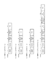
図11(a)は、本実施形態において、隣接するアクセスポイント1と隣接する無線端末3がRTS/CTS手順に従わず、データをフラグメントして通信を行い、両装置からの信号がアクセスポイント2に到達する環境でのアクセスポイント2の動作例を示すタイミングチャートである。無線端末3からアクセスポイント1に送信する、フラグメントされたDATAフレーム110、111、112を受信したアクセスポイント2は、DATAフレーム110、111、112のDurationフィールド(図7(a)〜(c)参照)に記載されている時間を省電力モードとして動作しない。その後に到達するアクセスポイント1から無線端末3に送信されたACKフレーム113、114、115のDurationフィールド(図8(c)参照)に記載されている時間から、ACK送信時間とSIFSを差分した時間を省電力モードとして動作する。当該時間内は、スリープ(Sleep)を行うため、消費電力を抑制することができる。
FIG. 11 (a) shows that in this embodiment, the
同様に、アクセスポイント1から無線端末3に送信する、フラグメントされたDATAフレーム116、117を受信したアクセスポイント2は、DATAフレーム116、117のDurationフィールド(図7(a)〜(c)参照)に記載されている時間を省電力モードとして動作しない。その後に到達する無線端末3からアクセスポイント1に送信されたACKフレーム118、119のDurationフィールド(図8(c)参照)に記載されている時間からACK送信時間とSIFSを差分した時間を省電力モードとして動作する。当該時間内は、スリープ(Sleep)を行うため、消費電力を抑制することができる。
Similarly, the
図11(b)は、本実施形態において、隣接するアクセスポイント1と隣接する無線端末3とがRTS/CTS手順に従わず、データをフラグメントして通信を行い、アクセスポイント1からの信号のみがアクセスポイント2に到達する環境でのアクセスポイント2の動作例を示すタイミングチャートである。無線端末3からアクセスポイント1に送信する、フラグメントされたDATAフレーム120、121、122は、アクセスポイント2に到達しない。その後に到達するアクセスポイント1から無線端末3に送信されたACKフレーム123、124、125のDurationフィールド(図8(c)参照)に記載されている時間から、ACK送信時間とSIFSを差分した時間を省電力モードとして動作する。当該時間内は、スリープ(Sleep)を行うため、消費電力を抑制することができる。
FIG. 11B shows that in this embodiment, the
一方、アクセスポイント1から無線端末3に送信する、フラグメントされたDATAフレーム126、127を受信したアクセスポイント2は、無線端末3からの信号を受信できないため、DATAフレーム126、127のDurationフィールド(図7(a)〜(c)参照)に記載されている時間を省電力モードとして動作する。当該時間内は、スリープ(Sleep)を行うため、消費電力を抑制することができる。
On the other hand, since the
上述した実施形態によれば、受信したフレームのMACヘッダに記載されている情報を用いることによって、受信したアクセスポイントに対して設定された送信禁止期間における省電力モードへの移行判断を行うことで、送信禁止期間にも関わらずアクティブモードで動作することによる不要な電力消費を削減することができる。 According to the above-described embodiment, by using the information described in the MAC header of the received frame, it is determined to shift to the power saving mode in the transmission prohibition period set for the received access point. Therefore, unnecessary power consumption due to the operation in the active mode can be reduced regardless of the transmission prohibition period.
なお、図1におけるアクセスポイント1、2の機能を実現するためのプログラムをコンピュータ読み取り可能な記録媒体に記録して、この記録媒体に記録されたプログラムをコンピュータシステムに読み込ませ、実行することによりスリープモードへの移行する制御処理を行ってもよい。なお、ここでいう「コンピュータシステム」とは、OSや周辺機器等のハードウェアを含むものとする。また、「コンピュータ読み取り可能な記録媒体」とは、フレキシブルディスク、光磁気ディスク、ROM、CD−ROM等の可搬媒体、コンピュータシステムに内蔵されるハードディスク等の記憶装置のことをいう。さらに「コンピュータ読み取り可能な記録媒体」とは、インターネット等のネットワークや電話回線等の通信回線を介してプログラムが送信された場合のサーバやクライアントとなるコンピュータシステム内部の揮発性メモリ(RAM)のように、一定時間プログラムを保持しているものも含むものとする。
The program for realizing the functions of the
また、上記プログラムは、このプログラムを記憶装置等に格納したコンピュータシステムから、伝送媒体を介して、あるいは、伝送媒体中の伝送波により他のコンピュータシステムに伝送されてもよい。ここで、プログラムを伝送する「伝送媒体」は、インターネット等のネットワーク(通信網)や電話回線等の通信回線(通信線)のように情報を伝送する機能を有する媒体のことをいう。また、上記プログラムは、前述した機能の一部を実現するためのものであってもよい。さらに、前述した機能をコンピュータシステムにすでに記録されているプログラムとの組み合わせで実現できるもの、いわゆる差分ファイル(差分プログラム)であってもよい。 The program may be transmitted from a computer system storing the program in a storage device or the like to another computer system via a transmission medium or by a transmission wave in the transmission medium. Here, the “transmission medium” for transmitting the program refers to a medium having a function of transmitting information, such as a network (communication network) such as the Internet or a communication line (communication line) such as a telephone line. The program may be for realizing a part of the functions described above. Furthermore, what can implement | achieve the function mentioned above in combination with the program already recorded on the computer system, what is called a difference file (difference program) may be sufficient.
以上、図面を参照して本発明の実施の形態を説明してきたが、上記実施の形態は本発明の例示に過ぎず、本発明が上記実施の形態に限定されるものではないことは明らかである。したがって、本発明の技術思想及び範囲を逸脱しない範囲で構成要素の追加、省略、置換、その他の変更を行っても良い。 As mentioned above, although embodiment of this invention has been described with reference to drawings, the said embodiment is only the illustration of this invention, and it is clear that this invention is not limited to the said embodiment. is there. Accordingly, additions, omissions, substitutions, and other changes of the components may be made without departing from the technical idea and scope of the present invention.
従来、複数の無線LANアクセスポイント(AP)が互いの送信する信号を受信することができる環境にあって、同一の周波数で異なるBSSで運用している場合において、一方のアクセスポイントが通信中は、他方のアクセスポイントは通信できないにも関わらず、受信を行い、無駄に電力が消費される。 Conventionally, in an environment where a plurality of wireless LAN access points (APs) can receive signals transmitted from each other, when operating with different BSSs at the same frequency, one access point is communicating. Even though the other access point cannot communicate, it receives and wastes power.
本発明は、アクセスポイントがモード移行(アクティブモード→省電力モード、省電力モード→アクティブモード)に要する時間を予め保持しておき、他の装置から受信した信号に記載の通信占有時間を識別し、上記通信占有時間と上記モード移行に要する時間とに基づいて移行が可能か否かを判定し、可能と判定した場合には、上記通信占有時間の間は省電力モードに移行することを特徴としている。これにより、他のアクセスポイントが使用していて通信できない間の無駄な電力消費を抑えることができる。 The present invention stores in advance the time required for the access point to change modes (active mode → power saving mode, power saving mode → active mode), and identifies the communication occupation time described in signals received from other devices. Determining whether or not the transition is possible based on the communication occupancy time and the time required for the mode transition, and transitioning to the power saving mode during the communication occupancy time if it is determined to be possible. It is said. As a result, it is possible to suppress wasteful power consumption while other access points are using and cannot communicate.
本発明は、無線LANの複数のアクセスポイント装置により構成される無線通信システムにおいて、省電力モードを用いることによって、省電力化を図ることが不可欠な用途に適用できる。 INDUSTRIAL APPLICABILITY The present invention can be applied to a use in which it is indispensable to save power by using a power saving mode in a wireless communication system constituted by a plurality of access points of a wireless LAN.
1、2 アクセスポイント
3、4 無線端末
11 アンテナ
12 無線通信処理部
13 外部ネットワーク通信処理部
14 省電力モード制御部
15 モード切替制御部
16 モード切替時間保管部
DESCRIPTION OF
Claims (2)
前記アクティブモードによる動作中に他の装置から受信した信号に含まれている通信占有時間を識別する識別部と、
前記通信占有時間において前記省電力モードへ移行して動作することが可能か否かを判定する判定部と、
前記判定部によって前記省電力モードへ移行して動作することが可能と判定された場合に、前記通信占有時間に亘って前記省電力モードへ切り替え、前記通信占有時間経過後に前記アクティブモードへ切り替えるモード切替部と
を備え、
前記判定部は、
前記アクティブモードから前記省電力モードへの切替に要する停止時間と前記省電力モードから前記アクティブモードへの切替に要する再起動時間との和と、前記通信占有時間とを比較し、前記和が前記通信占有時間より小さい場合には、前記省電力モードへ移行して動作することが可能と判定し、そうでない場合には、前記省電力モードへ移行して動作することが不可能と判定する
ことを特徴とする無線通信装置。 A wireless communication device capable of switching between an active mode for communicating with other devices and a power saving mode for reducing power consumption without communicating with other devices,
An identification unit for identifying a communication occupation time included in a signal received from another device during the operation in the active mode;
A determination unit that determines whether or not it is possible to move to the power saving mode and operate in the communication occupation time;
When said by the determination unit is determined that it is possible to operate the process proceeds to the power saving mode, switching to the power saving mode over the communication occupancy time, switching to the active mode after the lapse the communication occupancy time mode and a switching unit,
The determination unit
The sum of the stop time required for switching from the active mode to the power saving mode and the restart time required for switching from the power saving mode to the active mode is compared with the communication occupation time, If it is less than the communication occupation time, it is determined that it is possible to operate by shifting to the power saving mode, and otherwise, it is determined that it is impossible to operate by shifting to the power saving mode. A wireless communication device.
前記アクティブモードによる動作中に他の装置から受信した信号に含まれている通信占有時間を識別する識別ステップと、
前記通信占有時間において前記省電力モードへ移行して動作することが可能か否かを判定する判定ステップと、
前記判定部によって前記省電力モードへ移行して動作することが可能と判定された場合に、前記通信占有時間に亘って前記省電力モードへ切り替え、前記通信占有時間経過後に前記アクティブモードへ切り替えるモード切替ステップと
を有し、
前記判定ステップでは、
前記アクティブモードから前記省電力モードへの切替に要する停止時間と前記省電力モードから前記アクティブモードへの切替に要する再起動時間との和と、前記通信占有時間とを比較し、前記和が前記通信占有時間より小さい場合には、前記省電力モードへ移行して動作することが可能と判定し、そうでない場合には、前記省電力モードへ移行して動作することが不可能と判定する
ことを特徴とする通信動作制御方法。 A communication operation control method performed by a wireless communication device capable of switching between an active mode for communicating with another device and a power saving mode for reducing power consumption without performing communication with the other device,
An identification step for identifying a communication occupation time included in a signal received from another device during the operation in the active mode;
A determination step of determining whether or not it is possible to move to the power saving mode during the communication occupation time; and
When said by the determination unit is determined that it is possible to operate the process proceeds to the power saving mode, switching to the power saving mode over the communication occupancy time, switching to the active mode after the lapse the communication occupancy time mode possess a switching step,
In the determination step,
The sum of the stop time required for switching from the active mode to the power saving mode and the restart time required for switching from the power saving mode to the active mode is compared with the communication occupation time, If it is less than the communication occupation time, it is determined that it is possible to operate by shifting to the power saving mode, and otherwise, it is determined that it is impossible to operate by shifting to the power saving mode. A communication operation control method characterized by the above.
Priority Applications (1)
| Application Number | Priority Date | Filing Date | Title |
|---|---|---|---|
| JP2012107866A JP5856538B2 (en) | 2012-05-09 | 2012-05-09 | Wireless communication apparatus and communication operation control method |
Applications Claiming Priority (1)
| Application Number | Priority Date | Filing Date | Title |
|---|---|---|---|
| JP2012107866A JP5856538B2 (en) | 2012-05-09 | 2012-05-09 | Wireless communication apparatus and communication operation control method |
Publications (2)
| Publication Number | Publication Date |
|---|---|
| JP2013236273A JP2013236273A (en) | 2013-11-21 |
| JP5856538B2 true JP5856538B2 (en) | 2016-02-09 |
Family
ID=49762025
Family Applications (1)
| Application Number | Title | Priority Date | Filing Date |
|---|---|---|---|
| JP2012107866A Active JP5856538B2 (en) | 2012-05-09 | 2012-05-09 | Wireless communication apparatus and communication operation control method |
Country Status (1)
| Country | Link |
|---|---|
| JP (1) | JP5856538B2 (en) |
Family Cites Families (5)
| Publication number | Priority date | Publication date | Assignee | Title |
|---|---|---|---|---|
| US20020132603A1 (en) * | 2000-12-08 | 2002-09-19 | Jan Lindskog | Method for power save |
| JP3826893B2 (en) * | 2003-03-26 | 2006-09-27 | ソニー株式会社 | Wireless communication system |
| US20080123575A1 (en) * | 2006-11-27 | 2008-05-29 | Nokia Corporation | Adaptive trigger frame generation in wireless networks |
| US8542620B2 (en) * | 2009-05-05 | 2013-09-24 | Qualcomm Incorporated | Dynamic energy saving mechanism for access points |
| EP2498552A4 (en) * | 2009-11-02 | 2014-06-25 | Nec Corp | Communication device, communication system, communication device control method, and communication device control program |
-
2012
- 2012-05-09 JP JP2012107866A patent/JP5856538B2/en active Active
Also Published As
| Publication number | Publication date |
|---|---|
| JP2013236273A (en) | 2013-11-21 |
Similar Documents
| Publication | Publication Date | Title |
|---|---|---|
| EP3024289B1 (en) | Communication system, communication apparatus and communication method, and computer program | |
| US9030985B2 (en) | Handling mismatch of cryptographic keys and related battery drain and communication exchange failures | |
| JP5020322B2 (en) | Synchronization between wireless devices while saving power | |
| EP2803223B1 (en) | Systems and methods to transmit configuration change messages between an access point and a station | |
| JP4674155B2 (en) | Wireless communication terminal and load distribution method for relay device thereof | |
| EP2658308A1 (en) | Communication device, communication method, terminal device and communication system | |
| JP5715637B2 (en) | Wireless communication apparatus, wireless communication method, and processing circuit | |
| JP2006319444A (en) | Wireless lan system, relaying terminal equipment, and relaying method | |
| JP4889290B2 (en) | Wireless communication terminal and wireless communication method | |
| JP5390300B2 (en) | Wireless device and method for switching operation mode of wireless device | |
| WO2016178338A1 (en) | Information processing apparatus, information processing method and program | |
| JP5675669B2 (en) | Access point device and wireless communication method | |
| JPWO2009008056A1 (en) | Mobile station apparatus and cell selection method | |
| CN113133092B (en) | Energy-saving control method and related equipment | |
| CN114375045A (en) | Resource pool switching method and device, terminal and network side equipment | |
| JP5749682B2 (en) | Access point device and communication operation control method | |
| JP5856538B2 (en) | Wireless communication apparatus and communication operation control method | |
| JP5997661B2 (en) | Repeater device and repeater sleep control method | |
| EP4195756A1 (en) | Measurement method, measurement apparatus, terminal and network device | |
| CN109788535B (en) | Power saving method and device for Internet of things equipment | |
| JP5896475B2 (en) | Wireless access point, communication system, wireless terminal, and communication program | |
| JP2007124127A (en) | Wireless lan terminal and wireless lan system | |
| JP5028653B2 (en) | Radio communication system and mobile radio terminal apparatus | |
| JP5497694B2 (en) | access point | |
| WO2022085140A1 (en) | Communication device and communication method |
Legal Events
| Date | Code | Title | Description |
|---|---|---|---|
| A621 | Written request for application examination |
Free format text: JAPANESE INTERMEDIATE CODE: A621 Effective date: 20140731 |
|
| A977 | Report on retrieval |
Free format text: JAPANESE INTERMEDIATE CODE: A971007 Effective date: 20150408 |
|
| A131 | Notification of reasons for refusal |
Free format text: JAPANESE INTERMEDIATE CODE: A131 Effective date: 20150414 |
|
| A521 | Written amendment |
Free format text: JAPANESE INTERMEDIATE CODE: A523 Effective date: 20150610 |
|
| TRDD | Decision of grant or rejection written | ||
| A01 | Written decision to grant a patent or to grant a registration (utility model) |
Free format text: JAPANESE INTERMEDIATE CODE: A01 Effective date: 20151208 |
|
| A61 | First payment of annual fees (during grant procedure) |
Free format text: JAPANESE INTERMEDIATE CODE: A61 Effective date: 20151211 |
|
| R150 | Certificate of patent or registration of utility model |
Ref document number: 5856538 Country of ref document: JP Free format text: JAPANESE INTERMEDIATE CODE: R150 |