JP4533085B2 - Wireless communication apparatus, communication system, wireless communication method, and computer program - Google Patents
Wireless communication apparatus, communication system, wireless communication method, and computer program Download PDFInfo
- Publication number
- JP4533085B2 JP4533085B2 JP2004312920A JP2004312920A JP4533085B2 JP 4533085 B2 JP4533085 B2 JP 4533085B2 JP 2004312920 A JP2004312920 A JP 2004312920A JP 2004312920 A JP2004312920 A JP 2004312920A JP 4533085 B2 JP4533085 B2 JP 4533085B2
- Authority
- JP
- Japan
- Prior art keywords
- mode
- communication
- time
- wireless communication
- wireless
- Prior art date
- Legal status (The legal status is an assumption and is not a legal conclusion. Google has not performed a legal analysis and makes no representation as to the accuracy of the status listed.)
- Expired - Fee Related
Links
Images


Classifications
-
- H—ELECTRICITY
- H04—ELECTRIC COMMUNICATION TECHNIQUE
- H04W—WIRELESS COMMUNICATION NETWORKS
- H04W92/00—Interfaces specially adapted for wireless communication networks
-
- H—ELECTRICITY
- H04—ELECTRIC COMMUNICATION TECHNIQUE
- H04W—WIRELESS COMMUNICATION NETWORKS
- H04W80/00—Wireless network protocols or protocol adaptations to wireless operation
-
- H—ELECTRICITY
- H04—ELECTRIC COMMUNICATION TECHNIQUE
- H04W—WIRELESS COMMUNICATION NETWORKS
- H04W92/00—Interfaces specially adapted for wireless communication networks
- H04W92/04—Interfaces between hierarchically different network devices
- H04W92/10—Interfaces between hierarchically different network devices between terminal device and access point, i.e. wireless air interface
-
- H—ELECTRICITY
- H04—ELECTRIC COMMUNICATION TECHNIQUE
- H04W—WIRELESS COMMUNICATION NETWORKS
- H04W92/00—Interfaces specially adapted for wireless communication networks
- H04W92/16—Interfaces between hierarchically similar devices
- H04W92/18—Interfaces between hierarchically similar devices between terminal devices
Description
本発明は、無線通信装置、通信システム、無線通信方法、及びコンピュータプログラムに関し、特に、無線通信装置間で無線通信を行うために用いて好適なものである。 The present invention relates to a wireless communication device, a communication system, a wireless communication method, and a computer program, and is particularly suitable for use in performing wireless communication between wireless communication devices.
近年、無線端末装置が通信を行う際に利用される無線LAN(Local Area Network)には、非特許文献1(IEEE802.11(1999edition))に記載されているように、有線ネットワークに接続しているアクセスポイント(集中調停制御装置)が存在している。そして、無線LANでは、アクセスポイントが無線ネットワーク内にある複数の無線端末装置のアクセスタイミングを調停するインフラストラクチャモード(以下インフラモードと略称する)と、無線端末装置間でアクセスタイミングを決定するアドホックモードとが存在する。 In recent years, as described in Non-Patent Document 1 (IEEE802.11 (1999 edition)), a wireless LAN (Local Area Network) used when a wireless terminal device performs communication is connected to a wired network. Access point (central arbitration control device) exists. In a wireless LAN, an infrastructure mode (hereinafter abbreviated as infrastructure mode) in which an access point arbitrates access timings of a plurality of wireless terminal devices in a wireless network, and an ad hoc mode in which access timings are determined between wireless terminal devices. And exist.
アクセスポイントを経由するインフラモードでは、アクセスポイントを経由するため、アドホックモードと比較して、スループットが低下するという短所を持つが、有線LANやインターネットへのアクセスが実現できる。一方、アドホックモードでは、無線端末装置同士で直接通信するため、スループットは上がるが、有線LANやインターネットへのアクセスが出来ないという短所を持つ。そこで、両者の長所を生かすためにインフラモードとアドホックモードとの切り替えによる通信方式が提案されていた(特許文献1を参照)。 In the infrastructure mode that passes through the access point, since it passes through the access point, there is a disadvantage that the throughput is lower than in the ad hoc mode, but access to a wired LAN or the Internet can be realized. On the other hand, in the ad hoc mode, since wireless terminals directly communicate with each other, the throughput increases, but there is a disadvantage that access to a wired LAN or the Internet is not possible. Therefore, in order to take advantage of both advantages, a communication method by switching between the infrastructure mode and the ad hoc mode has been proposed (see Patent Document 1).
また、リアルタイムでのデータ通信を非特許文献1の無線LANで実現するために、現在、非特許文献2(IEEE802.11e/D8.0(Feb、2004))の方式が検討されている。その中でもインフラモードとアドホックモードそれぞれの長所を生かすために、インフラモード下であっても無線端末装置間で直接通信を行えるモード(以下DLP(Direct Link Protocol)モードと略称する)が提案されている。
Further, in order to realize real-time data communication with the wireless LAN of
しかしながら、以上のようにしてインフラモードからアドホックに切り替えて通信をする場合でも、DLPを用いて通信する場合でも、アクセスポイント経由では通信できていても、無線端末装置の配置されている場所の条件によっては、直接通信するためには無線端末装置間で電波が届かない場合も考えられる。 However, even when communication is performed by switching from infrastructure mode to ad hoc as described above, even when communication is performed using DLP, communication is possible via an access point, the conditions of the location where the wireless terminal device is located In some cases, radio waves do not reach between wireless terminal devices for direct communication.
そこで、直接通信が可能か否かを確認する方法として、アクセスポイント経由で直接通信を行うための要求を相手に通知し、その応答信号が受信できるか否かを確認できるか否かで直接通信が可能か否かを判断する方法や(特許文献2を参照)、他の無線端末装置が出す電波をあらかじめ全て受信し、受信できた無線端末装置のリストを作成することで直接通信が可能な無線端末装置か否かを判断する方法が提案されている(特許文献3を参照)。 Therefore, as a method of confirming whether or not direct communication is possible, direct communication is performed depending on whether or not the request for direct communication via the access point is notified to the other party and whether or not the response signal can be received. (See Patent Document 2), or by receiving all the radio waves emitted by other wireless terminal devices in advance and creating a list of received wireless terminal devices, direct communication is possible A method for determining whether or not the terminal is a wireless terminal device has been proposed (see Patent Document 3).
しかしながら、前述した従来技術では、電波が届くか否か、すなわち通信できるか否かについては判断できるが、実際には電波が届く場合でも電波が伝搬する際の環境があまり良くないために、無線リンク速度を下げなければならない場合も考えられる。この場合、アクセスポイント経由に比べてスループットが却って低下することも考えられる。また、特許文献2の場合も特許文献3の場合も、無線パケットの種別や送信元の無線端末装置のアドレスを取得するために、ある期間、受信可能な全ての無線パケットを受信し、アドレス取得やパケット種別の判定を行う必要があった。このため、これらの処理が非常に大きな負荷となっていた。また、負荷が重いために情報の取りこぼしが生じる可能性もあった。 However, in the above-described conventional technology, it is possible to determine whether or not radio waves reach, that is, whether or not communication is possible. However, even if radio waves actually arrive, the environment in which radio waves propagate is not so good. There may be cases where the link speed has to be reduced. In this case, it is conceivable that the throughput decreases rather than via the access point. In both cases of Patent Document 2 and Patent Document 3, in order to acquire the type of wireless packet and the address of the wireless terminal device that is the transmission source, all wireless packets that can be received for a certain period are received and the address is acquired. It was necessary to determine the packet type. For this reason, these processes have become very heavy loads. In addition, there is a possibility that information may be lost due to heavy load.
さらに、これら従来技術では、直接通信することが可能な無線端末装置の存在の有無は分かるが、アクセスポイント経由の場合と比較して直接通信の場合にスループットの向上が得られるかどうかまでは実際に通信しないことには判断できなかった。 Furthermore, in these conventional techniques, it is possible to know whether or not there is a wireless terminal device capable of direct communication, but it is actually the case whether or not throughput improvement can be obtained in the case of direct communication compared to the case of via an access point. I couldn't judge that I didn't communicate.
本発明は、前述の問題点に鑑みてなされたものであり、通信状況や通信環境に応じて、2つの無線通信装置が直接通信をするか、アクセスポイント経由で通信するかを選択できるようにすることを目的とする。 The present invention has been made in view of the above-described problems, and can select whether the two wireless communication apparatuses communicate directly or via an access point depending on the communication status and communication environment. The purpose is to do.
本発明の無線端末装置は、アクセスポイント経由で相手装置と無線通信を行う第1のモードと、前記アクセスポイントを経由せずに前記相手装置と無線通信を直接行う第2のモードとのうち、何れかのモードで通信を行う無線通信装置であって、前記第1のモードにおいて通信した信号に基づいて、前記無線通信装置と前記アクセスポイントとの間の通信速度を判定する第1の判定手段と、前記第2のモードにおいて通信した信号に基づいて、前記無線通信装置と前記相手装置との間の通信速度を判定する第2の判定手段と、前記第1の判定手段により判定された通信速度と送信されるデータのサイズとに基づいて、前記第1のモードで通信するときに前記相手装置へ前記データが到達するまでに少なくとも必要な第1の時間を取得すると共に、前記第2の判定手段により判定された通信速度と前記データのサイズとに基づいて、前記第2のモードで通信するときに前記相手装置へ前記データが到達するまでに少なくとも必要な第2の時間を取得する取得手段と、前記取得手段により取得した前記第1の時間と前記第2の時間との比較結果に基づいて、前記相手装置と通信するモードを選択する選択手段と、を有し、前記第1の時間は、前記無線通信装置から送信されたデータが前記アクセスポイントに到達するまでの所要時間と、前記アクセスポイントから送信されたデータが前記相手装置に到達するまでの所要時間と、前記無線通信装置と前記アクセスポイントとのそれぞれがデータ送信開始までに少なくとも待機が必要な待機時間と、に基づいて算出される時間であり、前記第2の時間は、前記無線通信装置から送信されたデータが前記相手装置へ直接到達するまでの所要時間と、前記無線通信装置がデータ送信開始までに少なくとも待機が必要な待機時間と、に基づいて算出される時間であり、前記所要時間のそれぞれは、通信速度と、送信されるデータのサイズとに応じて変化する時間であり、前記待機時間のそれぞれは、固定の時間であることを特徴とする。 The wireless terminal device of the present invention includes a first mode in which wireless communication is performed with a counterpart device via an access point , and a second mode in which wireless communication is performed directly with the counterpart device without passing through the access point. a wireless communication apparatus for communicating in either mode, based on a signal communicated Oite in the first mode, the first determining the communication speed between the access point and the wireless communication device and determining means, on the basis of the second mode to your have communicating signal, a second determination means for determining the communication speed between the wireless communication device and the counterpart device, by the first judging means Based on the determined communication speed and the size of data to be transmitted, it is possible to acquire at least a first time required for the data to reach the counterpart device when communicating in the first mode. Based on the communication speed determined by the second determination means and the size of the data, the second necessary at least until the data reaches the counterpart device when communicating in the second mode. comprising obtaining means for obtaining a time, based on a result of comparison between the obtained and the first time the second time by the acquisition unit, and a selecting means for selecting a mode for communicating with the partner apparatus, the The first time includes a time required for data transmitted from the wireless communication device to reach the access point, a time required for data transmitted from the access point to reach the counterpart device, and Each of the wireless communication device and the access point is a time calculated based on at least a standby time that needs to be waited until data transmission starts, The time of 2 is based on the time required for the data transmitted from the wireless communication device to reach the counterpart device directly and the standby time that the wireless communication device needs to wait at least before starting data transmission. Each of the required times is a time that varies according to a communication speed and a size of data to be transmitted, and each of the waiting times is a fixed time. To do.
本発明の通信システムは、前記記載の複数の無線端末装置と、前記アクセスポイントを有することを特徴とする。 A communication system according to the present invention includes the plurality of wireless terminal devices described above and the access point.
本発明の無線通信方法は、アクセスポイント経由で相手装置と無線通信装置が無線通信を行う第1のモードと、前記アクセスポイントを経由せずに前記相手装置と無線通信装置が無線通信を直接行う第2のモードとのうち、何れかのモードで通信を行う無線通信方法であって、前記第1のモードにおいて通信した信号に基づいて、前記無線通信装置と前記アクセスポイントとの間の通信速度を判定する第1の判定工程と、前記第2のモードにおいて通信した信号に基づいて、前記無線通信装置と前記相手装置との間の通信速度を判定する第2の判定工程と、前記第1の判定手段により判定された通信速度と送信されるデータのサイズとに基づいて、前記第1のモードで通信するときに前記相手装置へ前記データが到達するまでに少なくとも必要な第1の時間を取得すると共に、前記第2の判定工程において判定された通信速度と前記データのサイズとに基づいて、前記第2のモードで通信するときに前記相手装置へ前記データが到達するまでに少なくとも必要な第2の時間を取得する取得工程と、前記取得工程により取得した前記第1の時間と前記第2の時間との比較結果に基づいて、前記相手装置と通信するモードを選択する選択工程と、を有し、前記第1の時間は、前記無線通信装置から送信されたデータが前記アクセスポイントに到達するまでの所要時間と、前記アクセスポイントから送信されたデータが前記相手装置に到達するまでの所要時間と、前記無線通信装置と前記アクセスポイントとのそれぞれがデータ送信開始までに少なくとも待機が必要な待機時間と、に基づいて算出される時間であり、前記第2の時間は、前記無線通信装置から送信されたデータが前記相手装置へ直接到達するまでの所要時間と、前記無線通信装置がデータ送信開始までに少なくとも待機が必要な待機時間と、に基づいて算出される時間であり、前記所要時間のそれぞれは、通信速度と送信されるデータのサイズとに応じて変化する時間であり、前記待機時間のそれぞれは、固定の時間であることを特徴とする。 Wireless communication method of the present invention performs a first mode in which the remote device via the wireless communication apparatus performs wireless communication through the access point, the destination device and the wireless communication device is a wireless communication not via the access point directly of the second mode, a wireless communication method for performing communication in either mode, based on a signal communicated Oite in the first mode, between the access point and the wireless communication device a first determination step of determining the communication speed, on the basis of the second contact have to communicate signals to mode, a second determination step of determining the communication speed between the wireless communication device and the counterpart device the first on the basis of the size of the data to be transmitted with the determined communication speed by the determination means, at least必until the data to the destination device is reached when communicating with the first mode The first time is acquired, and the data arrives at the counterpart device when communicating in the second mode based on the communication speed determined in the second determination step and the size of the data. A mode for communicating with the counterpart device based on a comparison result between the acquisition step for acquiring at least the second time necessary until the acquisition and the first time acquired by the acquisition step and the second time. a selection step of selecting, the, the first time, the wireless data transmitted from the communication device and the time required to reach the access point, the partner data transmitted from the access point Based on the time required to reach the device and the waiting time that each of the wireless communication device and the access point needs to wait at least before starting data transmission. The second time is at least a waiting time until the data transmitted from the wireless communication device reaches the counterpart device directly and before the wireless communication device starts data transmission. Is a time calculated based on the required waiting time, each of the required times is a time that varies depending on the communication speed and the size of the data to be transmitted, and each of the waiting times is It is characterized by a fixed time .
本発明のコンピュータプログラムは、前記無線通信方法の各工程をコンピュータに実行させることを特徴とする。 A computer program according to the present invention causes a computer to execute each step of the wireless communication method .
本発明によれば、通信速度と、送信されるデータのサイズとに応じて変化する時間(すなわち、第1のモードで通信する場合において無線通信装置から送信されたデータがアクセスポイントに到達するまでの所要時間、及びアクセスポイントから送信されたデータが相手装置に到達するまでの所要時間、並びに、第2のモードで通信する場合において無線通信装置から送信されたデータが相手装置へ直接到達するまでの所要時間)と、通信速度と、送信されるデータのサイズとによっては変化しない時間(すなわち、第1のモードで通信する場合において無線通信装置とアクセスポイントとのそれぞれがデータ送信開始までに少なくとも待機が必要な待機時間、並びに、第2のモードで通信する場合において、無線通信装置がデータ送信開始までに少なくとも待機が必要な待機時間)と、を考慮した上で第1のモード、第2のモードのどちらがより通信に時間がかかるかを比較し、使用するモードを選択するので、実際の通信状況や通信環境に適したモードを選択することができる。 According to the present invention, a time that varies depending on the communication speed and the size of data to be transmitted (that is, until data transmitted from the wireless communication device reaches the access point in the case of communication in the first mode). Required time until the data transmitted from the access point arrives at the partner device, and until the data transmitted from the wireless communication device directly reaches the partner device when communicating in the second mode. Required time), the communication speed, and the time that does not change depending on the size of data to be transmitted (that is, when communicating in the first mode, each of the wireless communication device and the access point must at least start data transmission). The wireless communication device starts data transmission when communicating in the standby mode that requires standby and in the second mode. In this case, the first mode and the second mode take longer to communicate, and the mode to be used is selected. A mode suitable for the situation and the communication environment can be selected.
(第1の実施形態)
次に、図面を参照しながら、本発明の第1の実施形態について説明する。なお、以下では、IEEE802.11e/D8.0で規定されているDLPモードでパーソナルコンピュータ等の無線端末装置同士が通信を直接行う場合を例に挙げて説明する。
図1は、本実施形態における無線通信システムの概略構成の一例を示す図である。同図において、101はアクセスポイント、102は第一の無線端末装置、103は第二の無線端末装置、104はアクセスポイント101の通信範囲を示す。
(First embodiment)
Next, a first embodiment of the present invention will be described with reference to the drawings. In the following, a case where wireless terminal devices such as personal computers directly communicate with each other in the DLP mode defined by IEEE802.11e / D8.0 will be described as an example.
FIG. 1 is a diagram illustrating an example of a schematic configuration of a wireless communication system according to the present embodiment. In the figure, 101 is an access point, 102 is a first wireless terminal device, 103 is a second wireless terminal device, and 104 is a communication range of the
アクセスポイント101と、アクセスポイント101の通信範囲104内に存在する第一の無線端末装置102及び第二の無線端末装置103が無線で接続されている。アクセスポイント101は、場合によっては有線LAN105に接続し、通信範囲104内に存在する無線端末装置102、103との間で、有線LAN105を経由した通信を実現する。
The
アクセスポイント101は、IEEE802.11e/D8.0に記載されているQoS(Quality of Service)、特に2つの無線端末装置101、102間の直接通信を通信範囲104に提供する機能を有する。
第一の無線端末装置102及び第二の無線端末装置103は、DLPモードの通信に移行するのかをユーザーがいつ指示してもいいように、アクセスポイント101とのデータ通信時の無線リンク速度を常時記録し、平均値を求めておく。
The
The first
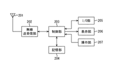
図2は、第一及び第二の無線端末装置102、103の概略構成の一例を示すブロック図である。
図2において、第一及び第二の無線端末装置102、103は、アンテナ201と、無線送受信部202と、制御部203と、記憶部204と、I/O部205と、表示部206と、操作部207とを備えている。
無線送受信部202は、制御部203で生成された情報に対して、例えば変調処理を行いアンテナ201に出力する。また、無線送受信部202は、アンテナ201で受信された情報に対して、例えば復調処理を行い制御部203に出力する。
制御部203は、記憶部204に記憶されている制御プログラムを実行するなどして、装置を統括制御し、各種の処理を行う。
FIG. 2 is a block diagram illustrating an example of a schematic configuration of the first and second
In FIG. 2, the first and second
The wireless transmission /
The
記憶部204は、制御部203により実行される制御プログラムや、各種のデータが記憶されている。また、後述するようにして、制御部203が、DLPモードによる通信の有効性をどのように判断する際に使用されるテーブル401なども記憶部204に記憶されている。さらに、記憶部204は、制御部203が制御プログラムを実行する際のワークエリアとしても機能する。
The
I/O部205は、外部の装置(プリンタなど)を接続し、音声や映像などに関するデータのやり取りを外部の装置と行うためのものである。
表示部206は、制御部203で行われる処理の内容に応じた各種の表示を行う。例えば、後述するようにして他の無線端末装置との間で行われる通信状況などを表示する。
操作部207は、第一及び第二の無線端末装置102、103を操作するための各種キーを備えている。この各種キーの操作内容は、制御部203に出力され、制御部203は、この操作内容に基づいて各種の処理を行う。
The I /
The
The
以下に、以上のようにして構成される第一及び第二の無線端末装置102、103と、アクセスポイント101の処理動作の一例について説明する。なお、以下では、第一及び第二の無線端末装置102、103が通信を行う際の処理動作について説明するが、これ以外の処理動作を、第一及び第二の無線端末装置102、103と、アクセスポイント101が行うことが可能であるということは言うまでもない。
Hereinafter, an example of processing operations of the first and second
図1において、第一の無線端末装置102から第二の無線端末装置103へ、アクセスポイント101を経由してデータ通信を行う場合、送りたいデータのヘッダ部に、宛先として第二の無線端末装置103のIPアドレスをつけ、送り元として第一の無線端末装置102のIPアドレスをつける。次に、IPアドレスをつけたデータの先頭に、宛先MACアドレス(Media Access Control Address)としてアクセスポイント101のMACアドレスをつけ、送り元MACアドレスとして第一の無線端末装置102のMACアドレスをつける。そして、MACアドレスを付けたデータをアクセスポイント101宛に送信する。
In FIG. 1, when data communication is performed from the first
これらのデータを受けたアクセスポイント101は、宛先MACアドレスと送り元MACアドレスとをデータから外す。そして、宛先としてつけられているIPアドレスを確認する。この確認の結果、宛先が第二の無線端末装置103であることが分かると、そのIPアドレスの前に、宛先MACアドレスとして第二の無線端末装置103のMACアドレスをつけ、送り元MACアドレスとしてアクセスポイント101のMACアドレスをつける。
Receiving these data, the
その後、アクセスポイント101は、これらのMACアドレスをつけたデータを第二の無線端末装置103宛に送信する。このデータを受信した第二の無線端末装置103は、宛先MACアドレスと送り元MACアドレスとをデータから外す。そして、データのヘッダに宛先としてつけられているIPアドレスが自分(第二の無線端末装置103)であることを確認するとともに、送り元が第一の無線端末装置102であることを知る。
なお、第二の無線端末装置103から第一の無線端末装置102宛にデータを送信する場合にも同様の処理が行われる。
Thereafter, the
The same processing is performed when data is transmitted from the second
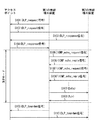
IEEE802.11e/D8.0に記載されているように、アクセスポイント101に接続している第一の無線端末装置102が第二の無線端末装置103とDLPモードによる通信を行う場合には、図3に示す動作シーケンスが実行される。
まず、第一の無線端末装置102は、第二の無線端末装置103とDLPモードによる通信を行いたい旨のDLP_request信号を、アクセスポイント101を介して第二の無線端末装置103に通知する(ステップS101、S102)。このDLP_request信号には、第一の無線端末装置102のMACアドレスやアプリケーションの種別といったDLPモードによる通信を行うのに必要な情報が含まれている。
As described in IEEE802.11e / D8.0, when the first
First, the first
DLP_request信号を受信した第二の無線端末装置103は、DLPモードによる通信を行いたい旨の要求を受け取ったことを示すDLP_response信号を、アクセスポイント101を介して第一の無線端末装置102に通知する。このDLP_response信号には、第二の無線端末装置103のMACアドレスや、DLPモードによる通信を了解した旨を知らせる情報など、DLPモードによる通信を行うのに必要な情報が含まれている。DLP_response信号を、アクセスポイント101を介して第一の無線端末装置102に送信した後(ステップS103)、第二の無線端末装置103は、DLPモードによる通信に移行する。一方、第一の無線端末装置102は、DLP_response信号を受信した後(ステップS104)、DLPモードによる通信に移行する。
Receiving the DLP_request signal, the second
DLPモードによる通信に移行した後、DLP_request信号を送信した第一の無線端末装置102は、第二の無線端末装置103と直接通信が可能か否かを確認するために、ICMP_echo_request信号を第二の無線端末装置103宛に送信する(ステップS105)。このICMP_echo_request信号では、DLP_request信号と異なり、宛先MACアドレスも宛先IPアドレスも第二の無線端末装置103のものになっている。つまり、アクセスポイント101を経由せずに、直接第二の無線端末装置103に送信する。
After shifting to communication in the DLP mode, the first
ICMP_echo_request信号を受信した第二の無線端末装置103は、ICMP_echo_reply信号を第一の無線端末装置102宛に送信する(ステップS106)。ICMP_echo_reply信号では、宛先MACアドレスも宛先IPアドレスも第一の無線端末装置103のものにし、直接第一の無線端末装置102に送信する。第一の無線端末装置102は、ICMP_echo_request信号を送信したときの無線リンク速度と、ICMP_echo_reply信号を受信したときの無線リンク速度とを記録しておく。
The second
そして、この無線リンク速度をDLPモードによる通信時の無線リンク速度とし、アクセスポイント101経由時の無線リンク速度と比較する。この比較の結果、DLPモードによる通信が有効であると判断すれば、DLPモードによる通信を実行し(ステップS107、S108)、有効でないと判断したらアクセスポイント101経由で第二の無線端末装置103にDLPモードによる通信の終了を通知する(ステップS109、S110)。
Then, this wireless link speed is set as a wireless link speed at the time of communication in the DLP mode, and is compared with the wireless link speed via the
図5に、DLPモードによる通信が有効であるか否かを判断する際の処理の一例を説明するフローチャートを示す。
ICMP_echo_request信号とICMP_echo_reply信号のやり取り(ステップS105、S106)が1回だけでは、やり取りの回数が少ないために、DLPモードによる通信が実現可能か否かの確認結果の信頼性が低く、無線リンク速度の測定においても信頼性が低い。このため、本実施形態では、ICMP_echo_request信号とICMP_echo_reply信号とのやり取りを複数回実行するようにしている。また、本実施形態では、DLP_request信号を送信した無線端末装置が、DLPモードによる通信の有効性の判断を判断するようにしている。
FIG. 5 is a flowchart for explaining an example of processing when it is determined whether communication in the DLP mode is valid.
Since there is only a small number of exchanges between the ICMP_echo_request signal and the ICMP_echo_reply signal (steps S105 and S106), the reliability of the confirmation result as to whether communication in the DLP mode is feasible is low, and the radio link speed is low. Even in measurement, the reliability is low. For this reason, in this embodiment, the exchange of the ICMP_echo_request signal and the ICMP_echo_reply signal is executed a plurality of times. In the present embodiment, the wireless terminal apparatus that has transmitted the DLP_request signal determines the validity of communication in the DLP mode.
第二の無線端末装置103から第一の無線端末装置102にDLP_response信号が送信された後に、第一及び第二の無線端末装置102、103が、DLPモードによる通信に移行すると(ステップS201)、第一の無線端末装置102は、第二の無線端末装置103宛にICMP_echo_request信号を送信する(ステップS202)。
そして、第一の無線端末装置102は、ICMP_echo_request信号に対応するICMP_echo_reply信号を、一定時間内に受信したか否かを判断する(ステップS203)。この判断の結果、ICMP_echo_reply信号を一定時間内に受信できなかった場合には(ステップS203のNo)、第二の無線端末装置103からの応答が無いと判断し、応答無し回数をカウントアップする(ステップS205)。
After the DLP_response signal is transmitted from the second
Then, the first
一方、ICMP_echo_reply信号を、一定時間内に受信できた場合には(ステップS203のYes)、第二の無線端末装置103からの応答が有ったと判断し、応答有り回数をカウントアップするとともに(ステップS204)、ICMP_echo_request信号を送信したときの無線リンク速度と、ICMP_echo_reply信号を受信したときの無線リンク速度とを記録する。このとき、既に記録されている無線リンク速度との平均値を求め、求めた無線リンク速度の平均値を記録するようにするのが好ましい。
On the other hand, if the ICMP_echo_reply signal can be received within a certain time (Yes in step S203), it is determined that there is a response from the second
そして、ICMP_echo_request信号を、予め設定されている規定回数だけ送信したか否かを確認し(ステップS206)、規定回数の送信を行うまでステップS202〜S206を繰り返し行う。そして、規定回数の送信が終了していることを確認すれば(ステップS206のYes)、DLPモードによる通信の有効性を判断することになる(ステップS207)。 Then, it is confirmed whether or not the ICMP_echo_request signal has been transmitted a predetermined number of times set in advance (step S206), and steps S202 to S206 are repeated until the predetermined number of times of transmission is performed. If it is confirmed that the specified number of transmissions have been completed (Yes in step S206), the effectiveness of communication in the DLP mode is determined (step S207).
ここで、DLPモードによる通信の有効性をどのように判断するかについて説明する。この判断のポイントは、IEEE802.11(1999edition)に記載されている、無線LANフレームフォーマット及び送信待ち時間である。一例として、仮にMPDU(Mac Protocol Data Unit)の長さが1100バイトとすると、無線リンク速度によってMPDUの時間的な長さは、図4に示すテーブル401のMPDU長の欄に示す値となる。無線LANの規格上、MPDUの無線リンク速度によらずPLCP(Physical Layer Convergence Protocol)ヘッダ部の無線リンク速度は固定であり、およそ200μsとなる。 Here, how to determine the effectiveness of communication in the DLP mode will be described. The point of this judgment is the wireless LAN frame format and transmission waiting time described in IEEE802.11 (1999 edition). As an example, if the length of an MPDU (Mac Protocol Data Unit) is 1100 bytes, the time length of the MPDU depends on the wireless link speed, and is the value shown in the MPDU length column of the table 401 shown in FIG. According to the wireless LAN standard, the wireless link speed of the PLCP (Physical Layer Convergence Protocol) header is fixed regardless of the wireless link speed of the MPDU, and is approximately 200 μs.
PLCPヘッダとMPDUの合計時間は、図4に示すテーブル401のPLCPヘッダ付の欄に示す値となる。また、無線LANの規格上、最速の待ち時間の場合、1回データを送って次にデータが送れるようになるには260μs待たなければならない。データの送信に要する時間と待ち時間の合計を図4に示すテーブル401の(301列)の欄に示す。 The total time of the PLCP header and MPDU is the value shown in the column with the PLCP header in the table 401 shown in FIG. Further, according to the wireless LAN standard, in the case of the fastest waiting time, it is necessary to wait for 260 μs in order to send data once and to be able to send data next time. The total of time required for data transmission and waiting time is shown in the column (301 column) of the table 401 shown in FIG.
また、アクセスポイント101経由でデータを送る場合、自無線端末装置(例えば第一の無線端末装置102)からアクセスポイント101までデータが届くに要する時間と、アクセスポイント101から相手の無線端末装置(例えば第二の無線端末装置103)までデータが届くのに要する時間が経過するまでは、次のデータを送れない。このため、最速でも、図4に示すテーブル401の(302列)の欄に示す時間だけ待つ必要がある。なお、図4において、(302列)の欄に示す値は、(301列)の欄に示す値のほぼ倍となる。
When data is sent via the
本実施形態の場合、(301列)の欄に示す値は、直接通信時における最速時のデータ伝送時間と同じ時間を示し、(302列)の欄に示す値は、アクセスポイント101経由時における最速時のデータ伝送時間と同じ時間を示すことになる。従って、DLPモードによる通信が有効か否かを判断するには、図4に示すテーブル401の(301列)の欄に示す値と、(302列)の欄に示す値とを用いて、DLPモード時の無線リンク速度と、アクセスポイント101経由時の無線リンク速度とを比較すればよい。
In the case of this embodiment, the value shown in the (301 column) column indicates the same time as the fastest data transmission time during direct communication, and the value shown in the (302 column) column is the value when passing through the
例えば、アクセスポイント101経由時における無線リンク速度が11Mbpsであり、DLPモード時における無線リンク速度が5.5Mbpsであるときには、若干DLP通信のほうが早い(すなわち、無線リンク速度が11Mbpsのときの(302列)の欄の値は2.52msであるのに対し、無線リンク速度が5.5Mbpsのときの(301列)の欄の値は2.06msである)。したがって、DLPモードによる通信を実行すると判断する。
For example, when the wireless link speed through the
一方、例えば、アクセスポイント101経由時における無線リンク速度が11Mbpsであり、DLPモード時における無線リンク速度が2Mbpsであるときには、DLPモードによる通信を実行するよりも、アクセスポイント101を経由して通信した方が実行するスループットが向上することが期待できる(すなわち、無線リンク速度が11Mbpsのときの(302列)の欄の値は2.52msであるのに対し、無線リンク速度が2Mbpsのときの(301列)の欄の値は4.86msである)。したがって、DLPモードによる通信を終了し、アクセスポイント101経由で通信すると判断する。
On the other hand, for example, when the wireless link speed at the time of passing through the
以上のように本実施形態では、第一の無線端末装置102は、DLPモードに移行した後に、ICMP_echo_request信号を第二の無線端末装置103に直接送信し、この返答として第二の無線端末装置103から一定時間内にICMP_echo_reply信号を受信すると、応答有り回数をカウントアップする一方、一定時間内にICMP_echo_reply信号を受信しなかった場合には、応答無し回数をカウントアップするようにしたので、第二の無線端末装置103とDLPモードで通信を直接行うことが可能であるか否かを容易に判断することができるようになる。
As described above, in the present embodiment, the first
また、第一の無線端末装置102は、アクセスポイント101と通信したときの無線リンク速度を記憶しておくとともに、第二の無線端末装置103とDLPモードで通信したときの無線リンク速度を記憶し、これら記憶した無線リンク速度の比較結果に応じて、アクセスポイント101を介して第二の無線端末装置103と通信するよりも、第二の無線端末装置103と直接通信する方が、効率よく通信できると判断した場合には、DLPモードによる通信を行い、そうでなければ、DLPモードによる通信を終了するようにした。このようにすれば、アクセスポイント101との通信速度と、DLPモードにおける第二の無線端末装置103との通信速度とを比較することができ、DLPモードで通信を行うのが有効であるか否かを容易に判断することができる。
The first
さらに、第一の無線端末装置102は、アクセスポイント101と通信したときの無線リンク速度の平均値を記憶しておくとともに、第二の無線端末装置103とDLPモードで通信したときの無線リンク速度の平均値を記憶するようにしたので、無線リンク速度の信頼性をより向上させることができ、DLPモードで通信を行うのが有効であるか否かをより正確に判断することができる。
Further, the first
なお、本実施形態では、DLPモードによる通信の相手を捜索し、その際の無線リンク速度を確認する方法としてICMP_echo_request信号と、ICMP_echo_reply信号とを用いたが、無線リンク速度を確認する方法はこれに限定されない。例えば、別途独自のDLP端末応答要求信号と、その応答信号であるDLP端末応答信号とを組み合わせて使用しても、本実施形態の無線通信システムと同じ動作になることは明らかである。 In this embodiment, the ICMP_echo_request signal and the ICMP_echo_reply signal are used as a method of searching for a communication partner in the DLP mode and checking the radio link speed at that time, but the method of checking the radio link speed is used here. It is not limited. For example, it is apparent that the same operation as that of the wireless communication system of the present embodiment is achieved even when a separate DLP terminal response request signal and a DLP terminal response signal that is a response signal are used in combination.
また、本実施形態では、ICMP_echo_reply信号を、一定時間内に受信しなかった場合には、応答無し回数をカウントアップするようにしたが、ICMP_echo_reply信号を、一定時間内に受信しなかった場合には、強制的にDLPモードでの通信を終了させるようにしてもよい。
さらに、本実施形態では、DLPモードによる通信が有効でないと判断すると、アクセスポイント101経由で第二の無線端末装置103にDLPモードによる通信の終了を通知するようにしたが、アクセスポイント101を経由させずに第二の無線端末装置103にDLPモードによる通信の終了を直接通知するようにしてもよい。
In this embodiment, when the ICMP_echo_reply signal is not received within a certain time, the number of times of no response is counted up. However, when the ICMP_echo_reply signal is not received within a certain time, The communication in the DLP mode may be forcibly terminated.
Furthermore, in this embodiment, when it is determined that the communication in the DLP mode is not valid, the end of the communication in the DLP mode is notified to the second
(第2の実施形態)
次に、本発明の第2の実施形態について説明する。なお、以下の説明において、前述した第1の実施形態と同一の部分については、図1〜図5に付した符号と同一の符号を付して詳細な説明を省略する。
前述した第1の実施形態で説明した方法は、インフラモードからアドホックモードへ移行して通信を行う場合にも適用することができる。以下、本実施形態では、インフラモードとアドホックモードとを切り替えて通信を行う場合について説明する。
(Second Embodiment)
Next, a second embodiment of the present invention will be described. In the following description, the same portions as those in the first embodiment described above are denoted by the same reference numerals as those in FIGS. 1 to 5 and detailed description thereof is omitted.
The method described in the first embodiment described above can also be applied to the case where communication is performed by shifting from the infrastructure mode to the ad hoc mode. Hereinafter, in the present embodiment, a case where communication is performed by switching between the infrastructure mode and the ad hoc mode will be described.
本実施形態の無線通信システムの構成は、図1に示したものと同じとなる。第一の無線端末装置102及び第二の無線端末装置103は、アクセスポイント101と無線接続している状態で、インフラモードになっている。第一の無線端末装置102及び第二の無線端末装置103は、アドホックモードに移行することをユーザーがいつ指示してもいいように、アクセスポイント101とのデータ通信時の無線リンク速度を常時記録し、平均値を求めておく。
The configuration of the wireless communication system of the present embodiment is the same as that shown in FIG. The first
アクセスポイント101にインフラモードで接続している第一の無線端末装置102が第二の無線通信端末103とアドホックモードによる通信を行う場合には、図3に示した動作シーケンス中のDLP_request信号がアドホック通信要求信号となり、第一の無線通信端末102は、アドホック通信を行いたい旨の通知を、アクセスポイント101経由で第二の無線通信端末103にアドホック通信要求信号を送信することで行う(ステップS101、S102)。アドホック通信要求信号には、第一の無線端末装置のMACアドレスやIPアドレス、アドホック通信時の無線チャネルなど、アドホック通信に必要な情報が含まれている。
When the first
アドホック通信要求信号を受けた第二の無線端末装置103は、アドホック通信要求信号を受け取ったことを示すアドホック通信確認信号を、アクセスポイント101を介して第一の無線端末装置102に通知する(ステップS103、S104)。アドホック通信確認信号には、第二の無線端末装置のMACアドレスやIPアドレスなどとともにアドホック通信を了解した旨を知らせる情報などアドホック通信に必要な情報が含まれている。アドホック通信確認信号を送信した後、第二の無線端末装置103は、アドホックモードに移行する。一方、第一の無線端末装置102は、アドホック通信確認信号を受信した後に、アドホックモードに移行する。
The second
アドホックモードに移行した後、アドホック通信要求信号を出した第一の無線端末装置102は、第二の無線端末装置103と直接通信が可能か否かを確認するために、ICMP_echo_request信号を第二の無線端末装置103宛に送信する(ステップS105)。このICMP_echo_request信号は、宛先MACアドレスも宛先IPアドレスも第二の無線端末装置103のものになっている。
After shifting to the ad hoc mode, the first
ICMP_echo_request信号を受信した第二の無線端末装置103は、ICMP_echo_reply信号を第一の無線端末装置102宛に送信する(ステップS106)。ICMP_echo_reply信号では、宛先MACアドレスも宛先IPアドレスも第一の無線端末装置103のものになっている。第一の無線端末装置102は、ICMP_echo_request信号を送信したときの無線リンク速度と、ICMP_echo_reply信号を受信したときの無線リンク速度とを記録しておく。
The second
そして、この無線リンク速度をアドホックモード時の無線リンク速度とし、アクセスポイント101経由時の無線リンク速度と比較する。この比較の結果、アドホックモードによる通信が有効であると判断すれば、アドホックモードによる通信を実行し、有効でないと判断したらアドホックモードでの通信の終了を第二の無線端末装置103に通知する。そして、アドホックモードによる通信で相手と通信できなかった場合には、第一及び第二の無線端末装置102、103とも、予め規定された通信不可能時に用いるインフラ復帰タイマが条件を満たした後、再びアクセスポイント101との間で無線接続を行い、インフラモードに復帰する。ここで、アドホックモードによる通信を行うか、それともインフラモードに復帰するかを判断する方法は、前述した第1の実施形態と同じである(図5を参照)。
Then, this wireless link speed is set as a wireless link speed in the ad hoc mode, and is compared with the wireless link speed via the
なお、本実施形態では、アドホックモードによる通信の相手を捜索し、その際の無線リンク速度を確認する方法として、ICMP_echo_request信号と、ICMP_echo_reply信号とを用いたが、無線リンク速度を確認する方法はこれに限定されない。別途独自のアドホック通信端末応答要求信号と、その応答信号であるアドホック通信端末応答信号とを組み合わせて使用しても、本実施形態の無線通信システムと同じ動作になることは明らかである。
また、上記各実施例では、無線端末装置をパーソナルコンピュータを例として説明したが、無線端末装置はプリンタ、デジタルカメラ、ハードディスクデバイス等の機器であてもよい。また、無線LANカード等の無線通信アダプタであってもよい。
In this embodiment, the ICMP_echo_request signal and the ICMP_echo_reply signal are used as a method of searching for a communication partner in the ad hoc mode and checking the wireless link speed at that time. However, the method of checking the wireless link speed is this. It is not limited to. It is apparent that the same operation as that of the wireless communication system of the present embodiment is achieved even when a separate ad hoc communication terminal response request signal and an ad hoc communication terminal response signal that is a response signal are used in combination.
In each of the above-described embodiments, the wireless terminal device has been described using a personal computer as an example. However, the wireless terminal device may be a device such as a printer, a digital camera, or a hard disk device. Further, a wireless communication adapter such as a wireless LAN card may be used.
(本発明の他の実施形態)
上述した実施形態の機能を実現するべく各種のデバイスを動作させるように、該各種デバイスと接続された装置あるいはシステム内のコンピュータに対し、前記実施形態の機能を実現するためのソフトウェアのプログラムコードを供給し、そのシステムあるいは装置のコンピュータ(CPUあるいはMPU)に格納されたプログラムに従って前記各種デバイスを動作させることによって実施したものも、本発明の範疇に含まれる。
(Other embodiments of the present invention)
In order to operate various devices to realize the functions of the above-described embodiments, program codes of software for realizing the functions of the above-described embodiments are provided to an apparatus or a computer in the system connected to the various devices. What is implemented by operating the various devices according to a program supplied and stored in a computer (CPU or MPU) of the system or apparatus is also included in the scope of the present invention.
また、この場合、前記ソフトウェアのプログラムコード自体が上述した実施形態の機能を実現することになり、そのプログラムコード自体、及びそのプログラムコードをコンピュータに供給するための手段、例えば、かかるプログラムコードを格納した記録媒体は本発明を構成する。かかるプログラムコードを記憶する記録媒体としては、例えばフレキシブルディスク、ハードディスク、光ディスク、光磁気ディスク、CD−ROM、磁気テープ、不揮発性のメモリカード、ROM等を用いることができる。 In this case, the program code of the software itself realizes the functions of the above-described embodiments, and the program code itself and means for supplying the program code to the computer, for example, the program code are stored. The recorded medium constitutes the present invention. As a recording medium for storing the program code, for example, a flexible disk, a hard disk, an optical disk, a magneto-optical disk, a CD-ROM, a magnetic tape, a nonvolatile memory card, a ROM, or the like can be used.
また、コンピュータが供給されたプログラムコードを実行することにより、上述の実施形態の機能が実現されるだけでなく、そのプログラムコードがコンピュータにおいて稼働しているOS(オペレーティングシステム)あるいは他のアプリケーションソフト等と共同して上述の実施形態の機能が実現される場合にもかかるプログラムコードは本発明の実施形態に含まれることは言うまでもない。 Further, by executing the program code supplied by the computer, not only the functions of the above-described embodiments are realized, but also the OS (operating system) or other application software in which the program code is running on the computer, etc. It goes without saying that the program code is also included in the embodiment of the present invention even when the functions of the above-described embodiment are realized in cooperation with the embodiment.
さらに、供給されたプログラムコードがコンピュータの機能拡張ボードやコンピュータに接続された機能拡張ユニットに備わるメモリに格納された後、そのプログラムコードの指示に基づいてその機能拡張ボードや機能拡張ユニットに備わるCPU等が実際の処理の一部または全部を行い、その処理によって上述した実施形態の機能が実現される場合にも本発明に含まれることは言うまでもない。 Further, after the supplied program code is stored in the memory provided in the function expansion board of the computer or the function expansion unit connected to the computer, the CPU provided in the function expansion board or function expansion unit based on the instruction of the program code Needless to say, the present invention includes a case where the functions of the above-described embodiment are realized by performing part or all of the actual processing.
101 アクセスポイント
102 第一の無線端末装置
103 第二の無線端末装置
104 アクセスポイントの通信範囲
101
Claims (12)
前記第1のモードにおいて通信した信号に基づいて、前記無線通信装置と前記アクセスポイントとの間の通信速度を判定する第1の判定手段と、
前記第2のモードにおいて通信した信号に基づいて、前記無線通信装置と前記相手装置との間の通信速度を判定する第2の判定手段と、
前記第1の判定手段により判定された通信速度と送信されるデータのサイズとに基づいて、前記第1のモードで通信するときに前記相手装置へ前記データが到達するまでに少なくとも必要な第1の時間を取得すると共に、前記第2の判定手段により判定された通信速度と前記データのサイズとに基づいて、前記第2のモードで通信するときに前記相手装置へ前記データが到達するまでに少なくとも必要な第2の時間を取得する取得手段と、
前記取得手段により取得した前記第1の時間と前記第2の時間との比較結果に基づいて、前記相手装置と通信するモードを選択する選択手段と、を有し、
前記第1の時間は、前記無線通信装置から送信されたデータが前記アクセスポイントに到達するまでの所要時間と、前記アクセスポイントから送信されたデータが前記相手装置に到達するまでの所要時間と、前記無線通信装置と前記アクセスポイントとのそれぞれがデータ送信開始までに少なくとも待機が必要な待機時間と、に基づいて算出される時間であり、
前記第2の時間は、前記無線通信装置から送信されたデータが前記相手装置へ直接到達するまでの所要時間と、前記無線通信装置がデータ送信開始までに少なくとも待機が必要な待機時間と、に基づいて算出される時間であり、
前記所要時間のそれぞれは、通信速度と、送信されるデータのサイズとに応じて変化する時間であり、
前記待機時間のそれぞれは、固定の時間であることを特徴とする無線通信装置。 Communication is performed in any one of a first mode in which wireless communication is performed with the partner apparatus via the access point and a second mode in which wireless communication is performed directly with the partner apparatus without passing through the access point. A wireless communication device,
Based on a signal communicated Oite in the first mode, a first determination means for determining the communication speed between the access point and the wireless communication device,
Based on the second mode to your have communicating signal, a second determination means for determining the communication speed between the wireless communication device and the counterpart device,
Based on the communication speed determined by the first determination means and the size of data to be transmitted, at least a first necessary for the data to reach the counterpart device when communicating in the first mode. And when the data arrives at the counterpart device when communicating in the second mode based on the communication speed determined by the second determination means and the size of the data. Obtaining means for obtaining at least a necessary second time;
Selection means for selecting a mode for communicating with the counterpart device based on a comparison result between the first time and the second time acquired by the acquisition means ;
The first time is a time required for the data transmitted from the wireless communication device to reach the access point, a time required for the data transmitted from the access point to reach the counterpart device, and Each of the wireless communication device and the access point is a time calculated based on at least a standby time that must be waited until data transmission starts,
The second time includes a time required for the data transmitted from the wireless communication device to reach the counterpart device directly and a standby time for which the wireless communication device needs to wait at least before starting data transmission. Based on time,
Each of the required times is a time that varies depending on the communication speed and the size of data to be transmitted,
Each of the waiting times is a fixed time .
前記取得手段は、前記管理手段により管理されている情報に基づいて、前記第1の判定手段により判定された通信速度に対応する前記第1の時間と、前記第2の判定手段により判定された通信速度に対応する前記第2の時間を取得することを特徴とする請求項1に記載の無線通信装置。The acquisition means is determined by the first determination time corresponding to the communication speed determined by the first determination means and the second determination means based on information managed by the management means The wireless communication apparatus according to claim 1, wherein the second time corresponding to a communication speed is acquired.
前記第1の送信手段により送信された応答要求信号に対する返答として前記相手装置から送信された要求返答信号を受信する第1の受信手段と、を有し、
前記第2の判定手段は、前記第1の受信手段により受信した前記要求返答信号に基づいて、前記第2のモードにおける前記相手装置との通信速度を判定することを特徴とする請求項1に記載の無線通信装置。 After the mode transitions from the first mode to the second mode, a response request signal for confirming whether or not direct communication is possible is transmitted to the counterpart device transitioning to the second mode First transmission means;
Receiving a request response signal transmitted from the counterpart device as a response to the response request signal transmitted by the first transmission unit ;
The second determination means, based on the request response signal received Ri by said first receiving means, and wherein the Turkey to determine the communication speed between the partner apparatus in the second mode The wireless communication apparatus according to claim 1.
前記第2の送信手段により送信された直接通信要求信号に対する返答として前記相手装置から送信された直接通信返答信号を、前記アクセスポイントを介して受信する第2の受信手段と、を有し、
前記選択手段は、前記第2の受信手段による直接通信返答信号の受信に応じて、前記モードの選択処理を行うことを特徴とする請求項1に記載の無線通信装置。 When in the first mode, change the mode from the first mode to the second mode via the access point to the counterpart device in the first mode. Second transmission means for transmitting a direct communication request signal for requesting
A second receiving means for receiving, via the access point, a direct communication response signal transmitted from the counterpart device as a response to the direct communication request signal transmitted by the second transmitting means;
It said selection means, the second in response to the reception of direct communication response signal by the receiving means, prior to the wireless communication apparatus according to claim 1, which comprises carrying out the selection process of the liver over de.
前記第2のモードにおける無線レイヤでのリンク速度を取得し、取得したリンク速度を第2の無線リンク速度として記録する第2の記録手段と、を有し、
前記第1の判定手段により判定される通信速度は、前記第1の無線リンク速度であり、
前記第2の判定手段により判定される通信速度は、前記第2の無線リンク速度であることを特徴とする請求項1に記載の無線通信装置。 First recording means for acquiring a link speed at a radio layer in the first mode and recording the acquired link speed as a first radio link speed;
A second recording means for acquiring a link speed at a radio layer in the second mode and recording the acquired link speed as a second radio link speed;
The communication speed determined by the first determination means is the first radio link speed,
The wireless communication apparatus according to claim 1 , wherein the communication speed determined by the second determination unit is the second wireless link speed .
前記第2のモードでの前記相手装置との複数回の通信時における無線レイヤでのリンク速度を取得し、取得した複数のリンク速度を用いて第2の無線リンク速度を決定して記録する第2の記録手段と、を有し、
前記第1の判定手段により判定される通信速度は、前記第1の無線リンク速度であり、
前記第2の判定手段により判定される通信速度は、前記第2の無線リンク速度であることを特徴とする請求項1に記載の無線通信装置。 First recording means for acquiring a link speed at a wireless layer at the time of a plurality of communications with the access point, and determining and recording a first wireless link speed using the acquired plurality of link speeds;
Acquiring a link speed in a radio layer at the time of a plurality of communications with the counterpart device in the second mode, and determining and recording a second radio link speed using the acquired plurality of link speeds; Two recording means,
The communication speed determined by the first determination means is the first radio link speed,
The wireless communication apparatus according to claim 1 , wherein the communication speed determined by the second determination unit is the second wireless link speed .
前記第2の記録手段は、前記相手装置との複数回の通信時における無線レイヤでのリンク速度の平均を第2の無線リンク速度として記録することを特徴とする請求項6に記載の無線通信装置。 The first recording means records, as a first wireless link speed, an average of link speeds in a wireless layer at the time of a plurality of communications with the access point,
The wireless communication according to claim 6 , wherein the second recording unit records an average of link speeds in a wireless layer at the time of a plurality of times of communication with the counterpart device as a second wireless link speed. apparatus.
前記第1のモードにおいて通信した信号に基づいて、前記無線通信装置と前記アクセスポイントとの間の通信速度を判定する第1の判定工程と、
前記第2のモードにおいて通信した信号に基づいて、前記無線通信装置と前記相手装置との間の通信速度を判定する第2の判定工程と、
前記第1の判定手段により判定された通信速度と送信されるデータのサイズとに基づいて、前記第1のモードで通信するときに前記相手装置へ前記データが到達するまでに少なくとも必要な第1の時間を取得すると共に、前記第2の判定工程において判定された通信速度と前記データのサイズとに基づいて、前記第2のモードで通信するときに前記相手装置へ前記データが到達するまでに少なくとも必要な第2の時間を取得する取得工程と、
前記取得工程により取得した前記第1の時間と前記第2の時間との比較結果に基づいて、前記相手装置と通信するモードを選択する選択工程と、を有し、
前記第1の時間は、前記無線通信装置から送信されたデータが前記アクセスポイントに到達するまでの所要時間と、前記アクセスポイントから送信されたデータが前記相手装置に到達するまでの所要時間と、前記無線通信装置と前記アクセスポイントとのそれぞれがデータ送信開始までに少なくとも待機が必要な待機時間と、に基づいて算出される時間であり、
前記第2の時間は、前記無線通信装置から送信されたデータが前記相手装置へ直接到達するまでの所要時間と、前記無線通信装置がデータ送信開始までに少なくとも待機が必要な待機時間と、に基づいて算出される時間であり、
前記所要時間のそれぞれは、通信速度と送信されるデータのサイズとに応じて変化する時間であり、
前記待機時間のそれぞれは、固定の時間であることを特徴とする無線通信方法。 Among the first mode in which the partner device and the wireless communication device perform wireless communication via the access point, and the second mode in which the partner device and the wireless communication device directly perform wireless communication without passing through the access point, A wireless communication method for performing communication in any mode,
Based on a signal communicated Oite in the first mode, the communication speed and the first determination step of determining between the access point and the wireless communication device,
Based on signals communicated have you in the second mode, the communication speed and the second determination step of determining between the wireless communication device and the counterpart device,
Based on the communication speed determined by the first determination means and the size of data to be transmitted, at least a first necessary for the data to reach the counterpart device when communicating in the first mode. And when the data arrives at the counterpart device when communicating in the second mode based on the communication speed determined in the second determination step and the size of the data. An acquisition step of acquiring at least a necessary second time;
A selection step of selecting a mode for communicating with the counterpart device based on a comparison result between the first time and the second time acquired by the acquisition step ;
The first time is a time required for the data transmitted from the wireless communication device to reach the access point, a time required for the data transmitted from the access point to reach the counterpart device, and Each of the wireless communication device and the access point is a time calculated based on at least a standby time that must be waited until data transmission starts,
The second time includes a time required for the data transmitted from the wireless communication device to reach the counterpart device directly and a standby time for which the wireless communication device needs to wait at least before starting data transmission. Based on time,
Each of the required times is a time that varies depending on the communication speed and the size of data to be transmitted,
Each of the waiting times is a fixed time .
Priority Applications (2)
| Application Number | Priority Date | Filing Date | Title |
|---|---|---|---|
| JP2004312920A JP4533085B2 (en) | 2004-10-27 | 2004-10-27 | Wireless communication apparatus, communication system, wireless communication method, and computer program |
| US11/259,811 US7554961B2 (en) | 2004-10-27 | 2005-10-26 | Wireless communication apparatus, communication system and wireless communication method |
Applications Claiming Priority (1)
| Application Number | Priority Date | Filing Date | Title |
|---|---|---|---|
| JP2004312920A JP4533085B2 (en) | 2004-10-27 | 2004-10-27 | Wireless communication apparatus, communication system, wireless communication method, and computer program |
Publications (3)
| Publication Number | Publication Date |
|---|---|
| JP2006128949A JP2006128949A (en) | 2006-05-18 |
| JP2006128949A5 JP2006128949A5 (en) | 2010-03-25 |
| JP4533085B2 true JP4533085B2 (en) | 2010-08-25 |
Family
ID=36206085
Family Applications (1)
| Application Number | Title | Priority Date | Filing Date |
|---|---|---|---|
| JP2004312920A Expired - Fee Related JP4533085B2 (en) | 2004-10-27 | 2004-10-27 | Wireless communication apparatus, communication system, wireless communication method, and computer program |
Country Status (2)
| Country | Link |
|---|---|
| US (1) | US7554961B2 (en) |
| JP (1) | JP4533085B2 (en) |
Families Citing this family (18)
| Publication number | Priority date | Publication date | Assignee | Title |
|---|---|---|---|---|
| JP4795859B2 (en) * | 2006-06-14 | 2011-10-19 | 三菱電機株式会社 | Information terminal device and data communication method |
| JP4367493B2 (en) | 2007-02-02 | 2009-11-18 | ソニー株式会社 | Wireless communication system, wireless communication apparatus, wireless communication method, and computer program |
| JP4956408B2 (en) * | 2007-12-21 | 2012-06-20 | キヤノン株式会社 | Wireless communication system, communication apparatus therefor, and communication method therefor |
| JP4506829B2 (en) | 2007-12-26 | 2010-07-21 | ソニー株式会社 | Wireless communication system, wireless communication apparatus, wireless communication method, and program |
| JP4475328B2 (en) * | 2007-12-26 | 2010-06-09 | ソニー株式会社 | Wireless communication system, wireless communication apparatus, wireless communication method, and program |
| JP4518183B2 (en) * | 2008-04-28 | 2010-08-04 | ソニー株式会社 | Wireless communication system, wireless communication apparatus, wireless communication method, and program |
| US8451749B2 (en) | 2008-07-29 | 2013-05-28 | Panasonic Corporation | Wireless communication device and wireless communication control method |
| JP4490499B2 (en) * | 2008-11-26 | 2010-06-23 | パナソニック株式会社 | Communication terminal, relay device, wireless communication system, wireless communication control method, and program |
| KR101722925B1 (en) * | 2009-01-20 | 2017-04-04 | 삼성전자주식회사 | Apparatus and method for control packet transmitting in wide area network |
| US20100255869A1 (en) * | 2009-04-06 | 2010-10-07 | Kapil Sood | Direct peer link establishment in wireless networks |
| US20100260101A1 (en) * | 2009-04-08 | 2010-10-14 | Qualcomm Incorporated | Route optimization for directly connected peers |
| JP5440123B2 (en) | 2009-11-24 | 2014-03-12 | ソニー株式会社 | Wireless communication apparatus, wireless communication system, wireless communication method, and program |
| JP5349447B2 (en) * | 2010-12-02 | 2013-11-20 | 株式会社バッファロー | Wireless communication system |
| US9635694B2 (en) | 2011-07-25 | 2017-04-25 | Qualcomm Incorporated | Method and apparatus for tunneled direct link setup management |
| JP5915015B2 (en) * | 2011-07-25 | 2016-05-11 | ソニー株式会社 | COMMUNICATION DEVICE, COMMUNICATION METHOD, AND COMMUNICATION SYSTEM |
| US9210731B2 (en) * | 2011-07-25 | 2015-12-08 | Qualcomm Incorporated | Direct link setup through an extended service set |
| WO2013073915A1 (en) * | 2011-11-18 | 2013-05-23 | 엘지전자 주식회사 | Method for requesting device-to-device communication in wireless access system and apparatus for same |
| JP6182043B2 (en) * | 2013-10-09 | 2017-08-16 | キヤノン株式会社 | Communication device, control method, and program |
Citations (7)
| Publication number | Priority date | Publication date | Assignee | Title |
|---|---|---|---|---|
| JP2003249939A (en) * | 2002-02-22 | 2003-09-05 | Mitsubishi Electric Corp | Communication system and communicating method |
| US20030231608A1 (en) * | 2002-06-12 | 2003-12-18 | Wentink Maarten Menzo | Direct link protocol in wireless local area networks |
| JP2004180225A (en) * | 2002-11-29 | 2004-06-24 | Ricoh Co Ltd | Radio communication printing system |
| JP2004248180A (en) * | 2003-02-17 | 2004-09-02 | Kddi Corp | Method of switching different radio communication media and its communication status measuring method |
| JP2004254254A (en) * | 2003-02-21 | 2004-09-09 | Newsoft Technology Corp | Method and system for enhancing transmission efficiency of wireless local area network |
| JP2004253934A (en) * | 2003-02-19 | 2004-09-09 | Nec Corp | Radio communication system, server, base station, mobile terminal, and retransmit time out determining method therefor |
| JP2005341231A (en) * | 2004-05-27 | 2005-12-08 | Sanyo Electric Co Ltd | Method of routing and radio equipment using the same |
Family Cites Families (8)
| Publication number | Priority date | Publication date | Assignee | Title |
|---|---|---|---|---|
| US6580704B1 (en) * | 1999-08-26 | 2003-06-17 | Nokia Corporation | Direct mode communication method between two mobile terminals in access point controlled wireless LAN systems |
| JP4018449B2 (en) | 2002-05-24 | 2007-12-05 | キヤノン株式会社 | Wireless communication apparatus and wireless communication method |
| US7251235B2 (en) * | 2002-06-12 | 2007-07-31 | Conexant, Inc. | Event-based multichannel direct link |
| JP2004072565A (en) | 2002-08-08 | 2004-03-04 | Tdk Corp | Method, system and device for radio lan communication, radio terminal used in the system, communication control program and recording medium recorded with the program |
| KR20040076979A (en) * | 2003-02-27 | 2004-09-04 | 삼성전자주식회사 | Wireless LAN and method for setting direct link protocol between wireless LAN stations |
| US20060039333A1 (en) * | 2004-08-19 | 2006-02-23 | Dell Products L.P. | Information handling system including wireless bandwidth management feature |
| US7385960B2 (en) * | 2005-02-28 | 2008-06-10 | Microsoft Corporation | Measurement based mechanism to enable two wireless devices to directly communicate with each other to support traffic prioritization |
| US20070064643A1 (en) * | 2005-09-16 | 2007-03-22 | Hitachi, Ltd. | System and Method for Communication Mode Selection in Wireless Local Area Networks |
-
2004
- 2004-10-27 JP JP2004312920A patent/JP4533085B2/en not_active Expired - Fee Related
-
2005
- 2005-10-26 US US11/259,811 patent/US7554961B2/en not_active Expired - Fee Related
Patent Citations (7)
| Publication number | Priority date | Publication date | Assignee | Title |
|---|---|---|---|---|
| JP2003249939A (en) * | 2002-02-22 | 2003-09-05 | Mitsubishi Electric Corp | Communication system and communicating method |
| US20030231608A1 (en) * | 2002-06-12 | 2003-12-18 | Wentink Maarten Menzo | Direct link protocol in wireless local area networks |
| JP2004180225A (en) * | 2002-11-29 | 2004-06-24 | Ricoh Co Ltd | Radio communication printing system |
| JP2004248180A (en) * | 2003-02-17 | 2004-09-02 | Kddi Corp | Method of switching different radio communication media and its communication status measuring method |
| JP2004253934A (en) * | 2003-02-19 | 2004-09-09 | Nec Corp | Radio communication system, server, base station, mobile terminal, and retransmit time out determining method therefor |
| JP2004254254A (en) * | 2003-02-21 | 2004-09-09 | Newsoft Technology Corp | Method and system for enhancing transmission efficiency of wireless local area network |
| JP2005341231A (en) * | 2004-05-27 | 2005-12-08 | Sanyo Electric Co Ltd | Method of routing and radio equipment using the same |
Also Published As
| Publication number | Publication date |
|---|---|
| US20060087995A1 (en) | 2006-04-27 |
| US7554961B2 (en) | 2009-06-30 |
| JP2006128949A (en) | 2006-05-18 |
Similar Documents
| Publication | Publication Date | Title |
|---|---|---|
| JP4533085B2 (en) | Wireless communication apparatus, communication system, wireless communication method, and computer program | |
| US8406208B2 (en) | Communication apparatus and method of constructing network thereby | |
| JP5053835B2 (en) | Relay device | |
| EP1985090B1 (en) | Data stream transmitting and receiving method and apparatus for guaranteeing qos | |
| JP4525703B2 (en) | Wireless communication apparatus, program, wireless communication method, and wireless communication system | |
| US20180324139A1 (en) | Communication apparatus and communication method therefor | |
| JP2010504693A (en) | DLS mechanism for wireless LAN | |
| JP4533295B2 (en) | Information processing apparatus and control method therefor, information processing system, and computer program | |
| JP2009021713A (en) | Communication system, information processor, and communication control method | |
| JP2008523697A (en) | Method of notifying reception of traffic in wireless network using distributed MAC based on competition and method of determining active or inactive state | |
| US20080261533A1 (en) | Method and arrangement in a communications network | |
| JP2005210199A (en) | Inter-terminal connection method in radio network | |
| JP2004040373A (en) | Wireless terminal and control method thereof | |
| KR100801283B1 (en) | Apparatus and method for providing service for media independent handover | |
| JP5097052B2 (en) | Information processing apparatus and control method thereof | |
| US20050094641A1 (en) | Apparatus, method, and medium for fast connection to link layer and network layer in a network system | |
| JP5349578B2 (en) | COMMUNICATION SYSTEM, COMMUNICATION CONTROL DEVICE, RADIO BASE STATION, AND COMMUNICATION CONTROL METHOD | |
| KR101513887B1 (en) | Method and apparatus for discovering location of information server and method and apparatus for receiving handover information using the location of information server | |
| JP4938965B2 (en) | Wireless access point device, wireless LAN system, and communication method of wireless access point device | |
| JP5749682B2 (en) | Access point device and communication operation control method | |
| JP4769686B2 (en) | Mobile radio terminal device | |
| JP4412721B2 (en) | Control method in wireless communication system | |
| JP5006569B2 (en) | Control device and control method thereof | |
| JP2003110578A (en) | Radio equipment, wireless communication system, transmission system selecting method, and storage medium | |
| JP5856538B2 (en) | Wireless communication apparatus and communication operation control method |
Legal Events
| Date | Code | Title | Description |
|---|---|---|---|
| A621 | Written request for application examination |
Free format text: JAPANESE INTERMEDIATE CODE: A621 Effective date: 20071024 |
|
| A977 | Report on retrieval |
Free format text: JAPANESE INTERMEDIATE CODE: A971007 Effective date: 20100201 |
|
| A521 | Written amendment |
Free format text: JAPANESE INTERMEDIATE CODE: A523 Effective date: 20100205 |
|
| A131 | Notification of reasons for refusal |
Free format text: JAPANESE INTERMEDIATE CODE: A131 Effective date: 20100209 |
|
| A521 | Written amendment |
Free format text: JAPANESE INTERMEDIATE CODE: A523 Effective date: 20100405 |
|
| TRDD | Decision of grant or rejection written | ||
| A01 | Written decision to grant a patent or to grant a registration (utility model) |
Free format text: JAPANESE INTERMEDIATE CODE: A01 Effective date: 20100518 |
|
| A01 | Written decision to grant a patent or to grant a registration (utility model) |
Free format text: JAPANESE INTERMEDIATE CODE: A01 |
|
| A61 | First payment of annual fees (during grant procedure) |
Free format text: JAPANESE INTERMEDIATE CODE: A61 Effective date: 20100611 |
|
| R150 | Certificate of patent or registration of utility model |
Free format text: JAPANESE INTERMEDIATE CODE: R150 |
|
| FPAY | Renewal fee payment (event date is renewal date of database) |
Free format text: PAYMENT UNTIL: 20130618 Year of fee payment: 3 |
|
| LAPS | Cancellation because of no payment of annual fees |