EP2075869A1 - Wound-type electrochemical device, and method for manufacturing wound-type electrochemical device - Google Patents
Wound-type electrochemical device, and method for manufacturing wound-type electrochemical device Download PDFInfo
- Publication number
- EP2075869A1 EP2075869A1 EP08022036A EP08022036A EP2075869A1 EP 2075869 A1 EP2075869 A1 EP 2075869A1 EP 08022036 A EP08022036 A EP 08022036A EP 08022036 A EP08022036 A EP 08022036A EP 2075869 A1 EP2075869 A1 EP 2075869A1
- Authority
- EP
- European Patent Office
- Prior art keywords
- separator
- wound
- electrodes
- negative electrode
- wound body
- Prior art date
- Legal status (The legal status is an assumption and is not a legal conclusion. Google has not performed a legal analysis and makes no representation as to the accuracy of the status listed.)
- Granted
Links
- 238000004519 manufacturing process Methods 0.000 title claims description 19
- 238000000034 method Methods 0.000 title claims description 17
- 238000004804 winding Methods 0.000 claims abstract description 63
- 239000011149 active material Substances 0.000 claims abstract description 11
- 230000002093 peripheral effect Effects 0.000 claims description 48
- 239000010410 layer Substances 0.000 description 22
- HBBGRARXTFLTSG-UHFFFAOYSA-N Lithium ion Chemical compound [Li+] HBBGRARXTFLTSG-UHFFFAOYSA-N 0.000 description 21
- 229910001416 lithium ion Inorganic materials 0.000 description 21
- 239000002390 adhesive tape Substances 0.000 description 12
- OKTJSMMVPCPJKN-UHFFFAOYSA-N Carbon Chemical compound [C] OKTJSMMVPCPJKN-UHFFFAOYSA-N 0.000 description 7
- WHXSMMKQMYFTQS-UHFFFAOYSA-N Lithium Chemical compound [Li] WHXSMMKQMYFTQS-UHFFFAOYSA-N 0.000 description 7
- 229910052744 lithium Inorganic materials 0.000 description 7
- 239000007773 negative electrode material Substances 0.000 description 7
- 239000007774 positive electrode material Substances 0.000 description 7
- PXHVJJICTQNCMI-UHFFFAOYSA-N Nickel Chemical compound [Ni] PXHVJJICTQNCMI-UHFFFAOYSA-N 0.000 description 5
- 229910052782 aluminium Inorganic materials 0.000 description 4
- 239000006183 anode active material Substances 0.000 description 4
- 239000003575 carbonaceous material Substances 0.000 description 4
- -1 polyethylene Polymers 0.000 description 4
- WEVYAHXRMPXWCK-UHFFFAOYSA-N Acetonitrile Chemical compound CC#N WEVYAHXRMPXWCK-UHFFFAOYSA-N 0.000 description 3
- VYPSYNLAJGMNEJ-UHFFFAOYSA-N Silicium dioxide Chemical compound O=[Si]=O VYPSYNLAJGMNEJ-UHFFFAOYSA-N 0.000 description 3
- 239000012790 adhesive layer Substances 0.000 description 3
- 239000003990 capacitor Substances 0.000 description 3
- 239000006182 cathode active material Substances 0.000 description 3
- 229910052759 nickel Inorganic materials 0.000 description 3
- 229910002986 Li4Ti5O12 Inorganic materials 0.000 description 2
- 239000004743 Polypropylene Substances 0.000 description 2
- GWEVSGVZZGPLCZ-UHFFFAOYSA-N Titan oxide Chemical compound O=[Ti]=O GWEVSGVZZGPLCZ-UHFFFAOYSA-N 0.000 description 2
- RTAQQCXQSZGOHL-UHFFFAOYSA-N Titanium Chemical compound [Ti] RTAQQCXQSZGOHL-UHFFFAOYSA-N 0.000 description 2
- 239000002253 acid Substances 0.000 description 2
- 150000001450 anions Chemical class 0.000 description 2
- 229910021383 artificial graphite Inorganic materials 0.000 description 2
- 239000012752 auxiliary agent Substances 0.000 description 2
- 239000011230 binding agent Substances 0.000 description 2
- 229910052799 carbon Inorganic materials 0.000 description 2
- 239000002131 composite material Substances 0.000 description 2
- 229910052802 copper Inorganic materials 0.000 description 2
- 239000010949 copper Substances 0.000 description 2
- 238000003795 desorption Methods 0.000 description 2
- 239000007772 electrode material Substances 0.000 description 2
- 239000000835 fiber Substances 0.000 description 2
- 238000003780 insertion Methods 0.000 description 2
- 230000037431 insertion Effects 0.000 description 2
- 230000002687 intercalation Effects 0.000 description 2
- 238000009830 intercalation Methods 0.000 description 2
- 239000011229 interlayer Substances 0.000 description 2
- 229910052749 magnesium Inorganic materials 0.000 description 2
- 239000002931 mesocarbon microbead Substances 0.000 description 2
- 229910052751 metal Inorganic materials 0.000 description 2
- 239000002184 metal Substances 0.000 description 2
- 229910044991 metal oxide Inorganic materials 0.000 description 2
- 150000004706 metal oxides Chemical class 0.000 description 2
- 229910052758 niobium Inorganic materials 0.000 description 2
- 229920001155 polypropylene Polymers 0.000 description 2
- LIVNPJMFVYWSIS-UHFFFAOYSA-N silicon monoxide Chemical compound [Si-]#[O+] LIVNPJMFVYWSIS-UHFFFAOYSA-N 0.000 description 2
- XOLBLPGZBRYERU-UHFFFAOYSA-N tin dioxide Chemical compound O=[Sn]=O XOLBLPGZBRYERU-UHFFFAOYSA-N 0.000 description 2
- 229910052719 titanium Inorganic materials 0.000 description 2
- RYGMFSIKBFXOCR-UHFFFAOYSA-N Copper Chemical compound [Cu] RYGMFSIKBFXOCR-UHFFFAOYSA-N 0.000 description 1
- 229910032387 LiCoO2 Inorganic materials 0.000 description 1
- 229910001305 LiMPO4 Inorganic materials 0.000 description 1
- 229910003005 LiNiO2 Inorganic materials 0.000 description 1
- 229910013448 LiNixCoyMnzMaO2 Inorganic materials 0.000 description 1
- 239000004698 Polyethylene Substances 0.000 description 1
- 238000002441 X-ray diffraction Methods 0.000 description 1
- KLARSDUHONHPRF-UHFFFAOYSA-N [Li].[Mn] Chemical compound [Li].[Mn] KLARSDUHONHPRF-UHFFFAOYSA-N 0.000 description 1
- 239000006230 acetylene black Substances 0.000 description 1
- XAGFODPZIPBFFR-UHFFFAOYSA-N aluminium Chemical compound [Al] XAGFODPZIPBFFR-UHFFFAOYSA-N 0.000 description 1
- 150000003863 ammonium salts Chemical class 0.000 description 1
- 238000001354 calcination Methods 0.000 description 1
- MYWGVEGHKGKUMM-UHFFFAOYSA-N carbonic acid;ethene Chemical compound C=C.C=C.OC(O)=O MYWGVEGHKGKUMM-UHFFFAOYSA-N 0.000 description 1
- 229920002678 cellulose Polymers 0.000 description 1
- 239000001913 cellulose Substances 0.000 description 1
- 229910052804 chromium Inorganic materials 0.000 description 1
- 229910017052 cobalt Inorganic materials 0.000 description 1
- 239000010941 cobalt Substances 0.000 description 1
- GUTLYIVDDKVIGB-UHFFFAOYSA-N cobalt atom Chemical compound [Co] GUTLYIVDDKVIGB-UHFFFAOYSA-N 0.000 description 1
- 229910052681 coesite Inorganic materials 0.000 description 1
- 150000001875 compounds Chemical class 0.000 description 1
- 229910052906 cristobalite Inorganic materials 0.000 description 1
- 230000000694 effects Effects 0.000 description 1
- 239000008151 electrolyte solution Substances 0.000 description 1
- 239000004744 fabric Substances 0.000 description 1
- 229910002804 graphite Inorganic materials 0.000 description 1
- 239000010439 graphite Substances 0.000 description 1
- 229910021469 graphitizable carbon Inorganic materials 0.000 description 1
- 238000005087 graphitization Methods 0.000 description 1
- 229910052742 iron Inorganic materials 0.000 description 1
- DMEJJWCBIYKVSB-UHFFFAOYSA-N lithium vanadium Chemical compound [Li].[V] DMEJJWCBIYKVSB-UHFFFAOYSA-N 0.000 description 1
- 229910052748 manganese Inorganic materials 0.000 description 1
- 239000011572 manganese Substances 0.000 description 1
- 239000000463 material Substances 0.000 description 1
- 239000000203 mixture Substances 0.000 description 1
- 229910021382 natural graphite Inorganic materials 0.000 description 1
- 239000003960 organic solvent Substances 0.000 description 1
- 229920000728 polyester Polymers 0.000 description 1
- 229920000573 polyethylene Polymers 0.000 description 1
- 229920000098 polyolefin Polymers 0.000 description 1
- RUOJZAUFBMNUDX-UHFFFAOYSA-N propylene carbonate Chemical compound CC1COC(=O)O1 RUOJZAUFBMNUDX-UHFFFAOYSA-N 0.000 description 1
- 229920005989 resin Polymers 0.000 description 1
- 239000011347 resin Substances 0.000 description 1
- 239000000377 silicon dioxide Substances 0.000 description 1
- 229910052814 silicon oxide Inorganic materials 0.000 description 1
- 239000002356 single layer Substances 0.000 description 1
- 229910052596 spinel Inorganic materials 0.000 description 1
- 239000011029 spinel Substances 0.000 description 1
- 229910052682 stishovite Inorganic materials 0.000 description 1
- 229910052905 tridymite Inorganic materials 0.000 description 1
- 229910052725 zinc Inorganic materials 0.000 description 1
Images


Classifications
-
- H—ELECTRICITY
- H01—ELECTRIC ELEMENTS
- H01M—PROCESSES OR MEANS, e.g. BATTERIES, FOR THE DIRECT CONVERSION OF CHEMICAL ENERGY INTO ELECTRICAL ENERGY
- H01M10/00—Secondary cells; Manufacture thereof
- H01M10/04—Construction or manufacture in general
- H01M10/0431—Cells with wound or folded electrodes
-
- H—ELECTRICITY
- H01—ELECTRIC ELEMENTS
- H01M—PROCESSES OR MEANS, e.g. BATTERIES, FOR THE DIRECT CONVERSION OF CHEMICAL ENERGY INTO ELECTRICAL ENERGY
- H01M10/00—Secondary cells; Manufacture thereof
- H01M10/05—Accumulators with non-aqueous electrolyte
- H01M10/058—Construction or manufacture
- H01M10/0587—Construction or manufacture of accumulators having only wound construction elements, i.e. wound positive electrodes, wound negative electrodes and wound separators
-
- H—ELECTRICITY
- H01—ELECTRIC ELEMENTS
- H01M—PROCESSES OR MEANS, e.g. BATTERIES, FOR THE DIRECT CONVERSION OF CHEMICAL ENERGY INTO ELECTRICAL ENERGY
- H01M10/00—Secondary cells; Manufacture thereof
- H01M10/05—Accumulators with non-aqueous electrolyte
- H01M10/052—Li-accumulators
-
- Y—GENERAL TAGGING OF NEW TECHNOLOGICAL DEVELOPMENTS; GENERAL TAGGING OF CROSS-SECTIONAL TECHNOLOGIES SPANNING OVER SEVERAL SECTIONS OF THE IPC; TECHNICAL SUBJECTS COVERED BY FORMER USPC CROSS-REFERENCE ART COLLECTIONS [XRACs] AND DIGESTS
- Y02—TECHNOLOGIES OR APPLICATIONS FOR MITIGATION OR ADAPTATION AGAINST CLIMATE CHANGE
- Y02E—REDUCTION OF GREENHOUSE GAS [GHG] EMISSIONS, RELATED TO ENERGY GENERATION, TRANSMISSION OR DISTRIBUTION
- Y02E60/00—Enabling technologies; Technologies with a potential or indirect contribution to GHG emissions mitigation
- Y02E60/10—Energy storage using batteries
-
- Y—GENERAL TAGGING OF NEW TECHNOLOGICAL DEVELOPMENTS; GENERAL TAGGING OF CROSS-SECTIONAL TECHNOLOGIES SPANNING OVER SEVERAL SECTIONS OF THE IPC; TECHNICAL SUBJECTS COVERED BY FORMER USPC CROSS-REFERENCE ART COLLECTIONS [XRACs] AND DIGESTS
- Y02—TECHNOLOGIES OR APPLICATIONS FOR MITIGATION OR ADAPTATION AGAINST CLIMATE CHANGE
- Y02P—CLIMATE CHANGE MITIGATION TECHNOLOGIES IN THE PRODUCTION OR PROCESSING OF GOODS
- Y02P70/00—Climate change mitigation technologies in the production process for final industrial or consumer products
- Y02P70/50—Manufacturing or production processes characterised by the final manufactured product
-
- Y—GENERAL TAGGING OF NEW TECHNOLOGICAL DEVELOPMENTS; GENERAL TAGGING OF CROSS-SECTIONAL TECHNOLOGIES SPANNING OVER SEVERAL SECTIONS OF THE IPC; TECHNICAL SUBJECTS COVERED BY FORMER USPC CROSS-REFERENCE ART COLLECTIONS [XRACs] AND DIGESTS
- Y10—TECHNICAL SUBJECTS COVERED BY FORMER USPC
- Y10T—TECHNICAL SUBJECTS COVERED BY FORMER US CLASSIFICATION
- Y10T29/00—Metal working
- Y10T29/49—Method of mechanical manufacture
- Y10T29/49002—Electrical device making
- Y10T29/49108—Electric battery cell making
- Y10T29/49112—Electric battery cell making including laminating of indefinite length material
Definitions
- the present invention relates to a wound-type electrochemical device, and a method for manufacturing the wound-type electrochemical device.
- a wound-type battery comprising a wound body formed by spirally winding a positive electrode and a negative electrode with a separator sandwiched therebetween is used (see Japanese patent laid-open No. 2000-77091 and Japanese patent laid-open No. 2006-278143 ).
- a winding core is required in order to form a wound body by winding a positive electrode, a negative electrode, and a separator.
- the dimensions and shape of the wound-type battery are defined by the dimensions and shape of this winding core.
- the present invention has been made in view of the problems the above-described prior arts have. It is an object of the present invention to provide a wound-type electrochemical device capable of increasing the capacity and a method for manufacturing the wound-type electrochemical device capable of increasing the capacity of the obtained wound-type electrochemical device as well as suppressing the deviation in the dimensions of the wound-type electrochemical device or the deformation of the shape thereof.
- a wound-type electrochemical device of the present invention comprises a wound body formed by winding a belt-like positive electrode and a belt-like negative electrode, each of the electrodes being a current collector having an active material layer formed on both sides thereof, so as to sandwich a belt-like separator therebetween, wherein both sides of an end on a center side of the wound body of the positive electrode adjoin the negative electrode via the separator, respectively, while both sides of an end on the center side of the wound body of the negative electrode adjoin the positive electrode via the separator, respectively.
- both sides of the positive electrode are opposed to the negative electrode, respectively, and both sides of the negative electrode are opposed to the positive electrode, respectively, and thus a portion where the positive and negative electrodes are not opposed to each other will not be formed on the center side of the wound body unlike the conventional batteries. That is, in the present invention, the opposing area of the positive and negative electrodes can be increased as compared with that of the conventional batteries. Therefore, in the present invention, the capacity can be increased as compared with that of the conventional batteries.
- the end on the outer peripheral side of the wound body of the positive and negative electrodes preferably extends further in a winding direction of the wound body than the end on the outer peripheral side of the wound body arranged on an inner peripheral side.
- a method for manufacturing the wound-type electrochemical device of the present invention comprises: a step of folding a belt-like separator in a longitudinal direction of the separator, and sandwiching either a belt-like positive electrode or a belt-like negative electrode, the electrode being a current collector having an active material layer formed on both sides thereof, by the separator from a longitudinal end side of the one of the electrodes, thereby covering both sides of the one of the electrodes with the separator; a step of folding a longitudinal end side of the other one of the positive electrode or the negative electrode in a longitudinal direction of the other one of the electrodes, sandwiching an end of the one of the electrodes, which is sandwiched by the separator, by the end of the other one of the electrodes, and thus forming a winding core portion having the end of the one of the electrodes sandwiched by the separator and the end of the other one of the electrodes; and a step of winding the one of the electrodes, both sides of which are covered with the separator, and the other one of the electrodes
- the winding core portion is formed by sandwiching the end of one of the electrodes, which is sandwiched by the separator, through the use of the end of the other one of the electrodes, the positive and negative electrodes can be opposed to each other also in the winding core portion. Therefore, in the wound-type electrochemical device obtained by the present invention, a portion where the positive and negative electrodes are not opposed to each other will not be formed except at the connection position of a lead. Therefore, in the present invention, a wound-type electrochemical device having a large capacity as compared with the conventional batteries can be manufactured.
- a winding core portion comprising the respective parts of the positive electrode, negative electrode, and separator is formed, and subsequently, the positive electrode, the negative electrode, and the separator are wound around the winding core portion at the same time. That is, in the present invention, since the alignment between the positive electrode, the negative electrode, and the separator is carried out in forming the winding core portion prior to winding these, the alignment between the positive electrode, the negative electrode, and the separator does not need to be carried out in the course of the winding unlike in the conventional arts, and thus the relative position between the positive and negative electrodes is unlikely to deviate from a desired position.
- a portion where the positive and negative electrodes are not opposed to each other is unlikely to be formed, a decrease in the capacity of the wound-type electrochemical device can be suppressed, and the dimensions or the shape of the obtained wound body can be suppressed from deviating from a desired specification.
- the dimensions and shape of the wound body are defined by those of the winding core portion, and the dimensions and shape of the winding core portion are defined by those of the end of the other one of the electrodes to be folded. Since the dimensions and shape of the end of the other one of the electrodes to be folded can be set easily and precisely, the dimensions and shape of the wound body can be also set easily and precisely.
- the winding core since the winding core is not required separately from the positive electrode, the negative electrode, and the separator, the winding core does not need to be taken out from the wound body, and thus a deformation of the wound body associated with taking out the winding core will not occur, either.
- the longitudinal length of the separator is preferably no less than two times the longitudinal length of at least either the positive electrode or the negative electrode.
- the separator in the step of covering both sides of the one of the electrodes with the separator, it is preferable that at the center portion in the longitudinal direction of the separator, the separator be folded in the longitudinal direction of the separator and that the one of the electrodes be sandwiched by the separator from the longitudinal end side of the one of the electrodes, thereby both sides of the one of the electrodes be covered with the separator.
- a wound-type electrochemical device capable of increasing the capacity can be provided.
- a method for manufacturing the wound-type electrochemical device capable of increasing the capacity of the obtained wound-type electrochemical device and suppressing the deviation in the dimensions or the deformation of the shape of the wound-type electrochemical device can be provided.
- Fig. 1 is a perspective view showing a wound-type lithium ion secondary battery which is a preferred embodiment of a wound-type electrochemical device of the present invention.
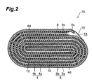
- Fig. 2 is a schematic cross sectional view when the wound-type lithium ion secondary battery shown in Fig. 1 is cut along the II-II line of Fig. 1 .
- Fig. 3 is a perspective view showing a step of a method for manufacturing the wound-type lithium ion secondary battery shown in Fig. 1 .
- Fig. 4 is a perspective view showing a step of the method for manufacturing the wound-type lithium ion secondary battery shown in Fig. 1 .
- Fig. 5 is a perspective view showing a step of the method for manufacturing the wound-type lithium ion secondary battery shown in Fig. 1 .
- a wound-type lithium ion secondary battery (hereinafter, denoted as a "battery") 2, which is a preferred embodiment of the present invention, comprises a substantially elliptic wound body 10 formed by winding a belt-like positive electrode 4 and a belt-like negative electrode 6 so as to sandwich a belt-like separator 8 therebetween, as shown in Figs. 1 , 2 .
- the wound body 10 comprising the positive electrode 4 and the negative electrode 6 having a lead 12 connected thereto, respectively, is enclosed in an outer package (not illustrated) of the battery 2.
- the maximum length L in the longitudinal direction of the wound body 10 is in the order of 16 to 18 mm
- the maximum length H in the shorter side direction of the wound body 10 is in the order of 1.0 to 1.3 mm
- the width W of the wound body 10 is in the order of 13.5 to 15 mm.
- the positive electrode 4 comprises a belt-like positive electrode current collector 4a and a positive electrode active material layer 4b covering both sides of the positive electrode current collector 4a, as shown in Fig. 2 .
- the negative electrode 6 comprises a belt-like negative electrode current collector 6a and a negative electrode active material layer 6b covering both sides of the negative electrode current collector 6a.
- the positive electrode active material layer 4b covers the whole area on both sides of the positive electrode current collector 4a while the negative electrode active material layer 6b covers the whole area on both sides of the negative electrode current collector 6a.
- both sides of the one-layer positive electrode 4 adjoin the negative electrode 6 via the separator 8, respectively, and both sides of the one-layer negative electrode 6 adjoin the positive electrode 4 via the separator, respectively.
- the end of the negative electrode 6 is interposed in a U-shaped portion which the positive electrode 4 positioned on the center side of the wound body 10 forms, while the end of the positive electrode 4 is interposed in a U-shaped portion which the negative electrode 6 positioned on the center side of the wound body 10 forms, and thus the positive electrode 4 and the negative electrode 6 are arranged in symmetrical positions on the center side.
- both sides of an end 4d on the center side of the wound body of the one-layer positive electrode 4 adjoin the negative electrode 6 via the separator 8, respectively, and both sides of an end 6d on the center side of the wound body of the one-layer negative electrode 6 adjoin the positive electrode 4 via the separator, respectively.
- the after-mentioned winding core portion 16 is arranged on the center side of the wound body 10.
- both sides of the positive electrode 4 are opposed to the negative electrode 6, respectively, and also both sides of the negative electrode 6 are opposed to the positive electrode 4, respectively, and thus a portion where the positive electrode 4 and the negative electrode 6 are not opposed to each other will not be formed on the center side of the wound body 10.
- a portion where one of the opposing positive electrode and negative electrode lacks the active material is not formed except at the connection position of the lead. For this reason, in this embodiment, the capacity of the battery 2 can be increased as compared with the conventional batteries.
- the end 6c of the negative electrode 6 arranged on the outermost peripheral side extends further in the winding direction (longitudinal direction of the negative electrode 6) of the wound body 10 than the end 4c of the positive electrode 4 arranged on the inner peripheral side. For this reason, a gap is produced between the end 6c of the negative electrode 6 extending in the winding direction of the wound body 10 and the outer periphery of the wound body 10. Then, the end 6c of the negative electrode 6 extending in the winding direction of the wound body 10 is fixed to the outer peripheral surface of the wound body 10 with an adhesive tape 13 so as to be pushed against the inner peripheral side of the wound body 10.
- the thickness of the adhesive layer of the adhesive tape 13 In order to reliably fix each of the ends 4c, 6c of the positive electrode 4 and the negative electrode 6 to the outer peripheral surface of the wound body 10, the thickness of the adhesive layer of the adhesive tape 13 needs to be secured. On the other hand, it is preferable to thin the thickness of the adhesive layer of the adhesive tape 13 in order to flatten the outer periphery of the wound body 10, but there is a limit in thinning the adhesive tape 13 because the thinner adhesive layer will decrease the adhesion force of the adhesive tape 13. In this embodiment, since the adhesive tape 13 is partly pushed into the gap 14 between the end 6c of the negative electrode 6 and the outer periphery of the wound body 10, the outer periphery of the wound body 10 can be made substantially flat even if the thick adhesive tape 13 is used.
- a current collector used in the known electrochemical device can be used, and for example, a belt-like shaped copper, aluminum, nickel, or the like can be used.
- the positive electrode active material layer 4b contains a positive active material (cathode active material), a conductive auxiliary agent, a binder, and the like.
- the cathode active material is not limited in particular as long as it allows the occlusion and release of lithium ions, the desorption and insertion (intercalation) of lithium ions, or the doping and undoping of lithium ions and counter anions (e.g., PF 6 - ) of the lithium ions to be carried out reversibly, and the well-known electrode active materials can be used.
- M is one or more kinds of elements selected from Al, Mg, Nb, Ti, Cu, Zn
- the negative electrode active material layer 6b contains a negative electrode active material (anode active material), a conductive auxiliary agent, a binder, and the like.
- the anode active material is not limited in particular as long as it allows the occlusion and release of lithium ions, the desorption and insertion (intercalation) of lithium ions, or the doping and undoping of lithium ions and counter anions (e.g., PF 6 - ) of the lithium ions to be carried out reversibly, and the well-known anode active materials can be used.
- Such an active material include a carbon material such as natural graphite, synthetic graphite, graphitization resistant carbon, graphitizable carbon, or low-temperature calcination carbon, a metal such as Al, Si, or Sn, that can combine with lithium, an amorphous compound containing an oxide such as SiO, SiO x , SiO 2 , or SnO 2 , as the principal component, lithium titanate (Li 4 Ti 5 O 12 ), and TiO 2 .
- the carbon material is preferable, and a carbon material whose interlayer distance d 002 is from 0.335 to 0.338 nm and in which the crystallite size Lc 002 is from 30 to 120 nm is more preferable.
- Examples of carbon materials which satisfy these conditions include synthetic graphite, MCF (mesocarbon fiber), and MCMB (mesocarbon microbeads). Note that the above-described interlayer distance d 002 and crystallite size Lc 002 can be determined by X-ray diffraction.
- the one formed from an electrically insulating porous body can be used.
- the electrically insulating porous body include single-layer or laminated films composed of polyethylene, polypropylene, or polyolefin; stretched films of mixtures of resins; or fiber nonwoven cloth composed of one or more kinds of material selected from the group consisting of cellulose, polyester, and polypropylene.
- the thickness of the positive electrode current collector 4a or the negative electrode current collector 6a is in the order of 6 to 25 ⁇ m.
- the thickness of the positive electrode active material layer 4b or the negative electrode active material layer 6b is in the order of 20 to 200 ⁇ m.
- the thickness of the separator 8 is in the order of 0.05 to 10 ⁇ m.
- the thickness of the adhesive tape 13 is in the order of 30 ⁇ m.
- the wound body 10 is formed using one belt-like positive electrode 4, one belt-like negative electrode 6, and one belt-like separator 8.
- the longitudinal length of the positive electrode 4 is in the order of 9 to 12 cm, the shorter-side length thereof is in the order of 1.0 to 1.5 cm, and the thickness thereof is in the order of 40 to 80 ⁇ m.
- the dimensions of the negative electrode 6 are almost the same as those of the positive electrode 4.
- the longitudinal length of the separator 8 is preferably no less than two times the longitudinal length of the positive electrode 4. This allows both sides of the positive electrode 4 to be covered reliably with the separator 8. The shorter side length of the separator 8 is almost the same as that of the positive electrode 4 and the negative electrode 6.
- the belt-like separator 8 is folded in the longitudinal direction. Note that the separator 8 is preferably folded at the center portion in the longitudinal direction. This allows both sides of the positive electrode 4 to be covered uniformly with the separator 8.
- the belt-like positive electrode 4 is sandwiched by the separator 8 from the longitudinal end 4d side, and both sides of the positive electrode 4 were covered with the separator 8. Note that in sandwiching the positive electrode 4 by the separator 8, the tip of the end 4d of the positive electrode 4 is pushed against the folding line of the separator 8. Note that the longitudinal end 4d of the positive electrode 4 is the end opposite to the end 4c of the positive electrode 4 arranged on the outer peripheral side of the wound body 10.
- the longitudinal end 6d side of the negative electrode 6 is folded in the longitudinal direction of the negative electrode 6. Then, the end 4d of the positive electrode 4 sandwiched by the separator 8 is sandwiched by the end 6d of the negative electrode 6 to form the winding core portion 16 comprising the end 4d of the positive electrode 4 sandwiched by the separator 8, and the end 6d of the negative electrode 6, as shown in Fig. 5 .
- the longitudinal end 6d of the negative electrode 6 is the end opposite to the end 6c of the negative electrode 6 arranged on the outer peripheral side of the wound body 10. Moreover, as shown in Fig.
- the positive electrode 4, both sides of which are covered with the separator 8, and the negative electrode 6 are wound around the winding core portion 16 at the same time. Note that in starting the winding, the positive electrode 4, both sides of which are covered with the separator 8, and the negative electrode 6 are folded back to the winding core portion 16 side along a tip 6f (a folding line 18 parallel to the shorter side of the winding core portion 16) of the end 6d of the negative electrode 6.
- the positive electrode 4 sandwiched by the separator 8 is sandwiched by the end 4d of the negative electrode 6 to form the winding core portion 16
- the positive electrode 4 both sides of which are covered with the active material, and the negative electrode 6 can be opposed to each other also in the winding core portion 16. That is, in the battery 2 obtained by the above-described manufacturing method, a portion where the positive and negative electrodes are not opposed to each other will not be formed on the center side of the wound body 10 unlike the conventional batteries.
- a portion where one of the opposing positive electrode 4 and negative electrode 6 lacks the active material is not formed except at the connection position of the lead 12. For this reason, in this embodiment, the battery 2 having a large capacity as compared with the conventional batteries can be manufactured.
- the winding core portion 16 comprising parts of the each positive electrode 4, negative electrode 6, and separator 8 is formed, and subsequently, the positive electrode 4, the negative electrode 6, and the separator 8 are wound around the winding core portion at the same time. That is, in this embodiment, since the alignment between the positive electrode 4, the negative electrode 6, and the separator 8 is carried out in forming the winding core portion 16 prior to winding these electrodes and separator, the alignment between the positive electrode 4 and the negative electrode 6 does not need to be carried out in the course of the winding unlike in the related arts, and the relative position between the positive electrode 4 and the negative electrode 6 is unlikely to deviate from a desired position.
- the dimensions and shape of the wound body 10 are defined by the dimensions and shape of the winding core portion 16, and the dimensions and shape of the winding core portion 16 are defined by the longitudinal length 6e of the end 6d of the negative electrode 6 to be folded and the shorter side length of the negative electrode 6 (see Figs. 4 and 5 ). Since the longitudinal length 6e of the end 6d of the negative electrode 6 and the shorter side length of the negative electrode 6 can be set easily and precisely, the dimensions and shape of the wound body 10 also can be set easily and precisely. For example, as the longitudinal length 6e of the end 6d of the negative electrode 6 is lengthened further, the maximum length L in the longitudinal direction of the wound body 10 becomes longer and accordingly the flat wound body 10 can be formed.
- the winding core since the winding core is not required separately from the positive electrode 4, the negative electrode 6, and the separator 8, the winding core does not need to be taken out from the wound body 10 and also a deformation of the wound body 10 associated with taking out the winding core will not occur either.
- the wound-type electrochemical device of the present invention is not limited to the lithium ion secondary battery but may be secondary batteries other than the lithium ion secondary battery such as a metal lithium secondary battery, a lithium capacitor, or an electric double layer capacitor.
- the electrochemical device other than the lithium ion secondary battery as the electrode active material the one suitable for the respective electrochemical devices may be used.
- the electric double layer capacitor for example, as the active material contained in a cathode active material-containing layer and an anode active material-containing layer, acetylene black, graphite, black lead, activated carbon, and the like are used.
- an electrolytic solution for example, the one having a quarternary ammonium salt such as tetraethylammonium tetrafluoroborate dissolved in an organic solvent, such as a propylene carbonate, a diethylene carbonate, or acetonitrile is used.
- wound-type electrochemical device of the present invention can be used also for applications, such as the power supplies for a self-propelled micromachine or an IC card, and the distributed power supplies arranged on or inside a printed circuit board.
Landscapes
- Engineering & Computer Science (AREA)
- Manufacturing & Machinery (AREA)
- Chemical & Material Sciences (AREA)
- Chemical Kinetics & Catalysis (AREA)
- Electrochemistry (AREA)
- General Chemical & Material Sciences (AREA)
- Secondary Cells (AREA)
- Electric Double-Layer Capacitors Or The Like (AREA)
Abstract
Description
- The present invention relates to a wound-type electrochemical device, and a method for manufacturing the wound-type electrochemical device.
- In recent years, with the reduction in size, the reduction in thickness, and the increase in output power of portable electronic devices, there has been a need for the reduction in size, the reduction in thickness, and the increase in output power of a battery used as the power supply of the portable electronic devices. As such a battery, for example, a wound-type battery comprising a wound body formed by spirally winding a positive electrode and a negative electrode with a separator sandwiched therebetween is used (see Japanese patent laid-open No.
2000-77091 2006-278143 - In manufacturing an elliptic cylindrical wound-type battery (a non-cylindrical wound-type battery) as shown in the above-described Japanese patent laid-open No.
2000-77091 2006-278143 - However, in forming the wound body using a winding core different from the positive electrode, the negative electrode, and the separator as shown in the above-described Japanese patent laid-open No.
2000-77091 Figs. 2 ,4 and the like of the above-described Japanese patent laid-open No.2000-77091 - Moreover, if only a part of the end of one of the electrodes is wound around the winding core and subsequently the remainder of the one of the electrodes and the other one of the electrodes are wound, then a relative position between the positive and negative electrodes is likely to deviate from a desired position in aligning the positive and negative electrodes. Therefore, the portion where the positive and negative electrodes are not opposed to each other is formed and thereby the capacity of the wound-type battery tends to decrease, or the dimensions or the shape of the obtained wound body tends to deviate from a desired specification.
- Furthermore, in the battery shown in the above-described Japanese patent laid-open No.
2000-77091 - Moreover, as shown in the above-described Japanese patent laid-open No.
2006-278143 2000-77091 Fig. 2 and the like in the above-described Japanese patent laid-open No.2006-278143 2006-278143 - The present invention has been made in view of the problems the above-described prior arts have. It is an object of the present invention to provide a wound-type electrochemical device capable of increasing the capacity and a method for manufacturing the wound-type electrochemical device capable of increasing the capacity of the obtained wound-type electrochemical device as well as suppressing the deviation in the dimensions of the wound-type electrochemical device or the deformation of the shape thereof.
- In order to achieve the above-described object, a wound-type electrochemical device of the present invention comprises a wound body formed by winding a belt-like positive electrode and a belt-like negative electrode, each of the electrodes being a current collector having an active material layer formed on both sides thereof, so as to sandwich a belt-like separator therebetween, wherein both sides of an end on a center side of the wound body of the positive electrode adjoin the negative electrode via the separator, respectively, while both sides of an end on the center side of the wound body of the negative electrode adjoin the positive electrode via the separator, respectively.
- In the above-described invention, also on the center side of the wound body, both sides of the positive electrode are opposed to the negative electrode, respectively, and both sides of the negative electrode are opposed to the positive electrode, respectively, and thus a portion where the positive and negative electrodes are not opposed to each other will not be formed on the center side of the wound body unlike the conventional batteries. That is, in the present invention, the opposing area of the positive and negative electrodes can be increased as compared with that of the conventional batteries. Therefore, in the present invention, the capacity can be increased as compared with that of the conventional batteries.
- In the above-described invention, of the ends on the outer peripheral side of the wound body of the positive and negative electrodes, the end on the outer peripheral side of the wound body arranged on an outermost peripheral side preferably extends further in a winding direction of the wound body than the end on the outer peripheral side of the wound body arranged on an inner peripheral side.
- By fixing the end on the outer peripheral side of the wound body arranged on the outermost peripheral side, the end extending in the winding direction of the wound body, to the outer peripheral surface of the wound body in such a way to press the end against the inner peripheral side, a step in the outer peripheral surface of the wound body at the ends on the outer peripheral side of the wound body of the positive and negative electrodes is reduced, and the outer periphery of the wound body is flattened, and thus the wound body can be accommodated easily in the outer package of the electrochemical device. On the other hand, in the conventional wound bodies, since the end on the outer peripheral side of the wound body arranged on the outermost peripheral side does not extend further in the winding direction of the wound body than the end on the outer peripheral side of the wound body arranged on the inner peripheral side, it is difficult to reduce the step in the outer peripheral surface of the wound body at the ends on the outer peripheral side of the wound body of the positive and negative electrodes, and also a step caused by the thickness of a fixing member, such as an adhesive tape, for fixing the end on the outer peripheral side to the outer peripheral surface of the wound body is likely to occur. For this reason, in the conventional wound bodies, irregularities are formed in the outer peripheral surface, and the dimensions and shapes of the wound body do not match with those of the outer package, and as a result, the wound body might not be accommodated in the outer package. But, in the present invention, the occurrence of these problems can be suppressed.
- A method for manufacturing the wound-type electrochemical device of the present invention comprises: a step of folding a belt-like separator in a longitudinal direction of the separator, and sandwiching either a belt-like positive electrode or a belt-like negative electrode, the electrode being a current collector having an active material layer formed on both sides thereof, by the separator from a longitudinal end side of the one of the electrodes, thereby covering both sides of the one of the electrodes with the separator; a step of folding a longitudinal end side of the other one of the positive electrode or the negative electrode in a longitudinal direction of the other one of the electrodes, sandwiching an end of the one of the electrodes, which is sandwiched by the separator, by the end of the other one of the electrodes, and thus forming a winding core portion having the end of the one of the electrodes sandwiched by the separator and the end of the other one of the electrodes; and a step of winding the one of the electrodes, both sides of which are covered with the separator, and the other one of the electrodes around the winding core portion, and thus forming a wound body.
- In the above-described invention, since the winding core portion is formed by sandwiching the end of one of the electrodes, which is sandwiched by the separator, through the use of the end of the other one of the electrodes, the positive and negative electrodes can be opposed to each other also in the winding core portion. Therefore, in the wound-type electrochemical device obtained by the present invention, a portion where the positive and negative electrodes are not opposed to each other will not be formed except at the connection position of a lead. Therefore, in the present invention, a wound-type electrochemical device having a large capacity as compared with the conventional batteries can be manufactured.
- Moreover, in the above-described invention, first, a winding core portion comprising the respective parts of the positive electrode, negative electrode, and separator is formed, and subsequently, the positive electrode, the negative electrode, and the separator are wound around the winding core portion at the same time. That is, in the present invention, since the alignment between the positive electrode, the negative electrode, and the separator is carried out in forming the winding core portion prior to winding these, the alignment between the positive electrode, the negative electrode, and the separator does not need to be carried out in the course of the winding unlike in the conventional arts, and thus the relative position between the positive and negative electrodes is unlikely to deviate from a desired position. Therefore, in the present invention, a portion where the positive and negative electrodes are not opposed to each other is unlikely to be formed, a decrease in the capacity of the wound-type electrochemical device can be suppressed, and the dimensions or the shape of the obtained wound body can be suppressed from deviating from a desired specification.
- Furthermore, in the above-described invention, the dimensions and shape of the wound body are defined by those of the winding core portion, and the dimensions and shape of the winding core portion are defined by those of the end of the other one of the electrodes to be folded. Since the dimensions and shape of the end of the other one of the electrodes to be folded can be set easily and precisely, the dimensions and shape of the wound body can be also set easily and precisely.
- Moreover, in the above-described invention, since the winding core is not required separately from the positive electrode, the negative electrode, and the separator, the winding core does not need to be taken out from the wound body, and thus a deformation of the wound body associated with taking out the winding core will not occur, either.
- In the method for manufacturing the wound-type electrochemical device of the present invention described above, the longitudinal length of the separator is preferably no less than two times the longitudinal length of at least either the positive electrode or the negative electrode.
- This allows both sides of the belt-like positive electrode or negative electrode to be covered reliably with the belt-like separator.
- In the method for manufacturing the wound-type electrochemical device of the present invention described above, in the step of covering both sides of the one of the electrodes with the separator, it is preferable that at the center portion in the longitudinal direction of the separator, the separator be folded in the longitudinal direction of the separator and that the one of the electrodes be sandwiched by the separator from the longitudinal end side of the one of the electrodes, thereby both sides of the one of the electrodes be covered with the separator.
- This allows both sides of the one of the electrodes to be covered uniformly with the separator.
- According to the present invention, a wound-type electrochemical device capable of increasing the capacity can be provided. Moreover, according to the present invention, a method for manufacturing the wound-type electrochemical device capable of increasing the capacity of the obtained wound-type electrochemical device and suppressing the deviation in the dimensions or the deformation of the shape of the wound-type electrochemical device can be provided.
-
Fig. 1 is a perspective view showing a wound-type lithium ion secondary battery which is a preferred embodiment of a wound-type electrochemical device of the present invention.Fig. 2 is a schematic cross sectional view when the wound-type lithium ion secondary battery shown inFig. 1 is cut along the II-II line ofFig. 1 .Fig. 3 is a perspective view showing a step of a method for manufacturing the wound-type lithium ion secondary battery shown inFig. 1 .Fig. 4 is a perspective view showing a step of the method for manufacturing the wound-type lithium ion secondary battery shown inFig. 1 .Fig. 5 is a perspective view showing a step of the method for manufacturing the wound-type lithium ion secondary battery shown inFig. 1 . - Hereinafter, a preferred embodiment of the present invention will be described in detail with reference to the accompanying drawings. Note that, in the drawings, the same reference numeral is given to the same or equivalent portion to omit the duplicating description. Moreover, unless otherwise noted, the positional relationship of the up, down, left, right, and the like shall be based on the positional relationship shown in the drawings. Furthermore, the dimension ratios in the drawings are not limited to the illustrated ratios.
- A wound-type lithium ion secondary battery (hereinafter, denoted as a "battery") 2, which is a preferred embodiment of the present invention, comprises a substantially
elliptic wound body 10 formed by winding a belt-likepositive electrode 4 and a belt-likenegative electrode 6 so as to sandwich a belt-like separator 8 therebetween, as shown inFigs. 1 ,2 . Thewound body 10 comprising thepositive electrode 4 and thenegative electrode 6 having alead 12 connected thereto, respectively, is enclosed in an outer package (not illustrated) of the battery 2. - The maximum length L in the longitudinal direction of the
wound body 10 is in the order of 16 to 18 mm, the maximum length H in the shorter side direction of thewound body 10 is in the order of 1.0 to 1.3 mm, and the width W of thewound body 10 is in the order of 13.5 to 15 mm. - The
positive electrode 4 comprises a belt-like positive electrodecurrent collector 4a and a positive electrodeactive material layer 4b covering both sides of the positive electrodecurrent collector 4a, as shown inFig. 2 . Thenegative electrode 6 comprises a belt-like negative electrodecurrent collector 6a and a negative electrodeactive material layer 6b covering both sides of the negativeelectrode current collector 6a. - Higher coverage factors of the positive electrode
active material layer 4b on both sides of the positive electrodecurrent collector 4a and the negative electrodeactive material layer 6b on both sides of the negativeelectrode current collector 6a are preferred, respectively. The higher each of the coverage factors, the larger the capacity of the battery 2 becomes. In this embodiment, except a portion where thelead 12 connected to thepositive electrode 4 and thenegative electrode 6, respectively, is placed, the positive electrodeactive material layer 4b covers the whole area on both sides of the positiveelectrode current collector 4a while the negative electrodeactive material layer 6b covers the whole area on both sides of the negative electrodecurrent collector 6a. - In the
wound body 10, both sides of the one-layerpositive electrode 4 adjoin thenegative electrode 6 via theseparator 8, respectively, and both sides of the one-layernegative electrode 6 adjoin thepositive electrode 4 via the separator, respectively. Moreover, the end of thenegative electrode 6 is interposed in a U-shaped portion which thepositive electrode 4 positioned on the center side of thewound body 10 forms, while the end of thepositive electrode 4 is interposed in a U-shaped portion which thenegative electrode 6 positioned on the center side of thewound body 10 forms, and thus thepositive electrode 4 and thenegative electrode 6 are arranged in symmetrical positions on the center side. That is, both sides of anend 4d on the center side of the wound body of the one-layerpositive electrode 4 adjoin thenegative electrode 6 via theseparator 8, respectively, and both sides of anend 6d on the center side of the wound body of the one-layernegative electrode 6 adjoin thepositive electrode 4 via the separator, respectively. Note that the after-mentioned windingcore portion 16 is arranged on the center side of thewound body 10. - In this embodiment, also on the center side of the
wound body 10, both sides of thepositive electrode 4 are opposed to thenegative electrode 6, respectively, and also both sides of thenegative electrode 6 are opposed to thepositive electrode 4, respectively, and thus a portion where thepositive electrode 4 and thenegative electrode 6 are not opposed to each other will not be formed on the center side of thewound body 10. Moreover, a portion where one of the opposing positive electrode and negative electrode lacks the active material is not formed except at the connection position of the lead. For this reason, in this embodiment, the capacity of the battery 2 can be increased as compared with the conventional batteries. - As shown in
Fig. 2 , of anend 4c (end on the outer peripheral side of the wound body) of thepositive electrode 4 and anend 6c (end on the outer peripheral side of the wound body) of thenegative electrode 6 arranged on the outer peripheral side of thewound body 10, theend 6c of thenegative electrode 6 arranged on the outermost peripheral side extends further in the winding direction (longitudinal direction of the negative electrode 6) of thewound body 10 than theend 4c of thepositive electrode 4 arranged on the inner peripheral side. For this reason, a gap is produced between theend 6c of thenegative electrode 6 extending in the winding direction of thewound body 10 and the outer periphery of thewound body 10. Then, theend 6c of thenegative electrode 6 extending in the winding direction of thewound body 10 is fixed to the outer peripheral surface of thewound body 10 with anadhesive tape 13 so as to be pushed against the inner peripheral side of thewound body 10. - By fixing the
end 6c of thenegative electrode 6, which extends in the winding direction of thewound body 10, to the outer peripheral surface of thewound body 10 with theadhesive tape 13 so as to be pushed against the inner peripheral side of thewound body 10, theend 6c of thenegative electrode 6 and theadhesive tape 13 are partly pressed into agap 14. For this reason, a step in the outer peripheral surface of thewound body 10 in each of theends positive electrode 4 and thenegative electrode 6 is reduced, and the outer periphery of thewound body 10 becomes substantially flat, and thus thewound body 10 can be accommodated easily in the outer package of the battery 2. - In order to reliably fix each of the
ends positive electrode 4 and thenegative electrode 6 to the outer peripheral surface of thewound body 10, the thickness of the adhesive layer of theadhesive tape 13 needs to be secured. On the other hand, it is preferable to thin the thickness of the adhesive layer of theadhesive tape 13 in order to flatten the outer periphery of thewound body 10, but there is a limit in thinning theadhesive tape 13 because the thinner adhesive layer will decrease the adhesion force of theadhesive tape 13. In this embodiment, since theadhesive tape 13 is partly pushed into thegap 14 between theend 6c of thenegative electrode 6 and the outer periphery of thewound body 10, the outer periphery of thewound body 10 can be made substantially flat even if the thickadhesive tape 13 is used. - In the conventional wound bodies, since the end on the outer peripheral side of the wound body arranged on the outermost peripheral side does not extend further in the winding direction of the wound body than the end on the outer peripheral side of the wound body arranged on the inner peripheral side, it is difficult to reduce a step in the outer peripheral surface of the wound body at the ends on the outer peripheral side of the wound body of the positive and negative electrodes, and also a step caused by the thickness of a fixing member for fixing the end on the outer peripheral side of the wound body to the outer peripheral surface of the wound body is likely to occur. For this reason, in the conventional wound bodies, irregularities are formed in the outer peripheral surface, and the dimensions and shapes of the wound body do not match with those of the outer package, and as a result, the wound body might not be accommodated in the outer package. However, in this embodiment, the occurrence of these problems can be suppressed.
- As the positive electrode
current collector 4a and the negative electrodecurrent collector 6a, a current collector used in the known electrochemical device can be used, and for example, a belt-like shaped copper, aluminum, nickel, or the like can be used. - The positive electrode
active material layer 4b contains a positive active material (cathode active material), a conductive auxiliary agent, a binder, and the like. The cathode active material is not limited in particular as long as it allows the occlusion and release of lithium ions, the desorption and insertion (intercalation) of lithium ions, or the doping and undoping of lithium ions and counter anions (e.g., PF6 -) of the lithium ions to be carried out reversibly, and the well-known electrode active materials can be used. The examples of such an active material include cobalt acid lithium (LiCoO2), nickel acid lithium (LiNiO2), lithium manganese spinel (LiMn2O4), and composite metal oxides expressed by the general formula: LiNixCoyMnzMaO2 (x+y+z+a=1, 0≤x≤1, 0≤y≤1, 0≤z≤1, 0≤a≤1, where M is one or more kinds of elements selected from Al, Mg, Nb, Ti, Cu, Zn, and Cr), a lithium vanadium compound (LiV2O5), olivine-type LiMPO4 (where, M denotes one or more kinds of elements selected from Co, Ni, and Mn, or Fe, Mg, Nb, Ti, Al. and Zr, or VO), and lithium titanate (Li4Ti5O12), and other such composite metal oxides. - The negative electrode
active material layer 6b contains a negative electrode active material (anode active material), a conductive auxiliary agent, a binder, and the like. The anode active material is not limited in particular as long as it allows the occlusion and release of lithium ions, the desorption and insertion (intercalation) of lithium ions, or the doping and undoping of lithium ions and counter anions (e.g., PF6 -) of the lithium ions to be carried out reversibly, and the well-known anode active materials can be used. The examples of such an active material include a carbon material such as natural graphite, synthetic graphite, graphitization resistant carbon, graphitizable carbon, or low-temperature calcination carbon, a metal such as Al, Si, or Sn, that can combine with lithium, an amorphous compound containing an oxide such as SiO, SiOx, SiO2, or SnO2, as the principal component, lithium titanate (Li4Ti5O12), and TiO2. Among them, the carbon material is preferable, and a carbon material whose interlayer distance d002 is from 0.335 to 0.338 nm and in which the crystallite size Lc002 is from 30 to 120 nm is more preferable. Examples of carbon materials which satisfy these conditions include synthetic graphite, MCF (mesocarbon fiber), and MCMB (mesocarbon microbeads). Note that the above-described interlayer distance d002 and crystallite size Lc002 can be determined by X-ray diffraction. - As the
separator 8, for example, the one formed from an electrically insulating porous body can be used. Examples of the electrically insulating porous body include single-layer or laminated films composed of polyethylene, polypropylene, or polyolefin; stretched films of mixtures of resins; or fiber nonwoven cloth composed of one or more kinds of material selected from the group consisting of cellulose, polyester, and polypropylene. - The thickness of the positive electrode
current collector 4a or the negative electrodecurrent collector 6a is in the order of 6 to 25 µm. The thickness of the positive electrodeactive material layer 4b or the negative electrodeactive material layer 6b is in the order of 20 to 200 µm. The thickness of theseparator 8 is in the order of 0.05 to 10 µm. The thickness of theadhesive tape 13 is in the order of 30 µm. - In the method for manufacturing the wound-type lithium ion secondary battery (battery 2) according to an embodiment of the present invention, the
wound body 10 is formed using one belt-likepositive electrode 4, one belt-likenegative electrode 6, and one belt-like separator 8. - The
positive electrode 4, where the whole area on both sides of the belt-like positive electrodecurrent collector 4a except the connection portion of thelead 12 is coated with the positive electrodeactive material layer 4b, is prepared. Thenegative electrode 6, where the whole area on both sides of the belt-like negative electrodecurrent collector 6a except the connection portion of thelead 12 is coated with the negative electrodeactive material layer 6b, is prepared. - The longitudinal length of the
positive electrode 4 is in the order of 9 to 12 cm, the shorter-side length thereof is in the order of 1.0 to 1.5 cm, and the thickness thereof is in the order of 40 to 80 µm. The dimensions of thenegative electrode 6 are almost the same as those of thepositive electrode 4. - The longitudinal length of the
separator 8 is preferably no less than two times the longitudinal length of thepositive electrode 4. This allows both sides of thepositive electrode 4 to be covered reliably with theseparator 8. The shorter side length of theseparator 8 is almost the same as that of thepositive electrode 4 and thenegative electrode 6. - In manufacturing the battery 2, first as shown in
Fig. 3 , the belt-like separator 8 is folded in the longitudinal direction. Note that theseparator 8 is preferably folded at the center portion in the longitudinal direction. This allows both sides of thepositive electrode 4 to be covered uniformly with theseparator 8. - Next, the belt-like
positive electrode 4 is sandwiched by theseparator 8 from thelongitudinal end 4d side, and both sides of thepositive electrode 4 were covered with theseparator 8. Note that in sandwiching thepositive electrode 4 by theseparator 8, the tip of theend 4d of thepositive electrode 4 is pushed against the folding line of theseparator 8. Note that thelongitudinal end 4d of thepositive electrode 4 is the end opposite to theend 4c of thepositive electrode 4 arranged on the outer peripheral side of thewound body 10. - Next, as shown in
Fig. 4 , thelongitudinal end 6d side of thenegative electrode 6 is folded in the longitudinal direction of thenegative electrode 6. Then, theend 4d of thepositive electrode 4 sandwiched by theseparator 8 is sandwiched by theend 6d of thenegative electrode 6 to form the windingcore portion 16 comprising theend 4d of thepositive electrode 4 sandwiched by theseparator 8, and theend 6d of thenegative electrode 6, as shown inFig. 5 . Note that thelongitudinal end 6d of thenegative electrode 6 is the end opposite to theend 6c of thenegative electrode 6 arranged on the outer peripheral side of thewound body 10. Moreover, as shown inFig. 4 , when theend 4d of thepositive electrode 4 sandwiched by theseparator 8 is sandwiched by theend 6d of thenegative electrode 6, the tip of theend 4d of thepositive electrode 4 sandwiched by theseparator 8 is pushed against the folding line of thenegative electrode 6. Moreover, as shown inFigs. 4 and5 , thelongitudinal length 6e of theend 6d of thenegative electrode 6 coincides with the longitudinal length of the windingcore portion 16. - Next, as shown in
Fig. 5 , thepositive electrode 4, both sides of which are covered with theseparator 8, and thenegative electrode 6 are wound around the windingcore portion 16 at the same time. Note that in starting the winding, thepositive electrode 4, both sides of which are covered with theseparator 8, and thenegative electrode 6 are folded back to the windingcore portion 16 side along atip 6f (afolding line 18 parallel to the shorter side of the winding core portion 16) of theend 6d of thenegative electrode 6. - After the
positive electrode 4, both sides of which are covered with theseparator 8, and thenegative electrode 6 are wound around the windingcore portion 16 at the same time, as shown inFigs. 1 and2 theend 4c of thepositive electrode 4 and theend 6c of thenegative electrode 6 arranged on the outer peripheral side of thewound body 10 are fixed to the wound body with theadhesive tape 13, and thus thewound body 10 is completed. Thewound body 10 comprising thepositive electrode 4 and thenegative electrode 6 having the lead 12 connected thereto, respectively, is enclosed in the outer package (not illustrated) of the battery 2, and thus the battery 2 is completed. - In this embodiment, since the
end 4d of thepositive electrode 4 sandwiched by theseparator 8 is sandwiched by theend 4d of thenegative electrode 6 to form the windingcore portion 16, thepositive electrode 4, both sides of which are covered with the active material, and thenegative electrode 6 can be opposed to each other also in the windingcore portion 16. That is, in the battery 2 obtained by the above-described manufacturing method, a portion where the positive and negative electrodes are not opposed to each other will not be formed on the center side of thewound body 10 unlike the conventional batteries. Moreover, in the battery 2, a portion where one of the opposingpositive electrode 4 andnegative electrode 6 lacks the active material is not formed except at the connection position of thelead 12. For this reason, in this embodiment, the battery 2 having a large capacity as compared with the conventional batteries can be manufactured. - Moreover, in this embodiment, first, the winding
core portion 16 comprising parts of the eachpositive electrode 4,negative electrode 6, andseparator 8 is formed, and subsequently, thepositive electrode 4, thenegative electrode 6, and theseparator 8 are wound around the winding core portion at the same time. That is, in this embodiment, since the alignment between thepositive electrode 4, thenegative electrode 6, and theseparator 8 is carried out in forming the windingcore portion 16 prior to winding these electrodes and separator, the alignment between thepositive electrode 4 and thenegative electrode 6 does not need to be carried out in the course of the winding unlike in the related arts, and the relative position between thepositive electrode 4 and thenegative electrode 6 is unlikely to deviate from a desired position. For this reason, in this embodiment, a portion where thepositive electrode 4 and thenegative electrode 6 are not opposed to each other is unlikely to be formed, a decrease in the capacity of the battery 2 can be suppressed, and deviations of the dimensions or the shape of the obtained woundbody 10 from a desired specification can be suppressed. - In this embodiment, the dimensions and shape of the
wound body 10 are defined by the dimensions and shape of the windingcore portion 16, and the dimensions and shape of the windingcore portion 16 are defined by thelongitudinal length 6e of theend 6d of thenegative electrode 6 to be folded and the shorter side length of the negative electrode 6 (seeFigs. 4 and5 ). Since thelongitudinal length 6e of theend 6d of thenegative electrode 6 and the shorter side length of thenegative electrode 6 can be set easily and precisely, the dimensions and shape of thewound body 10 also can be set easily and precisely. For example, as thelongitudinal length 6e of theend 6d of thenegative electrode 6 is lengthened further, the maximum length L in the longitudinal direction of thewound body 10 becomes longer and accordingly theflat wound body 10 can be formed. - Moreover, in this embodiment, since the winding core is not required separately from the
positive electrode 4, thenegative electrode 6, and theseparator 8, the winding core does not need to be taken out from thewound body 10 and also a deformation of thewound body 10 associated with taking out the winding core will not occur either. - As described above, a preferred embodiment of the present invention has been described in detail, but the present invention is not limited to the above-described embodiment.
- For example, in the description of the above embodiment, although a case where a wound-type electrochemical device is an lithium ion secondary battery has bee described, the wound-type electrochemical device of the present invention is not limited to the lithium ion secondary battery but may be secondary batteries other than the lithium ion secondary battery such as a metal lithium secondary battery, a lithium capacitor, or an electric double layer capacitor. Note that in the case of the electrochemical device other than the lithium ion secondary battery, as the electrode active material the one suitable for the respective electrochemical devices may be used. Moreover, in the case of the electric double layer capacitor, for example, as the active material contained in a cathode active material-containing layer and an anode active material-containing layer, acetylene black, graphite, black lead, activated carbon, and the like are used. Moreover, as an electrolytic solution, for example, the one having a quarternary ammonium salt such as tetraethylammonium tetrafluoroborate dissolved in an organic solvent, such as a propylene carbonate, a diethylene carbonate, or acetonitrile is used.
- Moreover, the wound-type electrochemical device of the present invention can be used also for applications, such as the power supplies for a self-propelled micromachine or an IC card, and the distributed power supplies arranged on or inside a printed circuit board.
- Moreover, in the battery 2 and the method for manufacturing the battery 2 described above, even if the
positive electrode 4 and thenegative electrode 6 are replaced with each other, the effects of the present invention can be obtained.
Claims (5)
- A wound-type electrochemical device comprising a wound body formed by winding a belt-like positive electrode and a belt-like negative electrode, each of the electrodes being a current collector having an active material layer formed on both sides thereof, so as to sandwich a belt-like separator therebetween, wherein
both sides of an end on a center side of the wound body of the positive electrode adjoin the negative electrode via the separator respectively, while both sides of an end on the center side of the wound body of the negative electrode adjoin the positive electrode via the separator respectively. - The wound-type electrochemical device according to claim 1, wherein of ends on an outer peripheral side of the wound body of the positive and negative electrodes, the end on the outer peripheral side of the wound body arranged on an outermost peripheral side extends further in a winding direction of the wound body than the end on the outer peripheral side of the wound body arranged on an inner peripheral side.
- A method for manufacturing a wound-type electrochemical device, the method comprising steps of:folding a belt-like separator in a longitudinal direction of the separator, sandwiching either a belt-like positive electrode or a belt-like negative electrode, the electrode being a current collector having an active material layer formed on both sides thereof, by the separator from a longitudinal end side of the either one of the electrodes, and thus covering both sides of the one of the electrodes with the separator;folding a longitudinal end side of the other one of the positive electrode or the negative electrode in a longitudinal direction of the other one of the electrodes, sandwiching an end of the one of the electrodes, which is sandwiched by the separator, by the end of the other one of the electrodes, and thus forming a winding core portion having the end of the one of the electrodes sandwiched by the separator and the end of the other one of the electrodes; andwinding the one of the electrodes, both sides of which are covered with the separator, and the other one of the electrodes around the winding core portion, and thus forming a wound body.
- The method for manufacturing the wound-type electrochemical device according to claim 3, wherein a longitudinal length of the separator is no less than two times a longitudinal length of at least either the positive electrode or the negative electrode.
- The method for manufacturing the wound-type electrochemical device according to claim 3 or 4, wherein in the step of covering both sides of the one of the electrodes with the separator, at a center portion in the longitudinal direction of the separator, the separator is folded in the longitudinal direction of the separator, and the one of the electrodes is sandwiched by the separator from the longitudinal end side of the one of the electrodes, thereby both sides of the one of the electrodes are covered with the separator.
Applications Claiming Priority (1)
| Application Number | Priority Date | Filing Date | Title |
|---|---|---|---|
| JP2007340256A JP4683044B2 (en) | 2007-12-28 | 2007-12-28 | Wound-type electrochemical device and method for manufacturing wound-type electrochemical device |
Publications (2)
| Publication Number | Publication Date |
|---|---|
| EP2075869A1 true EP2075869A1 (en) | 2009-07-01 |
| EP2075869B1 EP2075869B1 (en) | 2013-05-01 |
Family
ID=40481972
Family Applications (1)
| Application Number | Title | Priority Date | Filing Date |
|---|---|---|---|
| EP08022036.1A Active EP2075869B1 (en) | 2007-12-28 | 2008-12-18 | Wound-type electrochemical device, and method for manufacturing wound-type electrochemical device |
Country Status (4)
| Country | Link |
|---|---|
| US (1) | US20090169979A1 (en) |
| EP (1) | EP2075869B1 (en) |
| JP (1) | JP4683044B2 (en) |
| CN (1) | CN101471452A (en) |
Cited By (1)
| Publication number | Priority date | Publication date | Assignee | Title |
|---|---|---|---|---|
| EP2541661A4 (en) * | 2010-02-23 | 2016-01-06 | Tdk Corp | Electrochemical device and method for manufacturing electrochemical device |
Families Citing this family (15)
| Publication number | Priority date | Publication date | Assignee | Title |
|---|---|---|---|---|
| US9893377B2 (en) * | 2009-09-25 | 2018-02-13 | Kabushiki Kaisha Toshiba | Nonaqueous electrolyte battery, battery pack and vehicle |
| JP5321501B2 (en) * | 2010-02-23 | 2013-10-23 | Tdk株式会社 | Electrochemical devices |
| CN102332614B (en) * | 2011-09-21 | 2016-04-27 | 东莞新能源科技有限公司 | A kind of winding-structure of lithium ion battery and preparation technology thereof |
| WO2014077887A1 (en) * | 2012-11-19 | 2014-05-22 | Evoqua Water Technologies Llc | Electrochemical separation device |
| JPWO2015129376A1 (en) * | 2014-02-25 | 2017-03-30 | 株式会社東芝 | Winding electrode group and non-aqueous electrolyte battery |
| KR101763576B1 (en) * | 2014-12-22 | 2017-08-01 | 주식회사 엘지화학 | Electrode Assembly Enabling High Capacity with Small Volume and Secondary Battery Comprising the Same |
| JP7061971B2 (en) | 2016-05-20 | 2022-05-02 | キョーセラ・エイブイエックス・コンポーネンツ・コーポレーション | Multicell ultracapacitor |
| US11830672B2 (en) | 2016-11-23 | 2023-11-28 | KYOCERA AVX Components Corporation | Ultracapacitor for use in a solder reflow process |
| JP6873843B2 (en) * | 2016-11-25 | 2021-05-19 | 住友理工株式会社 | Electrostatic transducer and its manufacturing method |
| US10665901B2 (en) * | 2017-02-24 | 2020-05-26 | Panasonic Intellectual Property Management Co., Ltd. | Battery and battery manufacturing method with folded construction |
| JP7046682B2 (en) * | 2018-03-30 | 2022-04-04 | 三洋電機株式会社 | Manufacturing method of non-aqueous electrolyte secondary battery and non-aqueous electrolyte secondary battery |
| KR102301720B1 (en) * | 2018-07-10 | 2021-09-10 | 주식회사 엘지에너지솔루션 | Electrochemical capacitor and manufacturing method thereof |
| JP2020173955A (en) * | 2019-04-10 | 2020-10-22 | 本田技研工業株式会社 | Battery electrode group, winding type battery having the same, and method for manufacturing battery electrode group |
| CN114300755A (en) * | 2020-09-23 | 2022-04-08 | 北京小米移动软件有限公司 | Battery cell, battery pack and electronic equipment |
| CN113383448B (en) * | 2020-09-28 | 2023-02-07 | 宁德新能源科技有限公司 | Battery with a battery cell |
Citations (12)
| Publication number | Priority date | Publication date | Assignee | Title |
|---|---|---|---|---|
| EP0928035A1 (en) | 1998-01-05 | 1999-07-07 | Voltec Pte., Ltd. | Prismatic battery with a bow shaped casing |
| EP0954043A1 (en) * | 1997-11-19 | 1999-11-03 | Mitsubishi Denki Kabushiki Kaisha | Bonding agent for cells and cell using the same |
| EP0959513A1 (en) * | 1997-11-19 | 1999-11-24 | Mitsubishi Denki Kabushiki Kaisha | Lithium ion secondary battery and manufacture thereof |
| JP2000077091A (en) | 1998-08-27 | 2000-03-14 | Mitsubishi Electric Corp | Battery having spiral electrode body and its manufacture |
| US6159253A (en) * | 1998-01-07 | 2000-12-12 | Medtronic, Inc. | Thermally formed tab slots in a separator for a spirally-wound electrochemical cell |
| US6569558B1 (en) * | 1994-03-03 | 2003-05-27 | Wilson Greatbatch Ltd. | Prismatic high rate cell |
| EP1318561A1 (en) * | 2000-08-09 | 2003-06-11 | Matsushita Electric Industrial Co., Ltd. | Coin-shaped battery |
| US6627343B1 (en) * | 1999-11-12 | 2003-09-30 | Ness Capacitor Co., Ltd. | Electric energy storage device |
| EP1416571A1 (en) * | 2001-08-10 | 2004-05-06 | Matsushita Electric Industrial Co., Ltd. | COIN−SHAPED CELL, AND MANUFACTURING METHOD THEREOF |
| US6797429B1 (en) * | 1998-11-06 | 2004-09-28 | Japan Storage Battery Co, Ltd. | Non-aqueous electrolytic secondary cell |
| US20050123829A1 (en) * | 2003-12-04 | 2005-06-09 | Atsushi Fukui | Lithium secondary battery and method for manufacturing the same |
| JP2006278143A (en) | 2005-03-29 | 2006-10-12 | Sanyo Electric Co Ltd | Battery with spiral electrode |
Family Cites Families (7)
| Publication number | Priority date | Publication date | Assignee | Title |
|---|---|---|---|---|
| JPH0574496A (en) * | 1991-09-12 | 1993-03-26 | Asahi Chem Ind Co Ltd | Secondary battery |
| JP3042925B2 (en) * | 1991-11-13 | 2000-05-22 | 東芝電池株式会社 | Battery |
| JP3428448B2 (en) * | 1998-08-21 | 2003-07-22 | 三菱電機株式会社 | Electrode structure and battery using the same |
| JP2000123878A (en) * | 1998-10-15 | 2000-04-28 | Japan Storage Battery Co Ltd | Nonaqueous electrolyte secondary battery |
| JP3851153B2 (en) * | 2001-11-30 | 2006-11-29 | 三洋電機株式会社 | Battery and manufacturing method thereof |
| JP4863636B2 (en) * | 2005-03-29 | 2012-01-25 | 三洋電機株式会社 | Spiral electrode square battery |
| JP4412304B2 (en) * | 2006-05-17 | 2010-02-10 | ソニー株式会社 | Secondary battery |
-
2007
- 2007-12-28 JP JP2007340256A patent/JP4683044B2/en active Active
-
2008
- 2008-12-15 US US12/335,016 patent/US20090169979A1/en not_active Abandoned
- 2008-12-18 EP EP08022036.1A patent/EP2075869B1/en active Active
- 2008-12-29 CN CNA2008101891239A patent/CN101471452A/en active Pending
Patent Citations (12)
| Publication number | Priority date | Publication date | Assignee | Title |
|---|---|---|---|---|
| US6569558B1 (en) * | 1994-03-03 | 2003-05-27 | Wilson Greatbatch Ltd. | Prismatic high rate cell |
| EP0954043A1 (en) * | 1997-11-19 | 1999-11-03 | Mitsubishi Denki Kabushiki Kaisha | Bonding agent for cells and cell using the same |
| EP0959513A1 (en) * | 1997-11-19 | 1999-11-24 | Mitsubishi Denki Kabushiki Kaisha | Lithium ion secondary battery and manufacture thereof |
| EP0928035A1 (en) | 1998-01-05 | 1999-07-07 | Voltec Pte., Ltd. | Prismatic battery with a bow shaped casing |
| US6159253A (en) * | 1998-01-07 | 2000-12-12 | Medtronic, Inc. | Thermally formed tab slots in a separator for a spirally-wound electrochemical cell |
| JP2000077091A (en) | 1998-08-27 | 2000-03-14 | Mitsubishi Electric Corp | Battery having spiral electrode body and its manufacture |
| US6797429B1 (en) * | 1998-11-06 | 2004-09-28 | Japan Storage Battery Co, Ltd. | Non-aqueous electrolytic secondary cell |
| US6627343B1 (en) * | 1999-11-12 | 2003-09-30 | Ness Capacitor Co., Ltd. | Electric energy storage device |
| EP1318561A1 (en) * | 2000-08-09 | 2003-06-11 | Matsushita Electric Industrial Co., Ltd. | Coin-shaped battery |
| EP1416571A1 (en) * | 2001-08-10 | 2004-05-06 | Matsushita Electric Industrial Co., Ltd. | COIN−SHAPED CELL, AND MANUFACTURING METHOD THEREOF |
| US20050123829A1 (en) * | 2003-12-04 | 2005-06-09 | Atsushi Fukui | Lithium secondary battery and method for manufacturing the same |
| JP2006278143A (en) | 2005-03-29 | 2006-10-12 | Sanyo Electric Co Ltd | Battery with spiral electrode |
Cited By (1)
| Publication number | Priority date | Publication date | Assignee | Title |
|---|---|---|---|---|
| EP2541661A4 (en) * | 2010-02-23 | 2016-01-06 | Tdk Corp | Electrochemical device and method for manufacturing electrochemical device |
Also Published As
| Publication number | Publication date |
|---|---|
| EP2075869B1 (en) | 2013-05-01 |
| US20090169979A1 (en) | 2009-07-02 |
| CN101471452A (en) | 2009-07-01 |
| JP4683044B2 (en) | 2011-05-11 |
| JP2009163926A (en) | 2009-07-23 |
Similar Documents
| Publication | Publication Date | Title |
|---|---|---|
| EP2075869B1 (en) | Wound-type electrochemical device, and method for manufacturing wound-type electrochemical device | |
| JP4438863B2 (en) | Winding type electrochemical device and manufacturing method thereof | |
| EP2169744B1 (en) | Non-aqueous electrolyte secondary battery | |
| JP5157244B2 (en) | Electrochemical device and manufacturing method thereof | |
| US9077017B2 (en) | Prismatic cell | |
| JP4623039B2 (en) | Electrochemical element | |
| JP4557001B2 (en) | Electrode for electrochemical device and electrochemical device | |
| JP4075034B2 (en) | Nonaqueous electrolyte battery and manufacturing method thereof | |
| JP4293501B2 (en) | Electrochemical devices | |
| US7855013B2 (en) | Electric double-layer capacitor and method of manufacturing electric double-layer capacitor | |
| US9431680B2 (en) | Electric storage device, electric storage system, and manufacturing method thereof | |
| EP3012898A1 (en) | Secondary battery and electrode production method | |
| CN107851768B (en) | Method for manufacturing electrochemical device | |
| JP2001085042A (en) | Lithium secondary battery and fabrication of wound electrode | |
| US20210020895A1 (en) | Secondary battery and manufacturing method thereof | |
| US20200251783A1 (en) | Secondary battery | |
| KR20240056395A (en) | Elctrode assembly and electrochemical device comprising the same | |
| KR20240056430A (en) | Elctrode assembly and electrochemical device comprising the same | |
| CN114868295A (en) | Nonaqueous electrolyte secondary battery and method for manufacturing same | |
| CN112753111A (en) | Electrode for lithium ion secondary battery, method for producing same, and lithium ion secondary battery | |
| JP2001338695A (en) | Method of manufacturing nonaqueous electrolyte cell |
Legal Events
| Date | Code | Title | Description |
|---|---|---|---|
| PUAI | Public reference made under article 153(3) epc to a published international application that has entered the european phase |
Free format text: ORIGINAL CODE: 0009012 |
|
| 17P | Request for examination filed |
Effective date: 20081218 |
|
| AK | Designated contracting states |
Kind code of ref document: A1 Designated state(s): AT BE BG CH CY CZ DE DK EE ES FI FR GB GR HR HU IE IS IT LI LT LU LV MC MT NL NO PL PT RO SE SI SK TR |
|
| AX | Request for extension of the european patent |
Extension state: AL BA MK RS |
|
| 17Q | First examination report despatched |
Effective date: 20091202 |
|
| AKX | Designation fees paid |
Designated state(s): DE FR GB |
|
| RIC1 | Information provided on ipc code assigned before grant |
Ipc: H01M 10/04 20060101AFI20120914BHEP Ipc: H01M 10/0587 20100101ALI20120914BHEP Ipc: H01M 10/0525 20100101ALN20120914BHEP |
|
| RIC1 | Information provided on ipc code assigned before grant |
Ipc: H01M 10/04 20060101AFI20121029BHEP Ipc: H01M 10/0587 20100101ALI20121029BHEP Ipc: H01M 10/0525 20100101ALN20121029BHEP |
|
| GRAP | Despatch of communication of intention to grant a patent |
Free format text: ORIGINAL CODE: EPIDOSNIGR1 |
|
| GRAS | Grant fee paid |
Free format text: ORIGINAL CODE: EPIDOSNIGR3 |
|
| GRAA | (expected) grant |
Free format text: ORIGINAL CODE: 0009210 |
|
| AK | Designated contracting states |
Kind code of ref document: B1 Designated state(s): DE FR GB |
|
| REG | Reference to a national code |
Ref country code: GB Ref legal event code: FG4D |
|
| REG | Reference to a national code |
Ref country code: DE Ref legal event code: R096 Ref document number: 602008024216 Country of ref document: DE Effective date: 20130627 |
|
| PLBE | No opposition filed within time limit |
Free format text: ORIGINAL CODE: 0009261 |
|
| STAA | Information on the status of an ep patent application or granted ep patent |
Free format text: STATUS: NO OPPOSITION FILED WITHIN TIME LIMIT |
|
| 26N | No opposition filed |
Effective date: 20140204 |
|
| REG | Reference to a national code |
Ref country code: DE Ref legal event code: R097 Ref document number: 602008024216 Country of ref document: DE Effective date: 20140204 |
|
| GBPC | Gb: european patent ceased through non-payment of renewal fee |
Effective date: 20131218 |
|
| REG | Reference to a national code |
Ref country code: FR Ref legal event code: ST Effective date: 20140829 |
|
| PG25 | Lapsed in a contracting state [announced via postgrant information from national office to epo] |
Ref country code: FR Free format text: LAPSE BECAUSE OF NON-PAYMENT OF DUE FEES Effective date: 20131231 Ref country code: GB Free format text: LAPSE BECAUSE OF NON-PAYMENT OF DUE FEES Effective date: 20131218 |
|
| PGFP | Annual fee paid to national office [announced via postgrant information from national office to epo] |
Ref country code: DE Payment date: 20231031 Year of fee payment: 16 |