EP2075848A2 - Optical power for electronic circuits using a single photovoltaic component - Google Patents
Optical power for electronic circuits using a single photovoltaic component Download PDFInfo
- Publication number
- EP2075848A2 EP2075848A2 EP08170876A EP08170876A EP2075848A2 EP 2075848 A2 EP2075848 A2 EP 2075848A2 EP 08170876 A EP08170876 A EP 08170876A EP 08170876 A EP08170876 A EP 08170876A EP 2075848 A2 EP2075848 A2 EP 2075848A2
- Authority
- EP
- European Patent Office
- Prior art keywords
- voltage
- photovoltaic component
- optical power
- circuit
- sensor
- Prior art date
- Legal status (The legal status is an assumption and is not a legal conclusion. Google has not performed a legal analysis and makes no representation as to the accuracy of the status listed.)
- Withdrawn
Links
Images

Classifications
-
- H—ELECTRICITY
- H10—SEMICONDUCTOR DEVICES; ELECTRIC SOLID-STATE DEVICES NOT OTHERWISE PROVIDED FOR
- H10F—INORGANIC SEMICONDUCTOR DEVICES SENSITIVE TO INFRARED RADIATION, LIGHT, ELECTROMAGNETIC RADIATION OF SHORTER WAVELENGTH OR CORPUSCULAR RADIATION
- H10F77/00—Constructional details of devices covered by this subclass
- H10F77/95—Circuit arrangements
- H10F77/953—Circuit arrangements for devices having potential barriers
- H10F77/955—Circuit arrangements for devices having potential barriers for photovoltaic devices
-
- H—ELECTRICITY
- H03—ELECTRONIC CIRCUITRY
- H03F—AMPLIFIERS
- H03F3/00—Amplifiers with only discharge tubes or only semiconductor devices as amplifying elements
- H03F3/04—Amplifiers with only discharge tubes or only semiconductor devices as amplifying elements with semiconductor devices only
- H03F3/08—Amplifiers with only discharge tubes or only semiconductor devices as amplifying elements with semiconductor devices only controlled by light
-
- H—ELECTRICITY
- H04—ELECTRIC COMMUNICATION TECHNIQUE
- H04B—TRANSMISSION
- H04B10/00—Transmission systems employing electromagnetic waves other than radio-waves, e.g. infrared, visible or ultraviolet light, or employing corpuscular radiation, e.g. quantum communication
- H04B10/80—Optical aspects relating to the use of optical transmission for specific applications, not provided for in groups H04B10/03 - H04B10/70, e.g. optical power feeding or optical transmission through water
- H04B10/806—Arrangements for feeding power
- H04B10/807—Optical power feeding, i.e. transmitting power using an optical signal
-
- H—ELECTRICITY
- H02—GENERATION; CONVERSION OR DISTRIBUTION OF ELECTRIC POWER
- H02J—ELECTRIC POWER NETWORKS; CIRCUIT ARRANGEMENTS OR SYSTEMS FOR SUPPLYING OR DISTRIBUTING ELECTRIC POWER; SYSTEMS FOR STORING ELECTRIC ENERGY
- H02J7/00—Circuit arrangements for charging or discharging batteries or for supplying loads from batteries
- H02J7/34—Parallel operation in networks using both storage and other DC sources, e.g. providing buffering
- H02J7/35—Parallel operation in networks using both storage and other DC sources, e.g. providing buffering with light sensitive cells
-
- Y—GENERAL TAGGING OF NEW TECHNOLOGICAL DEVELOPMENTS; GENERAL TAGGING OF CROSS-SECTIONAL TECHNOLOGIES SPANNING OVER SEVERAL SECTIONS OF THE IPC; TECHNICAL SUBJECTS COVERED BY FORMER USPC CROSS-REFERENCE ART COLLECTIONS [XRACs] AND DIGESTS
- Y02—TECHNOLOGIES OR APPLICATIONS FOR MITIGATION OR ADAPTATION AGAINST CLIMATE CHANGE
- Y02E—REDUCTION OF GREENHOUSE GAS [GHG] EMISSIONS, RELATED TO ENERGY GENERATION, TRANSMISSION OR DISTRIBUTION
- Y02E10/00—Energy generation through renewable energy sources
- Y02E10/50—Photovoltaic [PV] energy
- Y02E10/56—Power conversion systems, e.g. maximum power point trackers
Definitions
- This application relates to the field of providing optical power and, more particularly, to the field of providing optical power to electronic components.
- Optical power uses light to run remote, isolated circuits without the need for metallic wires to provide electrical power. It is known to use a custom photovoltaic power converter consisting of a number of photodiodes connected in series to optically power a circuit in response to light impinging on the photodiodes. For example, JDSU of Milpitas, California makes a photovoltaic power converter that can power electronic circuits. A series of photodiodes may be used because a single silicon photodiode may not generate enough voltage (aprox. .7 volts) to power a circuit. The custom converter may be an expensive part and have few sources of manufacture.
- optical power is the providing of power to a sensor in a fuel tank. It is advantageous to mitigate the potential for a fuel tank explosion by eliminating the use of metallic wires in the fuel tank while still providing power to sensors to monitor conditions in the fuel tank, such as pressure. In other instances, it is useful to reduce weight by eliminating metallic wires.
- the use of optical power may result in increased cost due to the need to provide a custom converter with multiple photodiodes to supply sufficient voltage to the sensor or other circuit in the fuel tank.
- an optical power system includes a single photovoltaic component that supplies a first voltage in response to impingement of light on the photovoltaic component.
- a voltage booster is coupled to the photovoltaic component and receives the first voltage from the photovoltaic component and generates a second voltage that is greater than the first voltage.
- the photovoltaic component may be a light emitting diode that may include a fiber optic connection.
- the voltage booster may be a charge pump type DC-to-DC step-up converter and/or an inductor type DC-to-DC step-up converter.
- the inductor type DC-to-DC step-converter may operate for a time after the first voltage is turned off.
- the first voltage may be less than 3 volts and the second voltage is greater than 3 volts.
- the voltage booster may include a digital output that indicates a state of the light impinging on the photovoltaic component.
- a sensor system includes a single photovoltaic component that supplies a first voltage in response to impingement of light on the photovoltaic component.
- a voltage booster is coupled to the photovoltaic component that receives the first voltage from the photovoltaic component and supplies a second voltage that is greater than the first voltage.
- a circuit may be coupled to the voltage booster that receives the second voltage, wherein the second voltage is sufficient to power the circuit.
- the photovoltaic component may be a light emitting diode.
- the circuit may be a sensor such as a fuel tank pressure sensor.
- the circuit may include a communication system, and the communication system may recognize a light modulated communication signal.
- the photovoltaic component, the voltage booster and the circuit may all be disposed in a housing.
- the voltage booster may be a charge pump type DC-to-DC step-up converter and/or an inductor type DC-to-DC step-up converter.
- the inductor type DC-to-DC step-converter may operate for a time after the first voltage is turned off.
- the first voltage may be less than 3 volts and the second voltage is greater than 3 volts, and wherein the circuit requires at least approximately 3 volts to be powered.
- a method for optically powering a circuit includes positioning a single photovoltaic component to receive impinging light, wherein the photovoltaic component supplies a first voltage in response to the impinging light.
- a voltage booster may be coupled to the photovoltaic component, wherein the voltage booster receives the first voltage and supplies a second voltage that is greater than the first voltage.
- the circuit may be coupled to the voltage booster, wherein the circuit is powered by the second voltage.
- the photovoltaic component may be a light emitting diode.
- the circuit may be a fuel tank sensor.
- the impinging light may be modulated to communicate with the circuit.
- a light emitting diode (LED) and DC-to-DC voltage booster may be used in an optical power system in place of a custom voltage converter.
- the LED and DC-to-DC voltage booster components may be off the-shelf components that are commonly available.
- An LED may normally be used to emit light but may also be used to generate electric power when exposed to illuminating light, similar to a photodiode but capable of generating a higher voltage (e.g., a little over 1 volt).
- Circuits are known for taking advantage of the photo-voltaic voltage of an LED in response to light impingement, such as for light sensors, and which may be used in connection with the system described herein.
- the voltage from the LED although generally still insufficient to power most circuits, is high enough to run a DC-to-DC voltage booster, for example, that is commonly available to boost the voltage of single cell batteries.
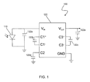
- FIG. 1 is a schematic diagram showing an optical power system 100 according to an embodiment of the system described herein.
- An LED 110 is shown coupled to a DC-to-DC voltage booster 120.
- the LED 110 supplies a voltage to the V IN terminal of the voltage booster 120 in response to illuminating light impinging upon the LED.
- the LED may supply a voltage of a little more than 1 volt to the V IN terminal.
- the LED may be from the HFBR-14xx series by Agilent Technologies of Santa Clara, CA, such as an HFBR-1414 component that includes a fiber optic connection.
- the voltage booster 120 receives the input voltage at the V IN terminal from the LED 110 and supplies a boosted voltage at the V OUT terminal.
- the voltage booster 120 may supply an output voltage of 3.3 volts that may be sufficient to power a circuit.
- the output voltage from the booster 120 may be sufficient to power a sensor, such as a pressure sensor in a fuel tank.
- sensors such as capacitance, temperature, ultrasonic, and resistance sensors that may measure fuel height, volume, density, flow, contamination, etc.
- the voltage booster 120 may be a regulated charge pump DC/DC step-up converter available from Linear Technology of Milpitas, CA, such as an LTC1502-3.3 component.
- External capacitors may be required for appropriate operation of the voltage booster 120, such as the five external capacitors 122a-e that are connected to the V IN , V OUT , C1 + , C1 - , C3 + , C3 - and C2 terminals as shown in FIG. 1 .
- the capacitors may range from 1 ⁇ F to 10 ⁇ F.
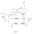
- FIG. 2 is a schematic diagram showing an optical power system 200 according to another embodiment of the system described herein.
- An LED 210 is shown coupled to a DC-to-DC voltage booster 220.
- the LED 210 supplies a voltage to V IN of the voltage booster 220 in response to illuminating light impinging upon the LED and may be similar to the LED 110 discussed elsewhere herein.
- the LED may supply a voltage of a little more than 1 volt to the V IN terminal.
- the voltage booster 220 may be an inductor-type voltage booster that may be more efficient than a charge pump DC/DC booster such as is shown in connection with FIG. 1 .
- the voltage booster 220 receives an input voltage at the V IN terminal and supplies an output voltage at the V OUT terminal that may be sufficient to power a circuit, such as a sensor.
- the voltage booster 220 is a micropower synchronous step-up DC/DC converter available from Linear Technologies of Milpitas, CA, such as an LTC3525L-3 component that outputs 3 volts.
- the voltage booster 220 may include external components for appropriate operation, including two capacitors 222a, 222b and an inductor 222c, as shown in FIG. 2 .
- the inductor 222c is shown coupled across the V IN terminal and switch (SW) input terminal.
- the voltage booster 220 may also include a shutdown control (SHDN) terminal that may be used to turn the voltage booster 220 on and off.
- SHDN shutdown control
- the voltage booster 220 includes a delayed start-up feature that allows input energy to build up before the voltage booster is turned-on.
- the delay in start-up may occur since an inductor type booster may require a relatively large start-up current.
- the illuminating light may be turned off for short periods without interrupting the power output of the voltage booster 220. Modulation of the illuminating light may be used to communicate with the sensor or other circuit being powered, as further discussed elsewhere herein.
- the voltage booster 220 may also include a digital output that indicates the state of the illuminating light.
- FIG. 3 is a schematic illustration showing a sensor system 300 that may include an optical power system 305 and a sensor 330, and/or other circuit, according to an embodiment of the system described herein.
- the optical power system 305 may include an LED 310 and a voltage booster 320 that may operate similarly to components 110, 210, 120, 220 described elsewhere herein.
- the optical power system 305 may be coupled to the sensor 330, and the optical power system 305 and sensor 330 may be disposed in a housing 302.
- the housing 302 of the sensor system 300 may provide for an optical path 304 that permits illuminating light to be received at the LED 310.
- the optical path 304 to the LED 310 may be via a fiber optic communication link.
- connection for the fiber optic communication link may be integrated with the LED 310.
- Modulation of the illuminating light may be used to communicate with the sensor 330.
- the sensor 330 may include a communication system that recognizes a light modulated signal.
- Other communication systems may also be used in connection with the system described herein, including, for example, wireless communication in which the sensor 330 receives a wirelessly transmitted signal and/or wirelessly transmits a signal containing sensor data.
- LEDs and/or photovoltaic components other than LEDs that generate sufficient voltage to run a DC-to-DC converter and/or other type of voltage booster component.
- gallium arsenide photodiodes may be used.
Landscapes
- Engineering & Computer Science (AREA)
- Physics & Mathematics (AREA)
- Electromagnetism (AREA)
- Computer Networks & Wireless Communication (AREA)
- Signal Processing (AREA)
- Power Engineering (AREA)
- Photovoltaic Devices (AREA)
- Dc-Dc Converters (AREA)
- Optical Communication System (AREA)
- Optical Couplings Of Light Guides (AREA)
- Light Receiving Elements (AREA)
Description
- This application relates to the field of providing optical power and, more particularly, to the field of providing optical power to electronic components.
- Optical power uses light to run remote, isolated circuits without the need for metallic wires to provide electrical power. It is known to use a custom photovoltaic power converter consisting of a number of photodiodes connected in series to optically power a circuit in response to light impinging on the photodiodes. For example, JDSU of Milpitas, California makes a photovoltaic power converter that can power electronic circuits. A series of photodiodes may be used because a single silicon photodiode may not generate enough voltage (aprox. .7 volts) to power a circuit. The custom converter may be an expensive part and have few sources of manufacture.
- One example application for optical power is the providing of power to a sensor in a fuel tank. It is advantageous to mitigate the potential for a fuel tank explosion by eliminating the use of metallic wires in the fuel tank while still providing power to sensors to monitor conditions in the fuel tank, such as pressure. In other instances, it is useful to reduce weight by eliminating metallic wires. However, as noted above, the use of optical power may result in increased cost due to the need to provide a custom converter with multiple photodiodes to supply sufficient voltage to the sensor or other circuit in the fuel tank.
- Accordingly, it would be desirable to provide a system the takes advantage of optical power and yet is still cost efficient.
- According to the system described herein, an optical power system includes a single photovoltaic component that supplies a first voltage in response to impingement of light on the photovoltaic component. A voltage booster is coupled to the photovoltaic component and receives the first voltage from the photovoltaic component and generates a second voltage that is greater than the first voltage. The photovoltaic component may be a light emitting diode that may include a fiber optic connection. The voltage booster may be a charge pump type DC-to-DC step-up converter and/or an inductor type DC-to-DC step-up converter. The inductor type DC-to-DC step-converter may operate for a time after the first voltage is turned off. The first voltage may be less than 3 volts and the second voltage is greater than 3 volts. The voltage booster may include a digital output that indicates a state of the light impinging on the photovoltaic component.
- According further to the system described herein, a sensor system includes a single photovoltaic component that supplies a first voltage in response to impingement of light on the photovoltaic component. A voltage booster is coupled to the photovoltaic component that receives the first voltage from the photovoltaic component and supplies a second voltage that is greater than the first voltage. A circuit may be coupled to the voltage booster that receives the second voltage, wherein the second voltage is sufficient to power the circuit. The photovoltaic component may be a light emitting diode. The circuit may be a sensor such as a fuel tank pressure sensor. The circuit may include a communication system, and the communication system may recognize a light modulated communication signal. The photovoltaic component, the voltage booster and the circuit may all be disposed in a housing. Light may be supplied to the photovoltaic component via a fiber optic connection. The voltage booster may be a charge pump type DC-to-DC step-up converter and/or an inductor type DC-to-DC step-up converter. The inductor type DC-to-DC step-converter may operate for a time after the first voltage is turned off. The first voltage may be less than 3 volts and the second voltage is greater than 3 volts, and wherein the circuit requires at least approximately 3 volts to be powered.
- According further to the system described herein, a method for optically powering a circuit includes positioning a single photovoltaic component to receive impinging light, wherein the photovoltaic component supplies a first voltage in response to the impinging light. A voltage booster may be coupled to the photovoltaic component, wherein the voltage booster receives the first voltage and supplies a second voltage that is greater than the first voltage. The circuit may be coupled to the voltage booster, wherein the circuit is powered by the second voltage. The photovoltaic component may be a light emitting diode. The circuit may be a fuel tank sensor. The impinging light may be modulated to communicate with the circuit.
- Embodiments of the system are described with reference to the several figures of the drawings, in which:
-
FIG. 1 is a schematic diagram showing an optical power system according to an embodiment of the system described herein. -
FIG. 2 is a schematic diagram showing an optical power system according to another embodiment of the system described herein. -
FIG. 3 is a schematic illustration showing a sensor system that may include an optical power system and a sensor, and/or other circuit, according to an embodiment of the system described herein. - Referring now to the figures of the drawings, the figures comprise a part of this specification and illustrate exemplary embodiments of the described system. It is to be understood that in some instances various aspects of the system may be shown schematically or may be exaggerated or altered to facilitate an understanding of the system.
- In an embodiment of the system described herein, a light emitting diode (LED) and DC-to-DC voltage booster may be used in an optical power system in place of a custom voltage converter. The LED and DC-to-DC voltage booster components may be off the-shelf components that are commonly available. An LED may normally be used to emit light but may also be used to generate electric power when exposed to illuminating light, similar to a photodiode but capable of generating a higher voltage (e.g., a little over 1 volt). Circuits are known for taking advantage of the photo-voltaic voltage of an LED in response to light impingement, such as for light sensors, and which may be used in connection with the system described herein. The voltage from the LED, although generally still insufficient to power most circuits, is high enough to run a DC-to-DC voltage booster, for example, that is commonly available to boost the voltage of single cell batteries.
-
FIG. 1 is a schematic diagram showing anoptical power system 100 according to an embodiment of the system described herein. AnLED 110 is shown coupled to a DC-to-DC voltage booster 120. TheLED 110 supplies a voltage to the VIN terminal of thevoltage booster 120 in response to illuminating light impinging upon the LED. For example, the LED may supply a voltage of a little more than 1 volt to the VIN terminal. In an embodiment, the LED may be from the HFBR-14xx series by Agilent Technologies of Santa Clara, CA, such as an HFBR-1414 component that includes a fiber optic connection. Thevoltage booster 120 receives the input voltage at the VIN terminal from theLED 110 and supplies a boosted voltage at the VOUT terminal. For example, thevoltage booster 120 may supply an output voltage of 3.3 volts that may be sufficient to power a circuit. For example, the output voltage from thebooster 120 may be sufficient to power a sensor, such as a pressure sensor in a fuel tank. Other types of sensors may be used instead of a pressure sensor, such as capacitance, temperature, ultrasonic, and resistance sensors that may measure fuel height, volume, density, flow, contamination, etc. - In an embodiment, the
voltage booster 120 may be a regulated charge pump DC/DC step-up converter available from Linear Technology of Milpitas, CA, such as an LTC1502-3.3 component. External capacitors may be required for appropriate operation of thevoltage booster 120, such as the fiveexternal capacitors 122a-e that are connected to the VIN, VOUT, C1+, C1-, C3+, C3- and C2 terminals as shown inFIG. 1 . In various embodiments, the capacitors may range from 1µF to 10µF. -
FIG. 2 is a schematic diagram showing anoptical power system 200 according to another embodiment of the system described herein. AnLED 210 is shown coupled to a DC-to-DC voltage booster 220. TheLED 210 supplies a voltage to VIN of thevoltage booster 220 in response to illuminating light impinging upon the LED and may be similar to theLED 110 discussed elsewhere herein. For example, the LED may supply a voltage of a little more than 1 volt to the VIN terminal. Thevoltage booster 220 may be an inductor-type voltage booster that may be more efficient than a charge pump DC/DC booster such as is shown in connection withFIG. 1 . Thevoltage booster 220 receives an input voltage at the VIN terminal and supplies an output voltage at the VOUT terminal that may be sufficient to power a circuit, such as a sensor. In an embodiment, thevoltage booster 220 is a micropower synchronous step-up DC/DC converter available from Linear Technologies of Milpitas, CA, such as an LTC3525L-3 component that outputs 3 volts. Thevoltage booster 220 may include external components for appropriate operation, including twocapacitors inductor 222c, as shown inFIG. 2 . Theinductor 222c is shown coupled across the VIN terminal and switch (SW) input terminal. Thevoltage booster 220 may also include a shutdown control (SHDN) terminal that may be used to turn thevoltage booster 220 on and off. - In an embodiment, the
voltage booster 220 includes a delayed start-up feature that allows input energy to build up before the voltage booster is turned-on. The delay in start-up may occur since an inductor type booster may require a relatively large start-up current. Additionally, the illuminating light may be turned off for short periods without interrupting the power output of thevoltage booster 220. Modulation of the illuminating light may be used to communicate with the sensor or other circuit being powered, as further discussed elsewhere herein. Thevoltage booster 220 may also include a digital output that indicates the state of the illuminating light. -
FIG. 3 is a schematic illustration showing asensor system 300 that may include anoptical power system 305 and asensor 330, and/or other circuit, according to an embodiment of the system described herein. Theoptical power system 305 may include anLED 310 and avoltage booster 320 that may operate similarly tocomponents optical power system 305 may be coupled to thesensor 330, and theoptical power system 305 andsensor 330 may be disposed in ahousing 302. Thehousing 302 of thesensor system 300 may provide for anoptical path 304 that permits illuminating light to be received at theLED 310. In an embodiment, theoptical path 304 to theLED 310 may be via a fiber optic communication link. The connection for the fiber optic communication link may be integrated with theLED 310. Modulation of the illuminating light may be used to communicate with thesensor 330. Accordingly, thesensor 330 may include a communication system that recognizes a light modulated signal. Other communication systems may also be used in connection with the system described herein, including, for example, wireless communication in which thesensor 330 receives a wirelessly transmitted signal and/or wirelessly transmits a signal containing sensor data. - Other components may be used with the system described herein, including other types of LEDs and/or photovoltaic components other than LEDs that generate sufficient voltage to run a DC-to-DC converter and/or other type of voltage booster component. For example, gallium arsenide photodiodes may be used.
- Other embodiments of the invention will be apparent to those skilled in the art from a consideration of the specification or practice of the invention disclosed herein. It is intended that the specification and examples be considered as exemplary only, with the true scope and spirit of the invention being indicated by the following claims.
Claims (15)
- An optical power system, comprising:a single photovoltaic component that supplies a first voltage in response to impingement of light on the photovoltaic component;a voltage booster coupled to the photovoltaic component that receives the first voltage from the photovoltaic component and generates a second voltage that is greater than the first voltage.
- The optical power system according to claim 1, wherein the photovoltaic component is a light emitting diode.
- The optical power system according to claim 2, wherein the light emitting diode includes a fiber optic connection.
- The optical power system according to one of the preceding claims, wherein the voltage booster is a charge pump type DC-to-DC step-up converter.
- The optical power system according to one of the preceding claims, wherein the voltage booster is an inductor type DC-to-DC step-up converter.
- The optical power system according to claim 5, wherein the inductor type DC-to-DC step-converter operates for a time after the first voltage is turned off.
- The optical power system according to one of the preceding claims, wherein the first voltage is less than 3 volts and the second voltage is greater than 3 volts.
- The optical power system according to one of the preceding claims, wherein the voltage booster includes a digital output that indicates a state of the light impinging on the photovoltaic component.
- A sensor system having an optical power system as set forth in one of the preceding claims; and
having a circuit coupled to the voltage booster that receives the second voltage, wherein the second voltage is sufficient to power the circuit. - The sensor system according to claim 9, wherein the circuit is a sensor.
- The sensor system according to claim 10, wherein the sensor is a fuel tank pressure sensor.
- The sensor system according to claim 9 or 10, wherein the circuit includes a communication system.
- The sensor system according to claim 12, wherein the communication system recognizes a light modulated communication signal.
- The sensor system according to one of claims 9 to 13, further comprising:a housing, wherein the photovoltaic component, the voltage booster and the circuit are disposed in the housing.
- A method for optically powering a circuit, comprising:positioning a single photovoltaic component to receive impinging light, wherein the photovoltaic component supplies a first voltage in response to the impinging light;coupling a voltage booster to the photovoltaic component, wherein the voltage booster receives the first voltage and supplies a second voltage that is greater than the first voltage;coupling the circuit to the voltage booster, wherein the circuit is powered by the second voltage.
Applications Claiming Priority (1)
| Application Number | Priority Date | Filing Date | Title |
|---|---|---|---|
| US12/005,468 US7638750B2 (en) | 2007-12-26 | 2007-12-26 | Optical power for electronic circuits using a single photovoltaic component |
Publications (2)
| Publication Number | Publication Date |
|---|---|
| EP2075848A2 true EP2075848A2 (en) | 2009-07-01 |
| EP2075848A3 EP2075848A3 (en) | 2011-05-11 |
Family
ID=40637910
Family Applications (1)
| Application Number | Title | Priority Date | Filing Date |
|---|---|---|---|
| EP08170876A Withdrawn EP2075848A3 (en) | 2007-12-26 | 2008-12-05 | Optical power for electronic circuits using a single photovoltaic component |
Country Status (7)
| Country | Link |
|---|---|
| US (1) | US7638750B2 (en) |
| EP (1) | EP2075848A3 (en) |
| JP (2) | JP2009158960A (en) |
| CN (1) | CN101483382A (en) |
| BR (1) | BRPI0805643A2 (en) |
| CA (1) | CA2645392C (en) |
| RU (1) | RU2431915C2 (en) |
Cited By (3)
| Publication number | Priority date | Publication date | Assignee | Title |
|---|---|---|---|---|
| WO2011106613A1 (en) | 2010-02-26 | 2011-09-01 | Dionex Corporation | Analytic device with photovoltaic power source |
| FR2986602A1 (en) * | 2012-02-02 | 2013-08-09 | Led4Life | Lighting device for plot of signaling device in e.g. motor cycle for indication traffic accident, has commutation unit in communication between emission and reception configurations in which lighting unit electrically feeds energy source |
| FR2986603A1 (en) * | 2012-02-02 | 2013-08-09 | Led4Life | Illuminated signaling marker for use in e.g. car to produce illumination to other vehicle drivers during emergency situation, has cavity arranged such that flow forms directional flow according to secant plane with axis and passes by stud |
Families Citing this family (21)
| Publication number | Priority date | Publication date | Assignee | Title |
|---|---|---|---|---|
| CN106449805B (en) | 2009-02-09 | 2019-03-12 | 艾克斯瑟乐普林特有限公司 | Concentrator type photovoltaic (CPV) module, receiver and sub-receiver and method of forming the same |
| WO2011048809A1 (en) * | 2009-10-21 | 2011-04-28 | パナソニック株式会社 | Solar cell and method for manufacturing the same |
| US8855499B2 (en) | 2010-01-21 | 2014-10-07 | Mayo Foundation For Medical Education And Research | Power recapture in an optical communications system |
| US8342007B2 (en) | 2010-02-10 | 2013-01-01 | Dionex Corporation | Electrochemical detection cell for liquid chromatography system |
| US8696328B2 (en) * | 2010-12-16 | 2014-04-15 | Tai-Her Yang | Photothermal source of fluid pumping device driven by self photovoltaic power |
| TW201448403A (en) * | 2013-06-07 | 2014-12-16 | Hon Hai Prec Ind Co Ltd | Power transmission system |
| JP5930214B2 (en) * | 2013-08-19 | 2016-06-08 | 株式会社豊田中央研究所 | Photoelectric conversion element |
| US9490912B2 (en) | 2013-10-31 | 2016-11-08 | Elwha Llc | Systems and methods for transmitting routable optical energy packets |
| US20170093501A1 (en) * | 2015-09-29 | 2017-03-30 | Semprius, Inc. | Miniaturized devices for combined optical power conversion and data transmission |
| WO2017105581A2 (en) | 2015-10-02 | 2017-06-22 | Semprius, Inc. | Wafer-integrated, ultra-low profile concentrated photovoltaics (cpv) for space applications |
| US10598537B2 (en) | 2015-12-17 | 2020-03-24 | Simmonds Precision Products, Inc. | Systems and methods for liquid level detection with optoelectronic interfaced dual thermistor bead sensor |
| RU2615017C1 (en) * | 2015-12-17 | 2017-04-03 | Федеральное государственное бюджетное учреждение науки Институт радиотехники и электроники им. В.А. Котельникова Российской академии наук | Optical power system of electronic devices |
| US10048186B2 (en) | 2016-03-18 | 2018-08-14 | Simmonds Precision Products, Inc. | Optically interfaced fluid density sensor |
| US9906300B2 (en) * | 2016-05-20 | 2018-02-27 | Rosemount Aerospace Inc. | Optically powered transducer module |
| US11048893B2 (en) | 2016-05-25 | 2021-06-29 | William Marsh Rice University | Methods and systems related to remote measuring and sensing |
| US10608830B2 (en) | 2017-02-06 | 2020-03-31 | Mh Gopower Company Limited | Power over fiber enabled sensor system |
| KR102149285B1 (en) * | 2018-06-28 | 2020-08-31 | 주식회사 포스콤 | Power supply apparatus for X-ray apparatus, and Portable X-ray apparatus having it |
| CN108828564A (en) * | 2018-06-29 | 2018-11-16 | 成都楼兰科技有限公司 | Laser signal receivers |
| RU200668U1 (en) * | 2020-05-19 | 2020-11-05 | федеральное государственное бюджетное образовательное учреждение высшего образования "Самарский государственный технический университет" | Optical power supply for electronic devices |
| RU201461U1 (en) * | 2020-08-14 | 2020-12-16 | Общество с ограниченной ответственностью "Научно-Производственный Центр Профотек", | OPTICAL RADIATION ELECTRIC SUPPLY DEVICE |
| JP7469705B2 (en) * | 2020-09-14 | 2024-04-17 | 日本電信電話株式会社 | Optical power receiving device, communication device, and optical power receiving method |
Citations (1)
| Publication number | Priority date | Publication date | Assignee | Title |
|---|---|---|---|---|
| US20030222264A1 (en) * | 2002-03-01 | 2003-12-04 | Kabushiki Kaisha Toshiba | Photosensor |
Family Cites Families (24)
| Publication number | Priority date | Publication date | Assignee | Title |
|---|---|---|---|---|
| SU1840114A1 (en) * | 1979-10-17 | 2006-06-27 | Государственное научно-производственное предприятие "Полюс" | Power supply system |
| JPS5683895U (en) * | 1979-12-01 | 1981-07-06 | ||
| DE3138073A1 (en) * | 1981-09-24 | 1983-04-14 | Siemens AG, 1000 Berlin und 8000 München | ARRANGEMENT FOR TRANSMITTING MEASURED VALUES TO A REMOTE SITE |
| JPH04254383A (en) * | 1991-02-06 | 1992-09-09 | Nec Corp | Solid-state relay circuit |
| JP3136719B2 (en) * | 1991-12-27 | 2001-02-19 | 松下電器産業株式会社 | Fuel tank residual oil detector |
| US5223707A (en) * | 1992-06-01 | 1993-06-29 | Honeywell Inc. | Optically powered remote sensor apparatus with synchronizing means |
| US5436553A (en) * | 1993-09-24 | 1995-07-25 | Tektronix, Inc. | Optical power conversion |
| US5933263A (en) * | 1997-02-14 | 1999-08-03 | The Boeing Company | Self-powered datalink activation system |
| DE69716025T2 (en) * | 1997-02-17 | 2003-05-28 | Asulab S.A., Marin | Switching voltage booster from a photovoltaic source voltage, especially for a clock |
| JP4594466B2 (en) * | 1999-10-20 | 2010-12-08 | 日東光学株式会社 | Light emitting / receiving circuit |
| FR2800214B1 (en) * | 1999-10-22 | 2001-12-28 | St Microelectronics Sa | CHARGE PUMP TYPE VOLTAGE LIFTING CIRCUIT |
| US20050268962A1 (en) * | 2000-04-27 | 2005-12-08 | Russell Gaudiana | Flexible Photovoltaic cells, systems and methods |
| JP2002314122A (en) * | 2001-04-16 | 2002-10-25 | Mitsubishi Rayon Co Ltd | Optical fiber photoelectric switch |
| JP4494668B2 (en) * | 2001-04-27 | 2010-06-30 | 古河電気工業株式会社 | connector |
| US6966184B2 (en) * | 2002-11-25 | 2005-11-22 | Canon Kabushiki Kaisha | Photovoltaic power generating apparatus, method of producing same and photovoltaic power generating system |
| DE10301678B4 (en) * | 2003-01-17 | 2005-02-24 | Enocean Gmbh | sensor |
| US7042341B2 (en) * | 2003-08-12 | 2006-05-09 | Overhead Door Corporation | Device including light emitting diode as light sensor and light source |
| US7645932B2 (en) * | 2003-09-10 | 2010-01-12 | Ixys Corporation | Solar cell device having a charge pump |
| JP4491622B2 (en) * | 2003-11-10 | 2010-06-30 | 学校法人東京電機大学 | Solar power plant |
| JP4528574B2 (en) * | 2004-07-22 | 2010-08-18 | 長野日本無線株式会社 | Solar power plant |
| JP2006093450A (en) * | 2004-09-24 | 2006-04-06 | Kagawa Univ | Optical sensor |
| JP2006271634A (en) * | 2005-03-29 | 2006-10-12 | Fujitsu Ten Ltd | Fire prevention device for vehicle |
| US7259612B2 (en) * | 2005-06-28 | 2007-08-21 | Atmel Corporation | Efficient charge pump for a wide range of supply voltages |
| US7194154B2 (en) * | 2005-08-15 | 2007-03-20 | Sony Ericsson Mobile Communications Ab | Optical connector |
-
2007
- 2007-12-26 US US12/005,468 patent/US7638750B2/en active Active
-
2008
- 2008-11-27 CA CA2645392A patent/CA2645392C/en not_active Expired - Fee Related
- 2008-12-05 EP EP08170876A patent/EP2075848A3/en not_active Withdrawn
- 2008-12-24 JP JP2008327744A patent/JP2009158960A/en active Pending
- 2008-12-24 BR BRPI0805643-9A patent/BRPI0805643A2/en not_active Application Discontinuation
- 2008-12-25 RU RU2008151862/28A patent/RU2431915C2/en not_active IP Right Cessation
- 2008-12-25 CN CNA2008101865662A patent/CN101483382A/en active Pending
-
2012
- 2012-06-25 JP JP2012141780A patent/JP2012235686A/en active Pending
Patent Citations (1)
| Publication number | Priority date | Publication date | Assignee | Title |
|---|---|---|---|---|
| US20030222264A1 (en) * | 2002-03-01 | 2003-12-04 | Kabushiki Kaisha Toshiba | Photosensor |
Cited By (4)
| Publication number | Priority date | Publication date | Assignee | Title |
|---|---|---|---|---|
| WO2011106613A1 (en) | 2010-02-26 | 2011-09-01 | Dionex Corporation | Analytic device with photovoltaic power source |
| EP2539699A4 (en) * | 2010-02-26 | 2014-05-21 | Dionex Corp | Analytic device with photovoltaic power source |
| FR2986602A1 (en) * | 2012-02-02 | 2013-08-09 | Led4Life | Lighting device for plot of signaling device in e.g. motor cycle for indication traffic accident, has commutation unit in communication between emission and reception configurations in which lighting unit electrically feeds energy source |
| FR2986603A1 (en) * | 2012-02-02 | 2013-08-09 | Led4Life | Illuminated signaling marker for use in e.g. car to produce illumination to other vehicle drivers during emergency situation, has cavity arranged such that flow forms directional flow according to secant plane with axis and passes by stud |
Also Published As
| Publication number | Publication date |
|---|---|
| EP2075848A3 (en) | 2011-05-11 |
| CA2645392C (en) | 2015-03-10 |
| US20090166509A1 (en) | 2009-07-02 |
| US7638750B2 (en) | 2009-12-29 |
| JP2012235686A (en) | 2012-11-29 |
| RU2008151862A (en) | 2010-06-27 |
| JP2009158960A (en) | 2009-07-16 |
| CN101483382A (en) | 2009-07-15 |
| CA2645392A1 (en) | 2009-06-26 |
| RU2431915C2 (en) | 2011-10-20 |
| BRPI0805643A2 (en) | 2010-09-14 |
Similar Documents
| Publication | Publication Date | Title |
|---|---|---|
| US7638750B2 (en) | Optical power for electronic circuits using a single photovoltaic component | |
| US8400794B2 (en) | Power system | |
| US7504805B2 (en) | Boost circuit | |
| TW200924561A (en) | Dimming control circuit and method | |
| CN106688309B (en) | LED dimmer circuit and method | |
| CN102770970A (en) | System for managing and controlling photovoltaic panels | |
| US8766478B2 (en) | Power system and control method thereof | |
| US8111529B2 (en) | Over current protection circuit and power converter using the same | |
| US10855170B2 (en) | Power management integrated circuit with programmable cold start | |
| CN104676532B (en) | Lighting equipment and light source modules | |
| EP2595277A1 (en) | Emergency warning device with sensors and self power supply with thermocompensated supercapacitors | |
| US20170346387A1 (en) | Powering an auxiliary circuit associated with a luminaire | |
| CN109164742B (en) | High-voltage control device of polarization controller and control method thereof | |
| CN113873715B (en) | Innovative flash lamp driving chip architecture | |
| US20160077536A1 (en) | Power Converter | |
| TW201717511A (en) | Method, system and device for power generation | |
| TW200816127A (en) | Lighting apparatus and driving circuit thereof | |
| WO2020019103A1 (en) | Photovoltaic power system | |
| EP3281270B1 (en) | Load powered via supply or re-chargeable source | |
| GB2536300A (en) | Integrated light source module and housing therefore | |
| US20070229040A1 (en) | Electronic device, method for controlling the same, and optical semiconductor module | |
| EP2034587A2 (en) | Method and arrangement in conjunction with emergency light | |
| KR101240674B1 (en) | Power conversion system for thermoelectrics energy generator | |
| US20070247125A1 (en) | DC-DC Converter | |
| JP2011097665A (en) | Power distribution system |
Legal Events
| Date | Code | Title | Description |
|---|---|---|---|
| PUAI | Public reference made under article 153(3) epc to a published international application that has entered the european phase |
Free format text: ORIGINAL CODE: 0009012 |
|
| AK | Designated contracting states |
Kind code of ref document: A2 Designated state(s): AT BE BG CH CY CZ DE DK EE ES FI FR GB GR HR HU IE IS IT LI LT LU LV MC MT NL NO PL PT RO SE SI SK TR |
|
| AX | Request for extension of the european patent |
Extension state: AL BA MK RS |
|
| PUAL | Search report despatched |
Free format text: ORIGINAL CODE: 0009013 |
|
| AK | Designated contracting states |
Kind code of ref document: A3 Designated state(s): AT BE BG CH CY CZ DE DK EE ES FI FR GB GR HR HU IE IS IT LI LT LU LV MC MT NL NO PL PT RO SE SI SK TR |
|
| AX | Request for extension of the european patent |
Extension state: AL BA MK RS |
|
| RIC1 | Information provided on ipc code assigned before grant |
Ipc: H01L 31/042 20060101ALI20110404BHEP Ipc: G01D 5/26 20060101ALI20110404BHEP Ipc: H02N 6/00 20060101ALI20110404BHEP Ipc: H01L 31/02 20060101AFI20090527BHEP Ipc: H04B 10/00 20060101ALI20110404BHEP |
|
| 17P | Request for examination filed |
Effective date: 20111021 |
|
| AKX | Designation fees paid |
Designated state(s): AT BE BG CH CY CZ DE DK EE ES FI FR GB GR HR HU IE IS IT LI LT LU LV MC MT NL NO PL PT RO SE SI SK TR |
|
| 17Q | First examination report despatched |
Effective date: 20130205 |
|
| STAA | Information on the status of an ep patent application or granted ep patent |
Free format text: STATUS: THE APPLICATION IS DEEMED TO BE WITHDRAWN |
|
| 18D | Application deemed to be withdrawn |
Effective date: 20160802 |