EP2075394B1 - Verfahren zur Bestimmung der Bohrtiefe einer Kernbohrung - Google Patents
Verfahren zur Bestimmung der Bohrtiefe einer Kernbohrung Download PDFInfo
- Publication number
- EP2075394B1 EP2075394B1 EP08172317.3A EP08172317A EP2075394B1 EP 2075394 B1 EP2075394 B1 EP 2075394B1 EP 08172317 A EP08172317 A EP 08172317A EP 2075394 B1 EP2075394 B1 EP 2075394B1
- Authority
- EP
- European Patent Office
- Prior art keywords
- core
- key
- core pin
- tip
- pin
- Prior art date
- Legal status (The legal status is an assumption and is not a legal conclusion. Google has not performed a legal analysis and makes no representation as to the accuracy of the status listed.)
- Not-in-force
Links
- 238000000034 method Methods 0.000 title claims description 25
- 238000005553 drilling Methods 0.000 claims description 22
- 238000003754 machining Methods 0.000 claims description 2
- 238000009527 percussion Methods 0.000 description 6
- 230000000903 blocking effect Effects 0.000 description 3
- 230000035515 penetration Effects 0.000 description 3
- 230000008878 coupling Effects 0.000 description 2
- 238000010168 coupling process Methods 0.000 description 2
- 238000005859 coupling reaction Methods 0.000 description 2
- 238000004519 manufacturing process Methods 0.000 description 2
- 238000010009 beating Methods 0.000 description 1
- 238000010276 construction Methods 0.000 description 1
- 238000006073 displacement reaction Methods 0.000 description 1
- 230000000284 resting effect Effects 0.000 description 1
Images



Classifications
-
- E—FIXED CONSTRUCTIONS
- E05—LOCKS; KEYS; WINDOW OR DOOR FITTINGS; SAFES
- E05B—LOCKS; ACCESSORIES THEREFOR; HANDCUFFS
- E05B27/00—Cylinder locks or other locks with tumbler pins or balls that are set by pushing the key in
- E05B27/0057—Cylinder locks or other locks with tumbler pins or balls that are set by pushing the key in with increased picking resistance
Definitions
- the invention relates to a method for determining the drilling depth for a shortened core bore, which is to be introduced into a cylinder core of a lock cylinder, wherein the finished cylinder core optionally has a protruding into the keyway profile rib keyway and in the shortened core bore a tip with a itself adjoining, in particular conical or rounded head surface having core pin, wherein at a not inserted into the keyway matching key or a key inserted in the key channel the tip of the core pin as a result of a plant of the head surface at least one contact point of the wall of the key channel a distance from Mouth of the shortened core bore has.
- a lock cylinder like him, for example, the DE 10 2004 045792 A1 , the EP 1 707 711 A2 or the EP 0 771 920 A1 show, has a lock cylinder housing and one or two housing bores.
- a cylinder core is stored in the housing bore. If the key is not inserted, the cylinder core can not be turned, as it is prevented from being rotated by tumbler pins. If a matching key is inserted into the key channel of the lock cylinder, tumbler pins lying in transverse bores to the axis of rotation of the cylinder core are sorted in such a way that the cylinder core can be rotated. Together with the cylinder core a rotatably coupled with the cylinder core closing member is rotated.
- the percussion key opening method not only includes the use of percussion keys with all notches cut to the lowest level.
- impact wrenches are used in which the depth of the notch incisions correspond not only to the zeroth, but also to the first, second, third increment.
- the depth of the notch incisions correspond not only to the zeroth, but also to the first, second, third increment.
- the apex lines of the hitting bevels of adjacent notch incisions in the key channel in the direction of the mouth of the core hole Correspondingly deep here protrude the apex lines of the hitting bevels of adjacent notch incisions in the key channel in the direction of the mouth of the core hole. The distance between these points and the tip of the core pin inserted in the shortened core hole can thus become negative, with the result that this core pin is also impulsbeetzbar.
- At least one core pin lying in a normal deep core hole is configured so long in the design of the secrecy of secrecy that it crosses the parting line when using such a less deeply incised striking key.
- the location of the inserted in the shortened core hole core pin is thus critical in terms of Aufsperrrock with the Schlag Whylmethode. Since the center line of the core bore usually passes through the keyway, the core pins are supported differently than in the keyway DE 102 007 019 714 shown, not with the tip of a rib from but with a flank portion of the tip at one edge of the wall of the keyway, which may correspond to the edge of a rib. Only when the head cross-sectional contour of the core bore-making drill coincides with the head cross-sectional contour of the core pin inserted therein corresponds to the drilling depth of the position of the tip of the core pin.
- the invention is therefore based on the object to provide a method for determining the drilling depth for shortened core holes, in which the core pin also assumes its intended position when the Head cross-sectional contour of the drill deviates from the head cross-sectional contour of the core pin.
- the problem is solved by the invention specified in claim 1.
- the head cross-sectional contour of the core pin be electronically projected into a cross-sectional plane of the key channel.
- the cross-sectional plane runs through the center line of the core hole.
- the head cross-sectional contour of the core pin is placed in the cross-sectional plane of the key channel such that the tip of the head cross-sectional contour of the core pin has the desired distance to the mouth of the core hole. From this projection, an intersection can be derived, which has the contour line of the head cross section of the core pin with the contour line of the cross section of the key channel. It can also be a point of contact.
- the point of intersection of the contour of the head cross section of the core pin with the contour line of the cross section of the keyway closest to the tip of the core pin is sought.
- the head cross-sectional contour of the drill is projected into the cross-sectional plane of the keyway. This is done such that their tip lies in the center line and whose contour line passes through the same point P.
- the head cross-sectional contour of the drill in axis line to the center line Z can be moved until the contour line intersects the previously determined contact or intersection.
- the then found location of the tip of the head cross-sectional contour of the drill defines the drilling depth at which the shortened core hole must be performed so that the core pin inserted therein has its predetermined position.
- the lock cylinder core In the production of the lock cylinder core the latter is first brought to the outer contour, in particular with a machining process. Thereafter, the core holes, which extend sch sch substantially radially to the axis of rotation of the cylinder core, drilled. At least one of these core holes is shortened. Thereafter, the keyway is made with a broaching tool. Finally, a deburring can be done. With the method according to the invention, it is possible to manufacture the shortened core bore in a lock cylinder so precisely that the latter lays in the predetermined position even without tip support of the core post, since the drilling depth deviates from the penetration depth of the core post into the shortened core post bore.
- At less deeply notched notches of the striking key at least a normal core pin crosses the dividing plane between the cylinder core and bore with inserted impact wrench.
- S is the distance of the position of the tip of the core pin inserted in the shortened core hole to the mouth of the core pin hole
- D is the diameter of the cylinder core
- T is the distance of a flank ridge of two adjacent cuts in a percussion key from the rear side
- L is the length of a longest core pin, which lies in a non-shortened core hole
- E the distance of an incision apex, ie the notch depth from the back of the key
- a beater key in which all notches incisions are cut in the same way either not impulsimpuls at least one core pin or so that at least one core pin is controlled by the impact key in a position crossing the parting plane.
- the following method can be used. One determines the longest core pin and the shortest core pin of the respective closure. You select the core hole, in which the shortest core pin rests in order to drill this shortened. Determine the desired tip distance S from the mouth of the core hole according to the formula S ⁇ L + E - T.
- the lock cylinder shown in the drawings has a lock cylinder housing 1, which has two mutually aligned core holes.
- This closing member 14 is lubgekuppelt means of a coupling, not shown, with one of the two core holes inserting cylinder 2, provided that the matching key is inserted into the keyway 3 of the cylinder core 2 in an incision between the two core holes.
- the coupling can be done with the key tip.
- the cylinder core 2 has in the drawings a total of four substantially in the radial direction to its axis of rotation extending core holes 4 with a maximum depth hole depth. It is also possible to provide more than four such core bores 4. In addition to these normally deeply drilled core holes 4 at least one core pin hole 6 is provided, whose depth is shortened.
- a core pin 5 a In this core pin hole is a correspondingly shorter core pin 7.
- a core pin 5 a In the adjacent normal deep-cut Kern Windbohrept 4 is in each case a core pin 5 a.
- the length of the core pins 5, 7 defines the key secret.
- FIG. 3 shows a key inserted into the key channel 3 key 15.
- the notches 16 have there the lowest level.
- the incision depth as the distance between the vertex of the notch incision 16 and key back 15 'of the striking key designated.
- the ridge lines 17 of the inclined flanks of adjacent notches 16 protrude minimally into the keyway in the direction of the mouth 6 "'of the core holes 4, 6.
- T the distance between the ridge line 17 of two adjacent flanks of the key back 15.
- tip angles of core pin 7 and drills deviate from each other.
- the angle ⁇ of the core pin tip ie the angle at which the contour lines of the head cross-sectional contour 9 of the core pin 7 in the core pin tip 7 " meet, is usually smaller than the angle ⁇ of the head cross-sectional contour 9 of the bore.
- the angle ⁇ can be in the range between 90 ° and 110 °.
- the angle ⁇ is usually 120 °. So if the constructed core tip 7 "in the free space of the key channel 3, so the core pin 7 is not supported with its tip 7" on the material, for example on a rib 10 from.
- the tip region of the core pin 7 is supported in the flank region of the tip, ie in the region of the flank line 7 'on a wall section 3' of the key channel 3. If a drill is used whose head cross-sectional contour 8 has a larger opening angle ⁇ than the opening angle ⁇ of the head cross-sectional contour 9 of the core pin 7, this leads, in such a constellation, to the position of the tip 7 "of the core pin 7, as in FIG is shown deeper in the core pin hole 6 than the tip 6 ", which determines the drilling depth B.
- a method based on a graphical projection is used, which is preferably carried out in an electronic data processing system.
- the head cross-sectional contour 9 of the core pin 7 is projected in a plane defined by the center line Z of the core hole 6 cross-sectional plane of the keyway 3, that the tip 7 "has the desired distance S to the mouth 6 'of the core bore 6.
- This distance can for lock cylinder cores 2 a
- the key channels 3 of the lock cylinder cores 2 of a series and in particular a locking system differ in terms of their rib structure, since the profile ribs 10 are used for varying the secrecy of secrecy where the keyway 3 a tread rib 10th has a corresponding groove.
- the head cross-sectional contour 8 is projected in the cross-sectional plane such that the tip 6 "lies in the center line Z of the core hole 6.
- the points 6" and 7 "thus lie on the same center line Z. Since the point P by the previous Determined construction step, now the axial position of the top point 6 "of the head cross-sectional contour 8 of the drill along the center line Z must be moved so far that the contour line 8 'of the head cross-sectional contour 8 of the drill also passes through the point P.
- the point P is then the support point at which the cone-shaped tip structure or the rounded tip contour of the core pin 7 is supported on a projection of the keyway 3, in particular a wall section 3 'of the keyway or a section of a profile rib 10. As a result, the drilling depth B has been determined.
- FIGS. 8 to 10 show that the method is applicable to differently profiled key channels 3, wherein each time the position of the tip point 7 "of the core pin from the position of the tip point 6" of the bore or the penetration depth B of the drill deviates.
- a portion of the conical tip portion of the core pin 7 is supported on a tread rib 10.
- FIG. 9 illustrated embodiment is located on the left side of the key channel 3, a first support point P and on the right side of the key channel 3, a second support point P '. Again, the top point is 6 "of the hole in the free space of the key channel. 3
- the diameter D of the cylinder core 2 is in the FIG. 11 denoted by D.
- D The diameter D of the cylinder core 2
- L is the length dimension of a normal core pin 5, as described in US Pat FIG. 11 is shown.
- the second inequality should be satisfied for the case where the distance T from the ridge line 17 to Key back 15 'is so large that a distance A is not present, so such impact key 15 can transmit a pulse to the core pin 7.
- the second inequality ensures that even a small displacement of the normal core pin 5 with the length L to an entry of this core pin 5 leads into the housing bore, so that here a blocking effect occurs.
- the method for determining the drilling depth B for the shortened core bore 6 is preceded by a determination of the position of the tip 7 "of the core pin, ie a determination of the dimension S, from which the drilling depth B is then determined by means of the method described above be chosen so that by the measure T from the spine 15 'spaced ridge line 17 has a distance A from the top 7 "has. If this is no longer the case, the sum of the distance of the notched crown to the key back 15 ', ie the dimension E with the measure of the length L of the core pin 5 inserted in this core hole, must be greater than the diameter D of the cylinder core 2.
- Cylinder cores are equipped with differently long core pins, since the length of the core pins and their arrangement determine the key secret.
- the method is therefore provided that first the length L of the longest core pin and the length of the shortest core pin is determined.
- C here denotes the distance, measured in the direction of extent, of two adjacent core vertices. This distance corresponds to the distance between two adjacent core holes.
- the angle ⁇ designates the flank angle of the two notched flanks which meet in a vertex 16 (cf. FIG. 4 ). This angle is between 90 ° and 120 °. In this respect, by specifying a minimum value for the angle ⁇ , the maximum possible value of the distance T - E can be determined without having to know the impact key.
Landscapes
- Drilling Tools (AREA)
- Earth Drilling (AREA)
- Processing Of Stones Or Stones Resemblance Materials (AREA)
Description
- Die Erfindung betrifft ein Verfahren zur Bestimmung der Bohrtiefe für eine verkürzte Kernbohrung, die in einen Zylinderkern eines Schließzylinders einzubringen ist, wobei der fertige Zylinderkern einen gegebenenfalls eine in den Schlüsselkanal ragende Profilrippe ausbildenden Schlüsselkanal aufweist und in der verkürzten Kernbohrung ein eine Spitze mit einer sich daran anschließenden, insbesondere kegelförmigen oder gerundeten Kopffläche aufweisender Kernstift lagert, wobei bei einem nicht in den Schlüsselkanal eingesteckten passenden Schlüssel oder bei einem in den Schlüsselkanal eingesteckten Schlagschlüssel die Spitze des Kernstiftes als Folge einer Anlage der Kopffläche an zumindest einem Anlagepunkt der Wandung des Schlüsselkanales einen Abstand zur Mündung der verkürzten Kernbohrung aufweist. Ein Schließzylinder, wie ihn bspw. die
DE 10 2004 045792 A1 , dieEP 1 707 711 A2 oder dieEP 0 771 920 A1 zeigen, besitzt ein Schließzylindergehäuse und ein oder zwei Gehäusebohrungen. In der Gehäusebohrung lagert ein Zylinderkern. Bei nicht eingestecktem Schlüssel kann der Zylinderkern nicht gedreht werden, da er von Zuhaltungsstiften an seiner Drehbewegung gehindert wird. Wird ein passender Schlüssel in den Schlüsselkanal des Schließzylinders eingesteckt, so werden in Querbohrungen zur Drehachse des Zylinderkernes liegende Zuhaltungsstifte derartig einsortiert, dass der Zylinderkern gedreht werden kann. Zusammen mit dem Zylinderkern wird ein mit dem Zylinderkern drehgekuppeltes Schließglied gedreht. Die in der Sperrstellung die Drehfuge zwischen Zylinderkern und Gehäusebohrung kreuzende Gehäusestifte werden von dem in den Schlüsselkanal eingeschobenen passenden Schlüssel in die Gehäusebohrungen verdrängt. Dies erfolgt gegen die Rückstellkraft einer Zuhaltungsfeder. Die Kerbeinschnitte des in den Schlüsselkanal eingesteckten Flachschlüssels, die das Schlüsselgeheimnis repräsentieren, werden von den Spitzen von Kernstiften abgefragt, wobei die Länge der Kernstifte an die Tiefe des jeweiligen Kerbeinschnittes angepasst ist. Bei vollständig eingestecktem passenden Schlüssel liegen die Spitzen in den Kerbaussparungen. - Es gibt verschiedene unzulässige Öffnungsmethoden, mit denen versucht wird, einen in der Regel nur von einem passenden Schlüssel zu schließenden Schließzylinder trotzdem zu betätigen. Die Schlagschlüsselmethode arbeitet mit einem speziell präparierten Schlagschlüssel. Die Kerbeinschnitte dieses Schlagschlüssels sind bis auf das tiefste Niveau oder sogar einen Stufensprung über das tiefste Niveau hinaus eingeschnitten. Die Kerbeinschnitte des Schlagschlüssels sind in der Regel aber immer bis auf dasselbe Niveau eingeschnitten. Der so präparierte Schaft eines Schlagschlüssels wird derartig in den Schlüsselkanal des Schließzylinders eingesteckt, dass seine Schrägflanken an den Schrägflanken der Spitzen der Kernstifte anliegen. Wird nun ein axialer Schlag auf den Schlüssel ausgeübt, so wird ein Impuls auf die Kernstifte übertragen. Die Kernstifte übertragen diesen Impuls auf die Gehäusestifte. Entfernen sich die Gehäusestifte von den Kernstiften, so wird für einen kurzen Moment die Drehsperrung des Zylinderkernes aufgehoben, da keiner der Gehäusestifte mehr die Drehfuge kreuzt. Um diese Öffnungsmethode zu erschweren, wird beispielsweise in der nicht vorveröffentlichten
DE 102 007 019 714 vorgeschlagen, die Kernbohrung zumindest eines Kernstiftes vermindert tief auszugestalten, wobei die Bohrtiefe derart an die Lage der Firstlinien der in einander übergehenden Schrägflanken benachbarter Kerbeinschnitte eines Schlagschlüssels angepasst ist, dass zwischen diesen Zackenenden und der Spitze des in der verkürzten Kernbohrung einliegenden Kernstiftes ein Abstand verbleibt. Bei der Schlagschlüsselmethode wird zufolge derartiger Ausgestaltung kein Impuls auf diesen Kernstift übertragen, so dass der zugehörige Gehäusestift seine Sperrstellung nicht verliert. - Die Schlagschlüsselöffnungsmethode beinhaltet nicht nur die Verwendung von Schlagschlüsseln, bei denen alle Kerbeinschnitte auf das tiefste Niveau eingeschnitten sind. Es werden darüber hinaus auch solche Schlagschlüssel verwendet, bei denen die Tiefe der Kerbeinschnitte nicht nur dem nullten, sondern auch dem ersten, zweiten, dritten Stufensprung entsprechen. Entsprechend tief ragen hier die Scheitellinien der sich treffenden Schrägflanken benachbarter Kerbeinschnitte in den Schlüsselkanal in Richtung auf die Mündung der Kernbohrung ein. Der Abstand zwischen diesen Zacken und der Spitze des in der verkürzten Kernbohrung einliegenden Kernstift kann somit negativ werden, mit der Folge, dass auch dieser Kernstift impulsbeaufschlagbar ist. Um auch mit dieser Methode eine Öffnung des Schließzylinders zu verhindern, wird bei der Konzeption des Schließgeheimnisses zumindest ein in einer normal tiefen Kernbohrung einliegender Kernstift derart lang ausgestaltet, dass er bei der Verwendung eines solchen weniger tief eingeschnittenen Schlagschlüssels die Trennfuge kreuzt.
- Die Lage des in der verkürzten Kernbohrung einliegenden Kernstiftes ist somit hinsichtlich der Aufsperrsicherheit mit der Schlagschlüsselmethode kritisch. Da die Zentrumslinie der Kernbohrung in der Regel durch den Schlüsselkanal verläuft, stützen sich die Kernstifte anders als in der
DE 102 007 019 714 dargestellt, nicht mit der Spitze an einer Rippe ab, sondern mit einem Flankenbereich der Spitze an einer Kante der Wandung des Schlüsselkanales, die der Flanke einer Rippe entsprechen kann. Nur wenn die Kopfquerschnittskontur des die Kernbohrung fertigenden Bohrers mit der Kopfquerschnittskontur des darin einliegenden Kernstiftes übereinstimmt, entspricht die Bohrtiefe der Lage der Spitze des Kernstiftes. - Der Erfindung liegt daher die Aufgabe zugrunde, ein Verfahren zur Bestimmung der Bohrtiefe für verkürzte Kernbohrungen anzugeben, bei denen der Kernstift auch dann seine bestimmungsgemäße Position einnimmt, wenn die Kopfquerschnittskontur des Bohrers von der Kopfquerschnittskontur des Kernstiftes abweicht.
Gelöst wird die Aufgabe durch die in dem Anspruch 1 angegebene Erfindung. - Zunächst und im Wesentlichen wird vorgeschlagen, dass grafisch oder unter Verwendung einer elektronischen Datenverarbeitungsanlage elektronisch die Kopfquerschnittskontur des Kernstiftes in eine Querschnittsebene des Schlüsselkanals projiziert wird. Die Querschnittsebene verläuft dabei durch die Zentrumslinie der Kernbohrung. Die Kopfquerschnittskontur des Kernstiftes wird derart in die Querschnittsebene des Schlüsselkanales gelegt, dass die Spitze der Kopfquerschnittskontur des Kernstiftes den gewünschten Abstand zur Mündung der Kernbohrung hat. Aus dieser Projektion lässt sich ein Schnittpunkt ableiten, den die Konturlinie des Kopfquerschnitts des Kernstiftes mit der Konturlinie des Querschnitts des Schlüsselkanales besitzt. Es kann sich dabei auch um einen Berührungspunkt handeln. Es wird der der Spitze des Kernstiftes nächstliegende Schnitt- oder Berührungspunkt der Konturlinie des Kopfquerschnitts des Kernstiftes mit der Konturlinie des Querschnitts des Schlüsselkanales gesucht. Nachdem dieser Punkt P gefunden ist, wird die Kopfquerschnittskontur des Bohrers in die Querschnittsebene des Schlüsselkanals projiziert. Dies erfolgt derart, dass deren Spitze in der Zentrumslinie liegt und deren Konturlinie durch denselben Punkt P verläuft. Zur Auffindung dieser Lage kann die Kopfquerschnittskontur des Bohrers in Achslinie zur Zentrumslinie Z so lange verschoben werden, bis deren Konturlinie den zuvor ermittelten Berührungs- oder Schnittpunkt schneidet. Die dann gefundene Lage der Spitze der Kopfquerschnittskontur des Bohrers definiert die Bohrtiefe, mit der die verkürzte Kernbohrung ausgeführt werden muss, damit der darin einliegende Kernstift seine vorbestimmte Lage besitzt. Bei der Fertigung des Schließzylinderkernes wird letzterer zunächst insbesondere mit einem zerspanenden Verfahren auf die äußere Kontur gebracht. Danach werden die Kernbohrungen, die sch im Wesentlichen radial zur Drehachse des Zylinderkernes erstrecken, eingebohrt. Zumindest eine dieser Kernbohrungen ist verkürzt. Danach wird der Schlüsselkanal mit einem Räumwerkzeug gefertigt. Schließlich kann eine Entgratung vorgenommen werden. Mit dem erfindungsgemäßen Verfahren ist es möglich, die verkürzte Kernbohrung bei einem Schließzylinder derart präzise zu fertigen, dass auch ohne Spitzenabstützung des Kernstiftes letzterer in der vorbestimmten Position einliegt, da die Bohrtiefe von der Eindringtiefe des Kernstiftes in die verkürzte Kernstiftbohrung abweicht. Auch hier kann vorgesehen sein, dass bei weniger tief eingeschnittenen Kerben des Schlagschlüssels zumindest ein normaler Kernstift bei eingeschobenem Schlagschlüssel die Trennebene zwischen Zylinderkern und Bohrung kreuzt. Bezeichnet man S als den Abstand der Lage der Spitze des in der verkürzten Kernbohrung einliegenden Kernstiftes zur Mündung der Kernstiftbohrung, D den Durchmesser des Zylinderkernes, T den Abstand eines Flankenfirstes zweier benachbarter Einschnitte in einem Schlagschlüssel von dessen Rückseite, L die Länge eines längsten Kernstiftes, der in einer nicht verkürzten Kernbohrung einliegt und E den Abstand eines Einschnittscheitels, also der Kerbtiefe vom Rücken des Schlüssels, so ergibt sich folgendes Ungleichungspaar:

- Diese muss gelten, damit ein Schlagschlüssel, bei dem alle Kerbeinschnitte gleichtief eingeschnitten sind entweder zumindest einen Kernstift nicht impulsbeaufschlagt oder damit zumindest ein Kernstift vom Schlagschlüssel in eine die Trennebene kreuzende Stellung gesteuert wird. Zur Bestimmung des gewünschten Abstandes S der Spitze eines in einer verkürzten Kernbohrung einliegenden Stiftes kann folgendes Verfahren angewendet werden. Man ermittelt den längsten Kernstift und den kürzesten Kernstift der jeweiligen Schließung. Man wählt die Kernbohrung aus, in welcher der kürzeste Kernstift einliegt, um diese verkürzt zu bohren. Man ermittelt den gewünschten Spitzenabstand S von der Mündung der Kernbohrung gemäß der Formel S < L + E - T.
- Ausführungsbeispiele der Erfindung werden nachfolgend anhand beigefügter Zeichnungen erläutert. Es zeigen:
- Fig. 1
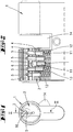
- die Frontalansicht auf einen Schließzylinder,
- Fig. 2
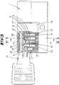
- einen Schnitt gemäß der Linie II-II durch einen mit Stiftzuhaltungen bestückten, in einer Kernbohrung einliegenden Zylinderkern bei nicht eingestecktem Schlüssel,
- Fig. 3
- eine Darstellung gemäß
Figur 2 mit eingestecktem Schlagschlüssel, - Fig. 4
- eine vergrößerte Darstellung gemäß Ausschnitt IV in
Figur 3 , - Fig. 5
- einen Schnitt gemäß der Linie V-V in
Figur 3 , - Fig. 6
- einen Schnitt gemäß der Linie VI-VI in
Figur 3 , - Fig. 7
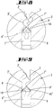
- eine schematische Darstellung zur Beschreibung des Verfahrens zur Ermittlung der Bohrtiefe B,
- Fig. 8
- eine stark vergrößerte Darstellung ähnlich
Figur 7 bei einem andersprofilierten Schlüsselkanal, - Fig. 9
- eine Darstellung gemäß
Figur 8 bei einem noch anders profilierten Schlüsselkanal, - Fig. 10
- eine Darstellung gemäß
Figur 8 bei einem weiter anders profilierten Schlüsselkanal, - Fig. 11
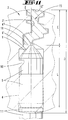
- eine stark vergrößerte Darstellung der
Figur 5 . - Der in den Zeichnungen dargestellte Schließzylinder besitzt ein Schließzylindergehäuse 1, welches zwei zueinander fluchtende Kernbohrungen aufweist. Zwischen den beiden Kernbohrungen liegt in einem Einschnitt ein Schließglied 14. Dieses Schließglied 14 ist mittels einer nicht dargestellten Kupplung mit einem der beiden den Kernbohrungen einsteckenden Zylinders 2 drehgekuppelt, sofern der passende Schlüssel in den Schlüsselkanal 3 des Zylinderkernes 2 eingesteckt ist. Die Kupplung kann mit der Schlüsselspitze erfolgen.
- Der Zylinderkern 2 weist in den Zeichnungen insgesamt vier im Wesentlichen in Radialrichtung zu seiner Drehachse sich erstreckende Kernbohrungen 4 mit einer maximal tiefen Bohrungstiefe auf. Es können auch mehr als vier derartige Kernbohrungen 4 vorgesehen sein. Zusätzlich zu diesen normal tief gebohrten Kernbohrungen 4 ist zumindest eine Kernstiftbohrung 6 vorgesehen, deren Tiefe verkürzt ist.
- In dieser Kernstiftbohrung liegt ein entsprechend kürzerer Kernstift 7. In den dazu benachbarten normal tief eingeschnittenen Kernstiftbohrungen 4 liegt jeweils ein Kernstift 5 ein. Die Länge der Kernstifte 5, 7 definiert das Schlüsselgeheimnis. Zu jedem Kernstift 5 , 7 gibt es einen korrespondierenden Gehäusestift 11, der in einer Gehäusestiftbohrung 13 einliegt und von einer Stiftfeder 12 in Richtung auf den Zylinderkern 2 beaufschlagt wird. Bei nicht eingestecktem Schlüssel (vgl.
Figur 2 ) kreuzen die Gehäusestifte 13 die Drehfuge zwischen Zylinderkern 2 und Gehäusebohrung. - Nur wenn ein passender Schlüssel eingesteckt ist, was in den Zeichnungen nicht dargestellt ist, liegt die Trennebene zwischen den Kernstiften 5,7 und den zugeordneten Gehäusestiften 11 in der Trennfuge, so dass der Zylinderkern 2 in der Gehäusebohrung gedreht werden kann.
- Die
Figur 3 zeigt einen in den Schlüsselkanal 3 eingesteckten Schlagschlüssel 15. Die Kerbeinschnitte 16 haben dort das tiefste Niveau. In denFiguren 4 und11 ist mit dem Buchstaben E die Einschnitttiefe als das Abstandsmaß zwischen Scheitel des Kerbeinschnittes 16 und Schlüsselrücken 15' des Schlagschlüssels bezeichnet. Die Firstlinien 17 der Schrägflanken benachbarter Kerbeinschnitte 16 ragen minimal weit in den Schlüsselkanal in Richtung auf die Mündung 6"' der Kernbohrungen 4, 6. In derFigur 4 ist mit dem Buchstaben T der Abstand zwischen der Firstlinie 17 zweier benachbarter Flanken vom Schlüsselrücken 15 bezeichnet. Aus derFigur 1 ist zu entnehmen, dass die Spitze 7" des in der verkürzten Kernbohrung 6 einliegenden Kernstiftes 7 sich an einer Profilrippe 10 abstützt. Die Spitze 6" hat, wie in derFigur 4 dargestellt, einen Abstand A zur Firstlinie 17 des Schlagschlüssels 15. Wird auf den gemäßFigur 3 im Schlüsselkanal 3 steckenden Schlagschlüssel ein Schlag ausgeübt, so wird über die Schrägflächenanlage der Schrägflanken der Kerbeinschnitte 16 ein Impuls auf die Spitzen der Kernstifte 5 übertragen, was zur Folge hat, dass sich die Gehäusestifte 11 von den Kernstiften entfernen und dabei vollständig in die ihnen zugeordneten Gehäusestiftbohrungen 13 eingetrieben werden. Wegen des Abstandes A wird kein Impuls auf den Kernstift 7 übertragen. DieFigur 7 zeigt in vergrößerter Darstellung die Anlage der Kernstiftspitzen 7" an einer Profilrippe 10. Bei dieser Konstellation entspricht die Bohrtiefe nicht der Eindringtiefe des Kernstiftes 7 in die Kernstiftbohrung 6. - Üblicherweise weichen Spitzenwinkel von Kernstift 7 und Bohrer voneinander ab. Der Winkel α der Kernstiftspitze, also der Winkel, in dem sich die Konturlinien der Kopfquerschnittskontur 9 des Kernstiftes 7 in der Kernstiftspitze 7" treffen, ist in der Regel kleiner als der Winkel β der Kopfquerschnittskontur 9 der Bohrung. Der Winkel α kann im Bereich zwischen 90° und 110° liegen. Der Winkel β beträgt üblicherweise 120°. Liegt also die konstruierte Kernspitze 7" im Freiraum des Schlüsselkanales 3, so stützt sich der Kernstift 7 nicht mit seiner Spitze 7" am Material, beispielsweise an einer Rippe 10 ab. Der Spitzenbereich des Kernstiftes 7 stützt sich vielmehr im Flankenbereich der Spitze, also im Bereich der Flankenlinie 7' an einem Wandungsabschnitt 3' des Schlüsselkanals 3 ab. Wenn ein Bohrer verwendet wird, dessen Kopfquerschnittskontur 8 einen größeren Öffnungswinkel β aufweist, als der Öffnungswinkel α der Kopfquerschnittskontur 9 des Kernstiftes 7, führt dies bei einer derartigen Konstellation dazu, dass die Lage der Spitze 7" des Kernstiftes 7, wie in der Figur 7 dargestellt ist, tiefer in der Kernstiftbohrung 6 liegt als die Spitze 6", die die Bohrtiefe B bestimmt.
- Es besteht also das Problem, die Bohrtiefe B so vorherzusagen, dass der in der Kernbohrung 6 einliegende Kernstift 7 mit seiner Spitze 7" den gewünschten Abstand S zur Mündung 6"' der verkürzten Kernbohrung 6 besitzt.
- Um die Bohrtiefe B zu ermitteln wird ein auf einer grafischen Projektion beruhendes Verfahrens verwendet, welches bevorzugt in einer elektronischen Datenverarbeitungsanlage durchgeführt wird. Zunächst wird die Kopfquerschnittskontur 9 des Kernstiftes 7 derart in einer durch die Zentrumslinie Z der Kernbohrung 6 gelegten Querschnittsebene des Schlüsselkanals 3 projeziert, dass die Spitze 7" den gewünschten Abstand S zur Mündung 6' der Kernbohrung 6 hat. Dieser Abstand kann für Schließzylinderkerne 2 einer bestimmten Serie gleich sein. Die Schlüsselkanäle 3 der Schließzylinderkerne 2 einer Serie und insbesondere einer Schließanlage unterscheiden sich aber hinsichtlich ihrer Rippenstruktur, da die Profilrippen 10 zur Variation des Schließgeheimnisses verwendet werden. In einen Schlüsselkanal 3 können nur solche Schlüssel eingesteckt werden, die an der Stelle, wo der Schlüsselkanal 3 eine Profilrippe 10 aufweist, eine entsprechende Nut aufweist. Da Schlüsselkanäle 3 von verschiedenen Schließzylindern einer Schließanlage eine verschiedene Profilrippenanordnung besitzen, ist nicht sichergestellt, dass die Spitze 6" der Kernbohrung 6 im Bereich einer Rippe liegt. Die Abstützung des Kernstiftes 7 erfolgt somit in der Regel an irgendeinem Punkt P auf der kegelförmigen oder gerundeten Spitzenkontur des Kernstiftes 7. Um diesen Punkt aufzufinden, wird die Kopfquerschnittskontur 9 des Kernstiftes 7 in der oben beschriebenen Weise in die Querschnittsebene des Schlüsselkanales 3 projiziert. Anschließend wird ein Schnitt- oder Berührungspunkt P gesucht, an dem die Konturlinie 9' des Kopfquerschnitts 9 des Kernstückes 7 die Konturlinie 3' des Querschnitts des Schlüsselkanals 3 schneidet oder berührt. Dabei wird der der Spitze 7" des Kernstiftes 7 nächstgelegene Schnitt- oder Berührungspunkt P gesucht.
- In einem darauffolgenden Schritt wird die Kopfquerschnittskontur 8 des derart in die Querschnittsebene projiziert, dass die Spitze 6" in der Zentrumslinie Z der Kernbohrung 6 liegt. Die Punkte 6" und 7" liegen somit auf derselben Zentrumslinie Z. Da der Punkt P durch den vorangegangenen Konstruktionsschritt festliegt, muss jetzt die axiale Lage des Spitzenpunktes 6" der Kopfquerschnittskontur 8 des Bohrers entlang der Zentrumslinie Z soweit verschoben werden, dass die Konturlinie 8' der Kopfquerschnittskontur 8 des Bohrers ebenfalls durch den Punkt P verläuft. Der Punkt P ist dann der Abstützpunkt, an dem sich die kegelmantelförmige Spitzenstruktur oder die gerundete Spitzenkontur des Kernstiftes 7 an einem Vorsprung des Schlüsselkanals 3, insbesondere also einem Wandabschnitt 3' des Schlüsselkanals oder einem Abschnitt einer Profilrippe 10 abstützt. Hierdurch ist die Bohrtiefe B ermittelt worden.
- Die
Figuren 8 bis 10 zeigen, dass das Verfahren an unterschiedlich profilierten Schlüsselkanälen 3 anwendbar ist, wobei jedes Mal die Lage des Spitzenpunktes 7" des Kernstiftes von der Lage des Spitzenpunktes 6" der Bohrung bzw. der Eindringtiefe B des Bohrers abweicht. Bei dem inFigur 8 dargestellten Ausführungsbeispiels stützt sich ein Abschnitt des kegelförmigen Spitzenbereich des Kernstiftes 7 an einer Profilrippe 10 ab. - Bei dem in der
Figur 9 dargestellten Ausführungsbeispiel befindet sich auf der linken Seite des Schlüsselkanales 3 ein erster Abstützpunkt P und auf der rechten Seite des Schlüsselkanales 3 ein zweiter Abstützpunkt P'. Auch hier liegt der Spitzenpunkt 6" der Bohrung im Freiraum des Schlüsselkanales 3. - Auch bei dem in der
Figur 10 dargestellten Beispiel gibt es in der Querschnittsebene des Zylinderkernes 2 zwei Abstützpunkte, P, P', die jeweils einer Seite des 3' des Schlüsselkanales 3 zugeordnet sind. - Der Durchmesser D des Zylinderkernes 2 ist in der
Figur 11 mit D bezeichnet. Um eine möglichst große Sicherheit zu gewährleisten, sollte bei der Bestiftung des Schließzylinders folgendes Ungleichungspaar berücksichtigt werden: S < D - T oder L >= D - E, wobei L das Längenmaß eines normalen Kernstiftes 5 ist, wie er in derFigur 11 dargestellt ist. Solange die erste Ungleichung erfüllt ist, ist sichergestellt, dass die Firstlinie 17 einen Abstand A zur Spitze 7" des Kernstiftes 7 besitzt. Dieser, in einer verkürzten Kernbohrung 6 steckende Kernstift 7 wird somit von einem Schlagschlüssel, bei dem die Firstlinien 17 um das Maß T vom Rücken 15' entfernt sind, nicht berührt. Der zum Kernstift 7 gehörende Gehäusestift kann also bei einer Schlagschlüsselöffnungsmethode mit einem derartigen Schlagschlüssel 15 nicht bewegt werden. Die zweite Ungleichung sollte für den Fall erfüllt sein, bei dem der Abstand T von Firstlinie 17 zu Schlüsselrücken 15' so groß ist, dass ein Abstand A nicht vorhanden ist, also ein derartiger Schlagschlüssel 15 einen Impuls auf den Kernstift 7 übertragen kann. Durch die zweite Ungleichung ist sichergestellt, dass bereits eine geringe Verlagerung des normalen Kernstiftes 5 mit der Länge L zu einem Eintritt dieses Kernstiftes 5 in die Gehäusebohrung führt, so dass hier eine Sperrwirkung eintritt. - Dem Verfahren zur Bestimmung der Bohrtiefe B für die verkürzte Kernbohrung 6 geht eine Bestimmung der Lage der Spitze 7" des Kernstiftes voraus, also eine Bestimmung des Maßes S, aus der dann mittels des zuvor beschriebenen Verfahrens die Bohrtiefe B ermittelt wird. Das Maß S muss so gewählt sein, dass die um das Maß T vom Schlüsselrücken 15' beabstandete Firstlinie 17 einen Abstand A von der Spitze 7" besitzt. Ist dies nicht mehr der Fall, muss die Summe aus dem Abstand des Kerbscheitels zum Schlüsselrücken 15', also das Maß E mit dem Maß der Länge L des in dieser Kernbohrung einsteckenden Kernstiftes 5 größer sein als der Durchmesser D des Zylinderkernes 2.
- Zylinderkerne werden mit unterschiedlich langen Kernstiften bestückt, da die Länge der Kernstifte und deren Anordnung das Schlüsselgeheimnis bestimmen. In einer Weiterbildung des Verfahrens ist deshalb vorgesehen, dass zunächst die Länge L des längsten Kernstiftes und die Länge des kürzesten Kernstiftes bestimmt wird. Die verkürzte Kernbohrung wird dann dem kürzesten Kernstift zugeordnet und das Maß S, welches den gewünschten Abstand der Spitze 7" des Kernstiftes 7 zur Mündung 6"' der Kernbohrung 6 bedeutet, nach folgender Formel bestimmt: S <= L + E- T und anschließend die Kernbohrungen 4,6 gebohrt werden, wobei die dem kürzesten Kenstift 7 zugeordnete Bohrung 6 eine Bohrtiefe B erhält, die insbesondere nach Anspruch 1 vom gewünschten Abstand S abgeleitet ist.
- S sollte dabei bevorzugt mindestens um das Maß eines Stufensprunges, also 0,5 mm kleiner sein als L + E - T, damit bei einem entsprechend niedrig eingeschnittenen Schlagschlüssel der längste normale Kernstift mit zumindest 0,5 mm die Trennebene kreuzt. Die Differenz T - E, die dem auf die Zentrumslinie projizierten Abstand der Kerbscheitel 16 von den Firstlinien 17 entspricht, lässt sich mit Hilfe der nachfolgenden Formel berechnen:

- Mit C ist hier der in Erstreckungsrichtung gemessene Abstand zweier benachbarter Kernscheitel bezeichnet. Dieser Abstand entspricht der Distanz zweier benachbarter Kernbohrungen. Mit dem Winkel γ ist der Flankenwinkel der beiden Kerbflanken bezeichnet, die sich in einem Scheitel 16 treffen (vergleiche
Figur 4 ). Dieser Winkel beträgt zwischen 90° und 120°. Insofern lässt sich durch die Vorgabe eines minimalen Wertes für den Winkel γ der maximal mögliche Wert des Abstandes T - E ermitteln, ohne dass man den Schlagschlüssel kennen muss.
Claims (7)
- Verfahren zur Bestimmung der Bohrtiefe (B) für eine verkürzte Kernbohrung (6), die in einen Zylinderkern (2) eines Schließzylinders einzubringen ist, wobei der fertige Zylinderkern (2) einen gegebenenfalls eine Profilrippe (19) ausbildenden Schlüsselkanal (3) aufweist und in der verkürzten Kernbohrung (6) ein eine Spitze (7") mit einer sich daran anschließenden, insbesondere kegelförmigen oder gerundeten Kopffläche (7) aufweisender Kernstift (7) einliegt, wobei bei einem nicht in den Schlüsselkanal (3) eingesteckten passenden Schlüssel oder bei einem in den Schlüsselkanal (3) eingesteckten Schlagschlüssel (15) die Spitze (7") des Kernstiftes (7) als Folge einer Anlage der Kopffläche (7') an zumindest einem Anlagepunkt (P) der Wandung (3') des Schlüsselkanales (3) einen Abstand (S) zur Mündung (6"') der verkürzten Kernbohrung (6) aufweist, dadurch gekennzeichnet, dass ein Bohrer verwendet wird, dessen Kopfquerschnittskontur (8) einen größeren Öffnungswinkel (β) aufweist, als der Öffnungswinkel (α) der Kopfquerschnittskontur (9) des Kernstiftes (7), und durch folgende Schritte:- Projizieren der Kopfquerschnittskontur (9) des Kernstiftes (7) derart in eine durch die Zentrumslinie (Z) der Kernbohrung (6) gelegten Querschnittsebene des Schlüsselkanals (3), dass die Spitze (7") der Projektion des Kernstiftes (7) den gewünschten Abstand (S) zur Mündung (6"') der Kernbohrung (6) hat;- Auffinden des der Spitze (7") der Projektion des Kernstiftes (7) nächstgelegenen Schnitt- oder Berührungspunktes (P) der Konturlinie (9') des Kopfquerschnitts (9) des Kernstiftes (7) mit der Konturlinie (3') des Querschnitts des Schlüsselkanals (3);- Projizieren der Kopfquerschnittskontur (8) des Bohrers derart in die Querschnittsebene, dass deren Spitze (6") in der Zentrumslinie (Z) liegt und deren Konturlinie (8') durch den Punkt (P) verläuft.
- Verfahren zum Bohren einer verkürzten Kernbohrung (6) in den Zylinderkern (2) eines Schließzylinders, gekennzeichnet durch eine Bestimmung der Bohrtiefe (B) gemäß Anspruch 1 und anschließendem Bohren der Kernbohrung (6).
- Verfahren nach Anspruch 2, dadurch gekennzeichnet, dass, nach dem der Zylinderkern (2) insbesondere durch eine spanende Bearbeitung in Form gebracht worden ist, zunächst eine Mehrzahl von im Wesentlichen radial sich zum Drehzentrum des Zylinderkernes (2) sich erstreckende Kernbohrungen (6, 4) eingebracht werden, wobei zumindest eine verkürzte Bohrung gemäß Anspruch 2 gefertigt ist und anschließend der Schlüsselkanal (3) insbesondere durch Räumen gefertigt wird.
- Verfahren nach Anspruch 2, dadurch gekennzeichnet, dass vor dem Bohren der Kernbohrungen (6,4) der Schlüsselkanal (3) insbesondere durch Räumen gefertigt wird.
- Verfahren nach einem der vorhergehenden Ansprüche, dadurch gekennzeichnet, dass die Tiefe (B) der verkürzten Kernbohrung (6) so gewählt ist, dass die Spitze (7") des in der verkürzten Kernbohrung (6) einliegenden Kernstiftes (7) einen Abstand (A) zur Firstlinie (17) zweier Schrägflanken benachbarter Kerbeinschnitten (16) eines im Schlüsselkanal (3) steckenden Schlagschlüssels (15) aufweist.
- Verfahren nach einem der vorhergehenden Ansprüche, dadurch gekennzeichnet, dass entweder der Abstand (S) der Spitze (7") des in der verkürzten Kernbohrung (6) einliegenden Kernstiftes (7) zur Mündung (6"') der Kernbohrung (6) geringer ist, als die Differenz zwischen Durchmesser (D) des Zylinderkernes (2) und des Abstandes (T) einer Flankenfirstlinie (17) vom Schlüsselrücken (15') oder dass die Länge (L) eines anderen Kernstiftes (4) größer ist, als die Differenz des Durchmessers (D) des Zylinderkernes (2) und des Abstandes (E) der Scheitellinie (16) der zugeordneten Kerbaussparung zum Schlüsselrücken (15') eines Schlagschlüssels (15).
- Verfahren zum Bohren der Kernbohrungen (4, 6) in einen Zylinderkern (2) eines Schließzylinders, wobei zunächst die Länge (L) des längsten Kernstiftes (5) und die Position des kürzesten Kernstiftes (7) bestimmt werden, der gewünschte Abstand (S) der Spitze (7") des kürzesten Kernstiftes (7) nach folgender Formel bestimmt wird: S <= L + E - T, wobei (T - E) der auf die Zentrumslinie (Z) der Kernbohrung (6) projizierte Abstand der Scheitellinien (16) der Kerbflanken von den Firstlinien (17) der Kerbflanken zweier benachbarter Einschnitte eines Schlagschlüssels (15) ist, dessen Kerbeinschnittscheitellinien (16) im Wesentlichen auf einem gemeinsamen Niveau liegen, und gemäß der Formel T - E = C/ (2 * tan (γ/2)) bestimmbar ist, wobei C der Abstand zweier benachbarter Kernbohrungen ist und γ zwischen 90 und 120° liegt, und anschließend die Kernbohrungen (4,6) gebohrt werden, wobei die dem kürzesten Kernstift (7) zugeordnete Bohrung (6) bis eine Bohrtiefe (B) erfolgt, die unter Berücksichtigung der Verschiedenheit der Kopfquerschnittskontur (9) des Kernstiftes (7) von der Kopfquerschnittskontur (8) des Bohrers nach dem Verfahren gemäß Anspruch 1 ermittelt wird.
Priority Applications (1)
| Application Number | Priority Date | Filing Date | Title |
|---|---|---|---|
| PL08172317T PL2075394T3 (pl) | 2007-12-31 | 2008-12-19 | Sposób wyznaczania głębokości skróconego otworu rdzeniowego w rdzeniu wkładki zamkowej |
Applications Claiming Priority (1)
| Application Number | Priority Date | Filing Date | Title |
|---|---|---|---|
| DE200710063237 DE102007063237A1 (de) | 2007-12-31 | 2007-12-31 | Verfahren zur Herstellung eines Schließzylinders |
Publications (2)
| Publication Number | Publication Date |
|---|---|
| EP2075394A1 EP2075394A1 (de) | 2009-07-01 |
| EP2075394B1 true EP2075394B1 (de) | 2018-03-14 |
Family
ID=40627133
Family Applications (1)
| Application Number | Title | Priority Date | Filing Date |
|---|---|---|---|
| EP08172317.3A Not-in-force EP2075394B1 (de) | 2007-12-31 | 2008-12-19 | Verfahren zur Bestimmung der Bohrtiefe einer Kernbohrung |
Country Status (4)
| Country | Link |
|---|---|
| EP (1) | EP2075394B1 (de) |
| DE (1) | DE102007063237A1 (de) |
| ES (1) | ES2666652T3 (de) |
| PL (1) | PL2075394T3 (de) |
Families Citing this family (1)
| Publication number | Priority date | Publication date | Assignee | Title |
|---|---|---|---|---|
| CN111287584B (zh) * | 2020-03-31 | 2024-09-24 | 湖南金正科技有限公司 | 一种双匙联动的保管箱锁及锁芯片的设计方法 |
Family Cites Families (4)
| Publication number | Priority date | Publication date | Assignee | Title |
|---|---|---|---|---|
| DE19541325A1 (de) | 1995-11-06 | 1997-05-07 | Winkhaus Fa August | Schließzylinder |
| DE102004045792A1 (de) | 2004-09-22 | 2006-04-06 | Dom Sicherheitstechnik Gmbh & Co. Kg | Schliesszylinder |
| ES2273566B1 (es) | 2005-03-30 | 2008-03-01 | Talleres De Escoriaza, S.A. | Dispositivo de seguridad para cilindros de cerraduras. |
| DE102007019714A1 (de) | 2007-04-25 | 2008-10-30 | C. Ed. Schulte Gmbh Zylinderschlossfabrik | Schließzylinder mit einem eine Sollbruch-/Biegestelle aufweisenden Kernstift |
-
2007
- 2007-12-31 DE DE200710063237 patent/DE102007063237A1/de not_active Withdrawn
-
2008
- 2008-12-19 EP EP08172317.3A patent/EP2075394B1/de not_active Not-in-force
- 2008-12-19 ES ES08172317.3T patent/ES2666652T3/es active Active
- 2008-12-19 PL PL08172317T patent/PL2075394T3/pl unknown
Non-Patent Citations (1)
| Title |
|---|
| None * |
Also Published As
| Publication number | Publication date |
|---|---|
| DE102007063237A1 (de) | 2009-07-02 |
| PL2075394T3 (pl) | 2018-08-31 |
| EP2075394A1 (de) | 2009-07-01 |
| ES2666652T3 (es) | 2018-05-07 |
Similar Documents
| Publication | Publication Date | Title |
|---|---|---|
| EP2390030B1 (de) | Verfahren zum Profilieren eines Flachschlüssels sowie nach dem Verfahren gefertigter Flachschlüssel | |
| WO2003011508A2 (de) | Gewindeformer oder -bohrer | |
| DE102011086491B4 (de) | Schraube | |
| DE3833040A1 (de) | Bohrhilfevorrichtung | |
| DE102004021580B3 (de) | Aus Schlüssel und Schließzylinder bestehende Schließvorrichtung | |
| EP4148212A1 (de) | Schlüssel, schliesssystem, schliesszylinder und herstellungsverfahren | |
| DE2643263A1 (de) | Schluessel fuer ein zylinderschloss und verfahren zu seiner herstellung | |
| EP3656494B1 (de) | Stufenbohrer | |
| CH717636B1 (de) | Schlüssel, Kombination aus Schlüssel und Schliesszylinder. | |
| EP2360334B1 (de) | Schließzylinder | |
| EP1333136B1 (de) | Schliesszylinder | |
| AT508869B1 (de) | Schlüssel und zylinderschloss | |
| DE102004045792A1 (de) | Schliesszylinder | |
| EP2075394A1 (de) | Verfahren zur Herstellung eines Schließzylinders | |
| WO2013030077A1 (de) | Drehschliesszylinder und sicherheitsschlüssel | |
| AT521007B1 (de) | Stiftzylinder-schlüssel-system und schlüssel dafür | |
| EP2145066A1 (de) | Schliesszylinder mit einem eine sollbruch-/biegestelle aufweisenden kernstift | |
| EP1333135B1 (de) | Schliesszylinder | |
| EP2848338B1 (de) | Bohrkopfeinsatz oder Bohrkopfaufsatz sowie Bohrer | |
| DE102004011637B4 (de) | Schließzylinder | |
| EP1464778B1 (de) | Schliesszylinder | |
| DE10219901B4 (de) | Schließzylinder mit dem Steg zwischen zwei Gehäusehälften zugeordneter Sollbiegestelle | |
| AT502151B1 (de) | Zylinderschloss mit nachsperrsicherung | |
| DE19732450B4 (de) | Wendeschlüssel-Schließzylinder | |
| EP3428371A1 (de) | Schliesskern, schliesszylinder, schlüssel, schliessvorrichtung und zylinderschloss sowie verfahren hierzu |
Legal Events
| Date | Code | Title | Description |
|---|---|---|---|
| PUAI | Public reference made under article 153(3) epc to a published international application that has entered the european phase |
Free format text: ORIGINAL CODE: 0009012 |
|
| AK | Designated contracting states |
Kind code of ref document: A1 Designated state(s): AT BE BG CH CY CZ DE DK EE ES FI FR GB GR HR HU IE IS IT LI LT LU LV MC MT NL NO PL PT RO SE SI SK TR |
|
| AX | Request for extension of the european patent |
Extension state: AL BA MK RS |
|
| 17P | Request for examination filed |
Effective date: 20090915 |
|
| AKX | Designation fees paid |
Designated state(s): AT BE BG CH CY CZ DE DK EE ES FI FR GB GR HR HU IE IS IT LI LT LU LV MC MT NL NO PL PT RO SE SI SK TR |
|
| 17Q | First examination report despatched |
Effective date: 20170308 |
|
| GRAP | Despatch of communication of intention to grant a patent |
Free format text: ORIGINAL CODE: EPIDOSNIGR1 |
|
| INTG | Intention to grant announced |
Effective date: 20170606 |
|
| GRAJ | Information related to disapproval of communication of intention to grant by the applicant or resumption of examination proceedings by the epo deleted |
Free format text: ORIGINAL CODE: EPIDOSDIGR1 |
|
| GRAP | Despatch of communication of intention to grant a patent |
Free format text: ORIGINAL CODE: EPIDOSNIGR1 |
|
| INTC | Intention to grant announced (deleted) | ||
| INTG | Intention to grant announced |
Effective date: 20171106 |
|
| GRAS | Grant fee paid |
Free format text: ORIGINAL CODE: EPIDOSNIGR3 |
|
| GRAA | (expected) grant |
Free format text: ORIGINAL CODE: 0009210 |
|
| AK | Designated contracting states |
Kind code of ref document: B1 Designated state(s): AT BE BG CH CY CZ DE DK EE ES FI FR GB GR HR HU IE IS IT LI LT LU LV MC MT NL NO PL PT RO SE SI SK TR |
|
| REG | Reference to a national code |
Ref country code: GB Ref legal event code: FG4D Free format text: NOT ENGLISH |
|
| REG | Reference to a national code |
Ref country code: CH Ref legal event code: EP Ref country code: AT Ref legal event code: REF Ref document number: 979045 Country of ref document: AT Kind code of ref document: T Effective date: 20180315 |
|
| REG | Reference to a national code |
Ref country code: IE Ref legal event code: FG4D Free format text: LANGUAGE OF EP DOCUMENT: GERMAN |
|
| REG | Reference to a national code |
Ref country code: DE Ref legal event code: R096 Ref document number: 502008015951 Country of ref document: DE |
|
| REG | Reference to a national code |
Ref country code: CH Ref legal event code: NV Representative=s name: R. A. EGLI AND CO. PATENTANWAELTE, CH |
|
| REG | Reference to a national code |
Ref country code: ES Ref legal event code: FG2A Ref document number: 2666652 Country of ref document: ES Kind code of ref document: T3 Effective date: 20180507 |
|
| REG | Reference to a national code |
Ref country code: NL Ref legal event code: FP |
|
| REG | Reference to a national code |
Ref country code: LT Ref legal event code: MG4D |
|
| PG25 | Lapsed in a contracting state [announced via postgrant information from national office to epo] |
Ref country code: LT Free format text: LAPSE BECAUSE OF FAILURE TO SUBMIT A TRANSLATION OF THE DESCRIPTION OR TO PAY THE FEE WITHIN THE PRESCRIBED TIME-LIMIT Effective date: 20180314 Ref country code: NO Free format text: LAPSE BECAUSE OF FAILURE TO SUBMIT A TRANSLATION OF THE DESCRIPTION OR TO PAY THE FEE WITHIN THE PRESCRIBED TIME-LIMIT Effective date: 20180614 Ref country code: HR Free format text: LAPSE BECAUSE OF FAILURE TO SUBMIT A TRANSLATION OF THE DESCRIPTION OR TO PAY THE FEE WITHIN THE PRESCRIBED TIME-LIMIT Effective date: 20180314 Ref country code: FI Free format text: LAPSE BECAUSE OF FAILURE TO SUBMIT A TRANSLATION OF THE DESCRIPTION OR TO PAY THE FEE WITHIN THE PRESCRIBED TIME-LIMIT Effective date: 20180314 Ref country code: CY Free format text: LAPSE BECAUSE OF FAILURE TO SUBMIT A TRANSLATION OF THE DESCRIPTION OR TO PAY THE FEE WITHIN THE PRESCRIBED TIME-LIMIT Effective date: 20180314 |
|
| PG25 | Lapsed in a contracting state [announced via postgrant information from national office to epo] |
Ref country code: LV Free format text: LAPSE BECAUSE OF FAILURE TO SUBMIT A TRANSLATION OF THE DESCRIPTION OR TO PAY THE FEE WITHIN THE PRESCRIBED TIME-LIMIT Effective date: 20180314 Ref country code: SE Free format text: LAPSE BECAUSE OF FAILURE TO SUBMIT A TRANSLATION OF THE DESCRIPTION OR TO PAY THE FEE WITHIN THE PRESCRIBED TIME-LIMIT Effective date: 20180314 Ref country code: GR Free format text: LAPSE BECAUSE OF FAILURE TO SUBMIT A TRANSLATION OF THE DESCRIPTION OR TO PAY THE FEE WITHIN THE PRESCRIBED TIME-LIMIT Effective date: 20180615 Ref country code: BG Free format text: LAPSE BECAUSE OF FAILURE TO SUBMIT A TRANSLATION OF THE DESCRIPTION OR TO PAY THE FEE WITHIN THE PRESCRIBED TIME-LIMIT Effective date: 20180614 |
|
| PG25 | Lapsed in a contracting state [announced via postgrant information from national office to epo] |
Ref country code: MT Free format text: LAPSE BECAUSE OF FAILURE TO SUBMIT A TRANSLATION OF THE DESCRIPTION OR TO PAY THE FEE WITHIN THE PRESCRIBED TIME-LIMIT Effective date: 20180314 |
|
| REG | Reference to a national code |
Ref country code: SK Ref legal event code: T3 Ref document number: E 27558 Country of ref document: SK |
|
| PG25 | Lapsed in a contracting state [announced via postgrant information from national office to epo] |
Ref country code: EE Free format text: LAPSE BECAUSE OF FAILURE TO SUBMIT A TRANSLATION OF THE DESCRIPTION OR TO PAY THE FEE WITHIN THE PRESCRIBED TIME-LIMIT Effective date: 20180314 |
|
| REG | Reference to a national code |
Ref country code: RO Ref legal event code: EPE |
|
| REG | Reference to a national code |
Ref country code: DE Ref legal event code: R097 Ref document number: 502008015951 Country of ref document: DE |
|
| PG25 | Lapsed in a contracting state [announced via postgrant information from national office to epo] |
Ref country code: PT Free format text: LAPSE BECAUSE OF FAILURE TO SUBMIT A TRANSLATION OF THE DESCRIPTION OR TO PAY THE FEE WITHIN THE PRESCRIBED TIME-LIMIT Effective date: 20180716 |
|
| PLBE | No opposition filed within time limit |
Free format text: ORIGINAL CODE: 0009261 |
|
| STAA | Information on the status of an ep patent application or granted ep patent |
Free format text: STATUS: NO OPPOSITION FILED WITHIN TIME LIMIT |
|
| PG25 | Lapsed in a contracting state [announced via postgrant information from national office to epo] |
Ref country code: DK Free format text: LAPSE BECAUSE OF FAILURE TO SUBMIT A TRANSLATION OF THE DESCRIPTION OR TO PAY THE FEE WITHIN THE PRESCRIBED TIME-LIMIT Effective date: 20180314 |
|
| 26N | No opposition filed |
Effective date: 20181217 |
|
| PG25 | Lapsed in a contracting state [announced via postgrant information from national office to epo] |
Ref country code: SI Free format text: LAPSE BECAUSE OF FAILURE TO SUBMIT A TRANSLATION OF THE DESCRIPTION OR TO PAY THE FEE WITHIN THE PRESCRIBED TIME-LIMIT Effective date: 20180314 |
|
| REG | Reference to a national code |
Ref country code: DE Ref legal event code: R119 Ref document number: 502008015951 Country of ref document: DE |
|
| PG25 | Lapsed in a contracting state [announced via postgrant information from national office to epo] |
Ref country code: CZ Free format text: LAPSE BECAUSE OF NON-PAYMENT OF DUE FEES Effective date: 20181219 |
|
| REG | Reference to a national code |
Ref country code: CH Ref legal event code: PL |
|
| REG | Reference to a national code |
Ref country code: NL Ref legal event code: MM Effective date: 20190101 |
|
| GBPC | Gb: european patent ceased through non-payment of renewal fee |
Effective date: 20181219 |
|
| PG25 | Lapsed in a contracting state [announced via postgrant information from national office to epo] |
Ref country code: MC Free format text: LAPSE BECAUSE OF FAILURE TO SUBMIT A TRANSLATION OF THE DESCRIPTION OR TO PAY THE FEE WITHIN THE PRESCRIBED TIME-LIMIT Effective date: 20180314 Ref country code: LU Free format text: LAPSE BECAUSE OF NON-PAYMENT OF DUE FEES Effective date: 20181219 Ref country code: RO Free format text: LAPSE BECAUSE OF NON-PAYMENT OF DUE FEES Effective date: 20180314 |
|
| REG | Reference to a national code |
Ref country code: SK Ref legal event code: MM4A Ref document number: E 27558 Country of ref document: SK Effective date: 20181219 |
|
| REG | Reference to a national code |
Ref country code: IE Ref legal event code: MM4A |
|
| PG25 | Lapsed in a contracting state [announced via postgrant information from national office to epo] |
Ref country code: NL Free format text: LAPSE BECAUSE OF NON-PAYMENT OF DUE FEES Effective date: 20190101 |
|
| REG | Reference to a national code |
Ref country code: BE Ref legal event code: MM Effective date: 20181231 |
|
| PG25 | Lapsed in a contracting state [announced via postgrant information from national office to epo] |
Ref country code: DE Free format text: LAPSE BECAUSE OF NON-PAYMENT OF DUE FEES Effective date: 20190702 Ref country code: FR Free format text: LAPSE BECAUSE OF NON-PAYMENT OF DUE FEES Effective date: 20181231 Ref country code: IT Free format text: LAPSE BECAUSE OF NON-PAYMENT OF DUE FEES Effective date: 20181219 Ref country code: SK Free format text: LAPSE BECAUSE OF NON-PAYMENT OF DUE FEES Effective date: 20181219 Ref country code: IE Free format text: LAPSE BECAUSE OF NON-PAYMENT OF DUE FEES Effective date: 20181219 |
|
| PG25 | Lapsed in a contracting state [announced via postgrant information from national office to epo] |
Ref country code: BE Free format text: LAPSE BECAUSE OF NON-PAYMENT OF DUE FEES Effective date: 20181231 |
|
| PG25 | Lapsed in a contracting state [announced via postgrant information from national office to epo] |
Ref country code: CH Free format text: LAPSE BECAUSE OF NON-PAYMENT OF DUE FEES Effective date: 20181231 Ref country code: LI Free format text: LAPSE BECAUSE OF NON-PAYMENT OF DUE FEES Effective date: 20181231 Ref country code: GB Free format text: LAPSE BECAUSE OF NON-PAYMENT OF DUE FEES Effective date: 20181219 |
|
| REG | Reference to a national code |
Ref country code: ES Ref legal event code: FD2A Effective date: 20200204 |
|
| REG | Reference to a national code |
Ref country code: AT Ref legal event code: MM01 Ref document number: 979045 Country of ref document: AT Kind code of ref document: T Effective date: 20181219 |
|
| PG25 | Lapsed in a contracting state [announced via postgrant information from national office to epo] |
Ref country code: AT Free format text: LAPSE BECAUSE OF NON-PAYMENT OF DUE FEES Effective date: 20181219 Ref country code: ES Free format text: LAPSE BECAUSE OF NON-PAYMENT OF DUE FEES Effective date: 20181220 |
|
| PG25 | Lapsed in a contracting state [announced via postgrant information from national office to epo] |
Ref country code: HU Free format text: LAPSE BECAUSE OF FAILURE TO SUBMIT A TRANSLATION OF THE DESCRIPTION OR TO PAY THE FEE WITHIN THE PRESCRIBED TIME-LIMIT; INVALID AB INITIO Effective date: 20081219 |
|
| PG25 | Lapsed in a contracting state [announced via postgrant information from national office to epo] |
Ref country code: IS Free format text: LAPSE BECAUSE OF FAILURE TO SUBMIT A TRANSLATION OF THE DESCRIPTION OR TO PAY THE FEE WITHIN THE PRESCRIBED TIME-LIMIT Effective date: 20180714 |
|
| PG25 | Lapsed in a contracting state [announced via postgrant information from national office to epo] |
Ref country code: PL Free format text: LAPSE BECAUSE OF NON-PAYMENT OF DUE FEES Effective date: 20181219 |
|
| PG25 | Lapsed in a contracting state [announced via postgrant information from national office to epo] |
Ref country code: TR Free format text: LAPSE BECAUSE OF NON-PAYMENT OF DUE FEES Effective date: 20181219 |