EP2075312A1 - Process for producing nitride phosphor or oxonitride phosphor - Google Patents
Process for producing nitride phosphor or oxonitride phosphor Download PDFInfo
- Publication number
- EP2075312A1 EP2075312A1 EP07806968A EP07806968A EP2075312A1 EP 2075312 A1 EP2075312 A1 EP 2075312A1 EP 07806968 A EP07806968 A EP 07806968A EP 07806968 A EP07806968 A EP 07806968A EP 2075312 A1 EP2075312 A1 EP 2075312A1
- Authority
- EP
- European Patent Office
- Prior art keywords
- phosphor
- nitride
- firing
- container
- carbon
- Prior art date
- Legal status (The legal status is an assumption and is not a legal conclusion. Google has not performed a legal analysis and makes no representation as to the accuracy of the status listed.)
- Granted
Links
Images

Classifications
-
- C—CHEMISTRY; METALLURGY
- C04—CEMENTS; CONCRETE; ARTIFICIAL STONE; CERAMICS; REFRACTORIES
- C04B—LIME, MAGNESIA; SLAG; CEMENTS; COMPOSITIONS THEREOF, e.g. MORTARS, CONCRETE OR LIKE BUILDING MATERIALS; ARTIFICIAL STONE; CERAMICS; REFRACTORIES; TREATMENT OF NATURAL STONE
- C04B35/00—Shaped ceramic products characterised by their composition; Ceramics compositions; Processing powders of inorganic compounds preparatory to the manufacturing of ceramic products
- C04B35/515—Shaped ceramic products characterised by their composition; Ceramics compositions; Processing powders of inorganic compounds preparatory to the manufacturing of ceramic products based on non-oxide ceramics
- C04B35/58—Shaped ceramic products characterised by their composition; Ceramics compositions; Processing powders of inorganic compounds preparatory to the manufacturing of ceramic products based on non-oxide ceramics based on borides, nitrides, i.e. nitrides, oxynitrides, carbonitrides or oxycarbonitrides or silicides
- C04B35/597—Shaped ceramic products characterised by their composition; Ceramics compositions; Processing powders of inorganic compounds preparatory to the manufacturing of ceramic products based on non-oxide ceramics based on borides, nitrides, i.e. nitrides, oxynitrides, carbonitrides or oxycarbonitrides or silicides based on silicon oxynitride, e.g. SIALONS
-
- C—CHEMISTRY; METALLURGY
- C04—CEMENTS; CONCRETE; ARTIFICIAL STONE; CERAMICS; REFRACTORIES
- C04B—LIME, MAGNESIA; SLAG; CEMENTS; COMPOSITIONS THEREOF, e.g. MORTARS, CONCRETE OR LIKE BUILDING MATERIALS; ARTIFICIAL STONE; CERAMICS; REFRACTORIES; TREATMENT OF NATURAL STONE
- C04B35/00—Shaped ceramic products characterised by their composition; Ceramics compositions; Processing powders of inorganic compounds preparatory to the manufacturing of ceramic products
- C04B35/622—Forming processes; Processing powders of inorganic compounds preparatory to the manufacturing of ceramic products
- C04B35/626—Preparing or treating the powders individually or as batches ; preparing or treating macroscopic reinforcing agents for ceramic products, e.g. fibres; mechanical aspects section B
- C04B35/62605—Treating the starting powders individually or as mixtures
- C04B35/6261—Milling
- C04B35/6262—Milling of calcined, sintered clinker or ceramics
-
- C—CHEMISTRY; METALLURGY
- C09—DYES; PAINTS; POLISHES; NATURAL RESINS; ADHESIVES; COMPOSITIONS NOT OTHERWISE PROVIDED FOR; APPLICATIONS OF MATERIALS NOT OTHERWISE PROVIDED FOR
- C09K—MATERIALS FOR MISCELLANEOUS APPLICATIONS, NOT PROVIDED FOR ELSEWHERE
- C09K11/00—Luminescent materials, e.g. electroluminescent or chemiluminescent
- C09K11/08—Luminescent materials, e.g. electroluminescent or chemiluminescent containing inorganic luminescent materials
- C09K11/0883—Arsenides; Nitrides; Phosphides
-
- C—CHEMISTRY; METALLURGY
- C09—DYES; PAINTS; POLISHES; NATURAL RESINS; ADHESIVES; COMPOSITIONS NOT OTHERWISE PROVIDED FOR; APPLICATIONS OF MATERIALS NOT OTHERWISE PROVIDED FOR
- C09K—MATERIALS FOR MISCELLANEOUS APPLICATIONS, NOT PROVIDED FOR ELSEWHERE
- C09K11/00—Luminescent materials, e.g. electroluminescent or chemiluminescent
- C09K11/08—Luminescent materials, e.g. electroluminescent or chemiluminescent containing inorganic luminescent materials
- C09K11/63—Luminescent materials, e.g. electroluminescent or chemiluminescent containing inorganic luminescent materials containing boron
-
- C—CHEMISTRY; METALLURGY
- C09—DYES; PAINTS; POLISHES; NATURAL RESINS; ADHESIVES; COMPOSITIONS NOT OTHERWISE PROVIDED FOR; APPLICATIONS OF MATERIALS NOT OTHERWISE PROVIDED FOR
- C09K—MATERIALS FOR MISCELLANEOUS APPLICATIONS, NOT PROVIDED FOR ELSEWHERE
- C09K11/00—Luminescent materials, e.g. electroluminescent or chemiluminescent
- C09K11/08—Luminescent materials, e.g. electroluminescent or chemiluminescent containing inorganic luminescent materials
- C09K11/64—Luminescent materials, e.g. electroluminescent or chemiluminescent containing inorganic luminescent materials containing aluminium
-
- C—CHEMISTRY; METALLURGY
- C09—DYES; PAINTS; POLISHES; NATURAL RESINS; ADHESIVES; COMPOSITIONS NOT OTHERWISE PROVIDED FOR; APPLICATIONS OF MATERIALS NOT OTHERWISE PROVIDED FOR
- C09K—MATERIALS FOR MISCELLANEOUS APPLICATIONS, NOT PROVIDED FOR ELSEWHERE
- C09K11/00—Luminescent materials, e.g. electroluminescent or chemiluminescent
- C09K11/08—Luminescent materials, e.g. electroluminescent or chemiluminescent containing inorganic luminescent materials
- C09K11/77—Luminescent materials, e.g. electroluminescent or chemiluminescent containing inorganic luminescent materials containing rare earth metals
- C09K11/7728—Luminescent materials, e.g. electroluminescent or chemiluminescent containing inorganic luminescent materials containing rare earth metals containing europium
- C09K11/77348—Silicon Aluminium Nitrides or Silicon Aluminium Oxynitrides
-
- C—CHEMISTRY; METALLURGY
- C04—CEMENTS; CONCRETE; ARTIFICIAL STONE; CERAMICS; REFRACTORIES
- C04B—LIME, MAGNESIA; SLAG; CEMENTS; COMPOSITIONS THEREOF, e.g. MORTARS, CONCRETE OR LIKE BUILDING MATERIALS; ARTIFICIAL STONE; CERAMICS; REFRACTORIES; TREATMENT OF NATURAL STONE
- C04B2235/00—Aspects relating to ceramic starting mixtures or sintered ceramic products
- C04B2235/02—Composition of constituents of the starting material or of secondary phases of the final product
- C04B2235/30—Constituents and secondary phases not being of a fibrous nature
- C04B2235/32—Metal oxides, mixed metal oxides, or oxide-forming salts thereof, e.g. carbonates, nitrates, (oxy)hydroxides, chlorides
- C04B2235/3224—Rare earth oxide or oxide forming salts thereof, e.g. scandium oxide
-
- C—CHEMISTRY; METALLURGY
- C04—CEMENTS; CONCRETE; ARTIFICIAL STONE; CERAMICS; REFRACTORIES
- C04B—LIME, MAGNESIA; SLAG; CEMENTS; COMPOSITIONS THEREOF, e.g. MORTARS, CONCRETE OR LIKE BUILDING MATERIALS; ARTIFICIAL STONE; CERAMICS; REFRACTORIES; TREATMENT OF NATURAL STONE
- C04B2235/00—Aspects relating to ceramic starting mixtures or sintered ceramic products
- C04B2235/02—Composition of constituents of the starting material or of secondary phases of the final product
- C04B2235/30—Constituents and secondary phases not being of a fibrous nature
- C04B2235/38—Non-oxide ceramic constituents or additives
- C04B2235/3852—Nitrides, e.g. oxynitrides, carbonitrides, oxycarbonitrides, lithium nitride, magnesium nitride
-
- C—CHEMISTRY; METALLURGY
- C04—CEMENTS; CONCRETE; ARTIFICIAL STONE; CERAMICS; REFRACTORIES
- C04B—LIME, MAGNESIA; SLAG; CEMENTS; COMPOSITIONS THEREOF, e.g. MORTARS, CONCRETE OR LIKE BUILDING MATERIALS; ARTIFICIAL STONE; CERAMICS; REFRACTORIES; TREATMENT OF NATURAL STONE
- C04B2235/00—Aspects relating to ceramic starting mixtures or sintered ceramic products
- C04B2235/02—Composition of constituents of the starting material or of secondary phases of the final product
- C04B2235/30—Constituents and secondary phases not being of a fibrous nature
- C04B2235/38—Non-oxide ceramic constituents or additives
- C04B2235/3852—Nitrides, e.g. oxynitrides, carbonitrides, oxycarbonitrides, lithium nitride, magnesium nitride
- C04B2235/3865—Aluminium nitrides
-
- C—CHEMISTRY; METALLURGY
- C04—CEMENTS; CONCRETE; ARTIFICIAL STONE; CERAMICS; REFRACTORIES
- C04B—LIME, MAGNESIA; SLAG; CEMENTS; COMPOSITIONS THEREOF, e.g. MORTARS, CONCRETE OR LIKE BUILDING MATERIALS; ARTIFICIAL STONE; CERAMICS; REFRACTORIES; TREATMENT OF NATURAL STONE
- C04B2235/00—Aspects relating to ceramic starting mixtures or sintered ceramic products
- C04B2235/02—Composition of constituents of the starting material or of secondary phases of the final product
- C04B2235/30—Constituents and secondary phases not being of a fibrous nature
- C04B2235/38—Non-oxide ceramic constituents or additives
- C04B2235/3852—Nitrides, e.g. oxynitrides, carbonitrides, oxycarbonitrides, lithium nitride, magnesium nitride
- C04B2235/3873—Silicon nitrides, e.g. silicon carbonitride, silicon oxynitride
-
- C—CHEMISTRY; METALLURGY
- C04—CEMENTS; CONCRETE; ARTIFICIAL STONE; CERAMICS; REFRACTORIES
- C04B—LIME, MAGNESIA; SLAG; CEMENTS; COMPOSITIONS THEREOF, e.g. MORTARS, CONCRETE OR LIKE BUILDING MATERIALS; ARTIFICIAL STONE; CERAMICS; REFRACTORIES; TREATMENT OF NATURAL STONE
- C04B2235/00—Aspects relating to ceramic starting mixtures or sintered ceramic products
- C04B2235/02—Composition of constituents of the starting material or of secondary phases of the final product
- C04B2235/30—Constituents and secondary phases not being of a fibrous nature
- C04B2235/38—Non-oxide ceramic constituents or additives
- C04B2235/3895—Non-oxides with a defined oxygen content, e.g. SiOC, TiON
-
- C—CHEMISTRY; METALLURGY
- C04—CEMENTS; CONCRETE; ARTIFICIAL STONE; CERAMICS; REFRACTORIES
- C04B—LIME, MAGNESIA; SLAG; CEMENTS; COMPOSITIONS THEREOF, e.g. MORTARS, CONCRETE OR LIKE BUILDING MATERIALS; ARTIFICIAL STONE; CERAMICS; REFRACTORIES; TREATMENT OF NATURAL STONE
- C04B2235/00—Aspects relating to ceramic starting mixtures or sintered ceramic products
- C04B2235/02—Composition of constituents of the starting material or of secondary phases of the final product
- C04B2235/50—Constituents or additives of the starting mixture chosen for their shape or used because of their shape or their physical appearance
- C04B2235/54—Particle size related information
- C04B2235/5418—Particle size related information expressed by the size of the particles or aggregates thereof
- C04B2235/5436—Particle size related information expressed by the size of the particles or aggregates thereof micrometer sized, i.e. from 1 to 100 micron
Definitions
- the present invention relates to a manufacturing method of a phosphor used for a cathode-ray tube (CRT), a display such as a field emission display (FED) and a plasma display (PDP), and an illumination device such as a fluorescent lamp and a fluorescent display tube, and particularly relates to the manufacturing method of the phosphor excited by the light of ultra violet to blue color, for emitting a visible light or a white light.
- CTR cathode-ray tube
- FED field emission display
- PDP plasma display
- an illumination device such as a fluorescent lamp and a fluorescent display tube
- a discharge type fluorescent lamp and an incandescent bulb used as an illumination device involve problems that a harmful substance such as mercury is contained, and life span is short.
- an LED emitting light of near ultraviolet/ultraviolet to blue color has been developed in sequence, and study and development have been actively performed to obtain an illumination device of the next generation capable of emitting light of white color by combining the light of ultra violet to blue color generated from this LED and the phosphor having an excitation band in the wavelength range from the ultraviolet to blue color.
- This illumination device has a lot of advantages such as less heat generation, with good life span without burn-out of a filament like an incandescent bulb, because it is constituted of a semiconductor element (LED) and a phosphor, and a harmful substance such as mercury is not contained, thus realizing an ideal illumination device.
- LED semiconductor element
- a phosphor a harmful substance such as mercury
- the LED emitting blue color and the phosphor emitting yellow color that receives this blue emission and excited by this blue light are combined, and white emission is obtained by combination of the blue emission and yellow emission which are set in a complementary color relation.
- the LED emitting near ultra violet and ultraviolet, the phosphor emitting red color (R) under excitation by emission of the near ultraviolet and ultraviolet, the phosphor emitting green color (G), the phosphor emitting blue color (B), and the phosphor emitting other color are combined, to obtain white emission by mixture of the lights of these R, G, B, etc.
- the white emission by means of the light of these RGB, etc an arbitrary emission color other than the white light can be obtained by combination and mixing ratio of the phosphors that emit light of the RGB, etc, and therefore an application range as the illumination device is wide.
- Y 2 O 2 S:Eu, La 2 O 2 S:Eu, 3.5MgO•0.5MgF 2 •GeO 2 :Mn, (La, Mn, Sm) 2 O 2 S•Ga 2 O 3 :Eu are given as examples of the red phosphor
- BAM:Eu, Mn, (Ba, Sr, Ca) 2 SiO 4 :Eu are given as examples of the green phosphor
- BAM:Eu, Sr 5 (PO 4 ) 3 Cl:Eu, ZnS:Ag, (Sr, Ca, Ba, Mg) 10 (PO 4 ) 6 Cl 2 :Eu are given as examples of the blue phosphor.
- a light emission part such as the LED emitting light of the near ultra violet and ultraviolet
- a light source such as the LED emitting white light or a desired monochromatic light, and an illumination device including this light source can be obtained.
- a oxynitride glass phosphor (for example, see patent document 1) having an excellent excitation on the longer wavelength side and capable of obtaining an emission peak with a broad half value width, the phosphor with sialon as a matrix (for example see patent documents 2, 3, 4), and the phosphor containing nitrogen such as silicon nitride-based nitrogen (for example, see patent documents 5, 6), are proposed.
- These phosphors containing nitrogen have a larger ratio of covalent bond, compared with an oxide-based phosphor, and therefore have an excellent excitation band even in the light of the wavelength of 400nm or more, and are focused as the phosphor for the illumination device emitting white light.
- inventors of the present invention also reports the phosphor having a broad emission spectrum in a range of red color, having a broad flat excitation band in the range of the near ultraviolet/ultraviolet, and having an excellent emission efficiency. (see patent documents 7, 8, 9).
- the phosphor proposed by the inventors of the present invention is the phosphor having excellent emission efficiency compared with a conventional phosphor, the luminance, being the most important factor as illumination, does not meet a satisfactory level when white LED illumination is manufactured by combining this phosphor and the near ultraviolet/ultraviolet LED. Therefore further improvement of the emission efficiency and emission intensity/luminance of the phosphor is required.
- the inventors of the present invention found a cause such as carbon and/or oxygen contained in the phosphors as impurities.
- the inventors of the present invention further study on an origin of the carbon and/or oxygen contained in the phosphor as impurities.
- these elements such as the carbon and/or oxygen contained in the phosphor as impurities are influenced by the oxygen contained in an atmospheric gas in minute amounts and the carbon contained in a carbon member in a firing furnace.
- an object of the present invention is to provide a manufacturing method of the phosphor capable of further improving the emission efficiency of the nitride phosphor or the oxynitride phosphor, by suppressing the impurities of the phosphor caused by the oxygen contained in the atmospheric gas in a minute amount and the carbon contained in the carbon member in the firing furnace.
- the emission intensity of the obtained nitride or oxynitride phosphor is increased by about 20%, by putting raw material powders of this nitride or oxynitride phosphor in a firing container made of nitride, and firing the raw material powders, with this firing container covered with a lid.
- the present invention is completed.
- a first structure for solving the problem provides a manufacturing method of a nitride phosphor or an oxynitride phosphor, wherein raw material powders are put in a firing container made of nitride and these raw material powders are fired, with this firing container covered with a lid.
- a second structure provides the manufacturing method of the nitride phosphor or the oxynitride phosphor according to the first structure, wherein the firing container made of the nitride is the firing container made of boron nitride.
- a third structure provides the manufacturing method of the nitride phosphor or the oxynitride phosphor according to the first or the second structure, wherein the lid is a lid made of boron nitride.
- a fourth structure provides the manufacturing method of the nitride phosphor or the oxynitride phosphor according to any one of the first to third structures, wherein the phosphor is expressed by a general composition formula MABO o N 3-2/3o :Z in which element M is one or more kinds of elements having bivalent valency, element A is one or more kinds of elements having tervalent valency, element B is one or more kinds of elements having tetravalent valency, O is oxygen, N is nitrogen, and element Z is an activating agent, satisfying o ⁇ 0.
- a sixth structure provides the manufacturing method of the nitride phosphor or the oxynitride phosphor according to the fourth or fifth structure, wherein the element A is Al, and the element B is Si.
- a seventh structure provides the manufacturing method of the nitride phosphor or the oxynitride phosphor according to any one of the fourth to sixth structures, wherein the element M is Ca, and the element Z is Eu.
- the emission efficiency of the phosphor can be improved by about 20%.
- the present invention is not limited to the following embodiments.
- a manufacturing method of a phosphor according to this embodiment it is possible to obtain the phosphor with emission intensity increased by about 20%, by putting raw material powders of a nitride phosphor or an oxynitride phosphor (described simply as "phosphor" in some cases hereunder.) into a firing container made of nitride, and firing the raw material powders with this firing container covered with a lid.
- phosphor oxynitride phosphor
- the inventors of the present invention measures oxygen content and carbon impurity content in the obtained phosphor, the oxygen content is less than 2.7wt%, and the carbon impurity content is less than 0.06wt%. Therefore, it appears that adequate control of the oxygen content and reduction of the carbon impurity content contributes to the improvement of the emission intensity.
- the element M is at least one or more kinds of elements selected from the group consisting of Be, Mg, Ca, Sr, Ba, Zn, Cd, and Hg, and further preferably is at least one or more elements selected from the group consisting of Mg, Ca, Sr, Ba, and Zn, and most preferably is Ca.
- the element A is one or more kinds of elements selected from the group consisting of B, Al, Ga, In, Tl, Y, Sc, P, As, Sb, Bi, and further preferably is one or more kinds of elements selected from B, Al, Ga, and most preferably is Al.
- the element B is one or more kinds of elements selected from the group consisting of Si, Ge, Sn, Ti, Hf, Mo, W, Cr, Pb, Zr, and further preferably is Si and/or Ge, and most preferably Si.
- a crucible made of boron nitride, being a firing container, is filled with the raw materials that have undergone mixing process, then a temperature is increased up to 1500°C at 15°C/min in the inactive atmosphere of nitrogen, etc, and the raw materials are retained and fired for 3 hours at 1500°C.
- a firing temperature may be preferably set at 1000°C or more and more preferably set at 1400°C or more.
- a retaining time can be made shorter, because firing proceeds speedily as the firing temperature is set higher. Even if the firing temperature is low, a target emission characteristic can be obtained by retaining the raw materials for a long time. As the firing time is set longer, a particle growth is progressed and a particle shape becomes larger. Therefore, an arbitrary firing time may be set depending on a target particle size.
- the inventors of the present invention found the fact that the emission intensity of the phosphor was lowered by an increase of an amount of carbon and an amount of oxygen contained in the phosphor. Then, after study on a material and quality of the firing container, the inventors of the present invention propose the improvement of the emission efficiency of the phosphor obtained by appropriately controlling the material and quality of the firing container (see patent document 9). Namely, when the raw materials are fired by using the firing container made of carbon, as the firing container (such as crucible) for firing the raw materials of the phosphor, there is a possibility that carbon is mixed in the fired phosphor as impurity from the firing container made of carbon, thus posing a problem that the emission intensity of the phosphor is deteriorated.
- the emission intensity of the phosphor begins to deteriorate.
- the amount of the carbon contained in the phosphor is 0.08wt% or more, the emission intensity of the phosphor begins to deteriorate.
- oxygen is diffused as the impurity into the fired phosphor from the firing container made of alumina, thus posing a problem that the emission intensity of the phosphor is deteriorated.
- the amount of the oxygen contained in the phosphor becomes 3.0wt% or more, the emission intensity of the phosphor begins to deteriorate.
- the emission intensity of the phosphor is improved by about 20%.
- the boron nitride firing container was used as the firing container (such as the crucible), and the raw materials of the phosphor were put in this firing container. Then, after putting the raw materials of the phosphor into this firing container, a boron nitride container one size larger than the aforementioned boron nitride firing container (one size larger container specifically means the boron nitride container having an inner dimension of approximately the same to twice an outer dimension of the aforementioned boron nitride firing container.) was prepared and disposed in a furnace, with the boron nitride container one size larger than the aforementioned boron nitride firing container as a lid, in a state of covering the aforementioned firing container.
- the firing container such as the crucible
- the temperature is increased up to 1500°C at 15°C/min with an in-furnace pressure set at 0.05MPa, in a circulating nitrogen atmosphere (in a flow state of 20.0L/min), and the raw materials were retained and fired for 3 hours at 1500°C. Thereafter, the temperature was lowered from 1500°C to 50°C for 1 hour and 30 minutes, and the firing was completed. Then, the fired raw materials were taken out from the furnace, which were then pulverized up to a proper particle size in the atmospheric air by using the mortar, and the phosphor of the composition formula CaSiAlO 0.17 N 2.89 :Eu was manufactured.
- the boron nitride firing container By covering the boron nitride firing container by the boron nitride container one size larger than the aforementioned firing container, and by firing the raw materials with this firing container covered with a lid, it may be possible to prevent mixture of the oxygen contained in the atmospheric gas in a minute amount into the obtained phosphor, and also it may be possible to prevent the mixture of the carbon flying from the carbon member in the furnace. As a result, it appears that impurity content of the carbon and oxygen not contributing to the light emission is reduced. As a result, from the reason as will be described later, it appears that the deterioration of the emission intensity of the phosphor can be suppressed and the emission efficiency of this phosphor can be improved.
- the container of one size larger shape may be turned upside down to cover an upper part of the firing container, and it may be also possible to cover an opening part of the upper part of the firing container with a plate-like lid.
- the material that can be used in the aforementioned gas atmosphere such as Al 2 O 3 , Si 3 N 4 , AlN, sialon, BN (boron nitride) may be used.
- BN boron nitride
- the mixture of the impurity from the lid can be preferably avoided.
- the characteristics of the phosphor may be possibly affected by the lid made of carbon that allows the carbon and decomposed gas to be released.
- the lid is used for the purpose of preventing the mixture of the impurity of the carbon that peels off from the furnace and also used as a table, a sufficient effect can be obtained.
- FIG. 1 is a perspective view illustrating a procedure of accommodating the crucibles in the containers that function as lids, and placing these crucibles and containers in the firing furnace.
- Fig. 1(A) illustrates a state in which the crucibles are accommodated in the containers that function as lids
- Fig. 1(B) illustrates a state in which the containers accommodating the crucibles that function as a plurality of lids are placed on the table
- Fig. 1(C) illustrates a state in which the containers accommodating the crucibles that function as the lids described in Fig. 1(B) and the table are accommodated in a further larger carbon container
- Fig. 1(D) schematically illustrates a state in which the further larger carbon container described in Fig. 1(C) is placed in the firing furnace.
- containers 10 being the lids, are formed into a bottomed cylindrical shape one size larger than a bottomed cylindrical crucible 11, and are turned upside down with respect to each crucible 11, to accommodate this crucible 11 inside so as to cover this crucible 11.
- Fig. 1(B) when the crucible 11 is placed in the firing furnace 14, first, one or a plurality of crucibles 11 containing a mixture 16 of the phosphor raw materials are arranged on a carbon table 12, and each crucible 11 is covered with the container 10 as a lid.
- these crucibles 11 and containers 10 are accommodated in a carbon container 13 together with the carbon table 12, and are placed in the firing furnace 14.
- the carbon container 13 uniformizes the heat from a plurality of carbon heaters 15 placed in a peripheral direction in the firing furnace 14, and also functions as the lid for covering the crucible 11 in the same way as the container 10.
- Fig. 2 illustrates a tray accommodating the mixture of the phosphor raw materials, together with the container that functions as the lid, wherein Fig. 2(A) is a perspective view thereof, and Fig. 2(B) is a sectional view thereof.
- the mixture 16 of the phosphor raw materials is accommodated in a box-shaped tray 20, with an upper side opened.
- This tray 20 is constituted of the same material as that of the crucible 11, and is constituted of, for example, BN (boron nitride).
- the lid of the tray 20 may be formed into a plate-like shape to cover an upper side opening part of the tray 20.
- a box-shaped container 21 with a lower side opened, it may also be possible to cover the tray 20 by this container 21 so as to accommodate the tray 20 in this container 21.
- the box-shaped container 21 having the inner dimension of approximately the same dimension to about twice the outer dimension of the tray 20.
- This embodiment provides the manufacturing method capable of particularly suppressing the deterioration of the emission intensity, in the phosphor containing the nitrogen like the nitride or the oxynitride.
- the reason therefore is considered as follows. This is because in the nitride phosphor, by mixing of the oxygen, oxygen atoms with different ion radius are replaced with a site of nitrogen atoms, and its crystal structure is collapsed, or by replacing nitrogen atoms having tervalent valency with oxygen atoms having bivalent valency, balance of the valency is collapsed, thus allowing a crystal defect to occur, resulting in the deterioration of the emission intensity of the phosphor.
- the ratio of the oxygen atoms to the nitrogen atoms is collapsed and is deviated from the oxygen/nitrogen ratio capable of maintaining an optimal crystal structure, resulting in the collapse of the crystal structure, and also the nitrogen atoms having tevalent valency are replaced with the oxygen atoms having bivalent valency, and this causes the collapse of the balance of valency and crystal defect to occur, resulting in the deterioration of the emission intensity of the phosphor.
- the carbon, etc, flied from the furnace is mixed in the phosphor sample, this carbon absorbs the light emitted from the phosphor and absorbs the light emitted for exciting the phosphor.
- the oxide phosphor is not affected so much by a contamination of the carbon in the furnace.
- the carbon in the furnace remains as it is in the sample, and therefore the nitride phosphor seems to be easily affected by the contamination of the carbon.
- impurity elements such as Fe, Co, Ni that are possibly generated from the member in the furnace are mixed and taken into the phosphor sample to deteriorate the emission intensity, or residues of the decomposed raw materials remained in the furnace are mixed in and react with the phosphor sample, and the elements present in the residues are taken into the phosphor sample as impurity elements to cause the deterioration of the emission intensity to occur.
- impurity elements such as oxygen, carbon, Fe, Co, Ni, and the residues of decomposed raw materials, and therefore the deterioration of the emission intensity caused thereby can be suppressed.
- the manufacturing method according to this embodiment is an excellent manufacturing method capable of increasing the emission intensity of the nitride or oxynitride phosphor by about 20%, while this is an industrially easy method.
- this embodiment shows the manufacturing method suitable as the manufacturing method of the nitride or oxynitride phosphor, and CaAlSiO o N 3-2/3o is given as an example of the phosphor.
- the present invention is not limited to this phosphor.
- the phosphor in a powder state manufactured by the manufacturing method according to this embodiment has the excitation band in a broad wavelength range in which the light emission part emits light, and light emission is performed by this phosphor. Therefore, it is possible to obtain a light source with high light emission efficiency that emits a visible light or white light. Particularly, in combination with the LED that emits light in the wavelength range from 250 to 550nm as the light emission part by the publicly-known method, it is possible to obtain the LED with high emission efficiency that emits the visible light or white light.
- this light source can be used as a display device such as CRT and PDP, and various light sources of an illumination device such as a fluorescent lamp.
- the crucible made of boron nitride (having inner diameter 30mm, outer diameter 36mm, height 27mm) was filled with the mixed raw materials, and this crucible was covered with the boron nitride container one size larger than the boron nitride crucible (having inner diameter 40mm, outer diameter 46mm, height 39mm), and the boron nitride crucible covered with one size larger boron nitride container as the lid was disposed in the furnace.
- these firing containers covered with lids were disposed on the carbon table with heights adjusted so that a position of each firing container suits a heater part, and each firing container was disposed in the furnace in a state of being put in a cylindrical carbon container having outer diameter 145mm, inner diameter 139mm, and height 210mm.
- the temperature was increased up to 1500°C at 15°C/min with an in-furnace pressure set at 0.05MPa in a circulating nitrogen atmosphere (in a flow state of 20.0L/min), and the raw materials were retained and fired for 3 hours at 1500°C. Thereafter, the temperature was lowered from 1500°C to 50°C for 1 hour and 30 minutes, and the firing was completed. Then, fired samples were pulverized by using the mortar in the atmospheric air, up to about 7 ⁇ m of the average particle size, and the phosphor sample according to an example 1 was obtained.
- the obtained phosphor powder was irradiated with monochromatic light of 460nm, and the emission intensity was measured.
- the emission intensity is shown by relative intensity, which is a standardized value with the emission intensity of the phosphor in a comparative example 1 as will be described later set as 100%.
- This measurement result is shown in table 1.
- the oxygen content and the carbon content obtained by chemical analysis were 2.69wt% and 0.052wt% respectively.
- This analysis result is shown in table 2. Note that the composition formula of this phosphor calculated from the analysis result was CaAlSiO 0 . 22 N 2.85 :Eu.
- these firing containers were disposed on the carbon table with heights adjusted so that a position of each firing container suits a heater part, and each firing container was disposed in the furnace in a state of being put in a cylindrical carbon container having outer diameter 145mm, inner diameter 139mm, and height 210mm.
- the temperature was increased up to 1500°C at 15°C/min with an in-furnace pressure set at 0.05MPa in a circulating nitrogen atmosphere (in a flow state of 20.0L/min), and the raw materials were retained and fired for 3 hours at 1500°C. Thereafter, the temperature was lowered from 1500°C to 50°C for 1 hour and 30 minutes, and the firing was completed. Then, the fired samples were pulverized by using the mortar in the atmospheric air up to about 7 ⁇ m of the average particle size, and the phosphor sample according to a comparative example 1 was obtained.
- the obtained phosphor powder was irradiated with monochromatic light of 460nm, and the emission intensity was measured. This measurement result is shown in table 1. Also, the oxygen content and the carbon content obtained by chemical analysis were 2.92wt% and 0.062wt% respectively. This analysis result is shown in table 2. Note that the composition formula of this phosphor calculated from the analysis result was CaAlSiO 0.26 N 2.83 :Eu.
- the result was that the emission intensity of the phosphor in the example 1 obtained by firing the raw materials with the boron nitride crucible, being the firing container, covered with a lid, was higher by about 20% than the emission intensity of the phosphor in the comparative example 1 obtained by firing the raw materials with the crucible not covered with a lid. It appears that the emission intensity is improved by low contents of oxygen and carbon, because the oxygen content and the carbon content are low in the phosphor fired in a state of covering the crucible with a lid. Therefore, the manufacturing method of the phosphor according to this embodiment is the excellent manufacturing method capable of improving the emission efficiency of the phosphor, while this is an industrially easy method.
Landscapes
- Chemical & Material Sciences (AREA)
- Engineering & Computer Science (AREA)
- Materials Engineering (AREA)
- Organic Chemistry (AREA)
- Inorganic Chemistry (AREA)
- Ceramic Engineering (AREA)
- Manufacturing & Machinery (AREA)
- Structural Engineering (AREA)
- Luminescent Compositions (AREA)
Abstract
Description
- The present invention relates to a manufacturing method of a phosphor used for a cathode-ray tube (CRT), a display such as a field emission display (FED) and a plasma display (PDP), and an illumination device such as a fluorescent lamp and a fluorescent display tube, and particularly relates to the manufacturing method of the phosphor excited by the light of ultra violet to blue color, for emitting a visible light or a white light.
- At present, a discharge type fluorescent lamp and an incandescent bulb used as an illumination device involve problems that a harmful substance such as mercury is contained, and life span is short. However, in recent years, an LED emitting light of near ultraviolet/ultraviolet to blue color has been developed in sequence, and study and development have been actively performed to obtain an illumination device of the next generation capable of emitting light of white color by combining the light of ultra violet to blue color generated from this LED and the phosphor having an excitation band in the wavelength range from the ultraviolet to blue color. This illumination device has a lot of advantages such as less heat generation, with good life span without burn-out of a filament like an incandescent bulb, because it is constituted of a semiconductor element (LED) and a phosphor, and a harmful substance such as mercury is not contained, thus realizing an ideal illumination device.
- Here, in order to obtain white light by combining the aforementioned LED and the phosphor, generally two systems can be considered. As one of them, the LED emitting blue color and the phosphor emitting yellow color that receives this blue emission and excited by this blue light, are combined, and white emission is obtained by combination of the blue emission and yellow emission which are set in a complementary color relation.
- As the other one, the LED emitting near ultra violet and ultraviolet, the phosphor emitting red color (R) under excitation by emission of the near ultraviolet and ultraviolet, the phosphor emitting green color (G), the phosphor emitting blue color (B), and the phosphor emitting other color, are combined, to obtain white emission by mixture of the lights of these R, G, B, etc. By a method of obtaining the white emission by means of the light of these RGB, etc, an arbitrary emission color other than the white light can be obtained by combination and mixing ratio of the phosphors that emit light of the RGB, etc, and therefore an application range as the illumination device is wide.
- As the phosphor used in this purpose of use, Y2O2S:Eu, La2O2S:Eu, 3.5MgO•0.5MgF2•GeO2:Mn, (La, Mn, Sm)2O2S•Ga2O3:Eu are given as examples of the red phosphor, ZnS:Cu, Al, CaGa2S4:Eu, SrGa2S4:Eu, BaGa2S4:Eu, SrAl2O4:Eu, BAM:Eu, Mn, (Ba, Sr, Ca)2SiO4:Eu are given as examples of the green phosphor, and BAM:Eu, Sr5(PO4)3Cl:Eu, ZnS:Ag, (Sr, Ca, Ba, Mg)10(PO4)6Cl2:Eu are given as examples of the blue phosphor. Then, by combining the phosphor emitting these RGB, etc, and a light emission part (light emitting element) such as the LED emitting light of the near ultra violet and ultraviolet, a light source such as the LED emitting white light or a desired monochromatic light, and an illumination device including this light source can be obtained.
- However, in the illumination obtaining white color by combining a blue LED and a yellow phosphor (YAG:Ce), the light emission on the longer wavelength side of a visible light region is insufficient, resulting in the emission of slightly bluish white color. Therefore, slightly reddish white emission like an electric bulb can not be obtained.
- In the illumination of obtaining white color by combining the near ultra violet/ultra violet LED and the phosphor emitting light of RGB, etc, an excitation efficiency of the red phosphor out of three-color phosphors is deteriorated on the longer wavelength side, thus deteriorating the emission efficiency. Therefore, a mixing ratio of the red phosphor must be increased, and in this case, the phosphor for improving luminance is insufficient, thus making it impossible to obtain a high luminance white color.
- Therefore, in recent years, a oxynitride glass phosphor (for example, see patent document 1) having an excellent excitation on the longer wavelength side and capable of obtaining an emission peak with a broad half value width, the phosphor with sialon as a matrix (for example see patent documents 2, 3, 4), and the phosphor containing nitrogen such as silicon nitride-based nitrogen (for example, see patent documents 5, 6), are proposed. These phosphors containing nitrogen have a larger ratio of covalent bond, compared with an oxide-based phosphor, and therefore have an excellent excitation band even in the light of the wavelength of 400nm or more, and are focused as the phosphor for the illumination device emitting white light.
- Also, inventors of the present invention also reports the phosphor having a broad emission spectrum in a range of red color, having a broad flat excitation band in the range of the near ultraviolet/ultraviolet, and having an excellent emission efficiency. (see patent documents 7, 8, 9).
-
- Patent document 1: Japanese Patent Laid Open Publication No.
2001-214162 - Patent document 2: Japanese Patent Laid Open Publication No.
2003-336059 - Patent document 3: Japanese Patent Laid Open Publication No.
2003-124527 - Patent document 4: Japanese Patent Laid Open Publication No.
2004-067837 - Patent document 5: Published Japanese Translation of a
PCT Application No.2003-515655 - Patent document 6: Japanese Patent Laid Open Publication No.
2003-277746 - Patent document 7: Japanese Patent Laid Open Publication No.
2005-239985 - Patent document 8: Japanese Patent Laid Open Publication No.
2006-008862 - Patent document 9: Japanese Patent Laid Open Publication No.
2006-028295 - However, an emission efficiency of the phosphor containing the nitrogen of the aforementioned patent documents 1 to 6 in a case of being excited by excitation light of the near ultraviolet/ultraviolet does not meet a satisfactory level, and a sufficient emission intensity and luminance can not be obtained, and therefore seems to be insufficient when used in a light emission device.
- In addition, although the phosphor proposed by the inventors of the present invention is the phosphor having excellent emission efficiency compared with a conventional phosphor, the luminance, being the most important factor as illumination, does not meet a satisfactory level when white LED illumination is manufactured by combining this phosphor and the near ultraviolet/ultraviolet LED. Therefore further improvement of the emission efficiency and emission intensity/luminance of the phosphor is required.
- Therefore, as a result of adjusting samples of various phosphors and studying on the improvement of the emission efficiency, the inventors of the present invention found a cause such as carbon and/or oxygen contained in the phosphors as impurities.
Here, the inventors of the present invention further study on an origin of the carbon and/or oxygen contained in the phosphor as impurities. As a result, it is found that these elements such as the carbon and/or oxygen contained in the phosphor as impurities are influenced by the oxygen contained in an atmospheric gas in minute amounts and the carbon contained in a carbon member in a firing furnace. - In view of the above-described circumstances, the present invention is provided, and an object of the present invention is to provide a manufacturing method of the phosphor capable of further improving the emission efficiency of the nitride phosphor or the oxynitride phosphor, by suppressing the impurities of the phosphor caused by the oxygen contained in the atmospheric gas in a minute amount and the carbon contained in the carbon member in the firing furnace.
- In order to solve the above-described problem, as a result of strenuous efforts of the inventors of the present invention, it is found that the emission intensity of the obtained nitride or oxynitride phosphor is increased by about 20%, by putting raw material powders of this nitride or oxynitride phosphor in a firing container made of nitride, and firing the raw material powders, with this firing container covered with a lid. Thus, the present invention is completed.
- Namely, a first structure for solving the problem provides a manufacturing method of a nitride phosphor or an oxynitride phosphor, wherein raw material powders are put in a firing container made of nitride and these raw material powders are fired, with this firing container covered with a lid.
- A second structure provides the manufacturing method of the nitride phosphor or the oxynitride phosphor according to the first structure, wherein the firing container made of the nitride is the firing container made of boron nitride.
- A third structure provides the manufacturing method of the nitride phosphor or the oxynitride phosphor according to the first or the second structure, wherein the lid is a lid made of boron nitride.
- A fourth structure provides the manufacturing method of the nitride phosphor or the oxynitride phosphor according to any one of the first to third structures, wherein the phosphor is expressed by a general composition formula MABOoN3-2/3o:Z in which element M is one or more kinds of elements having bivalent valency, element A is one or more kinds of elements having tervalent valency, element B is one or more kinds of elements having tetravalent valency, O is oxygen, N is nitrogen, and element Z is an activating agent, satisfying o ≥ 0.
- A fifth structure provides the manufacturing method of the nitride phosphor or the oxynitride phosphor according to the fourth structure, wherein the element M is one or more kinds of elements selected from a group consisting of Mg, Ca, Sr, Ba, Zn, the element A is one or more kinds of elements selected from a group consisting of B (boron), Al, Ga, the element B is Si and/or Ge, and the element Z is one or more kinds of elements selected from a group consisting of rare earth elements and transitional metal elements.
- A sixth structure provides the manufacturing method of the nitride phosphor or the oxynitride phosphor according to the fourth or fifth structure, wherein the element A is Al, and the element B is Si.
- A seventh structure provides the manufacturing method of the nitride phosphor or the oxynitride phosphor according to any one of the fourth to sixth structures, wherein the element M is Ca, and the element Z is Eu.
- According to the manufacturing method of the nitride phosphor or the oxynitride phosphor of the first to seventh structures, the emission efficiency of the phosphor can be improved by about 20%.
- Best modes for carrying out the present invention will be described hereunder. However, the present invention is not limited to the following embodiments.
As described in a manufacturing method of a phosphor according to this embodiment, it is possible to obtain the phosphor with emission intensity increased by about 20%, by putting raw material powders of a nitride phosphor or an oxynitride phosphor (described simply as "phosphor" in some cases hereunder.) into a firing container made of nitride, and firing the raw material powders with this firing container covered with a lid.
A detailed reason for increasing the emission intensity of the phosphor obtained by this manufacturing method by about 20% is unknown. However, when the inventors of the present invention measures oxygen content and carbon impurity content in the obtained phosphor, the oxygen content is less than 2.7wt%, and the carbon impurity content is less than 0.06wt%. Therefore, it appears that adequate control of the oxygen content and reduction of the carbon impurity content contributes to the improvement of the emission intensity. - The phosphor obtained by the manufacturing method of the phosphor according to this embodiment is expressed by a general composition formula MABOoN3-2/3o:Z, wherein element M is one or more kinds of elements having bivalent valency, element A is one or more kinds of elements having tervalent valency, element B is one or more kinds of elements having tetravalent valency, O is oxygen, N is nitrogen, and element Z is an activating agent, satisfying o ≥ 0 (the phosphor becomes the nitride phosphor when satisfying o = 0, and becomes the oxynitride phosphor when satisfying o > 0.), which is the phosphor having an excitation band in a broad wavelength range from ultraviolet to green color (wavelength range from 250 to 550nm). However, the emission intensity seems to be easily affected by the contents of the oxygen and the carbon. Accordingly, the manufacturing method of the phosphor according to this embodiment seems to be the manufacturing method suitable for further improving the emission efficiency of the phosphor.
- Preferably, the element M is at least one or more kinds of elements selected from the group consisting of Be, Mg, Ca, Sr, Ba, Zn, Cd, and Hg, and further preferably is at least one or more elements selected from the group consisting of Mg, Ca, Sr, Ba, and Zn, and most preferably is Ca.
- Preferably, the element A is one or more kinds of elements selected from the group consisting of B, Al, Ga, In, Tl, Y, Sc, P, As, Sb, Bi, and further preferably is one or more kinds of elements selected from B, Al, Ga, and most preferably is Al.
- Preferably, the element B is one or more kinds of elements selected from the group consisting of Si, Ge, Sn, Ti, Hf, Mo, W, Cr, Pb, Zr, and further preferably is Si and/or Ge, and most preferably Si.
- Preferably, the element Z is at least one or more kinds of elements selected from the rare earth elements or the transitional metal elements. However, the element Z is preferably at least one or more kinds of elements particularly selected from Eu, Mn, Sm, Ce. Above all, if Eu is used, the phosphor exhibits strong light emission of orange color to red color, and therefore Eu is more preferable as an activating agent of the phosphor for a light source (LED) emitting white color.
- The manufacturing method of the phosphor according to this embodiment will be described, with manufacture of CaAlSiOoN3-2/3o:Eu (wherein Eu/(Ca + Eu) = 0.015), being the phosphor, taken as an example.
- First, as raw materials, Ca3N2(2N), AlN(3N), Si3N4(3N) are prepared as the nitride of Ca, Al, Si. As an Eu raw material, Eu2O3(3N) is prepared.
- These raw materials are weighed and mixed, so that the molar ratio of each element is Ca : Al : Si : Eu = 0.985 : 1 : 1 : 0.015. (satisfying (Ca + Eu) : Al : Si : =1 : 1 : 1.). Although the mixing may be performed by a normal mixing method using a mortar, etc, it is convenient to operate in a glove box in an inactive atmosphere of nitrogen, etc.
- The reason for operating the mixing in the glove box in an inactive atmosphere is that the ratio of oxygen content contained in a matrix structure element is collapsed due to oxidization and decomposition of the raw materials when the operation is performed in the atmospheric air, thus posing a problem that the emission characteristic is deteriorated, and in addition, the composition seems to be deviated from a target composition of the phosphor. Further, since the nitride of each raw material element is easily affected by moisture, and therefore preferably an inactive gas, from which the moisture is sufficiently removed, is used. When a nitride raw material is used as each raw material element, a dry-type mixing is preferable as a mixing system for avoiding the decomposition of the raw materials, and a normal dry-type mixing method may be adopted, wherein a ball mill and the mortar are used.
- A crucible made of boron nitride, being a firing container, is filled with the raw materials that have undergone mixing process, then a temperature is increased up to 1500°C at 15°C/min in the inactive atmosphere of nitrogen, etc, and the raw materials are retained and fired for 3 hours at 1500°C. A firing temperature may be preferably set at 1000°C or more and more preferably set at 1400°C or more. A retaining time can be made shorter, because firing proceeds speedily as the firing temperature is set higher. Even if the firing temperature is low, a target emission characteristic can be obtained by retaining the raw materials for a long time. As the firing time is set longer, a particle growth is progressed and a particle shape becomes larger. Therefore, an arbitrary firing time may be set depending on a target particle size.
- The inventors of the present invention found the fact that the emission intensity of the phosphor was lowered by an increase of an amount of carbon and an amount of oxygen contained in the phosphor. Then, after study on a material and quality of the firing container, the inventors of the present invention propose the improvement of the emission efficiency of the phosphor obtained by appropriately controlling the material and quality of the firing container (see patent document 9). Namely, when the raw materials are fired by using the firing container made of carbon, as the firing container (such as crucible) for firing the raw materials of the phosphor, there is a possibility that carbon is mixed in the fired phosphor as impurity from the firing container made of carbon, thus posing a problem that the emission intensity of the phosphor is deteriorated. According to the study by the inventors of the present invention, it is found that if the amount of the carbon contained in the phosphor is 0.08wt% or more, the emission intensity of the phosphor begins to deteriorate. Further, when the raw materials are fired by using the firing container made of alumina, it is found that oxygen is diffused as the impurity into the fired phosphor from the firing container made of alumina, thus posing a problem that the emission intensity of the phosphor is deteriorated. According to the study by the inventors of the present invention, it is found that if the amount of the oxygen contained in the phosphor becomes 3.0wt% or more, the emission intensity of the phosphor begins to deteriorate.
- Here, as a result of further study by the inventors of the present invention, it is found that when the raw materials are fired, with the boron nitride firing container (such as a crucible) covered with a lid, the emission intensity of the phosphor is improved by about 20%.
- Namely, the boron nitride firing container was used as the firing container (such as the crucible), and the raw materials of the phosphor were put in this firing container. Then, after putting the raw materials of the phosphor into this firing container, a boron nitride container one size larger than the aforementioned boron nitride firing container (one size larger container specifically means the boron nitride container having an inner dimension of approximately the same to twice an outer dimension of the aforementioned boron nitride firing container.) was prepared and disposed in a furnace, with the boron nitride container one size larger than the aforementioned boron nitride firing container as a lid, in a state of covering the aforementioned firing container.
- After disposing the firing container covered with a lid in the furnace, inside of the furnace is vacuumized and replaced with nitrogen, the temperature is increased up to 1500°C at 15°C/min with an in-furnace pressure set at 0.05MPa, in a circulating nitrogen atmosphere (in a flow state of 20.0L/min), and the raw materials were retained and fired for 3 hours at 1500°C. Thereafter, the temperature was lowered from 1500°C to 50°C for 1 hour and 30 minutes, and the firing was completed.
Then, the fired raw materials were taken out from the furnace, which were then pulverized up to a proper particle size in the atmospheric air by using the mortar, and the phosphor of the composition formula CaSiAlO0.17N2.89:Eu was manufactured. - By covering the boron nitride firing container by the boron nitride container one size larger than the aforementioned firing container, and by firing the raw materials with this firing container covered with a lid, it may be possible to prevent mixture of the oxygen contained in the atmospheric gas in a minute amount into the obtained phosphor, and also it may be possible to prevent the mixture of the carbon flying from the carbon member in the furnace. As a result, it appears that impurity content of the carbon and oxygen not contributing to the light emission is reduced.
As a result, from the reason as will be described later, it appears that the deterioration of the emission intensity of the phosphor can be suppressed and the emission efficiency of this phosphor can be improved. In addition, other than the mixture of the oxygen and carbon, it is possible to prevent the mixture of impurity elements such as Fe, Co, Ni that are possibly generated from the member inside of the furnace and the mixture of residuals of decomposed raw materials that remain in the furnace. This also makes it possible to suppress the deterioration of the emission intensity and improve the emission efficiency of the phosphor. - As a method of covering the firing container with a lid, as described above, the container of one size larger shape may be turned upside down to cover an upper part of the firing container, and it may be also possible to cover an opening part of the upper part of the firing container with a plate-like lid. As a material of this lid, the material that can be used in the aforementioned gas atmosphere such as Al2O3, Si3N4, AlN, sialon, BN (boron nitride) may be used. However, if the BN is used, the mixture of the impurity from the lid can be preferably avoided.
- Meanwhile, the characteristics of the phosphor, being a firing sample, may be possibly affected by the lid made of carbon that allows the carbon and decomposed gas to be released. However, as will be described later, as long as the lid is used for the purpose of preventing the mixture of the impurity of the carbon that peels off from the furnace and also used as a table, a sufficient effect can be obtained. However, in this case also, it is preferable to use a high purity carbon material as the lid made of carbon, with less release of the carbon and the decomposed gas.
- An example of the firing container and the lid covering this container will be described by using
Fig. 1 , with a crucible used as the firing container.Fig. 1 is a perspective view illustrating a procedure of accommodating the crucibles in the containers that function as lids, and placing these crucibles and containers in the firing furnace. Then,Fig. 1(A) illustrates a state in which the crucibles are accommodated in the containers that function as lids,Fig. 1(B) illustrates a state in which the containers accommodating the crucibles that function as a plurality of lids are placed on the table,Fig. 1(C) illustrates a state in which the containers accommodating the crucibles that function as the lids described inFig. 1(B) and the table are accommodated in a further larger carbon container, andFig. 1(D) schematically illustrates a state in which the further larger carbon container described inFig. 1(C) is placed in the firing furnace. - First, as illustrated in
Fig. 1(A) ,containers 10, being the lids, are formed into a bottomed cylindrical shape one size larger than a bottomedcylindrical crucible 11, and are turned upside down with respect to eachcrucible 11, to accommodate thiscrucible 11 inside so as to cover thiscrucible 11.
As illustrated inFig. 1(B) , when thecrucible 11 is placed in the firingfurnace 14, first, one or a plurality ofcrucibles 11 containing amixture 16 of the phosphor raw materials are arranged on a carbon table 12, and eachcrucible 11 is covered with thecontainer 10 as a lid.
Next, as illustrated inFig. 1(C) and Fig. 1(D) , thesecrucibles 11 andcontainers 10 are accommodated in acarbon container 13 together with the carbon table 12, and are placed in the firingfurnace 14. Thecarbon container 13 uniformizes the heat from a plurality ofcarbon heaters 15 placed in a peripheral direction in the firingfurnace 14, and also functions as the lid for covering thecrucible 11 in the same way as thecontainer 10. - Other example of the lid will be described by using
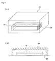
Fig. 2. Fig. 2 illustrates a tray accommodating the mixture of the phosphor raw materials, together with the container that functions as the lid, whereinFig. 2(A) is a perspective view thereof, andFig. 2(B) is a sectional view thereof.
As illustrated inFigs.2(A) (B) , themixture 16 of the phosphor raw materials is accommodated in a box-shapedtray 20, with an upper side opened. Thistray 20 is constituted of the same material as that of thecrucible 11, and is constituted of, for example, BN (boron nitride). The lid of thetray 20 may be formed into a plate-like shape to cover an upper side opening part of thetray 20. However, as illustrated inFig. 2 , by using a box-shapedcontainer 21 with a lower side opened, it may also be possible to cover thetray 20 by thiscontainer 21 so as to accommodate thetray 20 in thiscontainer 21. In this case, it is preferable to use the box-shapedcontainer 21 having the inner dimension of approximately the same dimension to about twice the outer dimension of thetray 20. - This embodiment provides the manufacturing method capable of particularly suppressing the deterioration of the emission intensity, in the phosphor containing the nitrogen like the nitride or the oxynitride. Although not clarified, the reason therefore is considered as follows.
This is because in the nitride phosphor, by mixing of the oxygen, oxygen atoms with different ion radius are replaced with a site of nitrogen atoms, and its crystal structure is collapsed, or by replacing nitrogen atoms having tervalent valency with oxygen atoms having bivalent valency, balance of the valency is collapsed, thus allowing a crystal defect to occur, resulting in the deterioration of the emission intensity of the phosphor. In the oxynitride phosphor also, it appears that the ratio of the oxygen atoms to the nitrogen atoms is collapsed and is deviated from the oxygen/nitrogen ratio capable of maintaining an optimal crystal structure, resulting in the collapse of the crystal structure, and also the nitrogen atoms having tevalent valency are replaced with the oxygen atoms having bivalent valency, and this causes the collapse of the balance of valency and crystal defect to occur, resulting in the deterioration of the emission intensity of the phosphor.
In addition, if the carbon, etc, flied from the furnace is mixed in the phosphor sample, this carbon absorbs the light emitted from the phosphor and absorbs the light emitted for exciting the phosphor. Therefore, it appears that total excitation energy can not be used for exciting the phosphor, thus inviting the substantial deterioration of the output of the light emitted from the phosphor. Moreover, it appears that reaction occurs between the carbon mixed in the phosphor sample and the phosphor sample during firing, and the carbon atoms are diffused and advanced into the phosphor sample, which are then taken in the phosphor sample as impurity atoms, thus causing the deterioration of the emission intensity to occur. In a case of a substance originally containing a plurality of oxygen atoms in the phosphor sample like the oxide phosphor, a slight amount of carbon reacts with the oxygen atoms in the sample to become CO2 and is removed. Therefore it can be estimated that the oxide phosphor is not affected so much by a contamination of the carbon in the furnace. However, in a case of a substance originally having less content of oxygen atoms like the oxynitride phosphor with less content of oxygen, it appears that the carbon in the furnace remains as it is in the sample, and therefore the nitride phosphor seems to be easily affected by the contamination of the carbon.
In addition, it appears that impurity elements such as Fe, Co, Ni that are possibly generated from the member in the furnace are mixed and taken into the phosphor sample to deteriorate the emission intensity, or residues of the decomposed raw materials remained in the furnace are mixed in and react with the phosphor sample, and the elements present in the residues are taken into the phosphor sample as impurity elements to cause the deterioration of the emission intensity to occur.
Namely, according to the manufacturing method of the present invention, it is possible to prevent mixing of the impurity elements such as oxygen, carbon, Fe, Co, Ni, and the residues of decomposed raw materials, and therefore the deterioration of the emission intensity caused thereby can be suppressed. - In any case, the manufacturing method according to this embodiment is an excellent manufacturing method capable of increasing the emission intensity of the nitride or oxynitride phosphor by about 20%, while this is an industrially easy method.
Note that this embodiment shows the manufacturing method suitable as the manufacturing method of the nitride or oxynitride phosphor, and CaAlSiOoN3-2/3o is given as an example of the phosphor. However, the present invention is not limited to this phosphor. The aforementioned method can be applied to publicly-known Ca2Si5N8:Eu, Sr2Si5N8:Eu, Ba2Si5N8:Eu, (Ca, Sr, Ba)2Si5N8:Eu, CaAl2Si4N8:Eu, CaSiN2:Eu, MwAlxSiyBzN((2/3)w + x + (4/3)y + z) as the nitride phosphor, and can be applied to Cax(Al, Si)12(O, N)16:Eu(0 < x ≤ 1.5), CaSi2O2N2:Eu, SrSi2O2N2:Eu, BaSi2O2N2:Eu, (Ca, Sr, Ba)Si2O2N2:Eu, 2.75SrO•Si3N4:Eu, SrAlxSi4-xOxN7-x:Ce, SrAlxSi6-xO1+xN8-x:Eu, SrAl19Si9ON31:Eu, LaAlSi6-zAlzN10-zOz:Ce, Si6-zAlzOzN8-z:Eu as the oxynitride phosphor. - In combination with a light emission part (particularly the light emission part that emits light in the wavelength range from 250 to 550nm) by a publicly-known method, the phosphor in a powder state manufactured by the manufacturing method according to this embodiment has the excitation band in a broad wavelength range in which the light emission part emits light, and light emission is performed by this phosphor. Therefore, it is possible to obtain a light source with high light emission efficiency that emits a visible light or white light. Particularly, in combination with the LED that emits light in the wavelength range from 250 to 550nm as the light emission part by the publicly-known method, it is possible to obtain the LED with high emission efficiency that emits the visible light or white light.
- Accordingly, this light source (LED) can be used as a display device such as CRT and PDP, and various light sources of an illumination device such as a fluorescent lamp.
- The present invention will be specifically described hereunder, based on examples.
- Commercially available Ca3N2(2N), AlN(3N), Si3N4(3N), Eu2O3(3N) were prepared, and each raw material was weighed so that the molar ratio of each element was Ca : Al : Si : Eu = 0.985 : 1 : 1 : 0.015, and was mixed by using the mortar in a glove box in the nitrogen atmosphere. The crucible made of boron nitride (having inner diameter 30mm, outer diameter 36mm, height 27mm) was filled with the mixed raw materials, and this crucible was covered with the boron nitride container one size larger than the boron nitride crucible (having inner diameter 40mm, outer diameter 46mm, height 39mm), and the boron nitride crucible covered with one size larger boron nitride container as the lid was disposed in the furnace. Here, these firing containers covered with lids were disposed on the carbon table with heights adjusted so that a position of each firing container suits a heater part, and each firing container was disposed in the furnace in a state of being put in a cylindrical carbon container having outer diameter 145mm, inner diameter 139mm, and height 210mm.
- Next, after inside of the furnace was vacuumized and replaced with nitrogen, the temperature was increased up to 1500°C at 15°C/min with an in-furnace pressure set at 0.05MPa in a circulating nitrogen atmosphere (in a flow state of 20.0L/min), and the raw materials were retained and fired for 3 hours at 1500°C. Thereafter, the temperature was lowered from 1500°C to 50°C for 1 hour and 30 minutes, and the firing was completed. Then, fired samples were pulverized by using the mortar in the atmospheric air, up to about 7µm of the average particle size, and the phosphor sample according to an example 1 was obtained.
- The obtained phosphor powder was irradiated with monochromatic light of 460nm, and the emission intensity was measured. However, the emission intensity is shown by relative intensity, which is a standardized value with the emission intensity of the phosphor in a comparative example 1 as will be described later set as 100%. This measurement result is shown in table 1. Also, the oxygen content and the carbon content obtained by chemical analysis were 2.69wt% and 0.052wt% respectively. This analysis result is shown in table 2. Note that the composition formula of this phosphor calculated from the analysis result was CaAlSiO0.22N2.85:Eu.
-
(Table 1) Relative emission intensity Peak wavelength (%) (nm) Example 1 119.8 660.0 Comparative example 1 100.0 654.5 -
(Table 2) Oxygen content Carbon content (wt%) (wt%) Example 1 2.69 0.052 Comparative example 1 2.92 0.062 - Commercially available Ca3N2(2N), AlN(3N), Si3N4(3N), Eu2O3(3N) were prepared, and each raw material was weighed so that the molar ratio of each element was Ca : Al : Si : Eu = 0.985 : 1 : 1 : 0.015, and was mixed by using the mortar in the glove box in the nitrogen atmosphere. The crucible made of boron nitride (having inner diameter 30mm, outer diameter 36mm, height 27mm) was filled with the mixed raw materials, and was disposed in the furnace in a state of not covering the crucible made of boron nitride with a lid. Here, these firing containers were disposed on the carbon table with heights adjusted so that a position of each firing container suits a heater part, and each firing container was disposed in the furnace in a state of being put in a cylindrical carbon container having outer diameter 145mm, inner diameter 139mm, and height 210mm.
Next, after the inside of the furnace was vacuumized and replaced with nitrogen, the temperature was increased up to 1500°C at 15°C/min with an in-furnace pressure set at 0.05MPa in a circulating nitrogen atmosphere (in a flow state of 20.0L/min), and the raw materials were retained and fired for 3 hours at 1500°C. Thereafter, the temperature was lowered from 1500°C to 50°C for 1 hour and 30 minutes, and the firing was completed. Then, the fired samples were pulverized by using the mortar in the atmospheric air up to about 7µm of the average particle size, and the phosphor sample according to a comparative example 1 was obtained. - The obtained phosphor powder was irradiated with monochromatic light of 460nm, and the emission intensity was measured. This measurement result is shown in table 1. Also, the oxygen content and the carbon content obtained by chemical analysis were 2.92wt% and 0.062wt% respectively. This analysis result is shown in table 2. Note that the composition formula of this phosphor calculated from the analysis result was CaAlSiO0.26N2.83:Eu.
- As shown in the table 1, the result was that the emission intensity of the phosphor in the example 1 obtained by firing the raw materials with the boron nitride crucible, being the firing container, covered with a lid, was higher by about 20% than the emission intensity of the phosphor in the comparative example 1 obtained by firing the raw materials with the crucible not covered with a lid. It appears that the emission intensity is improved by low contents of oxygen and carbon, because the oxygen content and the carbon content are low in the phosphor fired in a state of covering the crucible with a lid. Therefore, the manufacturing method of the phosphor according to this embodiment is the excellent manufacturing method capable of improving the emission efficiency of the phosphor, while this is an industrially easy method.
-
-
Fig. 1 is a perspective view illustrating a procedure of accommodating a firing container (crucible) in a container that functions as a lid, and placing this firing container and the container that functions as a lid in a firing furnace. -
Fig. 2 is a view illustrating a tray in which a mixture of phosphor raw materials are accommodated, together with the container that functions as a lid, andFig. 2(A) is a perspective view, andFig. 2(B) is a sectional view. -
- 10
- Container (container used as a lid)
- 11
- Firing container (crucible)
- 14
- Firing furnace
Claims (7)
- A manufacturing method of a nitride phosphor or an oxynitride phosphor, wherein raw material powders are put in a firing container made of nitride and these raw material powders are fired, with this firing container covered with a lid.
- The manufacturing method of the nitride phosphor or the oxynitride phosphor according to claim 1, wherein the firing container made of nitride is the firing container made of boron nitride.
- The manufacturing method of the nitride phosphor or the oxynitride phosphor according to claim 1 or 2, wherein the lid is a lid made of boron nitride.
- The manufacturing method of the nitride phosphor or the oxynitride phosphor according to any one of claims 1 to 3, wherein the phosphor is expressed by a general composition formula MABOoN3-2/3o :Z in which element M is one or more kinds of elements having bivalent valency, element A is one or more kinds of elements having tervalent valency, element B is one or more kinds of elements having tetravalent valency, O is oxygen, N is nitrogen, and element Z is an activating agent, satisfying o ≥ 0.
- The manufacturing method of the nitride phosphor or the oxynitride phosphor according to claim 4, wherein the element M is one or more kinds of elements selected from a group consisting of Mg, Ca, Sr, Ba, Zn, the element A is one or more kinds of elements selected from a group consisting of B (boron) , Al, Ga, the element B is Si and/or Ge, and the element Z is one or more kinds of elements selected from a group consisting of rare earth elements and transitional metal elements.
- The manufacturing method of the nitride phosphor or the oxynitride phosphor according to claim 4 or 5, wherein the element A is Al, and the element B is Si.
- The manufacturing method of the nitride phosphor or the oxynitride phosphor according to any one of claims 4 to 6, wherein the element M is Ca, and the element Z is Eu.
Applications Claiming Priority (2)
| Application Number | Priority Date | Filing Date | Title |
|---|---|---|---|
| JP2006269796A JP5378644B2 (en) | 2006-09-29 | 2006-09-29 | Method for producing nitride phosphor or oxynitride phosphor |
| PCT/JP2007/067536 WO2008041452A1 (en) | 2006-09-29 | 2007-09-07 | Process for producing nitride phosphor or oxonitride phosphor |
Publications (3)
| Publication Number | Publication Date |
|---|---|
| EP2075312A1 true EP2075312A1 (en) | 2009-07-01 |
| EP2075312A4 EP2075312A4 (en) | 2010-05-19 |
| EP2075312B1 EP2075312B1 (en) | 2013-03-06 |
Family
ID=39268316
Family Applications (1)
| Application Number | Title | Priority Date | Filing Date |
|---|---|---|---|
| EP07806968A Active EP2075312B1 (en) | 2006-09-29 | 2007-09-07 | Manufacturing method of nitride phosphor or oxynitride phosphor |
Country Status (7)
| Country | Link |
|---|---|
| US (1) | US9683168B2 (en) |
| EP (1) | EP2075312B1 (en) |
| JP (1) | JP5378644B2 (en) |
| KR (1) | KR101190922B1 (en) |
| CN (1) | CN101522858B (en) |
| TW (1) | TWI458805B (en) |
| WO (1) | WO2008041452A1 (en) |
Cited By (2)
| Publication number | Priority date | Publication date | Assignee | Title |
|---|---|---|---|---|
| US8638046B2 (en) * | 2009-03-23 | 2014-01-28 | Samsung Electronics Co., Ltd. | Light emitting device, light emitting system comprising the same, and method of fabricating thereof |
| JP2014181260A (en) * | 2013-03-18 | 2014-09-29 | Toshiba Corp | Phosphor, light-emitting device and method for producing phosphor |
Families Citing this family (9)
| Publication number | Priority date | Publication date | Assignee | Title |
|---|---|---|---|---|
| JP5446066B2 (en) * | 2006-12-28 | 2014-03-19 | 日亜化学工業株式会社 | Nitride phosphor and light emitting device using the same |
| WO2010002015A1 (en) * | 2008-07-02 | 2010-01-07 | ソニー株式会社 | Red phosphor, method for producing red phosphor, white light source, illuminating device, and liquid crystal display device |
| US8926864B2 (en) | 2010-05-13 | 2015-01-06 | Denki Kagaku Kogyo Kabushiki Kaisha | Method of producing β-SiAION, β-SiAION, and products using the same |
| JP2012057070A (en) * | 2010-09-09 | 2012-03-22 | Denki Kagaku Kogyo Kk | METHOD FOR PRODUCING Eu-DOPED β-TYPE SIALON |
| JP2012153873A (en) * | 2011-01-04 | 2012-08-16 | Sony Chemical & Information Device Corp | Red phosphor, method for producing red phosphor, white light source, illuminating device, and liquid crystal display device |
| KR101406966B1 (en) * | 2011-02-28 | 2014-06-16 | 성균관대학교산학협력단 | Phosphor powder formed via nitridation of chlorosilcate-based phosphor, and producing method of the same |
| JP5746672B2 (en) * | 2012-09-25 | 2015-07-08 | 株式会社東芝 | Phosphor, light emitting device, and method of manufacturing phosphor |
| JP2014177601A (en) * | 2013-03-15 | 2014-09-25 | Toshiba Corp | Yellow light emitting phosphor and light emitting device using the same |
| CN117285359A (en) * | 2023-08-11 | 2023-12-26 | 东莞市陶陶新材料科技有限公司 | A kind of nitride ceramic sintering method |
Citations (4)
| Publication number | Priority date | Publication date | Assignee | Title |
|---|---|---|---|---|
| JP2006052337A (en) | 2004-08-12 | 2006-02-23 | Fujikura Ltd | Sialon phosphor and method for producing the same |
| EP1710291A2 (en) | 2005-03-18 | 2006-10-11 | Fujikura, Ltd. | Light-emitting device and illumination apparatus |
| EP1734096A1 (en) | 2004-03-22 | 2006-12-20 | Fujikura Ltd. | Light-emitting device and illuminating device |
| EP1783096A1 (en) | 2004-07-30 | 2007-05-09 | National Institute for Materials Science | Alpha-sialon powder and process for producing the same |
Family Cites Families (27)
| Publication number | Priority date | Publication date | Assignee | Title |
|---|---|---|---|---|
| US3368861A (en) * | 1964-05-04 | 1968-02-13 | Bell Telephone Labor Inc | Faraday rotator utilizing terbium aluminum garnet and dysprosium aluminum garnet |
| DE2805292C2 (en) * | 1977-09-28 | 1982-03-11 | Toshiba Ceramics Co., Ltd., Tokyo | Method for producing a sintered body |
| EP0017331B1 (en) * | 1979-03-21 | 1983-06-15 | Promagco Limited | Improvements relating to hot chamber die-casting |
| US4303615A (en) * | 1980-06-02 | 1981-12-01 | Fisher Scientific Company | Crucible with lid |
| FR2607520B1 (en) * | 1986-11-27 | 1992-06-19 | Comurhex | PROCESS FOR THE PRODUCTION BY METALLOTHERMY OF PURE ALLOYS BASED ON RARE EARTHS AND TRANSITION METALS |
| EP0892099A1 (en) * | 1997-07-15 | 1999-01-20 | Mitsubishi Chemical Corporation | Carbon fiber woven fabric |
| EP1104799A1 (en) | 1999-11-30 | 2001-06-06 | Patent-Treuhand-Gesellschaft für elektrische Glühlampen mbH | Red emitting luminescent material |
| JP3763719B2 (en) | 2000-02-02 | 2006-04-05 | 独立行政法人科学技術振興機構 | Phosphors based on oxynitride glass |
| JP3726131B2 (en) | 2002-05-23 | 2005-12-14 | 独立行政法人物質・材料研究機構 | Sialon phosphor |
| DE10133352A1 (en) | 2001-07-16 | 2003-02-06 | Patent Treuhand Ges Fuer Elektrische Gluehlampen Mbh | Lighting unit with at least one LED as a light source |
| JP4009828B2 (en) | 2002-03-22 | 2007-11-21 | 日亜化学工業株式会社 | Nitride phosphor and method of manufacturing the same |
| JP4207489B2 (en) | 2002-08-06 | 2009-01-14 | 株式会社豊田中央研究所 | α-sialon phosphor |
| JP4834827B2 (en) * | 2003-10-03 | 2011-12-14 | 独立行政法人物質・材料研究機構 | Oxynitride phosphor |
| JP4362625B2 (en) * | 2004-02-18 | 2009-11-11 | 独立行政法人物質・材料研究機構 | Method for manufacturing phosphor |
| JP4511849B2 (en) | 2004-02-27 | 2010-07-28 | Dowaエレクトロニクス株式会社 | Phosphor and its manufacturing method, light source, and LED |
| TWI262609B (en) * | 2004-02-27 | 2006-09-21 | Dowa Mining Co | Phosphor and manufacturing method thereof, and light source, LED using said phosphor |
| JP5016187B2 (en) * | 2004-07-14 | 2012-09-05 | Dowaエレクトロニクス株式会社 | Nitride phosphor, method for producing nitride phosphor, light source and LED using the nitride phosphor |
| JP4128564B2 (en) * | 2004-04-27 | 2008-07-30 | 松下電器産業株式会社 | Light emitting device |
| JP4414821B2 (en) | 2004-06-25 | 2010-02-10 | Dowaエレクトロニクス株式会社 | Phosphor, light source and LED |
| JP4933739B2 (en) * | 2004-08-02 | 2012-05-16 | Dowaホールディングス株式会社 | Phosphor and phosphor film for electron beam excitation, and color display device using them |
| US7138756B2 (en) * | 2004-08-02 | 2006-11-21 | Dowa Mining Co., Ltd. | Phosphor for electron beam excitation and color display device using the same |
| WO2006080535A1 (en) * | 2005-01-31 | 2006-08-03 | Ube Industries, Ltd. | Nitride red phosphor and process for producing the same |
| CN102585810A (en) * | 2005-02-28 | 2012-07-18 | 电气化学工业株式会社 | Fluorescent substance and process for producing the same, and luminescent element using the same |
| JP4788944B2 (en) * | 2005-03-18 | 2011-10-05 | 株式会社フジクラ | Powdered phosphor, method for manufacturing the same, light emitting device, and lighting apparatus |
| US7443094B2 (en) * | 2005-03-31 | 2008-10-28 | Dowa Electronics Materials Co., Ltd. | Phosphor and manufacturing method of the same, and light emitting device using the phosphor |
| JP5130640B2 (en) * | 2005-04-01 | 2013-01-30 | 三菱化学株式会社 | Method for manufacturing phosphor |
| JP2008050496A (en) * | 2006-08-25 | 2008-03-06 | Sony Corp | Luminescent composition, light source device, and display device |
-
2006
- 2006-09-29 JP JP2006269796A patent/JP5378644B2/en active Active
-
2007
- 2007-09-07 US US12/310,673 patent/US9683168B2/en active Active
- 2007-09-07 WO PCT/JP2007/067536 patent/WO2008041452A1/en not_active Ceased
- 2007-09-07 CN CN200780036140.2A patent/CN101522858B/en active Active
- 2007-09-07 EP EP07806968A patent/EP2075312B1/en active Active
- 2007-09-07 KR KR1020097008700A patent/KR101190922B1/en active Active
- 2007-09-28 TW TW096136154A patent/TWI458805B/en active
Patent Citations (4)
| Publication number | Priority date | Publication date | Assignee | Title |
|---|---|---|---|---|
| EP1734096A1 (en) | 2004-03-22 | 2006-12-20 | Fujikura Ltd. | Light-emitting device and illuminating device |
| EP1783096A1 (en) | 2004-07-30 | 2007-05-09 | National Institute for Materials Science | Alpha-sialon powder and process for producing the same |
| JP2006052337A (en) | 2004-08-12 | 2006-02-23 | Fujikura Ltd | Sialon phosphor and method for producing the same |
| EP1710291A2 (en) | 2005-03-18 | 2006-10-11 | Fujikura, Ltd. | Light-emitting device and illumination apparatus |
Non-Patent Citations (1)
| Title |
|---|
| See also references of WO2008041452A1 |
Cited By (2)
| Publication number | Priority date | Publication date | Assignee | Title |
|---|---|---|---|---|
| US8638046B2 (en) * | 2009-03-23 | 2014-01-28 | Samsung Electronics Co., Ltd. | Light emitting device, light emitting system comprising the same, and method of fabricating thereof |
| JP2014181260A (en) * | 2013-03-18 | 2014-09-29 | Toshiba Corp | Phosphor, light-emitting device and method for producing phosphor |
Also Published As
| Publication number | Publication date |
|---|---|
| TWI458805B (en) | 2014-11-01 |
| CN101522858B (en) | 2014-03-12 |
| EP2075312A4 (en) | 2010-05-19 |
| US20100001234A1 (en) | 2010-01-07 |
| US9683168B2 (en) | 2017-06-20 |
| JP5378644B2 (en) | 2013-12-25 |
| TW200831639A (en) | 2008-08-01 |
| WO2008041452A1 (en) | 2008-04-10 |
| KR20090079218A (en) | 2009-07-21 |
| EP2075312B1 (en) | 2013-03-06 |
| JP2008088266A (en) | 2008-04-17 |
| CN101522858A (en) | 2009-09-02 |
| KR101190922B1 (en) | 2012-10-12 |
Similar Documents
| Publication | Publication Date | Title |
|---|---|---|
| EP2075312B1 (en) | Manufacturing method of nitride phosphor or oxynitride phosphor | |
| EP1630219B1 (en) | Phosphor and manufacturing mehod for the same, and light source using the same | |
| KR101320290B1 (en) | Phosphor and method for production thereof, and light source | |
| KR101120155B1 (en) | Fluorescent substance, fluorescent sheets, process for production of the fluorescent substance, and light-emitting devices made by using the substance | |
| KR101147560B1 (en) | Fluorescent substance and light-emitting equipment | |
| EP2275511B1 (en) | Phosphor, LED and light source | |
| EP2360227A1 (en) | Phosphor and production method of the same, method of shifting emission wavelength of phosphor, and light source and LED | |
| EP1967565A2 (en) | Red emitting nitride fluorescent material and white light emitting device using the same | |
| US7892451B2 (en) | Phosphor |
Legal Events
| Date | Code | Title | Description |
|---|---|---|---|
| PUAI | Public reference made under article 153(3) epc to a published international application that has entered the european phase |
Free format text: ORIGINAL CODE: 0009012 |
|
| 17P | Request for examination filed |
Effective date: 20090409 |
|
| AK | Designated contracting states |
Kind code of ref document: A1 Designated state(s): AT BE BG CH CY CZ DE DK EE ES FI FR GB GR HU IE IS IT LI LT LU LV MC MT NL PL PT RO SE SI SK TR |
|
| AX | Request for extension of the european patent |
Extension state: AL BA HR MK RS |
|
| A4 | Supplementary search report drawn up and despatched |
Effective date: 20100416 |
|
| TPAC | Observations filed by third parties |
Free format text: ORIGINAL CODE: EPIDOSNTIPA |
|
| DAX | Request for extension of the european patent (deleted) | ||
| 17Q | First examination report despatched |
Effective date: 20110418 |
|
| REG | Reference to a national code |
Ref country code: DE Ref legal event code: R079 Ref document number: 602007028920 Country of ref document: DE Free format text: PREVIOUS MAIN CLASS: C09K0011080000 Ipc: C09K0011640000 |
|
| RIC1 | Information provided on ipc code assigned before grant |
Ipc: C09K 11/64 20060101AFI20120612BHEP |
|
| GRAP | Despatch of communication of intention to grant a patent |
Free format text: ORIGINAL CODE: EPIDOSNIGR1 |
|
| RIN1 | Information on inventor provided before grant (corrected) |
Inventor name: SAKANE, KENJI Inventor name: GOTOH, MASAHIRO |
|
| GRAS | Grant fee paid |
Free format text: ORIGINAL CODE: EPIDOSNIGR3 |
|
| GRAA | (expected) grant |
Free format text: ORIGINAL CODE: 0009210 |
|
| AK | Designated contracting states |
Kind code of ref document: B1 Designated state(s): AT BE BG CH CY CZ DE DK EE ES FI FR GB GR HU IE IS IT LI LT LU LV MC MT NL PL PT RO SE SI SK TR |
|
| REG | Reference to a national code |
Ref country code: GB Ref legal event code: FG4D |
|
| REG | Reference to a national code |
Ref country code: CH Ref legal event code: EP Ref country code: AT Ref legal event code: REF Ref document number: 599621 Country of ref document: AT Kind code of ref document: T Effective date: 20130315 |
|
| REG | Reference to a national code |
Ref country code: IE Ref legal event code: FG4D |
|
| REG | Reference to a national code |
Ref country code: DE Ref legal event code: R096 Ref document number: 602007028920 Country of ref document: DE Effective date: 20130502 |
|
| REG | Reference to a national code |
Ref country code: AT Ref legal event code: MK05 Ref document number: 599621 Country of ref document: AT Kind code of ref document: T Effective date: 20130306 |
|
| PG25 | Lapsed in a contracting state [announced via postgrant information from national office to epo] |
Ref country code: BG Free format text: LAPSE BECAUSE OF FAILURE TO SUBMIT A TRANSLATION OF THE DESCRIPTION OR TO PAY THE FEE WITHIN THE PRESCRIBED TIME-LIMIT Effective date: 20130606 Ref country code: SE Free format text: LAPSE BECAUSE OF FAILURE TO SUBMIT A TRANSLATION OF THE DESCRIPTION OR TO PAY THE FEE WITHIN THE PRESCRIBED TIME-LIMIT Effective date: 20130306 Ref country code: ES Free format text: LAPSE BECAUSE OF FAILURE TO SUBMIT A TRANSLATION OF THE DESCRIPTION OR TO PAY THE FEE WITHIN THE PRESCRIBED TIME-LIMIT Effective date: 20130617 Ref country code: AT Free format text: LAPSE BECAUSE OF FAILURE TO SUBMIT A TRANSLATION OF THE DESCRIPTION OR TO PAY THE FEE WITHIN THE PRESCRIBED TIME-LIMIT Effective date: 20130306 Ref country code: LT Free format text: LAPSE BECAUSE OF FAILURE TO SUBMIT A TRANSLATION OF THE DESCRIPTION OR TO PAY THE FEE WITHIN THE PRESCRIBED TIME-LIMIT Effective date: 20130306 |
|
| REG | Reference to a national code |
Ref country code: NL Ref legal event code: VDEP Effective date: 20130306 |
|
| REG | Reference to a national code |
Ref country code: LT Ref legal event code: MG4D |
|
| PG25 | Lapsed in a contracting state [announced via postgrant information from national office to epo] |
Ref country code: FI Free format text: LAPSE BECAUSE OF FAILURE TO SUBMIT A TRANSLATION OF THE DESCRIPTION OR TO PAY THE FEE WITHIN THE PRESCRIBED TIME-LIMIT Effective date: 20130306 Ref country code: SI Free format text: LAPSE BECAUSE OF FAILURE TO SUBMIT A TRANSLATION OF THE DESCRIPTION OR TO PAY THE FEE WITHIN THE PRESCRIBED TIME-LIMIT Effective date: 20130306 Ref country code: LV Free format text: LAPSE BECAUSE OF FAILURE TO SUBMIT A TRANSLATION OF THE DESCRIPTION OR TO PAY THE FEE WITHIN THE PRESCRIBED TIME-LIMIT Effective date: 20130306 Ref country code: GR Free format text: LAPSE BECAUSE OF FAILURE TO SUBMIT A TRANSLATION OF THE DESCRIPTION OR TO PAY THE FEE WITHIN THE PRESCRIBED TIME-LIMIT Effective date: 20130607 |
|
| PG25 | Lapsed in a contracting state [announced via postgrant information from national office to epo] |
Ref country code: BE Free format text: LAPSE BECAUSE OF FAILURE TO SUBMIT A TRANSLATION OF THE DESCRIPTION OR TO PAY THE FEE WITHIN THE PRESCRIBED TIME-LIMIT Effective date: 20130306 |
|
| PG25 | Lapsed in a contracting state [announced via postgrant information from national office to epo] |
Ref country code: PT Free format text: LAPSE BECAUSE OF FAILURE TO SUBMIT A TRANSLATION OF THE DESCRIPTION OR TO PAY THE FEE WITHIN THE PRESCRIBED TIME-LIMIT Effective date: 20130708 Ref country code: EE Free format text: LAPSE BECAUSE OF FAILURE TO SUBMIT A TRANSLATION OF THE DESCRIPTION OR TO PAY THE FEE WITHIN THE PRESCRIBED TIME-LIMIT Effective date: 20130306 Ref country code: NL Free format text: LAPSE BECAUSE OF FAILURE TO SUBMIT A TRANSLATION OF THE DESCRIPTION OR TO PAY THE FEE WITHIN THE PRESCRIBED TIME-LIMIT Effective date: 20130306 Ref country code: SK Free format text: LAPSE BECAUSE OF FAILURE TO SUBMIT A TRANSLATION OF THE DESCRIPTION OR TO PAY THE FEE WITHIN THE PRESCRIBED TIME-LIMIT Effective date: 20130306 Ref country code: IS Free format text: LAPSE BECAUSE OF FAILURE TO SUBMIT A TRANSLATION OF THE DESCRIPTION OR TO PAY THE FEE WITHIN THE PRESCRIBED TIME-LIMIT Effective date: 20130706 Ref country code: CZ Free format text: LAPSE BECAUSE OF FAILURE TO SUBMIT A TRANSLATION OF THE DESCRIPTION OR TO PAY THE FEE WITHIN THE PRESCRIBED TIME-LIMIT Effective date: 20130306 Ref country code: RO Free format text: LAPSE BECAUSE OF FAILURE TO SUBMIT A TRANSLATION OF THE DESCRIPTION OR TO PAY THE FEE WITHIN THE PRESCRIBED TIME-LIMIT Effective date: 20130306 |
|
| PG25 | Lapsed in a contracting state [announced via postgrant information from national office to epo] |
Ref country code: PL Free format text: LAPSE BECAUSE OF FAILURE TO SUBMIT A TRANSLATION OF THE DESCRIPTION OR TO PAY THE FEE WITHIN THE PRESCRIBED TIME-LIMIT Effective date: 20130306 Ref country code: CY Free format text: LAPSE BECAUSE OF FAILURE TO SUBMIT A TRANSLATION OF THE DESCRIPTION OR TO PAY THE FEE WITHIN THE PRESCRIBED TIME-LIMIT Effective date: 20130306 |
|
| PLBE | No opposition filed within time limit |
Free format text: ORIGINAL CODE: 0009261 |
|
| STAA | Information on the status of an ep patent application or granted ep patent |
Free format text: STATUS: NO OPPOSITION FILED WITHIN TIME LIMIT |
|
| PG25 | Lapsed in a contracting state [announced via postgrant information from national office to epo] |
Ref country code: DK Free format text: LAPSE BECAUSE OF FAILURE TO SUBMIT A TRANSLATION OF THE DESCRIPTION OR TO PAY THE FEE WITHIN THE PRESCRIBED TIME-LIMIT Effective date: 20130306 |
|
| 26N | No opposition filed |
Effective date: 20131209 |
|
| PG25 | Lapsed in a contracting state [announced via postgrant information from national office to epo] |
Ref country code: IT Free format text: LAPSE BECAUSE OF FAILURE TO SUBMIT A TRANSLATION OF THE DESCRIPTION OR TO PAY THE FEE WITHIN THE PRESCRIBED TIME-LIMIT Effective date: 20130306 |
|
| REG | Reference to a national code |
Ref country code: DE Ref legal event code: R097 Ref document number: 602007028920 Country of ref document: DE Effective date: 20131209 |
|
| PG25 | Lapsed in a contracting state [announced via postgrant information from national office to epo] |
Ref country code: MC Free format text: LAPSE BECAUSE OF FAILURE TO SUBMIT A TRANSLATION OF THE DESCRIPTION OR TO PAY THE FEE WITHIN THE PRESCRIBED TIME-LIMIT Effective date: 20130306 |
|
| REG | Reference to a national code |
Ref country code: CH Ref legal event code: PL |
|
| REG | Reference to a national code |
Ref country code: IE Ref legal event code: MM4A |
|
| PG25 | Lapsed in a contracting state [announced via postgrant information from national office to epo] |
Ref country code: IE Free format text: LAPSE BECAUSE OF NON-PAYMENT OF DUE FEES Effective date: 20130907 Ref country code: CH Free format text: LAPSE BECAUSE OF NON-PAYMENT OF DUE FEES Effective date: 20130930 Ref country code: LI Free format text: LAPSE BECAUSE OF NON-PAYMENT OF DUE FEES Effective date: 20130930 |
|
| PG25 | Lapsed in a contracting state [announced via postgrant information from national office to epo] |
Ref country code: MT Free format text: LAPSE BECAUSE OF FAILURE TO SUBMIT A TRANSLATION OF THE DESCRIPTION OR TO PAY THE FEE WITHIN THE PRESCRIBED TIME-LIMIT Effective date: 20130306 Ref country code: TR Free format text: LAPSE BECAUSE OF FAILURE TO SUBMIT A TRANSLATION OF THE DESCRIPTION OR TO PAY THE FEE WITHIN THE PRESCRIBED TIME-LIMIT Effective date: 20130306 |
|
| REG | Reference to a national code |
Ref country code: DE Ref legal event code: R082 Ref document number: 602007028920 Country of ref document: DE Representative=s name: MUELLER-BORE & PARTNER PATENTANWAELTE PARTG MB, DE Ref country code: DE Ref legal event code: R081 Ref document number: 602007028920 Country of ref document: DE Owner name: CITIZEN ELECTRONICS CO., LTD., FUJIYOSHIDA-SHI, JP Free format text: FORMER OWNER: DOWA ELECTRONICS MATERIALS CO., LTD., TOKYO, JP Ref country code: DE Ref legal event code: R081 Ref document number: 602007028920 Country of ref document: DE Owner name: NICHIA CORP., ANAN-SHI, JP Free format text: FORMER OWNER: DOWA ELECTRONICS MATERIALS CO., LTD., TOKYO, JP |
|
| PG25 | Lapsed in a contracting state [announced via postgrant information from national office to epo] |
Ref country code: HU Free format text: LAPSE BECAUSE OF FAILURE TO SUBMIT A TRANSLATION OF THE DESCRIPTION OR TO PAY THE FEE WITHIN THE PRESCRIBED TIME-LIMIT; INVALID AB INITIO Effective date: 20070907 Ref country code: LU Free format text: LAPSE BECAUSE OF NON-PAYMENT OF DUE FEES Effective date: 20130907 |
|
| REG | Reference to a national code |
Ref country code: FR Ref legal event code: PLFP Year of fee payment: 9 |
|
| REG | Reference to a national code |
Ref country code: GB Ref legal event code: 732E Free format text: REGISTERED BETWEEN 20150723 AND 20150729 |
|
| REG | Reference to a national code |
Ref country code: FR Ref legal event code: TQ Owner name: NICHIA CORPORATION, JP Effective date: 20151023 Ref country code: FR Ref legal event code: TQ Owner name: CITIZEN ELECTRONICS CO., LTD., JP Effective date: 20151023 |
|
| REG | Reference to a national code |
Ref country code: FR Ref legal event code: PLFP Year of fee payment: 10 |
|
| REG | Reference to a national code |
Ref country code: FR Ref legal event code: PLFP Year of fee payment: 11 |
|
| REG | Reference to a national code |
Ref country code: FR Ref legal event code: PLFP Year of fee payment: 12 |
|
| P01 | Opt-out of the competence of the unified patent court (upc) registered |
Effective date: 20230522 |
|
| PGFP | Annual fee paid to national office [announced via postgrant information from national office to epo] |
Ref country code: DE Payment date: 20250730 Year of fee payment: 19 |
|
| PGFP | Annual fee paid to national office [announced via postgrant information from national office to epo] |
Ref country code: GB Payment date: 20250731 Year of fee payment: 19 |
|
| PGFP | Annual fee paid to national office [announced via postgrant information from national office to epo] |
Ref country code: FR Payment date: 20250808 Year of fee payment: 19 |