EP2075179A2 - Motorcycle - Google Patents
Motorcycle Download PDFInfo
- Publication number
- EP2075179A2 EP2075179A2 EP08254119A EP08254119A EP2075179A2 EP 2075179 A2 EP2075179 A2 EP 2075179A2 EP 08254119 A EP08254119 A EP 08254119A EP 08254119 A EP08254119 A EP 08254119A EP 2075179 A2 EP2075179 A2 EP 2075179A2
- Authority
- EP
- European Patent Office
- Prior art keywords
- horn
- motorcycle
- opening
- inner panel
- disposed
- Prior art date
- Legal status (The legal status is an assumption and is not a legal conclusion. Google has not performed a legal analysis and makes no representation as to the accuracy of the status listed.)
- Granted
Links
Images





Classifications
-
- B—PERFORMING OPERATIONS; TRANSPORTING
- B62—LAND VEHICLES FOR TRAVELLING OTHERWISE THAN ON RAILS
- B62J—CYCLE SADDLES OR SEATS; AUXILIARY DEVICES OR ACCESSORIES SPECIALLY ADAPTED TO CYCLES AND NOT OTHERWISE PROVIDED FOR, e.g. ARTICLE CARRIERS OR CYCLE PROTECTORS
- B62J17/00—Weather guards for riders; Fairings or stream-lining parts not otherwise provided for
- B62J17/02—Weather guards for riders; Fairings or stream-lining parts not otherwise provided for shielding only the rider's front
-
- B—PERFORMING OPERATIONS; TRANSPORTING
- B62—LAND VEHICLES FOR TRAVELLING OTHERWISE THAN ON RAILS
- B62J—CYCLE SADDLES OR SEATS; AUXILIARY DEVICES OR ACCESSORIES SPECIALLY ADAPTED TO CYCLES AND NOT OTHERWISE PROVIDED FOR, e.g. ARTICLE CARRIERS OR CYCLE PROTECTORS
- B62J3/00—Acoustic signal devices; Arrangement of such devices on cycles
- B62J3/02—Mechanical devices
- B62J3/04—Mechanical devices activated by the rider, e.g. bells or horns
Definitions
- the present invention relates to a motorcycle including a horn.
- a horn of a motorcycle needs to deliver a sound at a predetermined or higher volume to a person or the like in front of the motorcycle.
- a horn of a motorcycle needs to deliver a sound at a predetermined or higher volume to a person or the like in front of the motorcycle.
- the volume of the sound emitted by the horn itself but also a mounted position of the horn is of importance.
- motorcycles which include a full cowl, i.e., having a cover for covering substantially the whole front portion of a vehicle body.
- a full cowl i.e., having a cover for covering substantially the whole front portion of a vehicle body.
- a motorcycle having a front cowl for covering front portions of handlebars an inner panel disposed to extend between positions above and behind a front wheel, and side covers disposed laterally outside the inner panel and extending rearward.
- JP 63-13392 indicates that a warning sound of the horn is not reduced because the horn faces the opening in a rectifying face of the inner panel. However, the opening is positioned immediately behind the front fork and therefore the warning sound of the horn may be reduced in reality.
- the present invention has been made with the above point of view and is to provide a motorcycle with which it is easy to secure a sufficient sound volume of a horn.
- a motorcycle comprising:
- the motorcycle may comprise a head pipe for supporting the front fork.
- the motorcycle may further comprise a front cowl for covering a front portion of the head pipe.
- the inner panel may be disposed below the front cowl.
- the motorcycle may comprise left and right side covers disposed laterally outside the inner panel to extend rearward.
- the horn may be disposed behind the inner panel.
- a horn opening may be formed in the inner panel in front of the horn.
- the horn may be disposed to face substantially forward behind the horn opening.
- the horn may be disposed so as to be spaced rearward from the horn opening.
- a cylindrical portion may be provided at a periphery of the horn opening in the inner panel.
- the cylindrical portion may extend rearward from the horn opening.
- the horn opening may be formed above a vertical middle position of the inner panel in the front view.
- the inner panel may be formed with a main opening in a position laterally inside the horn in the front view and configured to permit flowing air to pass rearward therethrough.
- the main opening may extend laterally across a lateral center of the inner panel in the front view.
- the motorcycle may further comprise a radiator disposed behind the main opening.
- the horn may be positioned laterally outside the radiator in the front view.
- the horn may be directly or indirectly supported by the radiator.
- An upper end of the horn may be positioned above an upper end of the radiator.
- the motorcycle may further comprise an engine having a cylinder at least partially positioned behind the main opening.
- the horn may be positioned laterally outside the cylinder in the front view.
- the horn opening may be formed to a lateral side of the main opening.
- One or more airflow openings may be formed below the main opening and the horn opening in the inner panel.
- the motorcycle may further comprise an exhaust pipe disposed to the right or left of a center of the motorcycle.
- the horn may be disposed on an opposite side of the exhaust pipe with respect to a lateral direction of the vehicle.
- the motorcycle may comprise a single-cylinder engine.
- the motorcycle may comprise a plurality of horns. At least two of the plurality of horns may be disposed in the same vertical position in the front view. At least two of the plurality of horns may be positioned to the right and left of a lateral center of the inner panel in the front view.
- a motorcycle according to the present invention comprises a head pipe, a front fork supported by the head pipe, a front wheel rotatably supported at a lower end portion of the front fork, a front cowl for covering a front portion of the head pipe, an inner panel disposed below the front cowl and behind the front wheel, left and right side covers disposed laterally outside the inner panel to extend rearward, and a horn positioned to overlap with the inner panel and at least partially disposed laterally outside the front fork in a front view.
- the present invention can achieve a motorcycle with which it is easy to secure a sufficient sound volume of a horn.
- a motorcycle 10 As shown in FIG. 1 , a motorcycle 10 according to a first embodiment of the invention includes a vehicle frame 24 having head pipes 11. On the vehicle frame 24, a fuel tank 26 and a seat 28 are supported. Rear arms 38 are pivotally supported by the vehicle frame 24 with a pivot shaft 36 interposed therebetween. On rear end portions of the rear arms 38, a rear wheel 34 is rotatably supported.
- the engine 30 is suspended from the vehicle frame 24, an engine 30 is suspended.
- the engine 30 is a water-cooled single-cylinder engine.
- the engine 30 may be an air-cooled engine and may be a multi-cylinder engine.
- the engine 30 has an engine body 30a and a cylinder 30b extending diagonally forward and upward from the engine body 30a.
- a water pump 30c is mounted as shown in FIG. 7 .
- an exhaust pipe 33 is disposed on a left side of the vehicle viewed from the front.
- the exhaust pipe 33 is connected to the cylinder 30b.
- a muffler 35 is mounted on a rear end portion of the exhaust pipe 33.
- front forks 14 are supported for turning by the head pipes 11.
- a handlebar 16 is mounted on upper portions of the front forks 14.
- a front wheel 12 is rotatably supported.
- the front forks 14 are also mounted with a fender 18 for covering upper end rear portions of the front wheel 12.
- a front cowl 20 is provided in front of the head pipes 11.
- the front cowl 20 is provided with a headlight 20a and a wind shielding plate 20b.
- an inner panel 42 extending between positions above and behind the front wheel 12 is disposed.
- the fender 18 is provided above and behind the front wheel 12 and therefore, the inner panel 42 is disposed to extend between positions above and behind the fender 18.
- left and right side covers 22 extending rearward are provided, respectively.
- the lateral direction in the present description refers to a lateral direction when the motorcycle 10 is viewed from the front. Therefore, the left and right are reversed when the motorcycle 10 is viewed from a rider seated on the seat 28 of the motorcycle 10.
- a left side and a right side of the vehicle refer to a left side and a right side of the vehicle with respect to a central line M1 (see FIG. 2 ).
- FIG. 3 is a front view of the inner panel 42.
- the inner panel 42 is formed with a main opening 72 extending laterally across the center (i.e., the central line M1) of the vehicle.
- the "openings in the inner panel” refer to holes formed inside and a recessed portion formed at a peripheral edge of the inner panel.
- the main opening 72 is a portion recessed downward at an upper portion of inner panel 42.
- the main opening 72 is formed above a middle position (i.e., a central line M2) in a vertical direction of the inner panel 42.
- the main opening 72 is an opening for allowing backward passage of the flowing air from the front and has a function of supplying the flowing air to a radiator 40 in the embodiment.
- the inner panel 42 is formed with airflow openings 52L, 52R and airflow openings 50L, 50R.
- the airflow opening 52L and the airflow opening 52R are formed in bilaterally symmetric positions.
- the airflow opening 50L and the airflow opening 50R are also formed in bilaterally symmetric positions.
- the airflow openings 52L, 52R are formed above the airflow openings 50L, 50R.
- the airflow openings 50L, 50R, 52L, 52R have functions of supplying flowing air to parts (e.g., the engine 30) disposed behind the inner panel 42 and in need of cooling.
- air leading faces 54L, 54R, 58L, 58R spreading toward the front of the vehicle are formed, respectively.
- the air leading faces 54L, 54R, 58L, and 58R form duct shapes tapered rearward from the front of the vehicle to thereby effectively send flowing air to the back of the inner panel 42.
- a reinforcement rib 56L is formed between the airflow opening 52L and the airflow opening 50L.
- a reinforcement rib 56R is formed.
- Under the main opening 72, a reinforcement rib 74 extending in the lateral direction is formed.
- the right air leading wall 68R is formed with a horn opening 60.
- the horn opening 60 is formed to the lateral side of the main opening 72.
- the horn opening 60 is formed above the middle position in the vertical direction of the inner panel 42 and, in the embodiment, formed between an upper end 42a of the inner panel 42 and a one-quarter position of a vertical length of the inner panel 42 from the upper end 42a.
- a position of the horn opening 60 can be changed in various ways and is not limited to the above position.
- the size of the horn opening 60 is not especially limited, the horn opening 60 is smaller than the main opening 72 in the embodiment.
- the horn opening 60 may be larger or smaller than or about the same size as any one of the airflow openings 50L, 50R, 52L, 52R.
- a shape of the horn opening 60 may be rectangular or another shape such as a circular, elliptical, polygonal or the like.
- a cylindrical portion 61 extending rearward is provided on a back side of the horn opening 60 in the inner panel 42.
- the cylindrical portion 61 is part of the inner panel 42 and is integral with the inner panel 42.
- the cylindrical portion 61 may be formed separately from the inner panel 42 and subsequently mounted on the inner panel 42.
- the cylindrical portion 61 is formed in a shape of a prismatic cylinder.
- the shape of the cylindrical portion 61 is not especially limited and may be a circular cylinder, an elliptic cylinder, a triangular cylinder, or other shapes.
- the cylindrical portion 61 extends substantially horizontally in a side view but may be slightly inclined forward or backward. As shown in FIG. 4 , the cylindrical portion 61 extends substantially horizontally in the embodiment.
- the radiator 40 is disposed behind the main opening 72 in the inner panel 42.
- the flowing air passing through the main opening 72 is supplied to the radiator 40.
- a bracket 43 is supported on a right portion of the radiator 40.
- the bracket 43 is mounted with a stay 44 for supporting a horn 70.
- the horn 70 is supported by the radiator 40 with the stay 44 and the bracket 43 interposed therebetween.
- the horn 70 is disposed behind the cylindrical portion 61 of the inner panel 42. Therefore, the horn 70 is disposed in a position spaced rearward from the horn opening 60 in the inner panel 42.
- the horn 70 is disposed to face substantially forward through the horn opening 60 so as to emit a warning sound forward through the horn opening 60. In other words, the horn 70 is disposed to face substantially forward.
- the horn 70 is oriented substantially in a direction along a longitudinal direction of the cylindrical portion 61.
- to be disposed to face substantially forward includes not only to be disposed to face forward in a strict sense but also to be regarded as being generally disposed to face forward. In other words, it includes not only to be disposed parallel to a plane formed by a horizontal line and a vertical line, i.e., a plane orthogonal to a front-rear direction of the vehicle body but also to be slightly inclined with respect to the plane.
- the horn 70 is inclined to such a degree that a left or right end and an upper or lower end of the horn 70 can be seen from the front, the horn 70 is regarded as being disposed to face substantially forward.
- an angle of inclination with respect to the plane is 30° or smaller, for example, the horn 70 is also regarded as being disposed to face substantially forward.
- the horn opening 60 and the horn 70 are disposed to the right of the main opening 72. However, part of the horn 70 may be positioned inside the main opening 72.
- the horn opening 60 and the horn 70 are disposed to the right of the radiator 40. Specifically, the horn opening 60 and the horn 70 are disposed between a right end of the radiator 40 and an outmost end 22a of the right side cover 22.
- the horn opening 60 and the horn 70 are disposed to the right of the front forks 14. Specifically, the horn opening 60 is disposed between a right end 14a of the front forks 14 and the outmost end 22a of the right side cover 22. A lateral width of the horn 70 is shorter than a distance between the right end 14a of the front forks 14 and the outmost end 22a of the right side cover 22 and the horn 70 is disposed between the right end 14a of the front forks 14 and the outmost end 22a of the right side cover 22.
- the whole horn 70 is disposed to the right of the right end 14a of the front fork 14 in the present embodiment, it is also possible that only a part of the horn 70 is positioned to the right of the right end 14a of the front fork 14.
- the horn 70 is disposed to the right of the cylinder 30b of the engine 30. Specifically, the horn 70 is disposed between a right end of the cylinder 30b and the outmost end 22a of the right side cover 22.
- the horn 70 is disposed to overlap with the inner panel 42 and to the right of the front forks 14 (i.e., on the outside in a lateral direction) in a front view. Therefore, according to the present embodiment, the sound output from the horn 70 is directly transmitted forward without interference with the front fork 14. As a result, it is possible to provide a motorcycle 10 with which a sufficient sound volume of the horn 70 can be secured. It is also possible to inhibit the horn 70 from interrupting airflow.
- the front wheel 12 has a smaller width than a front wheel of a prior-art motorcycle of this type. If the front wheel has a large width, a distance between left and right tubes of the front forks is relatively large. In this case, even if the horn is disposed inside the front fork in the lateral direction, there is no serious interference of the sound of the horn and the front forks. If the front wheel 12 has a smaller width, however, the distance between the left and right tubes of the front forks 14 is short and the sound of the horn 70 and the front fork 14s are more likely to interfere with each other without making a special arrangement as in the embodiment. As seen from the above, the smaller the width of the front wheel 12 is, the more remarkable effect the present embodiment exerts.
- the front wheel 12 has the small width as described above. Therefore, the lateral distance between the front forks 14 is short and relatively large areas are secured at portions of the inner panel 42 outside the front forks 14 in the front view. As a result, it is possible to dispose the horn 70 easily laterally outside the front fork 14 in the front view.
- the inventors of the present application focused on this point and decided to dispose the horn 70 laterally outside the front forks 14.
- the inner panel 42 (see FIG. 3 ) is formed with the main opening 72 extending laterally across the lateral center and the horn opening 60 at least partially positioned outside the main opening 72.
- the horn 70 is disposed to face substantially forward behind the horn opening 60 in the inner panel 42 (see FIGS. 4 and 5 ). Therefore, the rearward flow of the flowing air through the main opening 72 from the front of the vehicle is not disturbed by the horn 70.
- the radiator 40 is disposed behind the main opening 72 and the flow of the flowing air supplied to the radiator 40 is not disturbed by the horn 70. Therefore, reduction in the cooling performance of the radiator 40 is suppressed.
- the horn 70 is disposed to face substantially forward, the warning sound from the horn 70 is smoothly output forward. Furthermore, because the horn 70 is positioned outside the main opening 72, it is possible to suppress interference of the warning sound from the horn 70 with the front wheel 12. Therefore, it is possible to deliver the warning sound at sufficient volume to a person or the like in front of the vehicle without increasing the horn 70 itself in size. As a result, the horn 70 can be reduced in size, weight, or cost.
- the horn 70 is disposed so as to be spaced rearward from the horn opening 60 in the inner panel 42 (see FIG. 5 ). Therefore, even if mud splashed from the ground spatters around the horn opening 60, the mud is less likely to stick to the horn 70. The warning sound from the horn 70 is less likely to be weakened by the mud sticking to the horn 70.
- the cylindrical portion 61 extending rearward is formed around the horn opening 60 in the inner panel 42 (see FIG. 6 ). In this way, it is possible to further suppress sticking of the mud splashed from the ground to the horn 70. Moreover, the cylindrical portion 61 suppresses diffusion of the warning sound output from the horn 70. In other words, the cylindrical portion 61 functions as a so-called megaphone and it is possible to effectively emit the warning sound from the horn 70 forward. Moreover, the cylindrical portion 61 functions as a so-called reinforcement rib to thereby enhance strength of the inner panel 42.
- the horn opening 60 is formed above the middle position in the vertical direction of the inner panel 42 in the front view (see FIG. 3 ).
- An upper end of the horn 70 is positioned above an upper end of the radiator 40 (see FIG. 4 ). Because the horn opening 60 and the horn 70 are in high positions, mud splashed from the ground is less likely to stick to the horn 70. Moreover, because the horn opening 60 and the horn 70 are in high positions, it is possible to effectively deliver the warning sound from the horn 70 to a person or the like in front of the vehicle.
- the horn opening 60 is formed to the lateral side of the main opening 72 (see FIG. 3 ). Therefore, it is possible to secure sufficient space for forming other openings (the airflow openings 50L, 50R, 52L, 52R in the embodiment) in the inner panel 42 below the main opening 72.
- the airflow openings 50L, 50R, 52L, 52R are formed in the inner panel 42 and below the main opening 72 and the horn opening 60. Therefore, it is possible to introduce the flowing air backward from the front of the inner panel 42 through the airflow openings 50L, 50R, 52L, 52R. Therefore, it is possible to effectively cool the vehicle parts with the flowing air taken in through the airflow openings 50L, 50R, 52L, 52R while preventing sticking of mud or the like to the vehicle parts such as the engine 30 to some extent with the inner panel 42.
- the horn opening 60 and the horn 70 are disposed to the right of the front forks 14 in the front view (see FIG. 2 ). Therefore, the warning sound output from the horn 70 is not intercepted or impeded by the front forks 14. As a result, it is possible to deliver the warning sound at sufficient volume to a person or the like in front of the vehicle without increasing the horn 70 in size.
- the horn 70 need not be provided in front of the front forks 14, an interval between the front forks 14 (i.e., a fork pitch) can be shortened. In this way, it is possible to shorten a width of the front wheel 12. Moreover, it is possible to increase a steering angle of the handlebar 16 and it is possible to provide a motorcycle 10 with a small turning circle.
- the horn 70 is supported on the radiator 40 with the bracket 43 and the stay 44 interposed therebetween (see FIG. 5 ).
- the horn 70 is indirectly supported on the radiator 40.
- a member for supporting the horn 70 need not be provided to the vehicle frame 24.
- the radiator 40 is a relatively heavy and large vehicle part and is less susceptible to vibration. Therefore, by supporting the horn 70 on the radiator 40, it is possible to support the horn 70 securely. Moreover, the warning sound from the horn 70 is less liable to be attenuated by any vibrations.
- the horn 70 is supported indirectly by the radiator 40 in the embodiment, it is possible to support the horn 70 directly on the radiator 40.
- the horn 70 is disposed to the right of the middle position in the lateral direction of the vehicle and the exhaust pipe 33 is disposed to the left of it (see FIG. 2 ).
- the horn 70 By disposing the horn 70 on the opposite side to the exhaust pipe 33 in this way, it is possible to easily avoid interference of the horn 70 and the exhaust pipe 33 with each other and it is possible to relatively freely select a mounted position of the horn 70 without being restricted by the position of the exhaust pipe 33.
- the engine 30 is a single-cylinder engine. Therefore, the engine 30 has a shorter width than a parallel multi-cylinder engine. A width of the radiator 40 is short, too. Therefore, it is easy to dispose the horn opening 60 and the horn 70 to the lateral side of the main opening 72.
- a second embodiment of the present invention will mow be described with reference to FIG. 8 .
- This second embodiment is different from the first embodiment described above in that the horn opening 60 formed to the lateral side of the main opening 72 is omitted and that the airflow opening 52R is used as the horn opening.
- the airflow opening 52R in the first embodiment functions as the horn opening 60.
- a bracket (not shown) is supported by the cylinder 30b of the engine 30 and the stay 44 for the horn 70 is mounted on the bracket.
- portions are similar to those in the first embodiment. Portions similar to those in the first embodiment are provided with similar reference numerals to omit description of such similar portions.
- at least a part of the horn 70 is disposed again to overlap with the inner panel 42 and laterally outside the front forks 14 in the front view.
- a third embodiment of the present invention will now be described with reference to FIG. 9 .
- This third embodiment is different from the first embodiment in that the engine 30 is an air-cooled engine and that the radiator 40 is omitted.
- portions similar to those in the first embodiment are provided with similar reference numerals to omit description of these similar portions.
- the horn 70 is disposed to the right of the cylinder 30b of the engine 30 in the front view (see FIG. 7 ).
- the horn 70 is disposed to overlap with the inner panel 42 and laterally outside the front forks 14 in the front view.
- the flowing air passing through the main opening 72 in the inner panel 42 is supplied to the cylinder 30b of the engine 30.
- the horn opening 60 and the horn 70 are formed to the lateral side of the main opening 72.
- the horn opening 60 and the horn 70 are disposed to the right of the cylinder 30b of the engine 30. Therefore, the flow of the flowing air to be supplied to the cylinder 30b is not disturbed by the horn 70. Therefore, there is no fear that the horn 70 impairs the cooling performance of the engine 30.
- the cylindrical portion 61 is provided behind the horn opening 60 in the inner panel 42 in the above respective embodiments, the cylindrical portion 61 may be omitted as shown in FIG. 10 .
- the cylindrical portion 61 may be provided not in the position spaced rearward from the horn opening 60 but in the horn opening 60.
- the horn opening 60 and the horn 70 are provided on the right side in the front view.
- the horn opening 60 and the horn 70 may be provided on the left side in the front view.
- the horn 70 is disposed to overlap with the inner panel 42 and on the left side, that is, the outside of the front fork 14 in the lateral direction.
- the horn opening 60 and the horn 70 may be provided on each of the right side and the left side in the front view. In this case, each of the left and right horns 70 is disposed to overlap with the inner panel 42 and laterally outside the front fork 14.
- a positional relationship between the horn opening 60 and the main opening 72 is not limited to that in the above respective embodiments.
- the horn opening 60 and the main opening 72 may be displaced from each other in the vertical direction when viewed from the front. Not the whole horn opening 60 need be positioned outside the main opening 72 but only part of the horn opening 60 may be positioned outside the main opening 72 in the lateral direction.
- the horn 70 may partially overlap the front forks 14 when viewed from the front. Moreover, the horn opening 60 and the front forks may partially overlap each other when viewed from the front.
- the horn 70 may partially overlap the horn opening 60 when viewed from the front.
- the whole horn 70 may be disposed inside the horn opening 60.
- the horn opening 60 is formed of the single opening.
- the horn opening may be formed of a plurality of louver openings 60b extending in a horizontal direction.
- the horn opening may be formed of a plurality of louver openings 60c extending in a vertical direction.
- the horn opening may be formed of a plurality of small holes 60d such as so-called punched holes.
- the main opening 72 is not limited to one in the above embodiment either and there are many conceivable variations.
- the main opening 72 may be formed of louver openings, punched holes, or the like.
- the main opening 72 that lets the flowing air pass through may be replaced with a dummy opening that does not let the flowing air pass through.
- the openings in the inner panel include both the hole formed inside the inner panel (i.e., the fully enclosed opening) and the recessed portion formed at the peripheral edge of the inner panel (i.e., the partially enclosed opening).
- the virtual line L1 is a line showing a right end position of the main opening 72 in the lateral direction.
- the whole horn opening 60 is positioned to the right of the virtual line L1, which means that the whole horn opening 60 is positioned on the outside the main opening 72.
- the airflow opening 52R functions as the horn opening and is partially positioned to the left of the virtual line L1. Therefore, only part of the horn opening is positioned outside the main opening 72.
- “To be at least partially positioned outside the front forks in the lateral direction” refers to be at least partially positioned outside a virtual line L2 shown in FIG. 2 if the embodiment is taken as an example.
- the virtual line L2 is a line showing a right end position of the front forks 14 in the lateral direction.
- the whole horn opening 60 is positioned to the right of the virtual line
- the airflow opening 52R functions as the horn opening and is partially positioned to the left of the virtual line L2. Therefore, only part of the horn opening is positioned outside the front forks 14.
- the invention is useful for a motorcycle.
Landscapes
- Engineering & Computer Science (AREA)
- Mechanical Engineering (AREA)
- Physics & Mathematics (AREA)
- Acoustics & Sound (AREA)
- Automatic Cycles, And Cycles In General (AREA)
- Axle Suspensions And Sidecars For Cycles (AREA)
Abstract
Description
- The present invention relates to a motorcycle including a horn.
- A horn of a motorcycle needs to deliver a sound at a predetermined or higher volume to a person or the like in front of the motorcycle. For this purpose, not only the volume of the sound emitted by the horn itself but also a mounted position of the horn is of importance. In general, it is preferable to mount the horn on the front of the vehicle.
- Motorcycles are known which include a full cowl, i.e., having a cover for covering substantially the whole front portion of a vehicle body. Among motorcycles having full cowls, there is a motorcycle having a front cowl for covering front portions of handlebars, an inner panel disposed to extend between positions above and behind a front wheel, and side covers disposed laterally outside the inner panel and extending rearward.
- However, in such a motorcycle having a full cowl including an inner panel, if the horn is disposed in front of the inner panel, a flow of flowing air in front of the inner panel is disturbed by the horn. As a result, the flowing air for cooling may not be effectively supplied to parts (e.g., an engine in an air-cooled engine, a radiator in a water-cooled engine) disposed behind the inner panel and in need of cooling.
- In Japanese Utility Model Application Laid-open No.
63-13392 -
JP 63-13392 - The present invention has been made with the above point of view and is to provide a motorcycle with which it is easy to secure a sufficient sound volume of a horn.
- According to an aspect of the present invention there is provided a motorcycle comprising:
- a front fork rotatably supporting a front wheel at a lower end portion thereof;
- an inner panel disposed behind the front wheel; and
- a horn, at least part of which is disposed laterally outside the front fork in a position where the horn overlaps with the inner panel in a front view.
- The motorcycle may comprise a head pipe for supporting the front fork.
- The motorcycle may further comprise a front cowl for covering a front portion of the head pipe. The inner panel may be disposed below the front cowl.
- The motorcycle may comprise left and right side covers disposed laterally outside the inner panel to extend rearward.
- The horn may be disposed behind the inner panel. A horn opening may be formed in the inner panel in front of the horn.
- The horn may be disposed to face substantially forward behind the horn opening.
- The horn may be disposed so as to be spaced rearward from the horn opening.
- A cylindrical portion may be provided at a periphery of the horn opening in the inner panel. The cylindrical portion may extend rearward from the horn opening.
- The horn opening may be formed above a vertical middle position of the inner panel in the front view.
- The inner panel may be formed with a main opening in a position laterally inside the horn in the front view and configured to permit flowing air to pass rearward therethrough.
- The main opening may extend laterally across a lateral center of the inner panel in the front view.
- The motorcycle may further comprise a radiator disposed behind the main opening. The horn may be positioned laterally outside the radiator in the front view. The horn may be directly or indirectly supported by the radiator. An upper end of the horn may be positioned above an upper end of the radiator.
- The motorcycle may further comprise an engine having a cylinder at least partially positioned behind the main opening. The horn may be positioned laterally outside the cylinder in the front view.
- The horn opening may be formed to a lateral side of the main opening.
- One or more airflow openings may be formed below the main opening and the horn opening in the inner panel.
- The motorcycle may further comprise an exhaust pipe disposed to the right or left of a center of the motorcycle. The horn may be disposed on an opposite side of the exhaust pipe with respect to a lateral direction of the vehicle.
- The motorcycle may comprise a single-cylinder engine.
- The motorcycle may comprise a plurality of horns. At least two of the plurality of horns may be disposed in the same vertical position in the front view. At least two of the plurality of horns may be positioned to the right and left of a lateral center of the inner panel in the front view.
- A motorcycle according to the present invention comprises a head pipe, a front fork supported by the head pipe, a front wheel rotatably supported at a lower end portion of the front fork, a front cowl for covering a front portion of the head pipe, an inner panel disposed below the front cowl and behind the front wheel, left and right side covers disposed laterally outside the inner panel to extend rearward, and a horn positioned to overlap with the inner panel and at least partially disposed laterally outside the front fork in a front view.
- The present invention can achieve a motorcycle with which it is easy to secure a sufficient sound volume of a horn.
- These and other aspects of the present invention will now be described, by way of example only, with reference to the accompanying drawings, in which:
-
FIG. 1 is a side view of a motorcycle according to an embodiment of the present invention; -
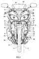
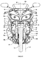
FIG. 2 is a front view of the motorcycle ofFIG. 1 ; -
FIG. 3 is a front view of an inner panel; -
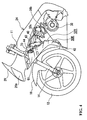
FIG. 4 is a partial side view showing an inside of the motorcycle ofFIG. 1 ; -
FIG. 5 is a partial plan view of a horn and the inner panel; -
FIG. 6 is a perspective view of the horn viewed from behind; -
FIG. 7 is a front view showing a positional relationship between an engine and the horn; -
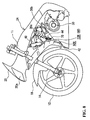
FIG. 8 is a partial side view showing an inside of a motorcycle according to another embodiment of the present invention; -
FIG. 9 is a partial side view showing an inside of a motorcycle according to a further embodiment of the present invention; -
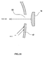
FIG. 10 is a side sectional view of an inner panel and a horn according to a variation on the previous embodiments; -
FIG. 11 is a front view of a motorcycle according to a further variation on the previous embodiments; -
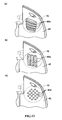
FIG. 12(a) is a perspective view showing an opening for a horn according to a further variation; -
FIG. 12(b ) is a perspective view showing an opening for a horn according to a further variation; and -
FIG. 12(c) is a perspective view showing an opening for a horn according to a still further variation. - As shown in
FIG. 1 , amotorcycle 10 according to a first embodiment of the invention includes avehicle frame 24 havinghead pipes 11. On thevehicle frame 24, afuel tank 26 and aseat 28 are supported.Rear arms 38 are pivotally supported by thevehicle frame 24 with apivot shaft 36 interposed therebetween. On rear end portions of therear arms 38, arear wheel 34 is rotatably supported. - From the
vehicle frame 24, anengine 30 is suspended. In the embodiment, theengine 30 is a water-cooled single-cylinder engine. However, theengine 30 may be an air-cooled engine and may be a multi-cylinder engine. Theengine 30 has anengine body 30a and acylinder 30b extending diagonally forward and upward from theengine body 30a. On a right side of thecylinder 30b when viewed from the front, awater pump 30c is mounted as shown inFIG. 7 . As shown inFIG. 2 , on a left side of the vehicle viewed from the front, anexhaust pipe 33 is disposed. Theexhaust pipe 33 is connected to thecylinder 30b. Amuffler 35 is mounted on a rear end portion of theexhaust pipe 33. - As shown in
FIG. 1 ,front forks 14 are supported for turning by thehead pipes 11. Ahandlebar 16 is mounted on upper portions of thefront forks 14. At lower portions of thefront forks 14, afront wheel 12 is rotatably supported. Thefront forks 14 are also mounted with afender 18 for covering upper end rear portions of thefront wheel 12. - In front of the
head pipes 11, afront cowl 20 is provided. Thefront cowl 20 is provided with aheadlight 20a and awind shielding plate 20b. Under thefront cowl 20, aninner panel 42 extending between positions above and behind thefront wheel 12 is disposed. In the embodiment, thefender 18 is provided above and behind thefront wheel 12 and therefore, theinner panel 42 is disposed to extend between positions above and behind thefender 18. Laterally outside theinner panel 42, left and right side covers 22 extending rearward are provided, respectively. - The lateral direction in the present description refers to a lateral direction when the
motorcycle 10 is viewed from the front. Therefore, the left and right are reversed when themotorcycle 10 is viewed from a rider seated on theseat 28 of themotorcycle 10. A left side and a right side of the vehicle refer to a left side and a right side of the vehicle with respect to a central line M1 (seeFIG. 2 ). -
FIG. 3 is a front view of theinner panel 42. As shown inFIG. 3 , theinner panel 42 is formed with amain opening 72 extending laterally across the center (i.e., the central line M1) of the vehicle. In the present specification, the "openings in the inner panel" refer to holes formed inside and a recessed portion formed at a peripheral edge of the inner panel. Themain opening 72 is a portion recessed downward at an upper portion ofinner panel 42. In the embodiment, themain opening 72 is formed above a middle position (i.e., a central line M2) in a vertical direction of theinner panel 42. Themain opening 72 is an opening for allowing backward passage of the flowing air from the front and has a function of supplying the flowing air to aradiator 40 in the embodiment. - Under the
main opening 72, theinner panel 42 is formed withairflow openings airflow openings airflow opening 52L and theairflow opening 52R are formed in bilaterally symmetric positions. Theairflow opening 50L and theairflow opening 50R are also formed in bilaterally symmetric positions. Theairflow openings airflow openings airflow openings inner panel 42 and in need of cooling. - Around the
airflow openings inner panel 42. Between theairflow opening 52L and theairflow opening 50L, areinforcement rib 56L is formed. Between theairflow opening 52R and theairflow opening 50R, areinforcement rib 56R is formed. Under themain opening 72, areinforcement rib 74 extending in the lateral direction is formed. - On left and right opposite sides of the
main opening 72 of theinner panel 42,air leading walls air leading wall 68R is formed with ahorn opening 60. Thehorn opening 60 is formed to the lateral side of themain opening 72. Thehorn opening 60 is formed above the middle position in the vertical direction of theinner panel 42 and, in the embodiment, formed between anupper end 42a of theinner panel 42 and a one-quarter position of a vertical length of theinner panel 42 from theupper end 42a. However, as will be described later, a position of thehorn opening 60 can be changed in various ways and is not limited to the above position. - Although the size of the
horn opening 60 is not especially limited, thehorn opening 60 is smaller than themain opening 72 in the embodiment. Thehorn opening 60 may be larger or smaller than or about the same size as any one of theairflow openings horn opening 60 may be rectangular or another shape such as a circular, elliptical, polygonal or the like. - As shown in
FIGS. 4 and5 , acylindrical portion 61 extending rearward is provided on a back side of thehorn opening 60 in theinner panel 42. In the embodiment, thecylindrical portion 61 is part of theinner panel 42 and is integral with theinner panel 42. However, thecylindrical portion 61 may be formed separately from theinner panel 42 and subsequently mounted on theinner panel 42. In the embodiment, thecylindrical portion 61 is formed in a shape of a prismatic cylinder. However, the shape of thecylindrical portion 61 is not especially limited and may be a circular cylinder, an elliptic cylinder, a triangular cylinder, or other shapes. Thecylindrical portion 61 extends substantially horizontally in a side view but may be slightly inclined forward or backward. As shown inFIG. 4 , thecylindrical portion 61 extends substantially horizontally in the embodiment. - As shown in
FIGS. 2 and4 , theradiator 40 is disposed behind themain opening 72 in theinner panel 42. The flowing air passing through themain opening 72 is supplied to theradiator 40. - As shown in
FIGS. 4 and5 , abracket 43 is supported on a right portion of theradiator 40. Thebracket 43 is mounted with astay 44 for supporting ahorn 70. In this way, thehorn 70 is supported by theradiator 40 with thestay 44 and thebracket 43 interposed therebetween. Thehorn 70 is disposed behind thecylindrical portion 61 of theinner panel 42. Therefore, thehorn 70 is disposed in a position spaced rearward from thehorn opening 60 in theinner panel 42. Moreover, thehorn 70 is disposed to face substantially forward through thehorn opening 60 so as to emit a warning sound forward through thehorn opening 60. In other words, thehorn 70 is disposed to face substantially forward. Thehorn 70 is oriented substantially in a direction along a longitudinal direction of thecylindrical portion 61. - In the present specification, "to be disposed to face substantially forward" includes not only to be disposed to face forward in a strict sense but also to be regarded as being generally disposed to face forward. In other words, it includes not only to be disposed parallel to a plane formed by a horizontal line and a vertical line, i.e., a plane orthogonal to a front-rear direction of the vehicle body but also to be slightly inclined with respect to the plane. For example, if the
horn 70 is inclined to such a degree that a left or right end and an upper or lower end of thehorn 70 can be seen from the front, thehorn 70 is regarded as being disposed to face substantially forward. Furthermore, if an angle of inclination with respect to the plane is 30° or smaller, for example, thehorn 70 is also regarded as being disposed to face substantially forward. - Positions of the
horn opening 60 and thehorn 70 when viewed from the front will now be described. As shown inFIG. 2 , thehorn opening 60 and thehorn 70 are disposed to the right of themain opening 72. However, part of thehorn 70 may be positioned inside themain opening 72. Thehorn opening 60 and thehorn 70 are disposed to the right of theradiator 40. Specifically, thehorn opening 60 and thehorn 70 are disposed between a right end of theradiator 40 and anoutmost end 22a of theright side cover 22. - Moreover, the
horn opening 60 and thehorn 70 are disposed to the right of thefront forks 14. Specifically, thehorn opening 60 is disposed between aright end 14a of thefront forks 14 and theoutmost end 22a of theright side cover 22. A lateral width of thehorn 70 is shorter than a distance between theright end 14a of thefront forks 14 and theoutmost end 22a of theright side cover 22 and thehorn 70 is disposed between theright end 14a of thefront forks 14 and theoutmost end 22a of theright side cover 22. Although thewhole horn 70 is disposed to the right of theright end 14a of thefront fork 14 in the present embodiment, it is also possible that only a part of thehorn 70 is positioned to the right of theright end 14a of thefront fork 14. - As shown in
FIG. 7 , thehorn 70 is disposed to the right of thecylinder 30b of theengine 30. Specifically, thehorn 70 is disposed between a right end of thecylinder 30b and theoutmost end 22a of theright side cover 22. - As described above, according to the
motorcycle 10 according to the present embodiment, at least a part of thehorn 70 is disposed to overlap with theinner panel 42 and to the right of the front forks 14 (i.e., on the outside in a lateral direction) in a front view. Therefore, according to the present embodiment, the sound output from thehorn 70 is directly transmitted forward without interference with thefront fork 14. As a result, it is possible to provide amotorcycle 10 with which a sufficient sound volume of thehorn 70 can be secured. It is also possible to inhibit thehorn 70 from interrupting airflow. - In the
motorcycle 10 according to the present embodiment, thefront wheel 12 has a smaller width than a front wheel of a prior-art motorcycle of this type. If the front wheel has a large width, a distance between left and right tubes of the front forks is relatively large. In this case, even if the horn is disposed inside the front fork in the lateral direction, there is no serious interference of the sound of the horn and the front forks. If thefront wheel 12 has a smaller width, however, the distance between the left and right tubes of thefront forks 14 is short and the sound of thehorn 70 and the front fork 14s are more likely to interfere with each other without making a special arrangement as in the embodiment. As seen from the above, the smaller the width of thefront wheel 12 is, the more remarkable effect the present embodiment exerts. - On the other hand, in the
motorcycle 10 according to the present embodiment, thefront wheel 12 has the small width as described above. Therefore, the lateral distance between thefront forks 14 is short and relatively large areas are secured at portions of theinner panel 42 outside thefront forks 14 in the front view. As a result, it is possible to dispose thehorn 70 easily laterally outside thefront fork 14 in the front view. The inventors of the present application focused on this point and decided to dispose thehorn 70 laterally outside thefront forks 14. - According to the
motorcycle 10 according to the present embodiment, the inner panel 42 (seeFIG. 3 ) is formed with themain opening 72 extending laterally across the lateral center and thehorn opening 60 at least partially positioned outside themain opening 72. Thehorn 70 is disposed to face substantially forward behind thehorn opening 60 in the inner panel 42 (seeFIGS. 4 and5 ). Therefore, the rearward flow of the flowing air through themain opening 72 from the front of the vehicle is not disturbed by thehorn 70. In the embodiment, theradiator 40 is disposed behind themain opening 72 and the flow of the flowing air supplied to theradiator 40 is not disturbed by thehorn 70. Therefore, reduction in the cooling performance of theradiator 40 is suppressed. Moreover, because thehorn 70 is disposed to face substantially forward, the warning sound from thehorn 70 is smoothly output forward. Furthermore, because thehorn 70 is positioned outside themain opening 72, it is possible to suppress interference of the warning sound from thehorn 70 with thefront wheel 12. Therefore, it is possible to deliver the warning sound at sufficient volume to a person or the like in front of the vehicle without increasing thehorn 70 itself in size. As a result, thehorn 70 can be reduced in size, weight, or cost. - According to the present embodiment, the
horn 70 is disposed so as to be spaced rearward from thehorn opening 60 in the inner panel 42 (seeFIG. 5 ). Therefore, even if mud splashed from the ground spatters around thehorn opening 60, the mud is less likely to stick to thehorn 70. The warning sound from thehorn 70 is less likely to be weakened by the mud sticking to thehorn 70. - Furthermore, according to the present embodiment, the
cylindrical portion 61 extending rearward is formed around thehorn opening 60 in the inner panel 42 (seeFIG. 6 ). In this way, it is possible to further suppress sticking of the mud splashed from the ground to thehorn 70. Moreover, thecylindrical portion 61 suppresses diffusion of the warning sound output from thehorn 70. In other words, thecylindrical portion 61 functions as a so-called megaphone and it is possible to effectively emit the warning sound from thehorn 70 forward. Moreover, thecylindrical portion 61 functions as a so-called reinforcement rib to thereby enhance strength of theinner panel 42. As a result, it is possible to secure sufficiently high strength of theinner panel 42 in spite of the plurality of openings (themain opening 72, theairflow openings airflow openings horn opening 60 in the embodiment) formed in theinner panel 42. - According to the present embodiment, the
horn opening 60 is formed above the middle position in the vertical direction of theinner panel 42 in the front view (seeFIG. 3 ). An upper end of thehorn 70 is positioned above an upper end of the radiator 40 (seeFIG. 4 ). Because thehorn opening 60 and thehorn 70 are in high positions, mud splashed from the ground is less likely to stick to thehorn 70. Moreover, because thehorn opening 60 and thehorn 70 are in high positions, it is possible to effectively deliver the warning sound from thehorn 70 to a person or the like in front of the vehicle. - According to the present embodiment, the
horn opening 60 is formed to the lateral side of the main opening 72 (seeFIG. 3 ). Therefore, it is possible to secure sufficient space for forming other openings (theairflow openings inner panel 42 below themain opening 72. - According to the present embodiment, the
airflow openings inner panel 42 and below themain opening 72 and thehorn opening 60. Therefore, it is possible to introduce the flowing air backward from the front of theinner panel 42 through theairflow openings airflow openings engine 30 to some extent with theinner panel 42. - According to the present embodiment, the
horn opening 60 and thehorn 70 are disposed to the right of thefront forks 14 in the front view (seeFIG. 2 ). Therefore, the warning sound output from thehorn 70 is not intercepted or impeded by thefront forks 14. As a result, it is possible to deliver the warning sound at sufficient volume to a person or the like in front of the vehicle without increasing thehorn 70 in size. According to the present embodiment, because thehorn 70 need not be provided in front of thefront forks 14, an interval between the front forks 14 (i.e., a fork pitch) can be shortened. In this way, it is possible to shorten a width of thefront wheel 12. Moreover, it is possible to increase a steering angle of thehandlebar 16 and it is possible to provide amotorcycle 10 with a small turning circle. - According to the present embodiment, the
horn 70 is supported on theradiator 40 with thebracket 43 and thestay 44 interposed therebetween (seeFIG. 5 ). In other words, thehorn 70 is indirectly supported on theradiator 40. By supporting thehorn 70 on theradiator 40 in this way, a member for supporting thehorn 70 need not be provided to thevehicle frame 24. Moreover, it is easy to dispose thehorn 70 close to theinner panel 42. Furthermore, theradiator 40 is a relatively heavy and large vehicle part and is less susceptible to vibration. Therefore, by supporting thehorn 70 on theradiator 40, it is possible to support thehorn 70 securely. Moreover, the warning sound from thehorn 70 is less liable to be attenuated by any vibrations. Although thehorn 70 is supported indirectly by theradiator 40 in the embodiment, it is possible to support thehorn 70 directly on theradiator 40. - According to the present embodiment, the
horn 70 is disposed to the right of the middle position in the lateral direction of the vehicle and theexhaust pipe 33 is disposed to the left of it (seeFIG. 2 ). By disposing thehorn 70 on the opposite side to theexhaust pipe 33 in this way, it is possible to easily avoid interference of thehorn 70 and theexhaust pipe 33 with each other and it is possible to relatively freely select a mounted position of thehorn 70 without being restricted by the position of theexhaust pipe 33. - The
engine 30 According to the present embodiment is a single-cylinder engine. Therefore, theengine 30 has a shorter width than a parallel multi-cylinder engine. A width of theradiator 40 is short, too. Therefore, it is easy to dispose thehorn opening 60 and thehorn 70 to the lateral side of themain opening 72. - A second embodiment of the present invention will mow be described with reference to
FIG. 8 . This second embodiment is different from the first embodiment described above in that thehorn opening 60 formed to the lateral side of themain opening 72 is omitted and that theairflow opening 52R is used as the horn opening. In other words, in the second embodiment, theairflow opening 52R in the first embodiment functions as thehorn opening 60. - In this embodiment, a bracket (not shown) is supported by the
cylinder 30b of theengine 30 and thestay 44 for thehorn 70 is mounted on the bracket. In this embodiment, thehorn 70 is disposed to face substantially forward behind the horn opening (=theairflow opening 52R). - Other portions are similar to those in the first embodiment. Portions similar to those in the first embodiment are provided with similar reference numerals to omit description of such similar portions. In the present embodiment, at least a part of the
horn 70 is disposed again to overlap with theinner panel 42 and laterally outside thefront forks 14 in the front view. - A third embodiment of the present invention will now be described with reference to
FIG. 9 . This third embodiment is different from the first embodiment in that theengine 30 is an air-cooled engine and that theradiator 40 is omitted. In this third embodiment, portions similar to those in the first embodiment are provided with similar reference numerals to omit description of these similar portions. In the present embodiment, thehorn 70 is disposed to the right of thecylinder 30b of theengine 30 in the front view (seeFIG. 7 ). Thehorn 70 is disposed to overlap with theinner panel 42 and laterally outside thefront forks 14 in the front view. - In the present embodiment, the flowing air passing through the
main opening 72 in theinner panel 42 is supplied to thecylinder 30b of theengine 30. Here, thehorn opening 60 and thehorn 70 are formed to the lateral side of themain opening 72. Thehorn opening 60 and thehorn 70 are disposed to the right of thecylinder 30b of theengine 30. Therefore, the flow of the flowing air to be supplied to thecylinder 30b is not disturbed by thehorn 70. Therefore, there is no fear that thehorn 70 impairs the cooling performance of theengine 30. - Although the
cylindrical portion 61 is provided behind thehorn opening 60 in theinner panel 42 in the above respective embodiments, thecylindrical portion 61 may be omitted as shown inFIG. 10 . In this form, too, it is possible to suppress sticking of mud splashed from the ground to thehorn 70 by disposing thehorn 70 in the position spaced rearward from thehorn opening 60. If mud is less likely to stick (e. g. , when the position of thehorn opening 60 is high), thehorn 70 may be provided not in the position spaced rearward from thehorn opening 60 but in thehorn opening 60. - In the above respective embodiments, the
horn opening 60 and thehorn 70 are provided on the right side in the front view. However, thehorn opening 60 and thehorn 70 may be provided on the left side in the front view. Also in this case, thehorn 70 is disposed to overlap with theinner panel 42 and on the left side, that is, the outside of thefront fork 14 in the lateral direction. As shown inFig. 11 , thehorn opening 60 and thehorn 70 may be provided on each of the right side and the left side in the front view. In this case, each of the left andright horns 70 is disposed to overlap with theinner panel 42 and laterally outside thefront fork 14. - A positional relationship between the
horn opening 60 and themain opening 72 is not limited to that in the above respective embodiments. Thehorn opening 60 and themain opening 72 may be displaced from each other in the vertical direction when viewed from the front. Not the whole horn opening 60 need be positioned outside themain opening 72 but only part of thehorn opening 60 may be positioned outside themain opening 72 in the lateral direction. - The
horn 70 may partially overlap thefront forks 14 when viewed from the front. Moreover, thehorn opening 60 and the front forks may partially overlap each other when viewed from the front. - The
horn 70 may partially overlap thehorn opening 60 when viewed from the front. Thewhole horn 70 may be disposed inside thehorn opening 60. - In the above embodiments, the
horn opening 60 is formed of the single opening. However, there is no restriction on the shape or the like of thehorn opening 60. It is essential only that the horn opening 60 permits the sound output from thehorn 70 to pass through forward and other various embodiments are conceivable. For example, as shown inFIG. 12(a) , the horn opening may be formed of a plurality oflouver openings 60b extending in a horizontal direction. As shown inFIG. 12(b) , the horn opening may be formed of a plurality oflouver openings 60c extending in a vertical direction. As shown inFIG. 12(c) , the horn opening may be formed of a plurality ofsmall holes 60d such as so-called punched holes. - The
main opening 72 is not limited to one in the above embodiment either and there are many conceivable variations. For example, themain opening 72 may be formed of louver openings, punched holes, or the like. Themain opening 72 that lets the flowing air pass through may be replaced with a dummy opening that does not let the flowing air pass through. - In the specification, "the openings in the inner panel" include both the hole formed inside the inner panel (i.e., the fully enclosed opening) and the recessed portion formed at the peripheral edge of the inner panel (i.e., the partially enclosed opening).
- "To be at least partially positioned outside the main opening in the lateral direction" refers to be at least partially positioned outside a virtual line L1 shown in
FIG. 3 if the embodiment is taken as an example. The virtual line L1 is a line showing a right end position of themain opening 72 in the lateral direction. In the first embodiment, the whole horn opening 60 is positioned to the right of the virtual line L1, which means that the whole horn opening 60 is positioned on the outside themain opening 72. In the second embodiment, on the other hand, theairflow opening 52R functions as the horn opening and is partially positioned to the left of the virtual line L1. Therefore, only part of the horn opening is positioned outside themain opening 72. - "To be at least partially positioned outside the front forks in the lateral direction" refers to be at least partially positioned outside a virtual line L2 shown in
FIG. 2 if the embodiment is taken as an example. The virtual line L2 is a line showing a right end position of thefront forks 14 in the lateral direction. In the first embodiment, the whole horn opening 60 is positioned to the right of the virtual line - L2, which means that the whole horn opening 60 is positioned outside the
front forks 14. In the second embodiment, on the other hand, theairflow opening 52R functions as the horn opening and is partially positioned to the left of the virtual line L2. Therefore, only part of the horn opening is positioned outside thefront forks 14. -
- 10 motorcycle
- 11 head pipe
- 12 front wheel
- 14 front fork
- 20 front cowl
- 22 side cover
- 30 engine
- 30a cylinder
- 33 exhaust pipe
- 40 radiator
- 42 inner panel
- 50L, 50R, 52L, 52R airflow opening
- 60 horn opening
- 61 cylindrical portion
- 70 horn
- 72 main opening
Claims (17)
- A motorcycle (10) comprising:a front fork (14) rotatably supporting a front wheel (12) at a lower end portion thereof;an inner panel (42) disposed behind the front wheel (12); anda horn (70), at least part of which is disposed laterally outside the front fork (14) in a position where the horn (70) overlaps with the inner panel (42) in a front view.
- A motorcycle (10) according to claim 1, wherein the horn (70) is disposed behind the inner panel (42) and a horn opening (60) is formed in the inner panel (42) in front of the horn (70).
- A motorcycle (10) according to claim 2, wherein the horn (70) is disposed to face substantially forward behind the horn opening (60).
- A motorcycle (10) according to claim 2 or 3, wherein the horn (70) is disposed so as to be spaced rearward from the horn opening (60).
- A motorcycle (10) according to claim 2, 3 or 4, wherein a cylindrical portion (61) extending rearward is provided at a periphery of the horn opening (60) in the inner panel (42).
- A motorcycle (10) according to any one of claims 2 to 5, wherein the horn opening (60) is formed above a vertical middle position of the inner panel (42) in the front view.
- A motorcycle (10) according to any preceding claim, wherein the inner panel (42) is formed with a main opening (72) in a position laterally inside the horn (70) in the front view and configured to permit flowing air to pass rearward therethrough.
- A motorcycle (10) according to claim 7, wherein the main opening (72) extends laterally across a lateral center of the inner panel (42) in the front view.
- A motorcycle (10) according to claim 7 or 8, further comprising a radiator (40) disposed behind the main opening (72), wherein at least one of:the horn (70) is positioned laterally outside the radiator (40) in the front view;the horn (70) is directly or indirectly supported by the radiator (40); andan upper end of the horn (70) is positioned above an upper end of the radiator (40).
- A motorcycle (10) according to claim 7, 8 or 9, further comprising an engine (30) having a cylinder (30a) at least partially positioned behind the main opening (72), wherein the horn (70) is positioned laterally outside the cylinder (30a) in the front view.
- A motorcycle (10) according to any one of claims 7 to 10, when dependent on any one of claims 2 to 6, wherein the horn opening (60) is formed to a lateral side of the main opening (72).
- A motorcycle (10) according to any one of claims 7 to 11, when dependent on any one of claims 2 to 6, wherein one or more airflow openings (50L, 50R, 52L, 52R) are formed below the main opening (72) and the horn opening (60) in the inner panel (42).
- A motorcycle (10) according to any preceding claim, further comprising an exhaust pipe (33) disposed to the right or left of a center of the motorcycle (10), wherein the horn (70) is disposed on an opposite side of the exhaust pipe (33) with respect to a lateral direction of the motorcycle (10).
- A motorcycle (10) according to any preceding claim, further comprising a single-cylinder engine (30).
- A motorcycle (10) according to any preceding claim, comprising a plurality of horns (70).
- Amotorcycle (10) according to claim 15, wherein at least two of the plurality of horns (70) are disposed in the same vertical position in the front view.
- A motorcycle (10) according to claim 15 or 16, wherein at least two of the plurality of horns (70) are positioned to the right and left of a lateral center of the inner panel (42) in the front view.
Applications Claiming Priority (2)
| Application Number | Priority Date | Filing Date | Title |
|---|---|---|---|
| JP2007336646 | 2007-12-27 | ||
| JP2008293201A JP2009173262A (en) | 2007-12-27 | 2008-11-17 | Motorcycle |
Publications (3)
| Publication Number | Publication Date |
|---|---|
| EP2075179A2 true EP2075179A2 (en) | 2009-07-01 |
| EP2075179A3 EP2075179A3 (en) | 2010-06-16 |
| EP2075179B1 EP2075179B1 (en) | 2012-08-08 |
Family
ID=40350108
Family Applications (1)
| Application Number | Title | Priority Date | Filing Date |
|---|---|---|---|
| EP08254119A Active EP2075179B1 (en) | 2007-12-27 | 2008-12-23 | Motorcycle |
Country Status (3)
| Country | Link |
|---|---|
| US (1) | US7793748B2 (en) |
| EP (1) | EP2075179B1 (en) |
| BR (1) | BRPI0805388B1 (en) |
Cited By (1)
| Publication number | Priority date | Publication date | Assignee | Title |
|---|---|---|---|---|
| EP2540600B1 (en) * | 2010-02-23 | 2020-07-01 | Honda Motor Co., Ltd. | Vehicle approach notification device of saddle-ridden electric-powered vehicle |
Families Citing this family (11)
| Publication number | Priority date | Publication date | Assignee | Title |
|---|---|---|---|---|
| JP5158965B2 (en) * | 2008-10-24 | 2013-03-06 | 本田技研工業株式会社 | Motorcycle horn protector |
| JP2012162094A (en) * | 2009-05-27 | 2012-08-30 | Yamaha Motor Co Ltd | Motorcycle |
| JP5566708B2 (en) * | 2010-01-27 | 2014-08-06 | 本田技研工業株式会社 | Cowling structure of saddle riding type vehicle |
| EP2682330B1 (en) * | 2011-02-28 | 2018-04-18 | Honda Motor Co., Ltd. | Vehicle approach alert device for saddle-ridden electric vehicle |
| JP5898142B2 (en) * | 2013-07-31 | 2016-04-06 | 本田技研工業株式会社 | Horn support structure |
| CN105480334A (en) * | 2014-09-16 | 2016-04-13 | 光阳工业股份有限公司 | Loudspeaker Device Configuration of Scooter Motorcycle |
| JP6432252B2 (en) * | 2014-09-29 | 2018-12-05 | スズキ株式会社 | Saddle-type vehicle cowl |
| WO2018196878A1 (en) * | 2017-04-29 | 2018-11-01 | 成都海存艾匹科技有限公司 | Infrared sensor-based shared bike |
| EP4422925A4 (en) * | 2021-10-27 | 2025-08-27 | Tvs Motor Co Ltd | ELECTRIC VEHICLE |
| FR3149561B1 (en) * | 2023-06-12 | 2025-06-27 | Ademus | Sound generation module intended to equip an electric vehicle |
| KR20260023563A (en) * | 2023-06-12 | 2026-02-20 | 아드뮈스 | A sound generating module configured to be mounted on an electric vehicle, and a system including the sound generating module |
Citations (1)
| Publication number | Priority date | Publication date | Assignee | Title |
|---|---|---|---|---|
| JPS6313392U (en) | 1986-07-11 | 1988-01-28 |
Family Cites Families (16)
| Publication number | Priority date | Publication date | Assignee | Title |
|---|---|---|---|---|
| USD294922S (en) * | 1985-11-01 | 1988-03-29 | Intersport Fashions West, Inc. | Motorcycle horn cover |
| JPS6313392A (en) | 1986-07-03 | 1988-01-20 | Fujitsu Ltd | Semiconductor laser element |
| US5477936A (en) * | 1991-10-19 | 1995-12-26 | Honda Giken Kogyo Kabushiki Kaisha | Electric motor vehicle and battery unit for electric motor vehicle |
| EP0755819B1 (en) * | 1995-06-29 | 1999-03-31 | Yamaha Hatsudoki Kabushiki Kaisha | Motorcycle in particular of the scooter type |
| JP3770982B2 (en) * | 1996-12-20 | 2006-04-26 | 本田技研工業株式会社 | Driving wind rectifier for vehicles such as motorcycles |
| JP3901096B2 (en) * | 2003-01-09 | 2007-04-04 | スズキ株式会社 | Body frame structure of motorcycle |
| US7243750B2 (en) * | 2003-10-10 | 2007-07-17 | Honda Motor Co., Ltd. | Two-wheel vehicle with side covers |
| JP2006143176A (en) * | 2004-10-20 | 2006-06-08 | Yamaha Motor Co Ltd | Front cowl and vehicle equipped with the same |
| JP4607745B2 (en) * | 2005-08-31 | 2011-01-05 | 本田技研工業株式会社 | Engine support structure for motorcycles |
| JP2007283927A (en) * | 2006-04-18 | 2007-11-01 | Yamaha Motor Co Ltd | Motorcycle |
| DE602007010564D1 (en) * | 2006-09-29 | 2010-12-30 | Honda Motor Co Ltd | Support structure for a lighting unit |
| EP1939077B1 (en) * | 2006-12-27 | 2009-06-24 | Honda Motor Co., Ltd. | Motorcycle |
| JP2008222079A (en) * | 2007-03-13 | 2008-09-25 | Yamaha Motor Co Ltd | Motorcycle |
| JP2009161015A (en) * | 2007-12-28 | 2009-07-23 | Yamaha Motor Co Ltd | Motorcycle front fender and motorcycle |
| JP5169593B2 (en) * | 2008-07-31 | 2013-03-27 | 本田技研工業株式会社 | Motorcycle steering device |
| JP5158965B2 (en) * | 2008-10-24 | 2013-03-06 | 本田技研工業株式会社 | Motorcycle horn protector |
-
2008
- 2008-12-23 EP EP08254119A patent/EP2075179B1/en active Active
- 2008-12-23 BR BRPI0805388-0A patent/BRPI0805388B1/en active IP Right Grant
- 2008-12-26 US US12/344,385 patent/US7793748B2/en not_active Expired - Fee Related
Patent Citations (1)
| Publication number | Priority date | Publication date | Assignee | Title |
|---|---|---|---|---|
| JPS6313392U (en) | 1986-07-11 | 1988-01-28 |
Cited By (1)
| Publication number | Priority date | Publication date | Assignee | Title |
|---|---|---|---|---|
| EP2540600B1 (en) * | 2010-02-23 | 2020-07-01 | Honda Motor Co., Ltd. | Vehicle approach notification device of saddle-ridden electric-powered vehicle |
Also Published As
| Publication number | Publication date |
|---|---|
| BRPI0805388A2 (en) | 2009-09-01 |
| US7793748B2 (en) | 2010-09-14 |
| US20090178870A1 (en) | 2009-07-16 |
| BRPI0805388B1 (en) | 2018-06-26 |
| EP2075179B1 (en) | 2012-08-08 |
| EP2075179A3 (en) | 2010-06-16 |
Similar Documents
| Publication | Publication Date | Title |
|---|---|---|
| EP2075179B1 (en) | Motorcycle | |
| JP3159207U (en) | Motorcycle | |
| CN102700658B (en) | ride-on vehicle | |
| US7762367B2 (en) | Straddle-type vehicle | |
| US8783399B2 (en) | Saddle-riding type vehicle including multi-part shroud | |
| US20080156566A1 (en) | Vehicle | |
| JP2010030584A (en) | Motorcycle | |
| CN103693135B (en) | The front structure of Straddle type vehicle | |
| JP2009051323A (en) | Motorcycle | |
| JP2009234422A (en) | Saddle riding type vehicle | |
| JP6665142B2 (en) | Exhaust system for straddle-type vehicles | |
| US9045188B2 (en) | Lower part structure for vehicle | |
| JP2008284992A (en) | Radiator cover for saddle riding type vehicle and saddle riding type vehicle equipped with the same | |
| US10988201B2 (en) | Motorcycle | |
| JP2011011570A (en) | Front cowling for motorcycle | |
| JP6034430B2 (en) | Radiator arrangement structure for saddle riding type vehicle | |
| JP2020055382A (en) | Front cowl structure for vehicle | |
| EP3530557B1 (en) | To-be-cooled body protection structure of saddle-ridden vehicle | |
| JP2012062786A (en) | Saddle straddling type vehicle | |
| JP2011031873A (en) | Motorcycle | |
| JP6721640B2 (en) | Muffler for saddle type vehicles | |
| JP7440552B2 (en) | shroud | |
| JP7440551B2 (en) | tank cover | |
| CN105246775B (en) | Heat insulation structure around the ignition switch | |
| JP7258173B2 (en) | Saddle type vehicle muffler structure |
Legal Events
| Date | Code | Title | Description |
|---|---|---|---|
| PUAI | Public reference made under article 153(3) epc to a published international application that has entered the european phase |
Free format text: ORIGINAL CODE: 0009012 |
|
| 17P | Request for examination filed |
Effective date: 20090106 |
|
| AK | Designated contracting states |
Kind code of ref document: A2 Designated state(s): AT BE BG CH CY CZ DE DK EE ES FI FR GB GR HR HU IE IS IT LI LT LU LV MC MT NL NO PL PT RO SE SI SK TR |
|
| AX | Request for extension of the european patent |
Extension state: AL BA MK RS |
|
| PUAL | Search report despatched |
Free format text: ORIGINAL CODE: 0009013 |
|
| AK | Designated contracting states |
Kind code of ref document: A3 Designated state(s): AT BE BG CH CY CZ DE DK EE ES FI FR GB GR HR HU IE IS IT LI LT LU LV MC MT NL NO PL PT RO SE SI SK TR |
|
| AX | Request for extension of the european patent |
Extension state: AL BA MK RS |
|
| 17Q | First examination report despatched |
Effective date: 20110124 |
|
| AKX | Designation fees paid |
Designated state(s): AT BE BG CH CY CZ DE DK EE ES FI FR GB GR HR HU IE IS IT LI LT LU LV MC MT NL NO PL PT RO SE SI SK TR |
|
| GRAP | Despatch of communication of intention to grant a patent |
Free format text: ORIGINAL CODE: EPIDOSNIGR1 |
|
| RAP1 | Party data changed (applicant data changed or rights of an application transferred) |
Owner name: YAMAHA HATSUDOKI KABUSHIKI KAISHA |
|
| GRAS | Grant fee paid |
Free format text: ORIGINAL CODE: EPIDOSNIGR3 |
|
| GRAA | (expected) grant |
Free format text: ORIGINAL CODE: 0009210 |
|
| RIN1 | Information on inventor provided before grant (corrected) |
Inventor name: TAKAHASHI, KUNIYUKI C/O YAMAHA HATSUDOKI KABUSHIKI Inventor name: WAKAMATSU, KATSUMITSU C/O YAMAHA HATSUDOKI KABUSHI |
|
| AK | Designated contracting states |
Kind code of ref document: B1 Designated state(s): AT BE BG CH CY CZ DE DK EE ES FI FR GB GR HR HU IE IS IT LI LT LU LV MC MT NL NO PL PT RO SE SI SK TR |
|
| REG | Reference to a national code |
Ref country code: GB Ref legal event code: FG4D |
|
| REG | Reference to a national code |
Ref country code: AT Ref legal event code: REF Ref document number: 569589 Country of ref document: AT Kind code of ref document: T Effective date: 20120815 Ref country code: CH Ref legal event code: EP |
|
| REG | Reference to a national code |
Ref country code: IE Ref legal event code: FG4D |
|
| REG | Reference to a national code |
Ref country code: DE Ref legal event code: R096 Ref document number: 602008017778 Country of ref document: DE Effective date: 20121004 |
|
| REG | Reference to a national code |
Ref country code: ES Ref legal event code: FG2A Ref document number: 2391488 Country of ref document: ES Kind code of ref document: T3 Effective date: 20121127 |
|
| REG | Reference to a national code |
Ref country code: NL Ref legal event code: VDEP Effective date: 20120808 |
|
| REG | Reference to a national code |
Ref country code: AT Ref legal event code: MK05 Ref document number: 569589 Country of ref document: AT Kind code of ref document: T Effective date: 20120808 |
|
| REG | Reference to a national code |
Ref country code: LT Ref legal event code: MG4D Effective date: 20120808 |
|
| PG25 | Lapsed in a contracting state [announced via postgrant information from national office to epo] |
Ref country code: IS Free format text: LAPSE BECAUSE OF FAILURE TO SUBMIT A TRANSLATION OF THE DESCRIPTION OR TO PAY THE FEE WITHIN THE PRESCRIBED TIME-LIMIT Effective date: 20121208 Ref country code: FI Free format text: LAPSE BECAUSE OF FAILURE TO SUBMIT A TRANSLATION OF THE DESCRIPTION OR TO PAY THE FEE WITHIN THE PRESCRIBED TIME-LIMIT Effective date: 20120808 Ref country code: NO Free format text: LAPSE BECAUSE OF FAILURE TO SUBMIT A TRANSLATION OF THE DESCRIPTION OR TO PAY THE FEE WITHIN THE PRESCRIBED TIME-LIMIT Effective date: 20121108 Ref country code: AT Free format text: LAPSE BECAUSE OF FAILURE TO SUBMIT A TRANSLATION OF THE DESCRIPTION OR TO PAY THE FEE WITHIN THE PRESCRIBED TIME-LIMIT Effective date: 20120808 Ref country code: CY Free format text: LAPSE BECAUSE OF FAILURE TO SUBMIT A TRANSLATION OF THE DESCRIPTION OR TO PAY THE FEE WITHIN THE PRESCRIBED TIME-LIMIT Effective date: 20120808 Ref country code: HR Free format text: LAPSE BECAUSE OF FAILURE TO SUBMIT A TRANSLATION OF THE DESCRIPTION OR TO PAY THE FEE WITHIN THE PRESCRIBED TIME-LIMIT Effective date: 20120808 Ref country code: LT Free format text: LAPSE BECAUSE OF FAILURE TO SUBMIT A TRANSLATION OF THE DESCRIPTION OR TO PAY THE FEE WITHIN THE PRESCRIBED TIME-LIMIT Effective date: 20120808 |
|
| PG25 | Lapsed in a contracting state [announced via postgrant information from national office to epo] |
Ref country code: BE Free format text: LAPSE BECAUSE OF FAILURE TO SUBMIT A TRANSLATION OF THE DESCRIPTION OR TO PAY THE FEE WITHIN THE PRESCRIBED TIME-LIMIT Effective date: 20120808 Ref country code: PT Free format text: LAPSE BECAUSE OF FAILURE TO SUBMIT A TRANSLATION OF THE DESCRIPTION OR TO PAY THE FEE WITHIN THE PRESCRIBED TIME-LIMIT Effective date: 20121210 Ref country code: GR Free format text: LAPSE BECAUSE OF FAILURE TO SUBMIT A TRANSLATION OF THE DESCRIPTION OR TO PAY THE FEE WITHIN THE PRESCRIBED TIME-LIMIT Effective date: 20121109 Ref country code: PL Free format text: LAPSE BECAUSE OF FAILURE TO SUBMIT A TRANSLATION OF THE DESCRIPTION OR TO PAY THE FEE WITHIN THE PRESCRIBED TIME-LIMIT Effective date: 20120808 Ref country code: SE Free format text: LAPSE BECAUSE OF FAILURE TO SUBMIT A TRANSLATION OF THE DESCRIPTION OR TO PAY THE FEE WITHIN THE PRESCRIBED TIME-LIMIT Effective date: 20120808 Ref country code: LV Free format text: LAPSE BECAUSE OF FAILURE TO SUBMIT A TRANSLATION OF THE DESCRIPTION OR TO PAY THE FEE WITHIN THE PRESCRIBED TIME-LIMIT Effective date: 20120808 Ref country code: SI Free format text: LAPSE BECAUSE OF FAILURE TO SUBMIT A TRANSLATION OF THE DESCRIPTION OR TO PAY THE FEE WITHIN THE PRESCRIBED TIME-LIMIT Effective date: 20120808 |
|
| PG25 | Lapsed in a contracting state [announced via postgrant information from national office to epo] |
Ref country code: NL Free format text: LAPSE BECAUSE OF FAILURE TO SUBMIT A TRANSLATION OF THE DESCRIPTION OR TO PAY THE FEE WITHIN THE PRESCRIBED TIME-LIMIT Effective date: 20120808 |
|
| PG25 | Lapsed in a contracting state [announced via postgrant information from national office to epo] |
Ref country code: EE Free format text: LAPSE BECAUSE OF FAILURE TO SUBMIT A TRANSLATION OF THE DESCRIPTION OR TO PAY THE FEE WITHIN THE PRESCRIBED TIME-LIMIT Effective date: 20120808 Ref country code: RO Free format text: LAPSE BECAUSE OF FAILURE TO SUBMIT A TRANSLATION OF THE DESCRIPTION OR TO PAY THE FEE WITHIN THE PRESCRIBED TIME-LIMIT Effective date: 20120808 Ref country code: CZ Free format text: LAPSE BECAUSE OF FAILURE TO SUBMIT A TRANSLATION OF THE DESCRIPTION OR TO PAY THE FEE WITHIN THE PRESCRIBED TIME-LIMIT Effective date: 20120808 Ref country code: DK Free format text: LAPSE BECAUSE OF FAILURE TO SUBMIT A TRANSLATION OF THE DESCRIPTION OR TO PAY THE FEE WITHIN THE PRESCRIBED TIME-LIMIT Effective date: 20120808 |
|
| PG25 | Lapsed in a contracting state [announced via postgrant information from national office to epo] |
Ref country code: SK Free format text: LAPSE BECAUSE OF FAILURE TO SUBMIT A TRANSLATION OF THE DESCRIPTION OR TO PAY THE FEE WITHIN THE PRESCRIBED TIME-LIMIT Effective date: 20120808 |
|
| PLBE | No opposition filed within time limit |
Free format text: ORIGINAL CODE: 0009261 |
|
| STAA | Information on the status of an ep patent application or granted ep patent |
Free format text: STATUS: NO OPPOSITION FILED WITHIN TIME LIMIT |
|
| 26N | No opposition filed |
Effective date: 20130510 |
|
| PG25 | Lapsed in a contracting state [announced via postgrant information from national office to epo] |
Ref country code: MC Free format text: LAPSE BECAUSE OF NON-PAYMENT OF DUE FEES Effective date: 20121231 Ref country code: BG Free format text: LAPSE BECAUSE OF FAILURE TO SUBMIT A TRANSLATION OF THE DESCRIPTION OR TO PAY THE FEE WITHIN THE PRESCRIBED TIME-LIMIT Effective date: 20121108 |
|
| REG | Reference to a national code |
Ref country code: CH Ref legal event code: PL |
|
| REG | Reference to a national code |
Ref country code: DE Ref legal event code: R097 Ref document number: 602008017778 Country of ref document: DE Effective date: 20130510 |
|
| REG | Reference to a national code |
Ref country code: IE Ref legal event code: MM4A |
|
| PG25 | Lapsed in a contracting state [announced via postgrant information from national office to epo] |
Ref country code: LI Free format text: LAPSE BECAUSE OF NON-PAYMENT OF DUE FEES Effective date: 20121231 Ref country code: CH Free format text: LAPSE BECAUSE OF NON-PAYMENT OF DUE FEES Effective date: 20121231 Ref country code: IE Free format text: LAPSE BECAUSE OF NON-PAYMENT OF DUE FEES Effective date: 20121223 |
|
| PG25 | Lapsed in a contracting state [announced via postgrant information from national office to epo] |
Ref country code: MT Free format text: LAPSE BECAUSE OF FAILURE TO SUBMIT A TRANSLATION OF THE DESCRIPTION OR TO PAY THE FEE WITHIN THE PRESCRIBED TIME-LIMIT Effective date: 20120808 |
|
| PG25 | Lapsed in a contracting state [announced via postgrant information from national office to epo] |
Ref country code: TR Free format text: LAPSE BECAUSE OF FAILURE TO SUBMIT A TRANSLATION OF THE DESCRIPTION OR TO PAY THE FEE WITHIN THE PRESCRIBED TIME-LIMIT Effective date: 20120808 |
|
| PG25 | Lapsed in a contracting state [announced via postgrant information from national office to epo] |
Ref country code: LU Free format text: LAPSE BECAUSE OF NON-PAYMENT OF DUE FEES Effective date: 20121223 |
|
| PG25 | Lapsed in a contracting state [announced via postgrant information from national office to epo] |
Ref country code: HU Free format text: LAPSE BECAUSE OF FAILURE TO SUBMIT A TRANSLATION OF THE DESCRIPTION OR TO PAY THE FEE WITHIN THE PRESCRIBED TIME-LIMIT Effective date: 20081223 |
|
| REG | Reference to a national code |
Ref country code: FR Ref legal event code: PLFP Year of fee payment: 8 |
|
| REG | Reference to a national code |
Ref country code: FR Ref legal event code: PLFP Year of fee payment: 9 |
|
| REG | Reference to a national code |
Ref country code: FR Ref legal event code: PLFP Year of fee payment: 10 |
|
| PGFP | Annual fee paid to national office [announced via postgrant information from national office to epo] |
Ref country code: GB Payment date: 20211221 Year of fee payment: 14 |
|
| PGFP | Annual fee paid to national office [announced via postgrant information from national office to epo] |
Ref country code: ES Payment date: 20220218 Year of fee payment: 14 |
|
| P01 | Opt-out of the competence of the unified patent court (upc) registered |
Effective date: 20230527 |
|
| GBPC | Gb: european patent ceased through non-payment of renewal fee |
Effective date: 20221223 |
|
| PG25 | Lapsed in a contracting state [announced via postgrant information from national office to epo] |
Ref country code: GB Free format text: LAPSE BECAUSE OF NON-PAYMENT OF DUE FEES Effective date: 20221223 |
|
| REG | Reference to a national code |
Ref country code: ES Ref legal event code: FD2A Effective date: 20240201 |
|
| PG25 | Lapsed in a contracting state [announced via postgrant information from national office to epo] |
Ref country code: ES Free format text: LAPSE BECAUSE OF NON-PAYMENT OF DUE FEES Effective date: 20221224 |
|
| PG25 | Lapsed in a contracting state [announced via postgrant information from national office to epo] |
Ref country code: ES Free format text: LAPSE BECAUSE OF NON-PAYMENT OF DUE FEES Effective date: 20221224 |
|
| PGFP | Annual fee paid to national office [announced via postgrant information from national office to epo] |
Ref country code: DE Payment date: 20251211 Year of fee payment: 18 |
|
| PGFP | Annual fee paid to national office [announced via postgrant information from national office to epo] |
Ref country code: IT Payment date: 20251223 Year of fee payment: 18 |
|
| PGFP | Annual fee paid to national office [announced via postgrant information from national office to epo] |
Ref country code: FR Payment date: 20251222 Year of fee payment: 18 |