EP2075115B1 - Rotation stamping device - Google Patents
Rotation stamping device Download PDFInfo
- Publication number
- EP2075115B1 EP2075115B1 EP08105870.3A EP08105870A EP2075115B1 EP 2075115 B1 EP2075115 B1 EP 2075115B1 EP 08105870 A EP08105870 A EP 08105870A EP 2075115 B1 EP2075115 B1 EP 2075115B1
- Authority
- EP
- European Patent Office
- Prior art keywords
- embossing
- segment
- roller
- rotary
- tool
- Prior art date
- Legal status (The legal status is an assumption and is not a legal conclusion. Google has not performed a legal analysis and makes no representation as to the accuracy of the status listed.)
- Active
Links
- 238000004049 embossing Methods 0.000 claims description 118
- 239000000463 material Substances 0.000 claims description 13
- 238000000034 method Methods 0.000 claims description 11
- 239000011888 foil Substances 0.000 claims description 3
- 238000004026 adhesive bonding Methods 0.000 claims description 2
- 238000004519 manufacturing process Methods 0.000 description 5
- 239000000758 substrate Substances 0.000 description 5
- 230000001360 synchronised effect Effects 0.000 description 3
- 239000003814 drug Substances 0.000 description 2
- 238000009434 installation Methods 0.000 description 2
- 238000004080 punching Methods 0.000 description 2
- 230000006978 adaptation Effects 0.000 description 1
- 230000008878 coupling Effects 0.000 description 1
- 238000010168 coupling process Methods 0.000 description 1
- 238000005859 coupling reaction Methods 0.000 description 1
- 238000005520 cutting process Methods 0.000 description 1
- 230000001419 dependent effect Effects 0.000 description 1
- 229940079593 drug Drugs 0.000 description 1
- 239000011159 matrix material Substances 0.000 description 1
- 238000004806 packaging method and process Methods 0.000 description 1
Images

Classifications
-
- B—PERFORMING OPERATIONS; TRANSPORTING
- B31—MAKING ARTICLES OF PAPER, CARDBOARD OR MATERIAL WORKED IN A MANNER ANALOGOUS TO PAPER; WORKING PAPER, CARDBOARD OR MATERIAL WORKED IN A MANNER ANALOGOUS TO PAPER
- B31F—MECHANICAL WORKING OR DEFORMATION OF PAPER, CARDBOARD OR MATERIAL WORKED IN A MANNER ANALOGOUS TO PAPER
- B31F1/00—Mechanical deformation without removing material, e.g. in combination with laminating
- B31F1/07—Embossing, i.e. producing impressions formed by locally deep-drawing, e.g. using rolls provided with complementary profiles
-
- G—PHYSICS
- G09—EDUCATION; CRYPTOGRAPHY; DISPLAY; ADVERTISING; SEALS
- G09B—EDUCATIONAL OR DEMONSTRATION APPLIANCES; APPLIANCES FOR TEACHING, OR COMMUNICATING WITH, THE BLIND, DEAF OR MUTE; MODELS; PLANETARIA; GLOBES; MAPS; DIAGRAMS
- G09B21/00—Teaching, or communicating with, the blind, deaf or mute
- G09B21/02—Devices for Braille writing
-
- B—PERFORMING OPERATIONS; TRANSPORTING
- B31—MAKING ARTICLES OF PAPER, CARDBOARD OR MATERIAL WORKED IN A MANNER ANALOGOUS TO PAPER; WORKING PAPER, CARDBOARD OR MATERIAL WORKED IN A MANNER ANALOGOUS TO PAPER
- B31B—MAKING CONTAINERS OF PAPER, CARDBOARD OR MATERIAL WORKED IN A MANNER ANALOGOUS TO PAPER
- B31B50/00—Making rigid or semi-rigid containers, e.g. boxes or cartons
- B31B50/74—Auxiliary operations
- B31B50/88—Printing; Embossing
-
- B—PERFORMING OPERATIONS; TRANSPORTING
- B31—MAKING ARTICLES OF PAPER, CARDBOARD OR MATERIAL WORKED IN A MANNER ANALOGOUS TO PAPER; WORKING PAPER, CARDBOARD OR MATERIAL WORKED IN A MANNER ANALOGOUS TO PAPER
- B31F—MECHANICAL WORKING OR DEFORMATION OF PAPER, CARDBOARD OR MATERIAL WORKED IN A MANNER ANALOGOUS TO PAPER
- B31F2201/00—Mechanical deformation of paper or cardboard without removing material
- B31F2201/07—Embossing
- B31F2201/0771—Other aspects of the embossing operations
- B31F2201/0776—Exchanging embossing tools
-
- B—PERFORMING OPERATIONS; TRANSPORTING
- B31—MAKING ARTICLES OF PAPER, CARDBOARD OR MATERIAL WORKED IN A MANNER ANALOGOUS TO PAPER; WORKING PAPER, CARDBOARD OR MATERIAL WORKED IN A MANNER ANALOGOUS TO PAPER
- B31F—MECHANICAL WORKING OR DEFORMATION OF PAPER, CARDBOARD OR MATERIAL WORKED IN A MANNER ANALOGOUS TO PAPER
- B31F2201/00—Mechanical deformation of paper or cardboard without removing material
- B31F2201/07—Embossing
- B31F2201/0779—Control
Definitions
- the invention relates to a rotary embossing device according to the preamble of claim 1 and a folding box gluing machine according to claim 7.
- Folding cartons are cardboard or corrugated board packaging, and to a lesser extent plastic, which are glued at one or more points during the folding process, depending on the design. They are usually produced from a blank. The blanks are usually punched out on a sheet punch. The blank must be glued at least at one edge. The folded boxes come out of the carton gluer in the flat state. The placement and filling of the box can be done by machine or manually.
- the embossing of braille is carried out either during the punching process in the sheet punch in the production of blanks.
- this is expensive because a punching sheet several benefits, ie blanks contains and for each benefit a pair of tools consisting of die and male must be provided.
- rotary embossing devices with two rotating embossing tools are used, which may for example be part of a Faltschachtelklebemaschine.
- such rotary embossing devices have a common drive for both rotary tools.
- the rotary tools In order to apply the embossing in the correct position on the Faltschachtelzuites, the rotary tools must be synchronized relative to Faltschachtelzuites.
- the DE-OS 28 33 618 as well as the U.S. 3,598,042 show a rotary embossing machine with interlocking embossing molds, which are each mounted adjustable on rotating rollers. While the embossing molds roll on each other, a gap is formed between them which corresponds approximately to the thickness of the product to be processed.
- the EP 1 447 211 A2 shows a device for impressing transverse grooves in cardboard.
- the EP 1 537 920 A1 shows an apparatus for cutting, creasing and embossing sheet material, such as cardboard, with two rollers. Both devices have in common that the synchronization can not be performed with the braille required accuracy and that no adaptation of the devices to the size of the product and the distance of the products is possible.
- the object of the present invention is to provide a rotary embossing device which overcomes the disadvantages of the prior art and enables high output while maintaining high embossing quality.
- the rotary embossing device has two rotating embossing tools, driven by at least one embossing tool drive, for introducing Embossings, in particular Braille, in printing materials, in particular folding carton blanks.
- the embossing tools are formed by a stamped male and a die.
- the template serves as a counter-mold and is advantageously product-neutral and has a uniform hole pattern.
- the male part is designed as an embossing roller and the die also as a roller. On the embossing roller, a embossing segment is mounted, which is raised with respect to the lateral surface of the embossing roller.
- the length of the embossing segment - viewed in the circumferential direction of the embossing roll - corresponds to the extent - viewed in the direction of transport - a to be provided with an embossed surface of a printing substrate.
- the embossing segment is provided with embossing stamps and forms an embossing of the desired length during the embossing process.
- the distance between the surface of the embossing segment and the lateral surface of the die roller corresponds approximately to the thickness of the substrate to be processed.
- the distance of the lateral surface of the male and the die roller, while not being embossed, is greater than the thickness of the substrate to be processed.
- the rotary embossing device can be equipped, for example, with a male part which has a embossing segment whose length corresponds to the extent of an area of a printing material to be embossed.
- die and male are mounted transversely displaceable and lockable on a die shaft or male shaft. This allows a free positioning of the embossing across the width of a printing material, ie transversely to the transport direction of the printing substrate.
- the embossing segment consists of a segment fixedly connected to the embossing roller and at least one further segment releasably securable to the embossing roller.
- the detachable segment advantageously has smaller dimensions than the segment fixedly connected to the embossing roller. This makes it possible for the extent of a surface of a printing material to be embossed to be formed by the length of the fixed embossing segment and the lengths of a corresponding number of detachable segments.
- the detachable embossed segments can be provided, for example, with a dovetail profile and be pushed parallel to the axis of the male on this and jammed for locking.
- a foil provided with embossing stamps can be clamped on the one-part or multi-part embossing segment.
- embossing segments can also be provided directly with stamping dies.
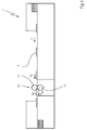
- Fig. 1 shows a Faltschachtelklebemaschine 1 with a rotary embossing device 10 according to the invention.
- Faltschachtelzuitese 2 are transported by a feeder in the transport direction T through the Faltschachtelklebemaschine 1 and by the rotary embossing device 10 to a boom.
- the rotary embossing device 10 has a male part 11 and a die 12 for introducing embossments into the folding box blanks 2.
- the folded box blanks 2 are transported with a board pitch A, also referred to as a section length, at the speed vF.
- the male part 11 has the speed vP.
- the die 12 has the speed vM.
- the speeds of matrix vM, male vP and folding carton vF have the same amount so that there is no relative movement between tools 11, 12 and folding carton blank 2 and thus markings of the folding carton blank are avoided.
- the male part 11 and die 12 must be synchronized relative to each other in terms of their speed.
- male and female mold 11 12 must be synchronized relative to each other with respect to their angular position, ie it must be ensured that the punch of the male part 11 can dive into holes of the die 12.
- Do Patrize 11 and die 12 each have their own embossing tool drive so the synchronization is preferably electronically. If the male part 11 and the female part 12 are driven by a common embossing tool drive, the synchronization takes place mechanically, for example by coupling the male part 11 and the female part 12.
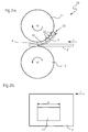
- Fig. 2a shows a detailed view of the rotary embossing device 10 in a sectional view.
- the rotary embossing device 10 has a male part 11 and a female part 12, both of which rotate as indicated by arrows. Between the male part 11 and female part 12 is a folding box blank 2, which is transported in the transport direction T. Fixedly connected to the male part 11 is an embossing segment 31. Further embossing segments 32 are designed to be interchangeable and can be detachably fastened to the male part 11. The embossing segments 30 are raised in relation to the lateral surface of the embossing roller of the male part 11. D. h.
- the embossing radius of the male part 11 is greater in the regions of the embossing segments 30 than the radius in those regions of the male part 11 which are not with Embossed segments 30 are provided.
- a film 110 is stretched (see Fig. 2c ), which is provided with stamping 111.
- the embossing segments 30 extend over the circumference of a partial circle X.
- the extent X of the embossing segments 30 is matched to the length X of the embossing to be produced.
- the extension of the embossing segment 30 is matched by combining the fixed embossing segment 31 with a corresponding number of replaceable embossing segments 32 and also has the length X. This achieves and as in Fig. 2a illustrated that the male part 11 rolls on the folding box blank 2 only during the embossing process in the region of the embossing segment 30 and causes its embossing. Before and after the embossing process, the male part 11 is not in contact with the folding box blank 2.
- the male part 11 can be accelerated or decelerated, so as to be able to synchronize the stamped embossing segment 30 relative to the position of an imprinted area 21 of a folding carton blank 2, ie to be able to align.
Description
Die Erfindung betrifft eine Rotationsprägeeinrichtung gemäß dem Oberbegriff von Anspruch 1 und eine Faltschachtelklebemaschine nach Anspruch 7.The invention relates to a rotary embossing device according to the preamble of claim 1 and a folding box gluing machine according to claim 7.
Faltschachteln sind Verpackungen aus Karton oder Wellpappe, in geringem Umfang auch aus Kunststoff, die je nach Konstruktion während des Faltprozesses an einer oder mehreren Stellen beleimt werden. Sie werden in der Regel aus einem Zuschnitt produziert. Die Zuschnitte werden üblicherweise auf einer Bogenstanze ausgestanzt. Der Zuschnitt muss mindestens an einer Kante verklebt werden. Die gefalteten Schachteln kommen im flachliegenden Zustand aus der Faltschachtel-Klebemaschine. Das Aufstellen und Befüllen der Schachtel kann maschinell oder auch manuell erfolgen.Folding cartons are cardboard or corrugated board packaging, and to a lesser extent plastic, which are glued at one or more points during the folding process, depending on the design. They are usually produced from a blank. The blanks are usually punched out on a sheet punch. The blank must be glued at least at one edge. The folded boxes come out of the carton gluer in the flat state. The placement and filling of the box can be done by machine or manually.
Neben den Faltungen, die zur Herstellung der Faltschachteln erforderlich sind, werden als Vorbereitung für den anschließenden Produktionsschritt auch weitere Rilllinien in der Faltschachtel-Klebemaschine vorgebrochen (vorgefaltet). Dadurch werden das Aufstellen der Schachtel und das spätere Befüllen erleichtert.In addition to the folds required to produce the cartons, further creasing lines in the carton gluer are pre-broken (prefolded) to prepare for the subsequent production step. This facilitates the installation of the box and the subsequent filling.
Dienen die Faltschachteln zur Verpackung von Arzneimitteln, so ist es gesetzlich vorgeschrieben, die Bezeichnung des Arzneimittels in Blindenschrift (so genannte Braille-Schrift) auf die Faltschachtel aufzubringen (bspw. durch Prägen).If the cartons are used to package medicines, it is legally required to apply the name of the medicament in braille (so-called Braille) to the carton (eg by embossing).
Nach dem Stand der Technik erfolgt die Prägung der Blindenschrift entweder während des Stanzprozesses in der Bogenstanze bei der Herstellung der Zuschnitte. Dies ist jedoch aufwendig, da ein Stanzbogen etliche Nutzen, d. h. Zuschnitte enthält und für jeden Nutzen ein Werkzeugpaar bestehend aus Matrize und Patrize bereitgestellt werden muss. Oder es kommen Rotationsprägeeinrichtungen mit zwei rotierenden Prägewerkzeugen zum Einsatz, welche beispielsweise Teil einer Faltschachtelklebemaschine sein können. Bekannter weise verfügen derartige Rotationsprägeeinrichtungen über einen gemeinsamen Antrieb für beide Rotationswerkzeuge. Um die Prägung an der richtigen Position auf den Faltschachtelzuschnitt aufbringen zu können, müssen die Rotationswerkzeuge relativ zum Faltschachtelzuschnitt synchronisiert werden. Insbesondere beim Einbringen einer Blindenschrift in den Faltschachtelzuschnitt muss die Synchronisierung sehr genau erfolgen. Aufgrund des Massenträgheitsmoments von Matrize, Patrize und Rotationsantrieb ist die erforderliche Genauigkeit der Synchronisierung nur schwer bis gar nicht zu erreichen. Weiter nachteilig ist, dass Rotationsprägeeinrichtungen zur besseren Synchronisierung häufig im Start- / Stopp-Betrieb gefahren werden. D. h. die Rotationsprägewerkzeuge werden zur Synchronisierung angehalten und nachfolgend wieder neu beschleunigt. Dadurch wird die Produktionsleistung der Rotationsprägeeinrichtung stark eingeschränkt. Weiter wird dir Produktionsleistung dadurch eingeschränkt, dass keine Anpassung der Rotationsprägeeinrichtung an die Größe des zu bearbeitenden Produktes möglich ist.According to the prior art, the embossing of braille is carried out either during the punching process in the sheet punch in the production of blanks. However, this is expensive because a punching sheet several benefits, ie blanks contains and for each benefit a pair of tools consisting of die and male must be provided. Or there are rotary embossing devices with two rotating embossing tools are used, which may for example be part of a Faltschachtelklebemaschine. As known, such rotary embossing devices have a common drive for both rotary tools. In order to apply the embossing in the correct position on the Faltschachtelzuschnitt, the rotary tools must be synchronized relative to Faltschachtelzuschnitt. In particular, when introducing a Braille in the carton blank, the synchronization must be done very accurately. Due to the moment of inertia of die, male and rotary drive the required accuracy of synchronization is difficult or impossible to achieve. Another disadvantage is that rotary embossing devices for better synchronization are often driven in start / stop operation. Ie. the rotary embossing tools are stopped for synchronization and subsequently accelerated again. As a result, the production capacity of the rotary embossing device is severely limited. Next you production is limited by the fact that no adjustment of the rotary embossing device to the size of the product to be processed is possible.
Die
Die
Aufgabe der vorliegenden Erfindung ist es, eine Rotationsprägeeinrichtung zu schaffen, welche die Nachteile des Standes der Technik überwindet und bei gleichzeitig hoher Prägequalität eine hohe Ausbringung ermöglicht.The object of the present invention is to provide a rotary embossing device which overcomes the disadvantages of the prior art and enables high output while maintaining high embossing quality.
Gelöst wird diese Aufgabe durch eine Rotationsprägeeinrichtung mit den kennzeichnenden Merkmalen von Anspruch 1.This object is achieved by a rotary embossing device with the characterizing features of claim 1.
Die erfindungsgemäße Rotationsprägeeinrichtung besitzt zwei rotierende Prägewerkzeuge, angetrieben durch mindestens einen Prägewerkzeugantrieb, zum Einbringen von Prägungen, insbesondere Blindenschrift, in Bedruckstoffe, insbesondere Faltschachtelzuschnitte. Die Prägewerkzeuge werden durch eine mit Stempeln versehene Patrize und eine Matrize gebildet. Die Matrize dient als Gegenform und ist vorteilhafter weise produktneutral und besitzt ein gleichmäßiges Lochmuster. Die Patrize ist als Prägewalze und die Matrize ebenfalls als Walze ausgebildet. Auf der Prägewalze ist ein Prägesegment angebracht, welches erhaben gegenüber der Mantelfläche der Prägewalze ist. Die Länge des Prägesegments - in Umfangsrichtung der Prägewalze betrachtet - entspricht der Erstreckung - in Transportrichtung betrachtet - einer mit einer Prägung zu versehenden Fläche eines Bedruckstoffes. Das Prägesegment ist mit Prägestempeln versehen und bildet während des Prägevorgangs eine Prägung der gewünschten Länge. Während des Prägevorgangs entspricht der Abstand zwischen der Oberfläche des Prägesegments und der Mantelfläche der Matrizenwalze in etwa der Dicke des zu bearbeitenden Bedruckstoffs. Der Abstand der Mantelfläche der Patrizenwalze und der Matrizenwalze, während nicht geprägt wird, ist größer als die Dicke des zu bearbeitenden Bedruckstoffs. Dadurch wird ermöglicht, dass durch beschleunigen und / oder abbremsen der Prägewerkzeuge eine Synchronisation der Prägewerkzeuge relativ zum nachfolgenden Bedruckstoff, d. h. eine Positionierung des Prägesegments relativ zur Position einer mit einer Prägung zu versehenden Fläche auf einen nachfolgenden Bedruckstoff, stattfinden kann.The rotary embossing device according to the invention has two rotating embossing tools, driven by at least one embossing tool drive, for introducing Embossings, in particular Braille, in printing materials, in particular folding carton blanks. The embossing tools are formed by a stamped male and a die. The template serves as a counter-mold and is advantageously product-neutral and has a uniform hole pattern. The male part is designed as an embossing roller and the die also as a roller. On the embossing roller, a embossing segment is mounted, which is raised with respect to the lateral surface of the embossing roller. The length of the embossing segment - viewed in the circumferential direction of the embossing roll - corresponds to the extent - viewed in the direction of transport - a to be provided with an embossed surface of a printing substrate. The embossing segment is provided with embossing stamps and forms an embossing of the desired length during the embossing process. During the embossing process, the distance between the surface of the embossing segment and the lateral surface of the die roller corresponds approximately to the thickness of the substrate to be processed. The distance of the lateral surface of the male and the die roller, while not being embossed, is greater than the thickness of the substrate to be processed. This makes it possible that, by accelerating and / or braking the embossing tools, synchronization of the embossing tools relative to the following printing material, ie positioning of the embossing segment relative to the position of an area to be embossed onto a subsequent printing material, can take place.
In einer vorteilhaften Ausführungsform der erfindungsgemäßen Rotationsprägeeinrichtung sind Matrize und / oder Patrize einfach austauschbar. Dadurch kann die Rotationsprägeeinrichtung beispielsweise mit einer Patrize bestückt werden, welche ein Prägesegment besitzt, dessen Länge der Erstreckung einer mit einer Prägung zu versehenden Fläche eines Bedruckstoffes entspricht.In an advantageous embodiment of the rotary embossing device according to the invention, die and / or male are easily interchangeable. As a result, the rotary embossing device can be equipped, for example, with a male part which has a embossing segment whose length corresponds to the extent of an area of a printing material to be embossed.
In einer vorteilhaften Ausführungsform der Rotationsprägeeinrichtung sind Matrize und Patrize quer verschieblich und arretierbar auf einer Matrizenwelle bzw. Patrizenwelle angebracht. Dies ermöglicht eine freie Positionierung der Prägung über die Breite eines Bedruckstoffs, d. h. quer zur Transportrichtung des Bedruckstoffs.In an advantageous embodiment of the rotary embossing device die and male are mounted transversely displaceable and lockable on a die shaft or male shaft. This allows a free positioning of the embossing across the width of a printing material, ie transversely to the transport direction of the printing substrate.
In einer besonders vorteilhaften Weiterbildung der Rotationsprägeeinrichtung besteht das Prägesegment aus einem fest mit der Prägewalze verbundenen Segment und mindestens einem weiteren an der Prägewalze lösbar befestigbaren Segment. Das lösbare Segment hat vorteilhafterweise kleinere Ausmaße als das fest mit der Prägewalze verbundene Segment. Dadurch wird es ermöglicht, dass die Erstreckung einer mit einer Prägung zu versehenden Fläche eines Bedruckstoffs durch die Länge des festen Prägesegments und den Längen einer entsprechenden Anzahl an lösbaren Segmenten gebildet wird. Die lösbaren Prägesegmente können beispielsweise mit einem Schwalbenschwanzprofil versehen sein und parallel zur Achse der Patrize auf diese aufgeschoben werden und zur Arretierung verklemmt werden.In a particularly advantageous development of the rotary embossing device, the embossing segment consists of a segment fixedly connected to the embossing roller and at least one further segment releasably securable to the embossing roller. The detachable segment advantageously has smaller dimensions than the segment fixedly connected to the embossing roller. This makes it possible for the extent of a surface of a printing material to be embossed to be formed by the length of the fixed embossing segment and the lengths of a corresponding number of detachable segments. The detachable embossed segments can be provided, for example, with a dovetail profile and be pushed parallel to the axis of the male on this and jammed for locking.
In einer vorteilhaften Ausführungsform der Rotationsprägeeinrichtung ist auf das einteilige oder mehrteilige Prägesegment eine mit Prägestempeln versehene Folie aufspannbar. Eine solche Folie ist einfach und kostengünstig herzustellen, erlaubt eine schnelle Montage und einer einfache Austauschbarkeit. Alternativ können die Prägesegmente auch direkt mit Prägestempeln versehen sein.In an advantageous embodiment of the rotary embossing device, a foil provided with embossing stamps can be clamped on the one-part or multi-part embossing segment. Such a film is simple and inexpensive to manufacture, allows a quick installation and easy replacement. Alternatively, the embossing segments can also be provided directly with stamping dies.
Hinsichtlich weiterer vorteilhafter Ausgestaltungen der Erfindung wird auf die Unteransprüche sowie die Beschreibung eines Ausführungsbeispiels unter Bezugnahme auf die beiliegenden Zeichnungen verwiesen.With regard to further advantageous embodiments of the invention, reference is made to the dependent claims and the description of an embodiment with reference to the accompanying drawings.
Die Erfindung soll anhand eines Ausführungsbeispiels noch näher erläutert werden. Es zeigen in schematischer Darstellung:
- Fig. 1
- den Aufbau einer Faltschachtelklebemaschine mit erfindungsgemäßer Rotationsprägeeinrichtung
- Fig. 2a
- eine Detailansicht der Rotationsprägeeinrichtung mit Prägesegmenten an der Patrize
- Fig. 2b
- einen Bedruckstoff mit der Position der Prägung
- Fig. 2c
- eine Detailansicht der Patrize
- Fig. 1
- the structure of a Faltschachtelklebemaschine with inventive rotation embossing device
- Fig. 2a
- a detailed view of the rotary embossing device with embossed segments on the male
- Fig. 2b
- a substrate with the position of the embossing
- Fig. 2c
- a detail view of the patrix
In der Berührungslinie von Patrize 11 und Faltschachtelzuschnitt 2 während des Prägevorgangs besitzt die Patrize 11 die Geschwindigkeit vP. In der Berührungslinie von Matrize 12 mit Faltschachtelzuschnitt 2 während des Prägevorgangs besitzt die Matrize 12 die Geschwindigkeit vM. Während des Prägevorgangs haben die Geschwindigkeiten von Matrize vM, Patrize vP und Faltschachtelzuschnitt vF denselben Betrag, so dass es zu keinen Relativbewegungen zwischen Werkzeugen 11, 12 und Faltschachtelzuschnitt 2 kommt und damit Markierungen des Faltschachtelzuschnitts vermieden werden. Dazu müssen Patrize 11 und Matrize 12 relativ zueinander bezüglich ihrer Geschwindigkeit synchronisiert sein. Weiter müssen Patrize 11 und Matrize 12 relativ zueinander bezüglich ihrer Winkelposition synchronisiert sein, d.h. es muss sichergestellt sein, dass die Stempel der Patrize 11 in Löcher der Matrize 12 eintauchen können. Besitzen Patrize 11 und Matrize 12 jeweils einen eigenen Prägewerkzeugantrieb so erfolgt die Synchronisation bevorzugt elektronisch. Werden Patrize 11 und Matrize 12 durch einen gemeinsamen Prägewerkzeugantrieb angetrieben, so erfolgt die Synchronisation mechanisch, beispielsweise durch Kopplung von Patrize 11 und Matrize 12.
In the contact line of
Die Prägesegmente 30 erstrecken sich über den Umfang eines Teilkreises X. Die Erstreckung X der Prägesegmente 30 ist dabei auf die Länge X der zu erzeugenden Prägung abgestimmt. Wie in
- 11
- Faltschachtelklebemaschinegluer
- 22
- Faltschachtelzuschnittfolding box
- 1010
- RotationsprägeeinrichtungRotary embosser
- 1111
- Patrizepunch
- 1212
- Matrizedie
- 1313
- PatrizenwellePatrizenwelle
- 1414
- MatrizenwelleMatrizenwelle
- 2121
- mit einer Prägung zu versehende Flächearea to be imprinted
- 3030
- Prägesegmentcoin segment
- 3131
- festes Prägesegmentfirm embossing segment
- 3232
- austauschbares Prägesegmentexchangeable embossing segment
- 110110
- Foliefoil
- 111111
- Stempelstamp
- vPvP
- Geschwindigkeit PatrizeSpeed male
- vMvM
- Geschwindigkeit MatrizeSpeed die
- vFvF
- Geschwindigkeit FaltschachtelzuschnittSpeed folding carton blank
- AA
- Abstand zweiter FaltschachtelzuschnitteDistance between second folding carton blanks
- TT
- Transportrichtungtransport direction
- XX
- Länge der zu erzeugenden PrägungLength of the embossing to be produced
- BB
- Berührungslinie Patrize - FaltschachtelzuschnittTouch line male - folding carton blank
- bb
- Bewegung der PatrizeMovement of the patrix
Claims (8)
- A rotary embossing device (10) including two rotating cylindrical embossing tools (11, 12), embodied as a male tool (11) and a female tool (12) for introducing embossments, in particular braille characters, into a printing material (2), in particular a folding box blank, wherein the male tool (11) is embodied as an embossing roller having an embossing die (111) and the female tool (12) is likewise embodied as a roller,
wherein an embossing segment (30) is attached to the embossing roller, the embossing segment being raised relative to the circumferential surface of the embossing roller and having a length (X) in the circumferential direction of the embossing roller that corresponds to the extension of a printing material (2) surface (21) to be embossed in the transport direction (T),
and wherein the embossing segment (30) is provided with embossing dies (111), characterized in
that during the embossing process, the distance between the surface of the embossing segment and the circumferential surface of the female tool roller approximately corresponds to the thickness of the printing material (2) to be processed,
that when no embossing takes place, the distance between the circumferential surface of the female tool roller and the circumferential surface of the embossing roller is greater than the thickness of the printing material to be processed,
and that the female tool (12) is embodied as an all-purpose counter-form. - Rotary embossing device according to Claim 1,
characterized in
that the male tool (11) can be accelerated or decelerated to be able to synchronize the embossing segment (30) provided with embossing dies (111) relative to the position of a surface (21) of a printing material (2) to be provided with an embossment and that the male tool (11) does not contact the printing material (2) during the process. - Rotary embossing device according to Claim 1,
characterized in
that the female tool (12) and/or the male tool (11) are easily exchangeable. - Rotary embossing device according to Claim 1,
characterized in
that the female tool (12) and the male tool (11) are arranged on a female tool shaft (14) and a male tool shaft (13), respectively, in a way to be transversely movable. - Rotary embossing device according to Claim 1, 2, or 4,
characterized in
that the embossing segment (30) consists of a segment (31) that is firmly connected to the embossing roller and of at least one further segment (32) that is releasably fixable to the embossing roller. - Rotary embossing device according to one of Claims 1, 2, 4, or 5,
characterized in
that a foil (110) provided with embossing dies (111) is mountable onto the embossing segment (30). - Rotary embossing device according to one of Claims 1, 2, 4, or 5,
characterized in
that the embossing dies (111) are firmly connected to the embossing segment (30). - Folding-box gluing machine (1) including a rotary embossing device (10) according to one of claims 1 to 7.
Applications Claiming Priority (1)
| Application Number | Priority Date | Filing Date | Title |
|---|---|---|---|
| DE102007060613A DE102007060613A1 (en) | 2007-12-13 | 2007-12-13 | Rotary embosser |
Publications (2)
| Publication Number | Publication Date |
|---|---|
| EP2075115A1 EP2075115A1 (en) | 2009-07-01 |
| EP2075115B1 true EP2075115B1 (en) | 2013-04-17 |
Family
ID=40602681
Family Applications (1)
| Application Number | Title | Priority Date | Filing Date |
|---|---|---|---|
| EP08105870.3A Active EP2075115B1 (en) | 2007-12-13 | 2008-11-26 | Rotation stamping device |
Country Status (2)
| Country | Link |
|---|---|
| EP (1) | EP2075115B1 (en) |
| DE (1) | DE102007060613A1 (en) |
Cited By (1)
| Publication number | Priority date | Publication date | Assignee | Title |
|---|---|---|---|---|
| WO2023230381A1 (en) * | 2022-05-27 | 2023-11-30 | Horowitz Joshua | Braille embossing device using interchangeable braille letters on a wheel for labeling applications |
Families Citing this family (5)
| Publication number | Priority date | Publication date | Assignee | Title |
|---|---|---|---|---|
| GB0817509D0 (en) * | 2008-09-24 | 2008-10-29 | Chesapeake Plc | Rotary embossing |
| DE102011113632A1 (en) | 2011-09-16 | 2012-06-06 | Heidelberger Druckmaschinen Aktiengesellschaft | Apparatus for rotary embossing of sheet/web shaped workpiece e.g. printed sheet for Braille formation, has control device to control operation of actuator connected to stamping die of embossing tool, based on variable embossing pattern |
| DE102012019372A1 (en) | 2011-10-26 | 2013-05-02 | Heidelberger Druckmaschinen Ag | Method for embossing products with a rotary embossing device |
| DE102013012437A1 (en) * | 2013-07-29 | 2015-01-29 | Focke & Co. (Gmbh & Co. Kg) | Method and device for producing blanks for collars of packages for cigarettes |
| CN104859289A (en) * | 2015-04-30 | 2015-08-26 | 句容市鼎盛纸箱包装有限公司 | Packaging box three-color slotting anti-fake printing machine |
Family Cites Families (19)
| Publication number | Priority date | Publication date | Assignee | Title |
|---|---|---|---|---|
| US1060387A (en) * | 1912-09-24 | 1913-04-29 | William B Wait | Marginal holding device. |
| US2074966A (en) * | 1935-03-11 | 1937-03-23 | Andrews Steel Company | Apparatus for manufacturing surfacing units |
| FR1596950A (en) * | 1968-12-18 | 1970-06-22 | ||
| US3598042A (en) * | 1969-03-17 | 1971-08-10 | Harry S Boyd | Braille printing system |
| US3921524A (en) * | 1974-09-19 | 1975-11-25 | Pitney Bowes Inc | Rotary printer with removable printing die |
| GB1598183A (en) | 1977-08-05 | 1981-09-16 | Chambon Ltd | Rotary embossing machine having intermeshing adjustable dies |
| GB2255317A (en) * | 1991-04-11 | 1992-11-04 | Profoil Systems Limited | Foil blocking dies |
| DE4125996C1 (en) * | 1991-08-06 | 1993-03-04 | Hans-Peter 5620 Velbert De Steinforth | Heat stamping roller - has hollow drum member with internal heat system, and drum mantle with stamping profile etc. |
| US5505125A (en) * | 1993-10-04 | 1996-04-09 | Western Printing Machinery Company | Method and apparatus for forming a rotary embossing die with a support plate |
| DE4345128A1 (en) * | 1993-12-30 | 1995-07-06 | Detroit Holding Ltd | Embossing device |
| DE19612314C1 (en) * | 1996-03-28 | 1997-10-16 | Koenig & Bauer Albert Ag | Embossing cylinder |
| US6387201B1 (en) * | 1999-05-14 | 2002-05-14 | Best Cutting Die Company | Rotary hot foil stamping machine |
| GB2346589B (en) * | 2000-05-16 | 2001-01-31 | Sil Die Ltd | Construction of dies |
| DE10040683C2 (en) * | 2000-08-19 | 2002-06-27 | Hinderer & Muehlich Kg | Method for positioning a male on a counter-pressure roller of an embossing station |
| DE10156430A1 (en) * | 2001-11-16 | 2003-05-28 | Winkler & Duennebier Ag | Embossing die pair comprises a male mold and female mold provided with positioning devices that are brought into alignment by a separate positioning element |
| JP2005509544A (en) * | 2001-11-23 | 2005-04-14 | グルズ・アンド・マーストラン・アクティーゼルスカブ | Device for 3D structure processing on substrates |
| NL1024915C2 (en) | 2003-12-01 | 2005-06-06 | Jean Henry Robert Madern | Device for making a cut, groove and the like, comprising a plate-shaped system. |
| DE10306210A1 (en) | 2003-02-13 | 2004-08-26 | Hermann Hötten Maschinenbau GmbH | Method and device for double-sided transverse creasing of continuous webs |
| US7096709B2 (en) * | 2004-05-21 | 2006-08-29 | Universal Engraving, Inc. | Graphic arts die and support plate assembly |
-
2007
- 2007-12-13 DE DE102007060613A patent/DE102007060613A1/en not_active Withdrawn
-
2008
- 2008-11-26 EP EP08105870.3A patent/EP2075115B1/en active Active
Cited By (1)
| Publication number | Priority date | Publication date | Assignee | Title |
|---|---|---|---|---|
| WO2023230381A1 (en) * | 2022-05-27 | 2023-11-30 | Horowitz Joshua | Braille embossing device using interchangeable braille letters on a wheel for labeling applications |
Also Published As
| Publication number | Publication date |
|---|---|
| EP2075115A1 (en) | 2009-07-01 |
| DE102007060613A1 (en) | 2009-06-18 |
Similar Documents
| Publication | Publication Date | Title |
|---|---|---|
| EP2422971B1 (en) | Tool holding device | |
| EP1920910B1 (en) | Device and method for inline control of Braille writing for manufacturing folding boxes | |
| EP0187323B1 (en) | Method and device for the production of package blanks | |
| EP1837136B1 (en) | Device and method for cutting out flat material blanks in sheets of flat material | |
| EP2075115B1 (en) | Rotation stamping device | |
| EP2070721B1 (en) | Rotation embossing device and box folding and glueing machine | |
| EP2422993B1 (en) | Braille casing | |
| EP2058115B1 (en) | Rotation stamping device | |
| EP2746007B1 (en) | Manufacturing system and process with flat bed and a rotary die unit | |
| DE102012019372A1 (en) | Method for embossing products with a rotary embossing device | |
| EP2036712B1 (en) | Rotation embossing device and embossing method | |
| DE102007044827A1 (en) | Folded box gluing machine, has conveying belts arranged to deliver blanks through orienting station and pre-breaker station, and embossing mechanism with dies arranged between two stations so as to emboss blanks | |
| WO2014009005A1 (en) | Device for producing pre-cuts, particularly for cigarette packets | |
| EP3027516B1 (en) | Methods and device for producing blanks for collars of packages for cigarettes | |
| EP2047973A2 (en) | Rotation stamping device | |
| EP2759397B1 (en) | Rotation stamping device with tensioning system and angle adjustment | |
| EP2689924B1 (en) | Tool holding device | |
| EP2743072B1 (en) | Creasing method | |
| EP1974897B1 (en) | Device for embossing a number of crease lines into a layer of material | |
| DE102016011960B4 (en) | central cylinder | |
| DE102014004756A1 (en) | Faltschachtelmaschine with foil stamping device |
Legal Events
| Date | Code | Title | Description |
|---|---|---|---|
| PUAI | Public reference made under article 153(3) epc to a published international application that has entered the european phase |
Free format text: ORIGINAL CODE: 0009012 |
|
| AK | Designated contracting states |
Kind code of ref document: A1 Designated state(s): AT BE BG CH CY CZ DE DK EE ES FI FR GB GR HR HU IE IS IT LI LT LU LV MC MT NL NO PL PT RO SE SI SK TR |
|
| AX | Request for extension of the european patent |
Extension state: AL BA MK RS |
|
| 17P | Request for examination filed |
Effective date: 20100104 |
|
| 17Q | First examination report despatched |
Effective date: 20100129 |
|
| AKX | Designation fees paid |
Designated state(s): AT BE BG CH CY CZ DE DK EE ES FI FR GB GR HR HU IE IS IT LI LT LU LV MC MT NL NO PL PT RO SE SI SK TR |
|
| GRAP | Despatch of communication of intention to grant a patent |
Free format text: ORIGINAL CODE: EPIDOSNIGR1 |
|
| GRAS | Grant fee paid |
Free format text: ORIGINAL CODE: EPIDOSNIGR3 |
|
| GRAA | (expected) grant |
Free format text: ORIGINAL CODE: 0009210 |
|
| AK | Designated contracting states |
Kind code of ref document: B1 Designated state(s): AT BE BG CH CY CZ DE DK EE ES FI FR GB GR HR HU IE IS IT LI LT LU LV MC MT NL NO PL PT RO SE SI SK TR |
|
| REG | Reference to a national code |
Ref country code: GB Ref legal event code: FG4D Free format text: NOT ENGLISH |
|
| REG | Reference to a national code |
Ref country code: CH Ref legal event code: EP |
|
| REG | Reference to a national code |
Ref country code: IE Ref legal event code: FG4D Free format text: LANGUAGE OF EP DOCUMENT: GERMAN |
|
| REG | Reference to a national code |
Ref country code: AT Ref legal event code: REF Ref document number: 606991 Country of ref document: AT Kind code of ref document: T Effective date: 20130515 |
|
| REG | Reference to a national code |
Ref country code: DE Ref legal event code: R096 Ref document number: 502008009722 Country of ref document: DE Effective date: 20130613 |
|
| REG | Reference to a national code |
Ref country code: LT Ref legal event code: MG4D |
|
| REG | Reference to a national code |
Ref country code: NL Ref legal event code: VDEP Effective date: 20130417 |
|
| PG25 | Lapsed in a contracting state [announced via postgrant information from national office to epo] |
Ref country code: LT Free format text: LAPSE BECAUSE OF FAILURE TO SUBMIT A TRANSLATION OF THE DESCRIPTION OR TO PAY THE FEE WITHIN THE PRESCRIBED TIME-LIMIT Effective date: 20130417 Ref country code: GR Free format text: LAPSE BECAUSE OF FAILURE TO SUBMIT A TRANSLATION OF THE DESCRIPTION OR TO PAY THE FEE WITHIN THE PRESCRIBED TIME-LIMIT Effective date: 20130718 Ref country code: ES Free format text: LAPSE BECAUSE OF FAILURE TO SUBMIT A TRANSLATION OF THE DESCRIPTION OR TO PAY THE FEE WITHIN THE PRESCRIBED TIME-LIMIT Effective date: 20130728 Ref country code: FI Free format text: LAPSE BECAUSE OF FAILURE TO SUBMIT A TRANSLATION OF THE DESCRIPTION OR TO PAY THE FEE WITHIN THE PRESCRIBED TIME-LIMIT Effective date: 20130417 Ref country code: SI Free format text: LAPSE BECAUSE OF FAILURE TO SUBMIT A TRANSLATION OF THE DESCRIPTION OR TO PAY THE FEE WITHIN THE PRESCRIBED TIME-LIMIT Effective date: 20130417 Ref country code: IS Free format text: LAPSE BECAUSE OF FAILURE TO SUBMIT A TRANSLATION OF THE DESCRIPTION OR TO PAY THE FEE WITHIN THE PRESCRIBED TIME-LIMIT Effective date: 20130817 Ref country code: SE Free format text: LAPSE BECAUSE OF FAILURE TO SUBMIT A TRANSLATION OF THE DESCRIPTION OR TO PAY THE FEE WITHIN THE PRESCRIBED TIME-LIMIT Effective date: 20130417 Ref country code: PT Free format text: LAPSE BECAUSE OF FAILURE TO SUBMIT A TRANSLATION OF THE DESCRIPTION OR TO PAY THE FEE WITHIN THE PRESCRIBED TIME-LIMIT Effective date: 20130819 Ref country code: NO Free format text: LAPSE BECAUSE OF FAILURE TO SUBMIT A TRANSLATION OF THE DESCRIPTION OR TO PAY THE FEE WITHIN THE PRESCRIBED TIME-LIMIT Effective date: 20130717 |
|
| PG25 | Lapsed in a contracting state [announced via postgrant information from national office to epo] |
Ref country code: LV Free format text: LAPSE BECAUSE OF FAILURE TO SUBMIT A TRANSLATION OF THE DESCRIPTION OR TO PAY THE FEE WITHIN THE PRESCRIBED TIME-LIMIT Effective date: 20130417 Ref country code: CY Free format text: LAPSE BECAUSE OF FAILURE TO SUBMIT A TRANSLATION OF THE DESCRIPTION OR TO PAY THE FEE WITHIN THE PRESCRIBED TIME-LIMIT Effective date: 20130417 Ref country code: BG Free format text: LAPSE BECAUSE OF FAILURE TO SUBMIT A TRANSLATION OF THE DESCRIPTION OR TO PAY THE FEE WITHIN THE PRESCRIBED TIME-LIMIT Effective date: 20130717 Ref country code: PL Free format text: LAPSE BECAUSE OF FAILURE TO SUBMIT A TRANSLATION OF THE DESCRIPTION OR TO PAY THE FEE WITHIN THE PRESCRIBED TIME-LIMIT Effective date: 20130417 Ref country code: HR Free format text: LAPSE BECAUSE OF FAILURE TO SUBMIT A TRANSLATION OF THE DESCRIPTION OR TO PAY THE FEE WITHIN THE PRESCRIBED TIME-LIMIT Effective date: 20130417 |
|
| PG25 | Lapsed in a contracting state [announced via postgrant information from national office to epo] |
Ref country code: CZ Free format text: LAPSE BECAUSE OF FAILURE TO SUBMIT A TRANSLATION OF THE DESCRIPTION OR TO PAY THE FEE WITHIN THE PRESCRIBED TIME-LIMIT Effective date: 20130417 Ref country code: DK Free format text: LAPSE BECAUSE OF FAILURE TO SUBMIT A TRANSLATION OF THE DESCRIPTION OR TO PAY THE FEE WITHIN THE PRESCRIBED TIME-LIMIT Effective date: 20130417 Ref country code: EE Free format text: LAPSE BECAUSE OF FAILURE TO SUBMIT A TRANSLATION OF THE DESCRIPTION OR TO PAY THE FEE WITHIN THE PRESCRIBED TIME-LIMIT Effective date: 20130417 Ref country code: SK Free format text: LAPSE BECAUSE OF FAILURE TO SUBMIT A TRANSLATION OF THE DESCRIPTION OR TO PAY THE FEE WITHIN THE PRESCRIBED TIME-LIMIT Effective date: 20130417 |
|
| PLBE | No opposition filed within time limit |
Free format text: ORIGINAL CODE: 0009261 |
|
| STAA | Information on the status of an ep patent application or granted ep patent |
Free format text: STATUS: NO OPPOSITION FILED WITHIN TIME LIMIT |
|
| PG25 | Lapsed in a contracting state [announced via postgrant information from national office to epo] |
Ref country code: IT Free format text: LAPSE BECAUSE OF FAILURE TO SUBMIT A TRANSLATION OF THE DESCRIPTION OR TO PAY THE FEE WITHIN THE PRESCRIBED TIME-LIMIT Effective date: 20130417 Ref country code: NL Free format text: LAPSE BECAUSE OF FAILURE TO SUBMIT A TRANSLATION OF THE DESCRIPTION OR TO PAY THE FEE WITHIN THE PRESCRIBED TIME-LIMIT Effective date: 20130417 Ref country code: RO Free format text: LAPSE BECAUSE OF FAILURE TO SUBMIT A TRANSLATION OF THE DESCRIPTION OR TO PAY THE FEE WITHIN THE PRESCRIBED TIME-LIMIT Effective date: 20130417 |
|
| 26N | No opposition filed |
Effective date: 20140120 |
|
| REG | Reference to a national code |
Ref country code: DE Ref legal event code: R097 Ref document number: 502008009722 Country of ref document: DE Effective date: 20140120 |
|
| BERE | Be: lapsed |
Owner name: HEIDELBERGER DRUCKMASCHINEN A.G. Effective date: 20131130 |
|
| GBPC | Gb: european patent ceased through non-payment of renewal fee |
Effective date: 20131126 |
|
| PG25 | Lapsed in a contracting state [announced via postgrant information from national office to epo] |
Ref country code: MC Free format text: LAPSE BECAUSE OF FAILURE TO SUBMIT A TRANSLATION OF THE DESCRIPTION OR TO PAY THE FEE WITHIN THE PRESCRIBED TIME-LIMIT Effective date: 20130417 |
|
| REG | Reference to a national code |
Ref country code: FR Ref legal event code: ST Effective date: 20140731 |
|
| REG | Reference to a national code |
Ref country code: IE Ref legal event code: MM4A |
|
| PG25 | Lapsed in a contracting state [announced via postgrant information from national office to epo] |
Ref country code: BE Free format text: LAPSE BECAUSE OF NON-PAYMENT OF DUE FEES Effective date: 20131130 |
|
| PG25 | Lapsed in a contracting state [announced via postgrant information from national office to epo] |
Ref country code: IE Free format text: LAPSE BECAUSE OF NON-PAYMENT OF DUE FEES Effective date: 20131126 |
|
| PG25 | Lapsed in a contracting state [announced via postgrant information from national office to epo] |
Ref country code: GB Free format text: LAPSE BECAUSE OF NON-PAYMENT OF DUE FEES Effective date: 20131126 Ref country code: FR Free format text: LAPSE BECAUSE OF NON-PAYMENT OF DUE FEES Effective date: 20131202 |
|
| REG | Reference to a national code |
Ref country code: AT Ref legal event code: MM01 Ref document number: 606991 Country of ref document: AT Kind code of ref document: T Effective date: 20131126 |
|
| PG25 | Lapsed in a contracting state [announced via postgrant information from national office to epo] |
Ref country code: AT Free format text: LAPSE BECAUSE OF NON-PAYMENT OF DUE FEES Effective date: 20131126 |
|
| REG | Reference to a national code |
Ref country code: DE Ref legal event code: R081 Ref document number: 502008009722 Country of ref document: DE Owner name: MASTERWORK MACHINERY CO., LTD., CN Free format text: FORMER OWNER: HEIDELBERGER DRUCKMASCHINEN AKTIENGESELLSCHAFT, 69115 HEIDELBERG, DE Effective date: 20150402 |
|
| PG25 | Lapsed in a contracting state [announced via postgrant information from national office to epo] |
Ref country code: TR Free format text: LAPSE BECAUSE OF FAILURE TO SUBMIT A TRANSLATION OF THE DESCRIPTION OR TO PAY THE FEE WITHIN THE PRESCRIBED TIME-LIMIT Effective date: 20130417 |
|
| REG | Reference to a national code |
Ref country code: CH Ref legal event code: NV Representative=s name: GLN S.A., CH Ref country code: CH Ref legal event code: PUE Owner name: MASTERWORK MACHINERY CO., LTD., CN Free format text: FORMER OWNER: HEIDELBERGER DRUCKMASCHINEN AKTIENGESELLSCHAFT, DE |
|
| PG25 | Lapsed in a contracting state [announced via postgrant information from national office to epo] |
Ref country code: LU Free format text: LAPSE BECAUSE OF NON-PAYMENT OF DUE FEES Effective date: 20131126 Ref country code: HU Free format text: LAPSE BECAUSE OF FAILURE TO SUBMIT A TRANSLATION OF THE DESCRIPTION OR TO PAY THE FEE WITHIN THE PRESCRIBED TIME-LIMIT; INVALID AB INITIO Effective date: 20081126 |
|
| PG25 | Lapsed in a contracting state [announced via postgrant information from national office to epo] |
Ref country code: MT Free format text: LAPSE BECAUSE OF FAILURE TO SUBMIT A TRANSLATION OF THE DESCRIPTION OR TO PAY THE FEE WITHIN THE PRESCRIBED TIME-LIMIT Effective date: 20130417 |
|
| REG | Reference to a national code |
Ref country code: CH Ref legal event code: PFA Owner name: MASTERWORK MACHINERY CO., LTD., CN Free format text: FORMER OWNER: MASTERWORK MACHINERY CO., LTD., CN |
|
| REG | Reference to a national code |
Ref country code: CH Ref legal event code: NV Representative=s name: BOVARD SA NEUCHATEL CONSEILS EN PROPRIETE INTE, CH |
|
| PGFP | Annual fee paid to national office [announced via postgrant information from national office to epo] |
Ref country code: CH Payment date: 20211130 Year of fee payment: 14 |
|
| REG | Reference to a national code |
Ref country code: CH Ref legal event code: PL |
|
| PG25 | Lapsed in a contracting state [announced via postgrant information from national office to epo] |
Ref country code: LI Free format text: LAPSE BECAUSE OF NON-PAYMENT OF DUE FEES Effective date: 20221130 Ref country code: CH Free format text: LAPSE BECAUSE OF NON-PAYMENT OF DUE FEES Effective date: 20221130 |
|
| PGFP | Annual fee paid to national office [announced via postgrant information from national office to epo] |
Ref country code: DE Payment date: 20231127 Year of fee payment: 16 |