EP2074982A1 - Communication member and medical container using the same - Google Patents
Communication member and medical container using the same Download PDFInfo
- Publication number
- EP2074982A1 EP2074982A1 EP07830003A EP07830003A EP2074982A1 EP 2074982 A1 EP2074982 A1 EP 2074982A1 EP 07830003 A EP07830003 A EP 07830003A EP 07830003 A EP07830003 A EP 07830003A EP 2074982 A1 EP2074982 A1 EP 2074982A1
- Authority
- EP
- European Patent Office
- Prior art keywords
- closing film
- center
- communication member
- ribs
- groove
- Prior art date
- Legal status (The legal status is an assumption and is not a legal conclusion. Google has not performed a legal analysis and makes no representation as to the accuracy of the status listed.)
- Withdrawn
Links
- 238000004891 communication Methods 0.000 title claims abstract description 95
- 238000003780 insertion Methods 0.000 claims abstract description 64
- 230000037431 insertion Effects 0.000 claims abstract description 64
- 239000007788 liquid Substances 0.000 claims abstract description 12
- -1 polyethylene Polymers 0.000 claims description 14
- 230000007423 decrease Effects 0.000 claims description 6
- 229920005989 resin Polymers 0.000 claims description 6
- 239000011347 resin Substances 0.000 claims description 6
- 239000004743 Polypropylene Substances 0.000 claims description 5
- 229920001155 polypropylene Polymers 0.000 claims description 5
- 229920000139 polyethylene terephthalate Polymers 0.000 claims description 4
- 239000005020 polyethylene terephthalate Substances 0.000 claims description 4
- 239000004698 Polyethylene Substances 0.000 claims description 3
- 229920000573 polyethylene Polymers 0.000 claims description 3
- 229920000915 polyvinyl chloride Polymers 0.000 claims description 3
- 239000004800 polyvinyl chloride Substances 0.000 claims description 3
- 125000004122 cyclic group Chemical group 0.000 claims description 2
- 229920000098 polyolefin Polymers 0.000 claims description 2
- 239000000463 material Substances 0.000 description 23
- 239000003814 drug Substances 0.000 description 20
- 229940079593 drug Drugs 0.000 description 20
- 239000000243 solution Substances 0.000 description 20
- 239000012141 concentrate Substances 0.000 description 8
- 238000000034 method Methods 0.000 description 8
- 238000000465 moulding Methods 0.000 description 8
- 238000007789 sealing Methods 0.000 description 5
- 230000000694 effects Effects 0.000 description 4
- 238000011109 contamination Methods 0.000 description 3
- 230000035515 penetration Effects 0.000 description 3
- 229920003023 plastic Polymers 0.000 description 3
- 239000004033 plastic Substances 0.000 description 3
- 239000004952 Polyamide Substances 0.000 description 2
- 239000007924 injection Substances 0.000 description 2
- 238000002347 injection Methods 0.000 description 2
- 239000002184 metal Substances 0.000 description 2
- 229920002647 polyamide Polymers 0.000 description 2
- 239000000047 product Substances 0.000 description 2
- 229920003051 synthetic elastomer Polymers 0.000 description 2
- 239000005061 synthetic rubber Substances 0.000 description 2
- 229920002725 thermoplastic elastomer Polymers 0.000 description 2
- 244000043261 Hevea brasiliensis Species 0.000 description 1
- 229920000459 Nitrile rubber Polymers 0.000 description 1
- 239000004677 Nylon Substances 0.000 description 1
- 229930182556 Polyacetal Natural products 0.000 description 1
- 239000005062 Polybutadiene Substances 0.000 description 1
- BZHJMEDXRYGGRV-UHFFFAOYSA-N Vinyl chloride Chemical compound ClC=C BZHJMEDXRYGGRV-UHFFFAOYSA-N 0.000 description 1
- 229920005549 butyl rubber Polymers 0.000 description 1
- 229920001577 copolymer Polymers 0.000 description 1
- 235000015872 dietary supplement Nutrition 0.000 description 1
- 238000007599 discharging Methods 0.000 description 1
- 239000013013 elastic material Substances 0.000 description 1
- 239000005038 ethylene vinyl acetate Substances 0.000 description 1
- 239000003978 infusion fluid Substances 0.000 description 1
- 238000001746 injection moulding Methods 0.000 description 1
- 238000001990 intravenous administration Methods 0.000 description 1
- 238000004519 manufacturing process Methods 0.000 description 1
- 229920003052 natural elastomer Polymers 0.000 description 1
- 229920001194 natural rubber Polymers 0.000 description 1
- 229920001778 nylon Polymers 0.000 description 1
- 230000002093 peripheral effect Effects 0.000 description 1
- 229920002857 polybutadiene Polymers 0.000 description 1
- 229920001707 polybutylene terephthalate Polymers 0.000 description 1
- 239000004417 polycarbonate Substances 0.000 description 1
- 229920000515 polycarbonate Polymers 0.000 description 1
- 229920000728 polyester Polymers 0.000 description 1
- 229920006324 polyoxymethylene Polymers 0.000 description 1
- 229920002379 silicone rubber Polymers 0.000 description 1
- 239000004945 silicone rubber Substances 0.000 description 1
- 210000003462 vein Anatomy 0.000 description 1
Images





Classifications
-
- A—HUMAN NECESSITIES
- A61—MEDICAL OR VETERINARY SCIENCE; HYGIENE
- A61J—CONTAINERS SPECIALLY ADAPTED FOR MEDICAL OR PHARMACEUTICAL PURPOSES; DEVICES OR METHODS SPECIALLY ADAPTED FOR BRINGING PHARMACEUTICAL PRODUCTS INTO PARTICULAR PHYSICAL OR ADMINISTERING FORMS; DEVICES FOR ADMINISTERING FOOD OR MEDICINES ORALLY; BABY COMFORTERS; DEVICES FOR RECEIVING SPITTLE
- A61J1/00—Containers specially adapted for medical or pharmaceutical purposes
- A61J1/14—Details; Accessories therefor
- A61J1/1475—Inlet or outlet ports
-
- A—HUMAN NECESSITIES
- A61—MEDICAL OR VETERINARY SCIENCE; HYGIENE
- A61J—CONTAINERS SPECIALLY ADAPTED FOR MEDICAL OR PHARMACEUTICAL PURPOSES; DEVICES OR METHODS SPECIALLY ADAPTED FOR BRINGING PHARMACEUTICAL PRODUCTS INTO PARTICULAR PHYSICAL OR ADMINISTERING FORMS; DEVICES FOR ADMINISTERING FOOD OR MEDICINES ORALLY; BABY COMFORTERS; DEVICES FOR RECEIVING SPITTLE
- A61J1/00—Containers specially adapted for medical or pharmaceutical purposes
- A61J1/05—Containers specially adapted for medical or pharmaceutical purposes for collecting, storing or administering blood, plasma or medical fluids ; Infusion or perfusion containers
- A61J1/10—Bag-type containers
-
- Y—GENERAL TAGGING OF NEW TECHNOLOGICAL DEVELOPMENTS; GENERAL TAGGING OF CROSS-SECTIONAL TECHNOLOGIES SPANNING OVER SEVERAL SECTIONS OF THE IPC; TECHNICAL SUBJECTS COVERED BY FORMER USPC CROSS-REFERENCE ART COLLECTIONS [XRACs] AND DIGESTS
- Y10—TECHNICAL SUBJECTS COVERED BY FORMER USPC
- Y10S—TECHNICAL SUBJECTS COVERED BY FORMER USPC CROSS-REFERENCE ART COLLECTIONS [XRACs] AND DIGESTS
- Y10S604/00—Surgery
- Y10S604/905—Aseptic connectors or couplings, e.g. frangible, piercable
-
- Y—GENERAL TAGGING OF NEW TECHNOLOGICAL DEVELOPMENTS; GENERAL TAGGING OF CROSS-SECTIONAL TECHNOLOGIES SPANNING OVER SEVERAL SECTIONS OF THE IPC; TECHNICAL SUBJECTS COVERED BY FORMER USPC CROSS-REFERENCE ART COLLECTIONS [XRACs] AND DIGESTS
- Y10—TECHNICAL SUBJECTS COVERED BY FORMER USPC
- Y10T—TECHNICAL SUBJECTS COVERED BY FORMER US CLASSIFICATION
- Y10T137/00—Fluid handling
- Y10T137/1624—Destructible or deformable element controlled
- Y10T137/1632—Destructible element
- Y10T137/1692—Rupture disc
- Y10T137/1759—Knife or cutter causes disc to break
Definitions
- the present invention relates to a communication member that constitutes an opening of a medical container containing a liquid such as a drug solution; and a medical container using the communication member.
- Examples of medical containers include a medical container containing a drug solution for an intravenous drip, a medical container containing a nutritional supplement (also called “high-calorie infusion solution”) supplied to the central vein, and the like.
- These medical containers are composed of a container body made of a flexible sheet material and a liquid discharge port provided for discharging the drug solution or the like present in the container body out of the container body.
- the liquid discharge port is composed of a tube that is welded and fixed to the container body by being sandwiched by a sheet material, a sealing member that seals an end of the tube located outside the container body, and the like.
- a plug into which a metal injection needle, a resin introducer needle or the like can be inserted is used as the material for the sealing member.
- the plug is made of, for example, a synthetic rubber or a thermoplastic elastomer.
- the tube is a relatively-hard molded product made of plastic, for example.
- Patent Document 1 JP H08-317961 A
- a valve into which an insertion member without a sharp tip can be inserted is used as the sealing member instead of the plug.
- An insertion hole that passes through the valve in its thickness direction is formed in advance.
- the present invention provides a communication member for a medical container that can prevent the contamination of a liquid such as a drug solution with chips and accidental punctures, has excellent stability in storing the drug solution or the like, can be produced easily, and can communicate with an insertion member with an adequate force; and a medical container using the communication member.
- the communication member for a medical container of the present invention is a communication member for a medical container capable of allowing communication between the inside and the outside of a container body containing a liquid in a state of being fixed to the container body.
- the communication member includes: a disc-shaped valve having an insertion hole; a tubular body supporting the valve; and a closing film for closing a bore of the tubular body in the bore and in the vicinity of the valve.
- the tubular body and the closing film are molded integrally.
- a groove that passes through a center of the closing film is formed on either a surface of the closing film on a valve side or a surface opposite to the valve side.
- a pair of ribs are formed on a surface opposite to a surface of the closing film on which the groove is formed.
- One of the pair of ribs is formed on one of the two areas that are divided by a straight line whose longitudinal direction is same as that of the groove and which passes through the center of the closing film, and the other rib is formed on the other area
- the communication member for a medical container of the present invention is a communication member for a medical container capable of allowing communication between the inside and the outside of a container body containing a liquid in a state of being fixed to the container body.
- the communication member includes: a disc-shaped valve having an insertion hole; a tubular body supporting the valve; and a closing film for closing a bore of the tubular body in the bore and in the vicinity of the valve.
- the tubular body and the closing film are molded integrally.
- a groove that passes through a center of the closing film is formed on either a surface of the closing film on a valve side or a surface opposite to the valve side.
- a plurality of ribs are formed on a surface opposite to a surface of the closing film on which the groove is formed, and between both ends of each of the ribs, a tip of an end that is closer to the center of the closing film is in the vicinity of the center of the closing film or located at the center.
- Each of the ribs is formed along a straight line that passes through the center of the closing film and has a predetermined angle with respect to a longitudinal direction of the groove, and the plurality of ribs are disposed at an equal angular interval in a circumferential direction of the closing film.
- the medical container of the present invention includes: a container body; the communication member of the present invention being fixed to the container body and allowing communication between the inside and the outside of the container body; and a liquid present in the container body.
- each of the pair of ribs is formed along a straight line that passes through the center of the closing film and has a predetermined angle with respect to the longitudinal direction of the groove.
- the groove has a width that decreases as it get closer to the bottom.
- the cross-sectional shape of the groove in its width direction at the bottom is V-shaped.
- the communication member further includes a cover member that interposes the valve together with the tubular body and covers a periphery of an outer surface of the valve.
- the pair of ribs are formed symmetrically with respect to the center of the closing film.
- a tip portion of an end portion that is closer to the center of the closing film has a width that decreases as it gets closer to a tip, and the tip of each of the ribs is on a straight line whose longitudinal direction is the same as that of each of the ribs and which passes through the center of the closing film. More preferably, the tip is pointed.
- the tip of the end of each of the ribs that is closer to the center of the closing film is in the vicinity of the center of the closing film or located at the center, and more preferably the tips of the pair of ribs are coupled to each other at the center of the closing film.
- the pair of ribs are both formed along one straight line that passes through the center of the closing film and has a predetermined angle with respect to the longitudinal direction of the groove.
- the straight line is orthogonal to the longitudinal direction of the groove.
- the closing film and the tubular body include at least one type of resin selected from a group consisting of polyethylene, polypropylene, cyclic polyolefin, polyethylene terephthalate, and polyvinyl chloride.
- one or more arc-shaped grooves are formed on the periphery of the surface of the closing film on which the groove is formed. More preferably, at least one of the one or more arc-shaped grooves is coupled to the groove.
- the communication member for a medical container of the present invention hereinafter referred also to as simply “the communication member” and one example of the medical container using the communication member will be described.
- FIG. 1 is a plan view showing one example of the communication member of the present invention
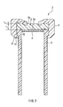
- FIG. 2 is a cross-sectional view showing the communication member shown in FIG. 1 taken along the line II-II.
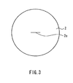
- FIG. 3 is a plan view showing one example of a valve constituting the communication member shown in FIG. 1
- FIG. 4 is a cross-sectional view showing a state where an insertion member is inserted into the communication member shown in FIG. 2 .
- FIG. 5 is a plan view showing another example of the valve constituting the communication member shown in FIG. 1
- FIG. 8 is a plan view showing one example of the medical container using one example of the communication member of the present invention.
- a communication member 1 constitutes a part of a medical container 100 containing a drug solution or the like in advance.
- the communication member 1 is fixed to a container body 30 made of a flexible sheet material.
- the valve 2 has an insertion hole 2a that passes through the valve 2 in its thickness direction.
- the insertion hole 2a is a slit that is formed by, for example, making an incision with a blade or the like in the disc-shaped elastic body whose surface shape is perfect circle. The length or the like of the slit is determined appropriately on the basis of the diameter or the like of an insertion member 10 (see FIG. 4 ) to be inserted into the slit.
- the valve 2 is placed on one end surface of a tubular body 3, and is supported by the tubular body 3.
- a closing film 4 for closing the bore of the tubular body 3 is provided at a position that is within the bore of the tubular body 3 and in the vicinity of the valve 2 so as to block communication between the inside and the outside of the container body 30 (see FIG. 8 ).
- Even without the closing film 4 contact between the drug solution or the like present in the container body and outside air or a leakage of the drug solution from the medical container are supposedly prevented by the valve 2.
- the closing film 4 is to be pierced through by the insertion member 10 (see FIG. 4 ) inserted into the insertion hole 2a when supplying the drug solution or the like present in the container body to the outside of the medical container.
- the vicinity of the valve 2 refers to a position range in which the closing film 4 can be pierced through with the insertion member 10 inserted into the insertion hole 2a.
- the closing film 4 may be in contact with the valve 2, for example.
- the material of the tubular body 3 is a rigid material so as to easily support the valve 2 together with a cover member 5, which will be described below.
- the material is rigid plastic including resins, such as polypropylene, polyethylene, polycarbonate, and polyvinyl chloride. Since the closing film 4 is molded integrally with the tubular body 3 using the following method, the material of the closing film 4 is naturally the same as that of the tubular body 3.
- Examples of the method of molding the tubular body 3 and the closing film 4 include an injection molding method.
- the valve 2 is covered with the cover member 5 at the periphery of its outer surface (the surface opposite to the surface facing the tubular body 3) and its side surface.
- the valve 2 is interposed between the cover member 5 and the tubular body 3.
- the cover member 5 and the valve 2 are fixed firmly to the tubular body 3 by, for example, an engagement between a hook portion 51 of the cover member 5 and a protrusion 31 of the tubular body 3. Since a center portion 2b on which the insertion hole 2a is formed is exposed in the outer surface of the valve 2, the insertion member 10, such as a male luer as defined by ISO594-1 or ISO594-2, can be inserted into the slit 2a of the valve 2 (see FIG. 4 ).
- the insertion hole 2a may be a slit formed by, for example, applying a pressure in the directions of the arrows to an elastic body with an elliptic surface shape on which an elliptic hole 21 is formed, so as to close the elliptic hole 21.
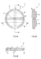
- FIG. 6A is an enlarged plan view showing the closing film constituting the communication member shown in FIG. 1 from the valve side.
- FIG. 6B is a cross-sectional view along the line VIa-VIa in FIG. 6A
- FIG. 6C is a cross-sectional view along the line VIb-VIb in FIG. 6A
- FIG. 7 is an enlarged plan view showing the closing film constituting the communication member shown in FIG. 1 from the surface opposite to the valve side. It should be noted that in order to make the present invention easier to understand, the thickness of the closing film 4 in FIGS. 6B and 6C differs from the actual size.
- a groove 4a that passes through the center X is formed on the surface of the closing film 4 on the valve side. Furthermore, a pair of ribs 4b disposed to interpose the groove 4a are formed on the surface of the closing film 4 opposite to the valve-side surface. That is, one of the pair of ribs 4b is formed on one of the two areas that are divided by a straight line whose longitudinal direction is same as that of the groove 4a and that passes through the center of the closing film 4, and the other rib 4b is formed on the other area.
- the pair of ribs 4b are disposed substantially symmetrically with respect to the center X. However, it is not essential to dispose the pair of ribs 4b disposed to interpose the groove 4 symmetrically as long as the stress concentrates in the vicinity of the center X.
- an end 41b that is closer to the center X has a width that decreases as it gets closer to a tip Y It is further preferable that the tip Y is pointed since the pressure is more likely to concentrate at the center X. Furthermore, it is preferable that the tips Y of the ribs 4b are both in the vicinity of the center X or are located at the center X.
- the tips Y of the ribs 4b both are located at the center X and are coupled to each other at the center X of the closing film 4 since the stress is more likely to concentrate in the vicinity of the center X, and thereby the closing film 4 can be pierced through more easily with the insertion member 10 (see FIG. 4 ).
- the groove 4a has a depth that is substantially constant along the longitudinal direction of the groove 4a, and in the closing film 4, the thickness of the portion of the groove 4a at the center X is equal to the thickness of other portions of the groove 4a.
- the closing film 4 is molded such that the thickness of the portion of the groove 4a in the vicinity of the center X is smaller than that of the remaining portions, it is preferable since the closing film 4 can be pierced through more easily with the insertion member 10 (see FIG. 4 ).
- each of the ribs 4b is formed along a line that passes through the center X and is orthogonal to the groove 4a.
- a straight line whose longitudinal direction is same as that of each of the ribs 4b and which passes through the center X and has a predetermined angle with respect to the longitudinal direction of the groove 4a is orthogonal to the longitudinal direction of the groove 4a. This is because when ripping starts from the vicinity of the center X, it is likely to propagate toward the periphery of the closing film 4 along the groove 4a.
- one or more arc-shaped grooves 4c are formed on the periphery of the surface of the closing film 4 on the valve 2 side. Furthermore, it is preferable that at least one of the one or more arc-shaped grooves 4c is coupled to the groove 4a.
- the number of the arc-shaped grooves 4c formed on the periphery is two or more, it is preferable that they are formed along the circumference of the closing film 4 at an equal interval. It is preferable that a space W between the adjoining arc-shaped grooves 4c in the circumferential direction has such a length that some parts of the ripped closing film 4 do not fall off.
- the number of the arc-shaped grooves 4c is not particularly limited, it is preferable that the number of the arc-shaped grooves is two as shown in FIG. 6A when the number of the groove 4a is one, and the two arc-shaped grooves 4c are preferably both coupled to the groove 4a. In this case, it is possible to reduce the insertion resistance of the insertion member 10 (see FIG. 10 ) while allowing a sufficient length for the space W between the arc-shaped grooves 4c. When the space W between the arc-shaped grooves 4c has a sufficient length, it is possible to prevent some parts of the closing film 4 from falling off or the like.
- the groove 4a is coupled to the arc-shaped grooves 4c in the vicinity of the center of the longitudinal direction of the arc-shaped grooves 4c. In this case, further reduction in the insertion resistance of the insertion member 10 can be expected.
- the number of the arc-shaped groove 4c is one, as shown in FIG. 11 , only one end of the groove 4a may be coupled to the arc-shaped groove 4c so as to prevent some parts of the closing film 4 from falling off.
- the groove 4a, the ribs 4b, and the arc-shaped groove 4c are formed when the closing film 4 is molded integrally with the tubular body 3.
- the communication member 1 including the closing film 4 can be produced without increasing the number of the steps.
- a conventionally known molding method can be used, the production is easy.
- the cross-sectional shape of the groove 4a in its width direction is not particularly limited, and it may be U-shaped, semicircular, concave, or the like. However, it is preferable that the groove 4a has a width that decreases as it gets closer to the bottom so as to allow the stress to concentrate in the vicinity of the center X, and it is particularly preferable that the cross-sectional shape of the groove 4a in the width direction is V-shaped.
- Examples of the cross-sectional shape of the ribs 4b in the width direction include inverse-triangular, semicircular, square, and the like.
- the closing film 4 that constitutes the communication member according to the present embodiment has been described with reference to FIGS. 6 to7, the closing film that constitutes the communication member of the present invention is not limited to this example.
- the tips Y of the ribs 4b may be spaced apart from each other as shown in FIG. 9A . Even in this case, since the stress concentrates on a line that links each of the tips Y and the center X, the closing film 4 can be pierced through easily with the insertion member 10 (see FIG. 4 ).
- the space between the tips Y of the ribs 4b varies from material to material of which the closing film 4 is made, it is preferable that the space is 3 mm or less, and as shown in FIG. 6A , it is particularly preferable that the space is 0 mm. It should be noted that in order to make the present invention easier to understand, the thickness of the closing film 4 differs from the actual size.
- the straight line whose longitudinal direction is same as that of each of the ribs 4b and which passes through the center X is orthogonal to the longitudinal direction of the groove 4a since the stress is likely to concentrate on a straight line that links the tips Y of the pair of ribs.
- the straight line whose longitudinal direction is same as that of each of the ribs 4b and which passes through the center X may be tilted.
- the groove 4a need not be coupled to the arc-shaped groove 4c, and the arc-shaped groove 4c need not be provided.
- the thickness of the closing film 4 at the center X the thickness of the closing film 4 at the portion on which the groove 4a is formed varies from material to material of which the closing film 4 is made, it is preferable that the thickness is from 0.1 to 0.5 mm. This is because too large thickness results in an increase in a penetration resistance and too small thickness makes molding of the film difficult by using an intrusion molding method.
- the thickness is from 0.1 to 0.5 mm. This is because too large thickness results in an increase in a penetration resistance and too small thickness makes molding of the film difficult by using an intrusion molding method.
- the largest thickness t 3 of the closing film 4 at the portions on which the ribs are formed is not particularly limited as long as the effects due to providing the ribs 4b are obtained.
- a thickness t 4 of the closing film 4 at the portion on which none of the arc-shaped groove 4c, the groove 4a, and the ribs 4b is formed varies from material to material of which the closing film 4 is made, it is preferable that the thickness is from 0.2 to 1 mm. This is because too large thickness results in an increase in a penetration resistance and too small thickness makes molding of the film difficult by using an intrusion molding method.
- the silt 2a has a length L 0 of from 2.0 to 4.5 mm in terms of the insertion cap ability and liquid-tightness of the valve 2. It is preferable that the ratio between an outer diameter D 2 of the valve 2 and the length L 0 of the slit satisfies 1.1 ⁇ D 2 /L 0 ⁇ 4.
- the valve 2 has a thickness L 1 of from 1 to 2 mm in terms of the non-return effect, cost efficiency, and the like.
- the valve 2 may be made of a rubber-like elastic material. More restrictively, a material with a hardness JIS-A of 20 to 55 is preferable. Specific examples of the material include synthetic rubbers such as a silicone rubber, a natural rubber, a butyl rubber, and a nitrile rubber, a thermoplastic elastomer, and the like.
- the end surface of the tubular body 3 in contact with the valve 2 is provided with an annular rib 32 that is formed circularly along the inner periphery of the tubular body 3. In this manner, when the annular rib 32 is formed on the end surface, it is possible to prevent liquid leakage between the valve 2 and the tubular body 3 when the insertion member 10 (see FIG. 4 ) is inserted into the slit 2a to pierce through the closing film 4 and to communicate with the tubular body 3.
- the insertion member 10 inserted into the slit 2a can be engaged with the cover 5 by being fitted in a fitting hole 52 formed at the center of the cover 5, for example.
- the insertion member 10 can be engaged with the communication member 1 with a simple configuration.
- the fitting hole 52 has a diameter D 1 of from 3.9 to 4.4 mm (see FIG. 1 ) and a depth L 2 of from 0.3 to 1.0 mm (see FIG. 2 ).
- the cover member 5 has a sufficient strength so that the cover 5 is not cracked even when the insertion member 10 is fitted tightly in the fitting hole 52.
- the cover 5 is made of polyacetal, polypropylene, polyamide, polyethylene terephthalate, polybutylene terephthalate, or the like, for example.
- the ribs 4b may be formed on the surface of the closing film 4 on the valve 2 side and the groove 4a may be formed on the opposite surface.
- the arc-shaped groove 4a is formed on the periphery of the surface of the closing film 4 on which the groove 4a is formed.
- the communication member of the present invention is not limited to such a configuration. As long as the stress concentrates at the center X, the pair of ribs may be formed respectively along separate straight lines that pass through the center of the closing film.
- the communication member of the present invention may include three or more ribs. As long as one of the p air of ribs that are selected from the three or more ribs is formed on one of the two areas that are divided by the straight line whose longitudinal direction is the same as that of the groove and that passes through the center of the closing film, and the other rib is formed on the other area, it is within the scope of the present invention. Also in this case, it is further preferable that the tips of the ribs are coupled to each other at the center of the closing film.
- a plurality of the ribs 4b are formed. It is preferable that a tip of an end of each of the ribs 4b closer to the center of the closing film is in the vicinity of the center X of the closing film, or is located at the center X, each of the ribs 4b is formed along a straight line that passes through the center X of the closing film, and the plurality of the ribs 4b are disposed in a circumferential direction of the closing film at an equal angular interval. Also in this case, it is further preferable that the tips of the ribs are coupled to each other at the center of the closing film.
- the number of the groove 4a is not limited to one and two or more of the grooves 4a that intersect with each other at the center X may be formed.
- Embodiment 2 one example of a medical container using the communication member according to Embodiment 1 will be described with reference to FIG. 8 .
- the medical container 100 includes: the container body 30; and the communication member 1 according to Embodiment 1 that is fixed to the container body 30 and allows communication between the inside and the outside of the container body 30.
- the material of the container body 30 is not particularly limited and examples of the material include a flexible sheet material.
- the sheet material include vinyl chloride resin, polyethylene, ethylene-vinyl acetate copolymer, polyester, polybutadiene, polypropylene, polyamide, ethylene-methacrylate copolymer, polyethylene terephthalate, nylon (trade name) and the like.
- the thickness of the sheet material 2 is also not limited, and the thickness of, for example, about from 0.1 to 0.4 mm is suitable.
- the shape of the container body 30 is also not particularly limited, and the container body 3 may be, for example, rectangular, elliptical, and the like. It is preferable that the lower side of the container body 30 is inclined slightly toward the communication member 1 so that the drug solution or the like present in the medical container 100 can flow easily into the communication member 1.
- the method of fixing the communication member 1 to the container body 30 is not particularly limited and a conventionally-known method may be used.
- a communication member for a medical container that can prevent the contamination of a drug solution with chips and accidental punctures, has excellent stability in storing the drug solution or the like, can be produced easily, and can communicate with an insertion member with an adequate force; and a medical container using the communication member.
- the communication member for a medical container of the present invention can prevent contamination of a drug solution with chips and accidental punctures when used as a component of a medical container. Further it is possible to ensure stability in storing the drug solution or the like. Furthermore, since it can be produced easily and can communicate with an insertion member with an adequate force, it is suitable as a communication member of a medical container.
Landscapes
- Health & Medical Sciences (AREA)
- Pharmacology & Pharmacy (AREA)
- Life Sciences & Earth Sciences (AREA)
- Animal Behavior & Ethology (AREA)
- General Health & Medical Sciences (AREA)
- Public Health (AREA)
- Veterinary Medicine (AREA)
- Medical Preparation Storing Or Oral Administration Devices (AREA)
- Infusion, Injection, And Reservoir Apparatuses (AREA)
Abstract
The present invention provides a communication member for a medical container capable of allowing communication between the inside and the outside of a container body containing a liquid in a state of being fixed to the container body. The communication member includes: a valve 2 having an insertion hole 2a; a tubular body 3 supporting the valve 2; and a closing film 4 for closing a bore of the tubular body 3 in the bore and in the vicinity of the valve 2. The tubular body 3 and the closing film 4 are molded integrally. A groove 4a that passes through the center of the closing film 4 is formed on either a surface of the closing film 4 on the valve 2 side or a surface opposite to the valve side. A pair of ribs 4b are formed on a surface opposite to a surface of the closing film 4 on which the groove is formed, and one of the pair of ribs is formed on one of the two areas that are divided by a straight line whose longitudinal direction is the same as that of the groove and that passes through the center of the closing film, and the other rib is formed on the other area.
Description
- The present invention relates to a communication member that constitutes an opening of a medical container containing a liquid such as a drug solution; and a medical container using the communication member.
- Examples of medical containers include a medical container containing a drug solution for an intravenous drip, a medical container containing a nutritional supplement (also called "high-calorie infusion solution") supplied to the central vein, and the like. These medical containers are composed of a container body made of a flexible sheet material and a liquid discharge port provided for discharging the drug solution or the like present in the container body out of the container body.
- The liquid discharge port is composed of a tube that is welded and fixed to the container body by being sandwiched by a sheet material, a sealing member that seals an end of the tube located outside the container body, and the like. A plug into which a metal injection needle, a resin introducer needle or the like can be inserted is used as the material for the sealing member. The plug is made of, for example, a synthetic rubber or a thermoplastic elastomer. The tube is a relatively-hard molded product made of plastic, for example.
Patent Document 1:JP H08-317961 A - However, when a puncturing member with a sharp tip such as a metal injection needle or a resin intruder needle is used, there is a risk that the drug solution may be contaminated with chips that are chipped away from the plug when puncturing the plug with the puncturing member. Further, the use of the puncturing member with a sharp tip always is accompanied by a danger of accidental punctures.
- Therefore, it may be considered that a valve into which an insertion member without a sharp tip can be inserted is used as the sealing member instead of the plug. An insertion hole that passes through the valve in its thickness direction is formed in advance. Thus, when storing the drug solution or the like, it is necessary to prevent the drug solution from coming into contact with outside air or a leakage of the drug solution from the container through the insertion hole. Furthermore, when the drug solution or the like is stored in a state of being in contact with the sealing member, there is a risk that some parts of the sealing member may be eluted into the drug solution or the like.
- With the foregoing in mind, the present invention provides a communication member for a medical container that can prevent the contamination of a liquid such as a drug solution with chips and accidental punctures, has excellent stability in storing the drug solution or the like, can be produced easily, and can communicate with an insertion member with an adequate force; and a medical container using the communication member.
- The communication member for a medical container of the present invention is a communication member for a medical container capable of allowing communication between the inside and the outside of a container body containing a liquid in a state of being fixed to the container body. The communication member includes: a disc-shaped valve having an insertion hole; a tubular body supporting the valve; and a closing film for closing a bore of the tubular body in the bore and in the vicinity of the valve. The tubular body and the closing film are molded integrally. A groove that passes through a center of the closing film is formed on either a surface of the closing film on a valve side or a surface opposite to the valve side. A pair of ribs are formed on a surface opposite to a surface of the closing film on which the groove is formed. One of the pair of ribs is formed on one of the two areas that are divided by a straight line whose longitudinal direction is same as that of the groove and which passes through the center of the closing film, and the other rib is formed on the other area.
- Further, the communication member for a medical container of the present invention is a communication member for a medical container capable of allowing communication between the inside and the outside of a container body containing a liquid in a state of being fixed to the container body. The communication member includes: a disc-shaped valve having an insertion hole; a tubular body supporting the valve; and a closing film for closing a bore of the tubular body in the bore and in the vicinity of the valve. The tubular body and the closing film are molded integrally. A groove that passes through a center of the closing film is formed on either a surface of the closing film on a valve side or a surface opposite to the valve side. A plurality of ribs are formed on a surface opposite to a surface of the closing film on which the groove is formed, and between both ends of each of the ribs, a tip of an end that is closer to the center of the closing film is in the vicinity of the center of the closing film or located at the center. Each of the ribs is formed along a straight line that passes through the center of the closing film and has a predetermined angle with respect to a longitudinal direction of the groove, and the plurality of ribs are disposed at an equal angular interval in a circumferential direction of the closing film.
- The medical container of the present invention includes: a container body; the communication member of the present invention being fixed to the container body and allowing communication between the inside and the outside of the container body; and a liquid present in the container body.
-
- [
FIG. 11 FIG. 1 is a plan view showing one example of the communication member of the present invention. - [
FIG. 2] FIG. 2 is a cross-sectional view of the communication member shown inFIG. 1 taken along the line II-II. - [
FIG. 3] FIG. 3 is a plan view showing one example of a valve constituting the communication member shown inFIG. 1 . - [
FIG. 4] FIG. 4 is a cross-sectional view showing a state where an insertion member is inserted into the communication member shown inFIG. 2 . - [
FIG. 5] FIG. 5 is a plan view showing another example of the valve constituting the communication member shown inFIG. 1 . - [
FIG. 6] FIG. 6A is an enlarged plan view showing a closing film constituting the communication member shown inFIG. 1 from the valve side.FIG. 6B is a cross-sectional view along the line VIa-VIa inFIG. 6A FIG. 6C is a cross-sectional view along the line VIb-VTb inFIG. 6A . - [
FIG. 7] FIG. 7 is an enlarged plan view showing the closing film constituting the communication member shown inFIG. 1 from a surface opposite to the valve side. - [
FIG. 8] FIG. 8 is a plan view showing one example of the medical container of the present invention. - [
FIG. 9] FIG. 9A is an enlarged plan view showing another example of the closing film constituting the communication member shown inFIG. 1 from the valve side.FIG. 9B is a cross-sectional view along the line VIIIa-VIIIa inFIG. 9A FIG. 9C is a cross-sectional view along the line VIIIb-VIIIb inFIG. 9A . - [
FIG. 10] FIG. 10 is an enlarged plan view showing yet another example of the closing film constituting the communication member shown inFIG. 1 from the valve side. - [
FIG. 11] FIG. 11 is an enlarged plan view showing yet another example of the closing film constituting the communication member shown inFIG. 1 from the valve side. - [
FIG. 12] FIG. 12 is an enlarged plan view showing yet another example of the closing film constituting the communication member shown inFIG. 1 from the valve side. - In one preferred example of the communication member for a medical container of the present invention, each of the pair of ribs is formed along a straight line that passes through the center of the closing film and has a predetermined angle with respect to the longitudinal direction of the groove.
- In one preferred example of the communication member for a medical container of the present invention, the groove has a width that decreases as it get closer to the bottom. In a particularly preferred example, the cross-sectional shape of the groove in its width direction at the bottom is V-shaped.
- In one preferred example of the communication member for a medical container of the present invention, the communication member further includes a cover member that interposes the valve together with the tubular body and covers a periphery of an outer surface of the valve.
- In one preferred example of the communication member for a medical container of the present invention, the pair of ribs are formed symmetrically with respect to the center of the closing film.
- In one preferred example of the communication member for a medical container of the present invention, between both end portions of each of the ribs, a tip portion of an end portion that is closer to the center of the closing film has a width that decreases as it gets closer to a tip, and the tip of each of the ribs is on a straight line whose longitudinal direction is the same as that of each of the ribs and which passes through the center of the closing film. More preferably, the tip is pointed.
- In one preferred example of the communication member for a medical container of the present invention, the tip of the end of each of the ribs that is closer to the center of the closing film is in the vicinity of the center of the closing film or located at the center, and more preferably the tips of the pair of ribs are coupled to each other at the center of the closing film.
- In one preferred example of the communication member for a medical container of the present invention, the pair of ribs are both
formed along one straight line that passes through the center of the closing film and has a predetermined angle with respect to the longitudinal direction of the groove. In this case, it is preferable that the straight line is orthogonal to the longitudinal direction of the groove. - In one preferred example of the communication member for a medical container of the present invention, the closing film and the tubular body include at least one type of resin selected from a group consisting of polyethylene, polypropylene, cyclic polyolefin, polyethylene terephthalate, and polyvinyl chloride.
- In one preferred example of the communication member for a medical container of the present invention, one or more arc-shaped grooves are formed on the periphery of the surface of the closing film on which the groove is formed. More preferably, at least one of the one or more arc-shaped grooves is coupled to the groove.
- Next, the present invention will be described in more detail with reference to the drawings.
- In
Embodiment 1, one example of the communication member for a medical container of the present invention (hereinafter referred also to as simply "the communication member") and one example of the medical container using the communication member will be described. -
FIG. 1 is a plan view showing one example of the communication member of the present invention, andFIG. 2 is a cross-sectional view showing the communication member shown inFIG. 1 taken along the line II-II.FIG. 3 is a plan view showing one example of a valve constituting the communication member shown inFIG. 1 , andFIG. 4 is a cross-sectional view showing a state where an insertion member is inserted into the communication member shown inFIG. 2 .FIG. 5 is a plan view showing another example of the valve constituting the communication member shown inFIG. 1 .FIG. 8 is a plan view showing one example of the medical container using one example of the communication member of the present invention. - As shown in
FIG. 8 , acommunication member 1 according to the present embodiment constitutes a part of amedical container 100 containing a drug solution or the like in advance. Thecommunication member 1 is fixed to acontainer body 30 made of a flexible sheet material. - As shown in
FIGS. 1 and2 , thecommunication member 1, which is one example of the present invention, includes a disc-shapedvalve 2, for example. Thevalve 2 has aninsertion hole 2a that passes through thevalve 2 in its thickness direction. As shown inFIG. 3 , theinsertion hole 2a is a slit that is formed by, for example, making an incision with a blade or the like in the disc-shaped elastic body whose surface shape is perfect circle. The length or the like of the slit is determined appropriately on the basis of the diameter or the like of an insertion member 10 (seeFIG. 4 ) to be inserted into the slit. - As shown in
FIG. 2 , thevalve 2 is placed on one end surface of atubular body 3, and is supported by thetubular body 3. Aclosing film 4 for closing the bore of thetubular body 3 is provided at a position that is within the bore of thetubular body 3 and in the vicinity of thevalve 2 so as to block communication between the inside and the outside of the container body 30 (seeFIG. 8 ). Even without theclosing film 4, contact between the drug solution or the like present in the container body and outside air or a leakage of the drug solution from the medical container are supposedly prevented by thevalve 2. However, those problems can be prevented with more certainty by providing theclosing film 4. Theclosing film 4 is to be pierced through by the insertion member 10 (seeFIG. 4 ) inserted into theinsertion hole 2a when supplying the drug solution or the like present in the container body to the outside of the medical container. - It should noted that "the vicinity of the
valve 2" refers to a position range in which theclosing film 4 can be pierced through with theinsertion member 10 inserted into theinsertion hole 2a. Thus, theclosing film 4 may be in contact with thevalve 2, for example. - It is preferable that the material of the
tubular body 3 is a rigid material so as to easily support thevalve 2 together with acover member 5, which will be described below. For example, it is preferable that the material is rigid plastic including resins, such as polypropylene, polyethylene, polycarbonate, and polyvinyl chloride. Since theclosing film 4 is molded integrally with thetubular body 3 using the following method, the material of theclosing film 4 is naturally the same as that of thetubular body 3. - Examples of the method of molding the
tubular body 3 and theclosing film 4 include an injection molding method. - As shown in
FIG. 2 , thevalve 2 is covered with thecover member 5 at the periphery of its outer surface (the surface opposite to the surface facing the tubular body 3) and its side surface. Thevalve 2 is interposed between thecover member 5 and thetubular body 3. Further, thecover member 5 and thevalve 2 are fixed firmly to thetubular body 3 by, for example, an engagement between ahook portion 51 of thecover member 5 and aprotrusion 31 of thetubular body 3. Since acenter portion 2b on which theinsertion hole 2a is formed is exposed in the outer surface of thevalve 2, theinsertion member 10, such as a male luer as defined by ISO594-1 or ISO594-2, can be inserted into theslit 2a of the valve 2 (seeFIG. 4 ). - It should be noted that, as shown in
FIG. 5 , theinsertion hole 2a may be a slit formed by, for example, applying a pressure in the directions of the arrows to an elastic body with an elliptic surface shape on which anelliptic hole 21 is formed, so as to close theelliptic hole 21. - Next, one example of the
closing film 4 will be described with reference toFIGS. 6 to 7 . -
FIG. 6A is an enlarged plan view showing the closing film constituting the communication member shown inFIG. 1 from the valve side.FIG. 6B is a cross-sectional view along the line VIa-VIa inFIG. 6A, and FIG. 6C is a cross-sectional view along the line VIb-VIb inFIG. 6A FIG. 7 is an enlarged plan view showing the closing film constituting the communication member shown inFIG. 1 from the surface opposite to the valve side. It should be noted that in order to make the present invention easier to understand, the thickness of theclosing film 4 inFIGS. 6B and 6C differs from the actual size. - As shown in
FIGS. 6 to 7 , agroove 4a that passes through the center X is formed on the surface of theclosing film 4 on the valve side. Furthermore, a pair ofribs 4b disposed to interpose thegroove 4a are formed on the surface of theclosing film 4 opposite to the valve-side surface. That is, one of the pair ofribs 4b is formed on one of the two areas that are divided by a straight line whose longitudinal direction is same as that of thegroove 4a and that passes through the center of theclosing film 4, and theother rib 4b is formed on the other area. Thus, when the insertion member 10 (seeFIG. 4 ) inserted into theinsertion hole 2a (seeFIG. 2 ) imposes a load on theclosing film 4, a stress generated within theclosing film 4 concentrates at a position that is between the pair ofribs 4b and in the vicinity of the center X. Therefore, even when theclosing film 4 is a relatively rigid plastic molded product, it is possible to pierce easily through theclosing film 4 with theinsertion member 10 that has no sharp tip like a luer or the like. It should be noted that in the example shown inFIGS. 6 to 7 , the pair ofribs 4b are disposed substantially symmetrically with respect to the center X. However, it is not essential to dispose the pair ofribs 4b disposed to interpose thegroove 4 symmetrically as long as the stress concentrates in the vicinity of the center X. - As shown in
FIG. 7 , between both ends of each of theribs 4b, anend 41b that is closer to the center X has a width that decreases as it gets closer to a tip Y It is further preferable that the tip Y is pointed since the pressure is more likely to concentrate at the center X. Furthermore, it is preferable that the tips Y of theribs 4b are both in the vicinity of the center X or are located at the center X. It is particularly preferable that the tips Y of theribs 4b both are located at the center X and are coupled to each other at the center X of theclosing film 4 since the stress is more likely to concentrate in the vicinity of the center X, and thereby theclosing film 4 can be pierced through more easily with the insertion member 10 (seeFIG. 4 ). - It should be noted that in the example shown in
FIGS. 6 to 7 , thegroove 4a has a depth that is substantially constant along the longitudinal direction of thegroove 4a, and in theclosing film 4, the thickness of the portion of thegroove 4a at the center X is equal to the thickness of other portions of thegroove 4a. However, if theclosing film 4 is molded such that the thickness of the portion of thegroove 4a in the vicinity of the center X is smaller than that of the remaining portions, it is preferable since theclosing film 4 can be pierced through more easily with the insertion member 10 (seeFIG. 4 ). - Further, as shown in
FIG. 7 , it is preferable that each of theribs 4b is formed along a line that passes through the center X and is orthogonal to thegroove 4a. In other words, it is preferable that a straight line whose longitudinal direction is same as that of each of theribs 4b and which passes through the center X and has a predetermined angle with respect to the longitudinal direction of thegroove 4a is orthogonal to the longitudinal direction of thegroove 4a. This is because when ripping starts from the vicinity of the center X, it is likely to propagate toward the periphery of theclosing film 4 along thegroove 4a. - As shown in
FIGS. 6A and 6B , it is further preferable that one or more arc-shapedgrooves 4c are formed on the periphery of the surface of theclosing film 4 on thevalve 2 side. Furthermore, it is preferable that at least one of the one or more arc-shapedgrooves 4c is coupled to thegroove 4a. When the number of the arc-shapedgrooves 4c formed on the periphery is two or more, it is preferable that they are formed along the circumference of theclosing film 4 at an equal interval. It is preferable that a space W between the adjoining arc-shapedgrooves 4c in the circumferential direction has such a length that some parts of the rippedclosing film 4 do not fall off. In this case, since ripping that started from the vicinity of the center X may propagate further along the arc-shapedgrooves 4c after reaching the periphery of theclosing film 4, the insertion resistance of the insertion member 10 (seeFIG. 4 ) is reduced further. - Although the number of the arc-shaped
grooves 4c is not particularly limited, it is preferable that the number of the arc-shaped grooves is two as shown inFIG. 6A when the number of thegroove 4a is one, and the two arc-shapedgrooves 4c are preferably both coupled to thegroove 4a. In this case, it is possible to reduce the insertion resistance of the insertion member 10 (seeFIG. 10 ) while allowing a sufficient length for the space W between the arc-shapedgrooves 4c. When the space W between the arc-shapedgrooves 4c has a sufficient length, it is possible to prevent some parts of theclosing film 4 from falling off or the like. Furthermore, it is preferable that thegroove 4a is coupled to the arc-shapedgrooves 4c in the vicinity of the center of the longitudinal direction of the arc-shapedgrooves 4c. In this case, further reduction in the insertion resistance of theinsertion member 10 can be expected. - When the number of the arc-shaped
groove 4c is one, as shown inFIG. 11 , only one end of thegroove 4a may be coupled to the arc-shapedgroove 4c so as to prevent some parts of theclosing film 4 from falling off. - The
groove 4a, theribs 4b, and the arc-shapedgroove 4c are formed when theclosing film 4 is molded integrally with thetubular body 3. Thus, thecommunication member 1 including theclosing film 4 can be produced without increasing the number of the steps. Furthermore, since a conventionally known molding method can be used, the production is easy. - The cross-sectional shape of the
groove 4a in its width direction is not particularly limited, and it may be U-shaped, semicircular, concave, or the like. However, it is preferable that thegroove 4a has a width that decreases as it gets closer to the bottom so as to allow the stress to concentrate in the vicinity of the center X, and it is particularly preferable that the cross-sectional shape of thegroove 4a in the width direction is V-shaped. - Examples of the cross-sectional shape of the
ribs 4b in the width direction include inverse-triangular, semicircular, square, and the like. - Although one example of the
closing film 4 that constitutes the communication member according to the present embodiment has been described with reference toFIGS. 6 to7, the closing film that constitutes the communication member of the present invention is not limited to this example. For example, as long as the effects of the present invention can be obtained, the tips Y of theribs 4b may be spaced apart from each other as shown inFIG. 9A . Even in this case, since the stress concentrates on a line that links each of the tips Y and the center X, theclosing film 4 can be pierced through easily with the insertion member 10 (seeFIG. 4 ). Although the space between the tips Y of theribs 4b varies from material to material of which theclosing film 4 is made, it is preferable that the space is 3 mm or less, and as shown inFIG. 6A , it is particularly preferable that the space is 0 mm. It should be noted that in order to make the present invention easier to understand, the thickness of theclosing film 4 differs from the actual size. - Further, it is preferable that the straight line whose longitudinal direction is same as that of each of the
ribs 4b and which passes through the center X is orthogonal to the longitudinal direction of thegroove 4a since the stress is likely to concentrate on a straight line that links the tips Y of the pair of ribs. However, as shown inFIG. 10 , the straight line whose longitudinal direction is same as that of each of theribs 4b and which passes through the center X may be tilted. Further, thegroove 4a need not be coupled to the arc-shapedgroove 4c, and the arc-shapedgroove 4c need not be provided. - As shown in
FIGS. 6C and9C , although the smallest thickness t1 (the thickness of theclosing film 4 at the center X) of theclosing film 4 at the portion on which thegroove 4a is formed varies from material to material of which theclosing film 4 is made, it is preferable that the thickness is from 0.1 to 0.5 mm. This is because too large thickness results in an increase in a penetration resistance and too small thickness makes molding of the film difficult by using an intrusion molding method. - As shown in
FIGS. 6B and9B , although the smallest thickness t2 of theclosing film 4 at the portions on which the arc-shapedgrooves 4c are formed varies from material to material of which theclosing film 4 is made, it is preferable that the thickness is from 0.1 to 0.5 mm. This is because too large thickness results in an increase in a penetration resistance and too small thickness makes molding of the film difficult by using an intrusion molding method. - The largest thickness t3 of the
closing film 4 at the portions on which the ribs are formed is not particularly limited as long as the effects due to providing theribs 4b are obtained. - Although a thickness t4 of the
closing film 4 at the portion on which none of the arc-shapedgroove 4c, thegroove 4a, and theribs 4b is formed varies from material to material of which theclosing film 4 is made, it is preferable that the thickness is from 0.2 to 1 mm. This is because too large thickness results in an increase in a penetration resistance and too small thickness makes molding of the film difficult by using an intrusion molding method. - When the insertion member 10 (see
FIG. 4 ) is a general male luer, it is preferable that thesilt 2a has a length L0 of from 2.0 to 4.5 mm in terms of the insertion cap ability and liquid-tightness of thevalve 2. It is preferable that the ratio between an outer diameter D2 of thevalve 2 and the length L0 of the slit satisfies 1.1 ≤ D2/L0 ≤ 4. - As shown in
FIG. 2 , it is preferable that thevalve 2 has a thickness L1 of from 1 to 2 mm in terms of the non-return effect, cost efficiency, and the like. Thevalve 2 may be made of a rubber-like elastic material. More restrictively, a material with a hardness JIS-A of 20 to 55 is preferable. Specific examples of the material include synthetic rubbers such as a silicone rubber, a natural rubber, a butyl rubber, and a nitrile rubber, a thermoplastic elastomer, and the like. - It is preferable that the end surface of the
tubular body 3 in contact with thevalve 2 is provided with anannular rib 32 that is formed circularly along the inner periphery of thetubular body 3. In this manner, when theannular rib 32 is formed on the end surface, it is possible to prevent liquid leakage between thevalve 2 and thetubular body 3 when the insertion member 10 (seeFIG. 4 ) is inserted into theslit 2a to pierce through theclosing film 4 and to communicate with thetubular body 3. - As shown in
FIG. 4 , theinsertion member 10 inserted into theslit 2a can be engaged with thecover 5 by being fitted in afitting hole 52 formed at the center of thecover 5, for example. In this case, theinsertion member 10 can be engaged with thecommunication member 1 with a simple configuration. - In the case where the
insertion member 10 is a male luer with a 6/100 tapered surface as defined by the international standard (ISO594-1), it is preferable that thefitting hole 52 has a diameter D1 of from 3.9 to 4.4 mm (seeFIG. 1 ) and a depth L2 of from 0.3 to 1.0 mm (seeFIG. 2 ). - It is preferable that the
cover member 5 has a sufficient strength so that thecover 5 is not cracked even when theinsertion member 10 is fitted tightly in thefitting hole 52. On this account, it is preferable that thecover 5 is made of polyacetal, polypropylene, polyamide, polyethylene terephthalate, polybutylene terephthalate, or the like, for example. - As shown in
FIG. 1 , it is preferable that 1.1 ≤ D2/L0 ≤ 4 is satisfied in terms of ease of insertion of theinsertion member 10 into theinsertion hole 2a, the non-return effect, and the like. When the length L0 of theinsertion hole 2a is too long, i.e., D2/L0 is smaller than 1.1, it is feared that the valve is deformed and broken (torn) by inserting theinsertion member 10 into theinsertion hole 2a. In addition, a peripheral portion of the valve that is deformable (when the insertion member is inserted into the insertion hole) becomes smaller with respect to theinsertion hole 2a, resulting in difficulty in inserting theinsertion member 10 into theinsertion hole 2a. On the other hand, when D2/L0 is larger than 4, it becomes easier to insert theinsertion member 10 into the valve. However, the valve, thecover member 5, and the like become larger, resulting in a cost increase. - A description will be given of the relationship between the length L0 of the slit (see
FIG. 1 ) as theinsertion hole 2a and the insertion member 10 (seeFIG. 4 ). As shown inFIG. 4 , it is assumed that in a state where theinsertion member 10 is engaged with thefitting hole 52, a maximum diameter of a portion of theinsertion member 10 that is buried in thevalve 2 in contact therewith is an insertion portion diameter D3. In this case, it is preferable that the length L0 of the slit (seeFIG. 1 ) is 0.7 times or more and 1.1 times or less the insertion portion diameter D3. When L0 is smaller than this range, it becomes difficult to insert theinsertion member 10. When L0 is larger than this range, air easily leaks from theinsertion hole 2a when theinsertion member 10 is extracted from theinsertion hole 2a. - Although the above description has illustrated an example of the
groove 4c being formed on the surface of theclosing film 4 on thevalve 2 side, and theribs 4b being formed on the opposite surface, theribs 4b may be formed on the surface of theclosing film 4 on thevalve 2 side and thegroove 4a may be formed on the opposite surface. When forming the arc-shapedgroove 4a in this case, the arc-shapedgroove 4a is formed on the periphery of the surface of theclosing film 4 on which thegroove 4a is formed. - Further, although the above description has illustrated one example of the communication member of the present invention with reference to an example of the pair of ribs being formed along one straight line that passes through the center of the closing film, the communication member of the present invention is not limited to such a configuration. As long as the stress concentrates at the center X, the pair of ribs may be formed respectively along separate straight lines that pass through the center of the closing film.
- Although the above description has illustrated one example of the communication member of the present invention with reference to an example of including two ribs, the communication member of the present invention is not limited to such a configuration. The communication member of the present invention may include three or more ribs. As long as one of the p air of ribs that are selected from the three or more ribs is formed on one of the two areas that are divided by the straight line whose longitudinal direction is the same as that of the groove and that passes through the center of the closing film, and the other rib is formed on the other area, it is within the scope of the present invention. Also in this case, it is further preferable that the tips of the ribs are coupled to each other at the center of the closing film.
- Further, as shown in
FIG. 12 , in one example of the communication member of the present invention, a plurality of theribs 4b are formed. It is preferable that a tip of an end of each of theribs 4b closer to the center of the closing film is in the vicinity of the center X of the closing film, or is located at the center X, each of theribs 4b is formed along a straight line that passes through the center X of the closing film, and the plurality of theribs 4b are disposed in a circumferential direction of the closing film at an equal angular interval. Also in this case, it is further preferable that the tips of the ribs are coupled to each other at the center of the closing film. - The number of the
groove 4a is not limited to one and two or more of thegrooves 4a that intersect with each other at the center X may be formed. - In
Embodiment 2, one example of a medical container using the communication member according toEmbodiment 1 will be described with reference toFIG. 8 . - As shown in
FIG. 8 , themedical container 100 according to the present embodiment includes: thecontainer body 30; and thecommunication member 1 according toEmbodiment 1 that is fixed to thecontainer body 30 and allows communication between the inside and the outside of thecontainer body 30. - The material of the
container body 30 is not particularly limited and examples of the material include a flexible sheet material. Examples of the sheet material include vinyl chloride resin, polyethylene, ethylene-vinyl acetate copolymer, polyester, polybutadiene, polypropylene, polyamide, ethylene-methacrylate copolymer, polyethylene terephthalate, nylon (trade name) and the like. The thickness of thesheet material 2 is also not limited, and the thickness of, for example, about from 0.1 to 0.4 mm is suitable. - The shape of the
container body 30 is also not particularly limited, and thecontainer body 3 may be, for example, rectangular, elliptical, and the like. It is preferable that the lower side of thecontainer body 30 is inclined slightly toward thecommunication member 1 so that the drug solution or the like present in themedical container 100 can flow easily into thecommunication member 1. - The method of fixing the
communication member 1 to thecontainer body 30 is not particularly limited and a conventionally-known method may be used. - As described above, according to the present invention, it is possible to provide a communication member for a medical container that can prevent the contamination of a drug solution with chips and accidental punctures, has excellent stability in storing the drug solution or the like, can be produced easily, and can communicate with an insertion member with an adequate force; and a medical container using the communication member.
- The communication member for a medical container of the present invention can prevent contamination of a drug solution with chips and accidental punctures when used as a component of a medical container. Further it is possible to ensure stability in storing the drug solution or the like. Furthermore, since it can be produced easily and can communicate with an insertion member with an adequate force, it is suitable as a communication member of a medical container.
Claims (16)
- A communication member for a medical container capable of allowing communication between an inside and an outside of a container body containing a liquid in a state of being fixed to the container body, the communication member comprising:a disc-shaped valve having an insertion hole;a tubular body supporting the valve; anda closing film for closing a bore of the tubular body in the bore and in the vicinity of the valve,wherein the tubular body and the closing film are molded integrally,a groove that passes through a center of the closing film is formed on either a surface of the closing film on a valve side or a surface opposite to the valve side,a pair of ribs are formed on a surface opposite to a surface of the closing film on which the groove is formed, andone of the pair of ribs is formed on one of the two areas that is divided by a straight line whose longitudinal direction is same as that of the groove and which passes through the center of the closing film, and the other rib is formed on the other area.
- The communication member for a medical container according to claim 1, wherein each of the pair of ribs is formed along a straight line that passes through the center of the closing film and has a predetermined angle with respect to the longitudinal direction of the groove.
- The communication member for a medical container according to claim 1, wherein the groove has a width that decreases as it gets closer to a bottom.
- The communication member for a medical container according to claim 1 further includes a cover member that interposes the valve together with the tubular body and covers a periphery of an outer surface of the valve.
- The communication member for a medical container according to claim 1, wherein the pair of ribs are formed symmetrically with respect to the center of the closing film.
- The communication member for a medical container according to claim 1, wherein between both end portions of each of the ribs, a tip portion of an end portion that is closer to the center of the closing film has a width that decreases as it gets closer to a tip.
- The communication member for a medical container according to claim 6, wherein the tip of each of the ribs is on a straight line whose longitudinal direction is the same as that of each of the ribs and that passes through the center of the closing film.
- The communication member for a medical container according to claim 5, wherein the tip of the end of each of the ribs that is closer to the center of the closing film is in the vicinity of the center of the closing film or located at the center.
- The communication member for a medical container according to claim 7, wherein the tips of the pair of ribs are coupled to each other at the center of the closing film.
- The communication member for a medical container according to claim 1, wherein the pair of ribs are both formed along one straight line that passes through the center of the closing film and has a predetermined angle with respect to the longitudinal direction of the groove.
- The communication member for a medical container according to claim 10, wherein the straight line is orthogonal to the longitudinal direction of the groove.
- The communication member for a medical container according to claim 1, wherein the closing film and the tubular body include at least one type of resin selected from a group consisting of polyethylene, polypropylene, cyclic polyolefin, polyethylene terephthalate, and polyvinyl chloride.
- The communication member for a medical container according to claim 1, wherein one or more arc-shaped grooves are formed on the periphery of the surface of the closing film on which the groove is formed.
- The communication member for a medical container according to claim 13, wherein at least one of the one or more arc-shaped grooves is coupled to the groove.
- A communication member for a medical container capable of allowing communication between an inside and an outside of a container body containing a liquid in a state of being fixed to the container body, the communication member comprising:a disc-shaped valve having an insertion hole;a tubular body supporting the valve; anda closing film for closing a bore of the tubular body in the bore and in the vicinity of the valve,wherein the tubular body and the closing film are molded integrally,a groove that passes through a center of the closing film is formed on either a surface of the closing film on a valve side or a surface opposite to the valve side,a plurality of ribs are formed on a surface opposite to a surface of the closing film on which the groove is formed,between both ends of each of the ribs, a tip of an end that is closer to the center of the closing film is in the vicinity of the center of the closing film or located at the center,each of the ribs is formed along a straight line that passes through the center of the closing film and has a predetermined angle with respect to a longitudinal direction of the groove, andthe plurality of ribs are disposed at an equal angular interval in a circumferential direction of the closing film.
- A medical container comprising:a container body;the communication member according to any one of claims 1 to 15 being fixed to the container body and allowing communication between the inside and the outside of the container body; anda liquid present in the container body.
Applications Claiming Priority (2)
| Application Number | Priority Date | Filing Date | Title |
|---|---|---|---|
| JP2006282928 | 2006-10-17 | ||
| PCT/JP2007/070269 WO2008050655A1 (en) | 2006-10-17 | 2007-10-17 | Communication member and medical container using the same |
Publications (1)
| Publication Number | Publication Date |
|---|---|
| EP2074982A1 true EP2074982A1 (en) | 2009-07-01 |
Family
ID=39324454
Family Applications (1)
| Application Number | Title | Priority Date | Filing Date |
|---|---|---|---|
| EP07830003A Withdrawn EP2074982A1 (en) | 2006-10-17 | 2007-10-17 | Communication member and medical container using the same |
Country Status (5)
| Country | Link |
|---|---|
| US (1) | US8056756B2 (en) |
| EP (1) | EP2074982A1 (en) |
| JP (1) | JP4936081B2 (en) |
| CN (1) | CN101528180B (en) |
| WO (1) | WO2008050655A1 (en) |
Families Citing this family (10)
| Publication number | Priority date | Publication date | Assignee | Title |
|---|---|---|---|---|
| JP5729745B2 (en) | 2009-09-15 | 2015-06-03 | ルネサスエレクトロニクス株式会社 | Semiconductor device and manufacturing method thereof |
| FR2950035B1 (en) | 2009-09-15 | 2011-09-02 | Raymond A & Cie | LOCKING COIFFE FOR CONTAINER WITH COLLAR |
| FR2950865B1 (en) | 2009-10-01 | 2011-10-28 | Raymond A & Cie | LOCKING CAP FOR A COLLARED CONTAINER WITH A FASTENING CAPSULE |
| US20130098861A1 (en) * | 2011-10-19 | 2013-04-25 | Neomed, Inc. | Fluid containment sytem with nipple adapter |
| FR2986782B1 (en) | 2012-02-13 | 2014-03-07 | Raymond A & Cie | PLUG LOCKING DEVICE ON FLANGE CONTAINER, PLUG-IN CLOSURE FLANGE CONTAINER PROVIDED WITH SUCH LATCHING DEVICE |
| US9114231B2 (en) * | 2013-03-15 | 2015-08-25 | B. Braun Melsungen Ag | Valved catheter assemblies and related methods |
| EP3552652B2 (en) | 2015-08-18 | 2024-07-03 | B. Braun Melsungen AG | Catheter devices with valves |
| DE102017000048A1 (en) * | 2017-01-05 | 2018-07-05 | Kocher-Plastik Maschinenbau Gmbh | container |
| WO2020127328A1 (en) | 2018-12-17 | 2020-06-25 | B. Braun Melsungen Ag | Over-the-needle catheter assemblies and related manufacturing method |
| KR102444632B1 (en) * | 2020-06-02 | 2022-09-19 | 주식회사 삼화 | Leak-proof port on infusion bag |
Family Cites Families (22)
| Publication number | Priority date | Publication date | Assignee | Title |
|---|---|---|---|---|
| JPH0228916Y2 (en) * | 1987-06-23 | 1990-08-02 | ||
| JP2598094B2 (en) | 1988-07-19 | 1997-04-09 | ニチコン株式会社 | Electrolyte for driving electrolytic capacitors |
| GB9103122D0 (en) * | 1991-02-14 | 1991-04-03 | Wallace Ltd H G | Resealable sampling port |
| US5147065A (en) * | 1991-11-04 | 1992-09-15 | James River Corporation Of Virginia | Disposable cup lid having a tear-resistant straw slot |
| JP3409943B2 (en) | 1995-05-25 | 2003-05-26 | 昭和電工株式会社 | Plug for infusion container and method for producing the same |
| EP0895466A1 (en) * | 1996-04-22 | 1999-02-10 | Abbott Laboratories | Container closure system |
| US5871110A (en) * | 1996-09-13 | 1999-02-16 | Grimard; Jean-Pierre | Transfer assembly for a medicament container having a splashless valve |
| JP2955854B1 (en) | 1998-04-24 | 1999-10-04 | 株式会社グッドマン | Hemostatic valve of catheter introducer |
| DE69940078D1 (en) * | 1998-07-13 | 2009-01-22 | Jms Co Ltd | Medical hose connection device |
| DE19852557C2 (en) * | 1998-11-13 | 2002-11-07 | Fresenius Medical Care De Gmbh | closure element |
| WO2000063088A1 (en) | 1999-04-20 | 2000-10-26 | Jms Co., Ltd. | Cap for container and adaptor for liquid communication |
| US6213322B1 (en) * | 1999-11-17 | 2001-04-10 | Eastman Kodak Company | Container for photoprocessing materials |
| JP4048431B2 (en) * | 2000-12-04 | 2008-02-20 | 株式会社ジェイ・エム・エス | Chemical container stopper |
| JP4370552B2 (en) | 2001-09-14 | 2009-11-25 | ニプロ株式会社 | Chemical solution injection port |
| DE10223560B4 (en) * | 2002-05-27 | 2006-01-19 | Fresenius Kabi Deutschland Gmbh | Connector for medical fluid containing packaging and packaging for medical fluids |
| JP2004283519A (en) * | 2003-01-27 | 2004-10-14 | Otsuka Pharmaceut Factory Inc | Cap and medical container using the same |
| JP4299553B2 (en) * | 2003-02-20 | 2009-07-22 | テルモ株式会社 | Medical container |
| JP2005028041A (en) * | 2003-07-11 | 2005-02-03 | Medicalseed:Kk | Sealing plug for partition bag |
| US7951121B2 (en) * | 2003-07-30 | 2011-05-31 | Navilyst Medical, Inc. | Pressure actuated valve with improved slit configuration |
| US20060226113A1 (en) * | 2005-04-06 | 2006-10-12 | Clark Douglas P | Liquid vial closure with improved anti-evaporation features |
| US20080006558A1 (en) * | 2006-07-05 | 2008-01-10 | Thrapp Stephen R | Easy access refuse container |
| US7918826B2 (en) * | 2007-09-14 | 2011-04-05 | Ethicon Endo-Surgery, Inc. | Trocar assembly |
-
2007
- 2007-10-17 US US12/445,888 patent/US8056756B2/en not_active Expired - Fee Related
- 2007-10-17 WO PCT/JP2007/070269 patent/WO2008050655A1/en not_active Ceased
- 2007-10-17 JP JP2008540955A patent/JP4936081B2/en not_active Expired - Fee Related
- 2007-10-17 EP EP07830003A patent/EP2074982A1/en not_active Withdrawn
- 2007-10-17 CN CN200780038584XA patent/CN101528180B/en not_active Expired - Fee Related
Non-Patent Citations (1)
| Title |
|---|
| See references of WO2008050655A1 * |
Also Published As
| Publication number | Publication date |
|---|---|
| JPWO2008050655A1 (en) | 2010-02-25 |
| JP4936081B2 (en) | 2012-05-23 |
| CN101528180B (en) | 2012-09-26 |
| WO2008050655A1 (en) | 2008-05-02 |
| CN101528180A (en) | 2009-09-09 |
| US8056756B2 (en) | 2011-11-15 |
| US20100288722A1 (en) | 2010-11-18 |
Similar Documents
| Publication | Publication Date | Title |
|---|---|---|
| US8056756B2 (en) | Communication member and medical container using the same | |
| JP4775638B2 (en) | Communication member, medical container using the same, and infusion dispensing device set | |
| JP4533887B2 (en) | Connector for pack containing medical fluid and pack for medical fluid | |
| US8118802B2 (en) | Connector for packaging containing medical fluids and packaging for medical fluids | |
| EP0495497B1 (en) | Intravenous catheter | |
| US7857802B2 (en) | Connector for medical liquid-containing packages and medical liquid-containing packages | |
| US8827978B2 (en) | Bag connector | |
| JP3594604B2 (en) | Fluid port resealing member | |
| EP1884260A1 (en) | Fluid mixture delivery instrument | |
| EP2420219B1 (en) | An administration port | |
| ES2798750T3 (en) | Connector system for medical fluid administration | |
| KR20120085279A (en) | Cap, and nutritional agent container and nutritional agent supply set that use same | |
| WO2007027567A1 (en) | Medical fluid container system having needle-free connection | |
| JP5051510B2 (en) | Communication member and medical container using the same | |
| JP6731143B2 (en) | Priming cap | |
| JP2004129868A (en) | Mouth member and liquid medicine container provided therewith |
Legal Events
| Date | Code | Title | Description |
|---|---|---|---|
| PUAI | Public reference made under article 153(3) epc to a published international application that has entered the european phase |
Free format text: ORIGINAL CODE: 0009012 |
|
| 17P | Request for examination filed |
Effective date: 20090417 |
|
| AK | Designated contracting states |
Kind code of ref document: A1 Designated state(s): AT BE BG CH CY CZ DE DK EE ES FI FR GB GR HU IE IS IT LI LT LU LV MC MT NL PL PT RO SE SI SK TR |
|
| AX | Request for extension of the european patent |
Extension state: AL BA HR MK RS |
|
| DAX | Request for extension of the european patent (deleted) | ||
| STAA | Information on the status of an ep patent application or granted ep patent |
Free format text: STATUS: THE APPLICATION HAS BEEN WITHDRAWN |
|
| 18W | Application withdrawn |
Effective date: 20130906 |
|
| P01 | Opt-out of the competence of the unified patent court (upc) registered |
Effective date: 20230428 |