JP4370552B2 - Chemical solution injection port - Google Patents
Chemical solution injection port Download PDFInfo
- Publication number
- JP4370552B2 JP4370552B2 JP2002231489A JP2002231489A JP4370552B2 JP 4370552 B2 JP4370552 B2 JP 4370552B2 JP 2002231489 A JP2002231489 A JP 2002231489A JP 2002231489 A JP2002231489 A JP 2002231489A JP 4370552 B2 JP4370552 B2 JP 4370552B2
- Authority
- JP
- Japan
- Prior art keywords
- chemical
- chemical solution
- injection port
- discharge port
- injection
- Prior art date
- Legal status (The legal status is an assumption and is not a legal conclusion. Google has not performed a legal analysis and makes no representation as to the accuracy of the status listed.)
- Expired - Lifetime
Links
Images


Classifications
-
- B—PERFORMING OPERATIONS; TRANSPORTING
- B65—CONVEYING; PACKING; STORING; HANDLING THIN OR FILAMENTARY MATERIAL
- B65D—CONTAINERS FOR STORAGE OR TRANSPORT OF ARTICLES OR MATERIALS, e.g. BAGS, BARRELS, BOTTLES, BOXES, CANS, CARTONS, CRATES, DRUMS, JARS, TANKS, HOPPERS, FORWARDING CONTAINERS; ACCESSORIES, CLOSURES, OR FITTINGS THEREFOR; PACKAGING ELEMENTS; PACKAGES
- B65D81/00—Containers, packaging elements, or packages, for contents presenting particular transport or storage problems, or adapted to be used for non-packaging purposes after removal of contents
- B65D81/18—Containers, packaging elements, or packages, for contents presenting particular transport or storage problems, or adapted to be used for non-packaging purposes after removal of contents providing specific environment for contents, e.g. temperature above or below ambient
- B65D81/20—Containers, packaging elements, or packages, for contents presenting particular transport or storage problems, or adapted to be used for non-packaging purposes after removal of contents providing specific environment for contents, e.g. temperature above or below ambient under vacuum or superatmospheric pressure, or in a special atmosphere, e.g. of inert gas
-
- A—HUMAN NECESSITIES
- A61—MEDICAL OR VETERINARY SCIENCE; HYGIENE
- A61J—CONTAINERS SPECIALLY ADAPTED FOR MEDICAL OR PHARMACEUTICAL PURPOSES; DEVICES OR METHODS SPECIALLY ADAPTED FOR BRINGING PHARMACEUTICAL PRODUCTS INTO PARTICULAR PHYSICAL OR ADMINISTERING FORMS; DEVICES FOR ADMINISTERING FOOD OR MEDICINES ORALLY; BABY COMFORTERS; DEVICES FOR RECEIVING SPITTLE
- A61J1/00—Containers specially adapted for medical or pharmaceutical purposes
- A61J1/14—Details; Accessories therefor
- A61J1/1406—Septums, pierceable membranes
-
- A—HUMAN NECESSITIES
- A61—MEDICAL OR VETERINARY SCIENCE; HYGIENE
- A61J—CONTAINERS SPECIALLY ADAPTED FOR MEDICAL OR PHARMACEUTICAL PURPOSES; DEVICES OR METHODS SPECIALLY ADAPTED FOR BRINGING PHARMACEUTICAL PRODUCTS INTO PARTICULAR PHYSICAL OR ADMINISTERING FORMS; DEVICES FOR ADMINISTERING FOOD OR MEDICINES ORALLY; BABY COMFORTERS; DEVICES FOR RECEIVING SPITTLE
- A61J1/00—Containers specially adapted for medical or pharmaceutical purposes
- A61J1/14—Details; Accessories therefor
- A61J1/1412—Containers with closing means, e.g. caps
-
- A—HUMAN NECESSITIES
- A61—MEDICAL OR VETERINARY SCIENCE; HYGIENE
- A61J—CONTAINERS SPECIALLY ADAPTED FOR MEDICAL OR PHARMACEUTICAL PURPOSES; DEVICES OR METHODS SPECIALLY ADAPTED FOR BRINGING PHARMACEUTICAL PRODUCTS INTO PARTICULAR PHYSICAL OR ADMINISTERING FORMS; DEVICES FOR ADMINISTERING FOOD OR MEDICINES ORALLY; BABY COMFORTERS; DEVICES FOR RECEIVING SPITTLE
- A61J1/00—Containers specially adapted for medical or pharmaceutical purposes
- A61J1/14—Details; Accessories therefor
- A61J1/1475—Inlet or outlet ports
-
- A—HUMAN NECESSITIES
- A61—MEDICAL OR VETERINARY SCIENCE; HYGIENE
- A61J—CONTAINERS SPECIALLY ADAPTED FOR MEDICAL OR PHARMACEUTICAL PURPOSES; DEVICES OR METHODS SPECIALLY ADAPTED FOR BRINGING PHARMACEUTICAL PRODUCTS INTO PARTICULAR PHYSICAL OR ADMINISTERING FORMS; DEVICES FOR ADMINISTERING FOOD OR MEDICINES ORALLY; BABY COMFORTERS; DEVICES FOR RECEIVING SPITTLE
- A61J1/00—Containers specially adapted for medical or pharmaceutical purposes
- A61J1/05—Containers specially adapted for medical or pharmaceutical purposes for collecting, storing or administering blood, plasma or medical fluids ; Infusion or perfusion containers
- A61J1/10—Bag-type containers
-
- A—HUMAN NECESSITIES
- A61—MEDICAL OR VETERINARY SCIENCE; HYGIENE
- A61J—CONTAINERS SPECIALLY ADAPTED FOR MEDICAL OR PHARMACEUTICAL PURPOSES; DEVICES OR METHODS SPECIALLY ADAPTED FOR BRINGING PHARMACEUTICAL PRODUCTS INTO PARTICULAR PHYSICAL OR ADMINISTERING FORMS; DEVICES FOR ADMINISTERING FOOD OR MEDICINES ORALLY; BABY COMFORTERS; DEVICES FOR RECEIVING SPITTLE
- A61J1/00—Containers specially adapted for medical or pharmaceutical purposes
- A61J1/14—Details; Accessories therefor
- A61J1/1443—Containers with means for dispensing liquid medicaments in a filtered or sterile way, e.g. with bacterial filters
- A61J1/145—Containers with means for dispensing liquid medicaments in a filtered or sterile way, e.g. with bacterial filters using air filters
-
- A—HUMAN NECESSITIES
- A61—MEDICAL OR VETERINARY SCIENCE; HYGIENE
- A61J—CONTAINERS SPECIALLY ADAPTED FOR MEDICAL OR PHARMACEUTICAL PURPOSES; DEVICES OR METHODS SPECIALLY ADAPTED FOR BRINGING PHARMACEUTICAL PRODUCTS INTO PARTICULAR PHYSICAL OR ADMINISTERING FORMS; DEVICES FOR ADMINISTERING FOOD OR MEDICINES ORALLY; BABY COMFORTERS; DEVICES FOR RECEIVING SPITTLE
- A61J1/00—Containers specially adapted for medical or pharmaceutical purposes
- A61J1/14—Details; Accessories therefor
- A61J1/1443—Containers with means for dispensing liquid medicaments in a filtered or sterile way, e.g. with bacterial filters
- A61J1/1456—Containers with means for dispensing liquid medicaments in a filtered or sterile way, e.g. with bacterial filters using liquid filters
-
- Y—GENERAL TAGGING OF NEW TECHNOLOGICAL DEVELOPMENTS; GENERAL TAGGING OF CROSS-SECTIONAL TECHNOLOGIES SPANNING OVER SEVERAL SECTIONS OF THE IPC; TECHNICAL SUBJECTS COVERED BY FORMER USPC CROSS-REFERENCE ART COLLECTIONS [XRACs] AND DIGESTS
- Y10—TECHNICAL SUBJECTS COVERED BY FORMER USPC
- Y10S—TECHNICAL SUBJECTS COVERED BY FORMER USPC CROSS-REFERENCE ART COLLECTIONS [XRACs] AND DIGESTS
- Y10S206/00—Special receptacle or package
- Y10S206/828—Medicinal content
Landscapes
- Health & Medical Sciences (AREA)
- Pharmacology & Pharmacy (AREA)
- Life Sciences & Earth Sciences (AREA)
- Animal Behavior & Ethology (AREA)
- General Health & Medical Sciences (AREA)
- Public Health (AREA)
- Veterinary Medicine (AREA)
- Mechanical Engineering (AREA)
- Engineering & Computer Science (AREA)
- Medical Preparation Storing Or Oral Administration Devices (AREA)
- Catching Or Destruction (AREA)
- Bag Frames (AREA)
- Packages (AREA)
- Closures For Containers (AREA)
- Infusion, Injection, And Reservoir Apparatuses (AREA)
- Devices For Use In Laboratory Experiments (AREA)
Abstract
Description
【0001】
【発明の属する技術分野】
本発明は、薬液どうしの混注、具体的には、輸液などの注射液への他の薬液の混注を、無菌的にかつ簡易に行うための薬液注入ポート、及び、該薬液注入ポートを備える薬液容器に関する。
【0002】
【従来の技術】
臨床の場では、複数種の薬液を同時に患者に投与することが繁用されている。例えば、ビタミン剤などを静脈に注射したい場合など、ビタミン剤は熱により変質してしまうため、輸液パックなどの薬液容器に収容して、予め高圧蒸気滅菌処理を施しておくことができない。このため、使用時に、他の薬液が予め収容された薬液容器内に注入混合(これを混注という)して、薬液容器内で混合する必要がある。
【0003】
上記の薬液を薬液容器に混注する場合、従来、薬液容器の薬液排出ポートのゴム栓に注射針を刺して混注する方法が採用されていたが、このような方法では、混注操作時の無菌性の確保が困難であった。混注操作の際に外部から微生物(菌)が混入すると、この混合注射液を患者に投与している期間中に、混合注射液中で微生物が繁殖してしまう。特に、注射液が、例えば高カロリー輸液などの栄養補給を目的とした輸液である場合、たとえ少量の混入であっても、投与期間中に微生物が繁殖してしまう危険性がある。そして、投与後期には大量の微生物が輸液と同時に患者の体内に注入される可能性がある。このような混合注射液を投与された患者は、敗血症やエンドトキシンショックなどの重篤な副作用を引き起こす。したがって、患者の安全性に十分配慮して、混注操作時の無菌性を確保する必要がある。
【0004】
【発明が解決しようとする課題】
本発明は、薬液を無菌的に注入可能であり、部品数が少なくて従来より小型で簡略化した構造の薬液注入ポート、及び、この薬液注入ポートを備える薬液容器を提供することをその目的とするものである。
【0005】
【課題を解決するための手段】
本発明に係わる薬液注入ポートの要旨とするところは、上方の端部に形成された薬液注入口と、薬液容器に連結可能な下方の端部に形成された薬液排出口と、薬液注入口から薬液排出口に連通する通液路と、通液路に設けられた除菌フィルターと、除菌フィルターの下方で通液路を閉鎖し、かつ、開放し得るように設けられた閉鎖手段とを備えることにある。特には、前記閉鎖手段が、前記薬液注入口から注入された薬液注入圧によって開放され、前記閉鎖手段が、前記薬液排出口を塞ぐ部材であって、薬液注入口から注入された薬液注入圧により破壊されて開放されることにある。
【0006】
そして特に、かかる薬液注入ポートにおいて、薬液注入口から注入された薬液注入圧によって開放される閉鎖手段が採用されることにある。
【0007】
さらに、かかる閉鎖手段が通液路を塞ぐフィルムであって、このフィルムに、薬液注入圧によって破壊されるための弱所が設けられることにある。
【0008】
あるいはさらに、かかる閉鎖手段が薬液排出口を塞ぐフィルムであって、このフィルムは薬液排出口の回りに溶着又は接着されて薬液排出口を覆い、その溶着又は接着の強さが、薬液注入圧によって剥離される程度とされたことにある。
【0009】
あるいはさらに、かかる閉鎖手段が薬液排出口を塞ぐ筒状のフィルムであって、その一端は、開口したまま薬液排出口の回りに固着されて薬液排出口を覆い、他の一端は、薬液注入圧によって破壊される程度の強さで、その内面どうしが溶着又は接着されて閉じられていることにある。
【0010】
あるいはさらに、かかる閉鎖手段が薬液排出口を塞ぐ弾性部材であって、この弾性部材が薬液注入圧を受けて変形することによって、薬液排出口が開放されることにある。
【0011】
あるいはさらに、かかる閉鎖手段が薬液排出口に挿入される閉鎖部材であって、この閉鎖部材は、薬液注入圧によって薬液排出口から離脱される程度の強さで、薬液排出口内に係留されることにある。
【0012】
またさらに、かかる閉鎖手段に、薬液注入時に薬液排出口から離脱される前記閉鎖部材を捕捉する手段が設けられることにある。
【0013】
そしてさらに、これらの閉鎖手段を備えた薬液注入ポートにおいて、薬液注入口を注射針が穿刺可能なゴム状弾性体によって密閉することにより、薬液注入口と除菌フィルタとの間に薬液溜室を形成し、さらに、この薬液溜室の内容積を液蜜に圧縮する圧縮手段を設け、一旦薬液溜室に注入した薬液を、前記の圧縮手段によって薬液注入圧を高め、除菌フィルター側に圧送するようにされたことにある。
【0014】
また特に、かかる薬液注入ポートにおいて、薬液注入口と除菌フィルタを備えた本体部材の移動によって開放される閉鎖手段が採用されることにある。
【0015】
さらに、かかる閉鎖手段において、本体部材の上下動作により、閉鎖部材の移動又は破壊を生じさせて、閉鎖手段が開放されることにある。
【0016】
あるいはさらに、かかる閉鎖手段において、本体部材が上下にスライド自在とされ、本体部材の下垂部側面に設けられた薬液排出口が、本体部材が上方にある時はスライド面によって塞がれ、下方にスライドされた時はスライド面から離れて開放されることにある。
【0017】
あるいはさらに、かかる閉鎖手段において、本体部材の回転動作により、閉鎖部材の移動又は破壊を生じさせて、閉鎖手段が開放されることにある。
【0018】
あるいはさらに、かかる閉鎖手段において、本体部材が回動自在とされ、本体部材の下垂部側面に薬液排出口が設けられていて、薬液排出口が接する回動摺動面の一部に、外部に通じる開口部が設けられていることにある。
【0019】
あるいはさらに、かかる閉鎖手段において、本体部材の下方に、本体部材に係着されて本体部材と共に回動自在とされた内蓋部材が備えられ、この内蓋部材は比較的広くされた通液路内に収容されていて、内蓋部材の下面に接して少なくとも二個の薬液排出口が、本体部材の回動中心軸から離れて設けられており、一方、内蓋部材は、薬液排出口を内側から蓋する盲部分を有し、かつ、内蓋部材の回動によって薬液排出口が開放される形状とされることにある。
【0020】
また特に、かかる薬液注入ポートにおいて、閉鎖手段が通液路を塞ぐ開閉弁であり、薬液注入ポートの側壁を貫通して開閉弁に連結される操作部材の操作によって開閉弁が開かれることにある。
【0021】
さらに、かかる閉鎖手段において、操作部材の回転によって開閉弁が開かれることにある。
【0022】
あるいはさらに、かかる閉鎖手段において、操作部材の通液路を横切るスライドによって開閉弁が開かれることにある。
【0023】
また特に、かかる薬液注入ポートにおいて、閉鎖手段が薬液排出口を塞ぐ隔壁であり、薬液注入ポートの側壁を貫通する操作部材の操作によって破られ、開放されることにある。
【0024】
また、本発明に係わる、薬液注入ポートを備えた薬液容器の要旨とするところは、上記いずれかに記載の薬液注入ポートを備えることにある。
【0025】
また、本発明に係わる、薬液注入ポートを備えた薬液容器の他の要旨とするところは、薬液注入ポートと薬液排出ポートを備え、表裏2枚のシートからなる袋状の薬液容器であって、薬液注入ポートが備えられた注入室と、薬液が予め収容される収容室とが、表裏2枚のシート間を容易に剥離できる程度の強さで溶着又は接着して形成した弱シール部によって分離されていることにある。
【0026】
そして特に、この弱シール部が、薬液注入ポートから注入された薬液注入圧を受けて剥離することにより、注入室と収容室とが連通されるようにされたことにある。
【0027】
あるいは特に、この弱シール部の表面又は裏面の、少なくともどちらかに突起が設けられ、突起を摘んで引くことにより、弱シール部が表裏2枚に剥離するようにされたことにある。
【0028】
【発明の実施の形態】
次に、本発明に係わる薬液注入ポート及び薬液容器の実施態様について、図面に基づいて詳しく説明する。
【0029】
図1は、本発明に係わる薬液注入ポート10の好ましい一例を示し、図2は、薬液注入ポート10が装着された薬液容器(輸液パック)12の一例を示す。薬液注入ポート10は、入口部材14、除菌フィルター16、出口部材18の順に上から重ねられてなる本体部材20と、本体部材20の側部を包む筒状部材22と、入口部材14の上端に設けられた薬液注入口24を着脱自在に覆うキャップ26と、出口部材18の中央部下側に設けられた薬液排出口28を塞ぐ閉鎖フィルム30とで構成されている。そして、筒状部材22の下端に設けられたフランジ32と、薬液容器12の上端に設けられたフランジ34とを溶着することによって、薬液注入ポート10が薬液容器12の上部に固着されている。また、薬液注入口24から、入口部材14、除菌フィルター16、出口部材18を通って薬液排出口28に通じる通液路36が設けられている。
【0030】
本発明において、上方とは、薬液注入口24が設けられる側を意味し、下方とは、薬液容器12に連結される方向の、薬液排出口28が設けられる側を意味する。薬液注入口24は、混注させたい薬液を収容したシリンジに連結し得る形状とされ、下方に向かって狭まる緩やかなテーパー状に形成されている。除菌フィルター16は、できるだけ広い面積で薬液が濾過されるように、前面を広く開けて配設されている。また、図3に示されるように、出口部材18の上面には、円環状の溝38と、放射状に広がる溝40とが多数設けられていて、除菌フィルター16を通過した薬液が、その中央部に設けられた薬液排出口28に向かって集中的に流れ込むようにされている。
【0031】
出口部材18の下面には、薬液排出口28を二重に囲む12個の突起42と、さらにその外側を囲む円環状の突起44とが設けられている。そして、円環状の突起44には閉鎖フィルム30が溶着されていて、薬液排出口28を塞いでいる。12個の突起42は、下方から閉鎖フィルム30に掛る圧力に抗して閉鎖フィルム30を支える役目を担っている。それぞれの突起42間は適当に離れているので、薬液はこれらの突起42間を自由に移動できる。
【0032】
閉鎖フィルム30には、薬液注入圧によって破壊される弱所が設けられている。弱所は、トムソン刃や熱プレスなどによって刻まれた傷や、ミシン目などによって形成される。例えば、図4(a)に示される弱所46は十字形に刻まれた傷跡であるが、通常は薬液排出口28を閉鎖していて、薬液容器12内の薬液が触れても破れることがなく、薬液注入ポート10への進入を防いでいる。ところが、薬液注入口24からの混注が実行されて、薬液排出口28を介して混注薬液の注入圧を受けると、厚さの薄いこの傷跡が破壊されて下方に開き、通液路36の閉鎖が開放されて薬液容器12内に連通するようになる。
【0033】
同図(b)に示される閉鎖フィルム30には、円形の傷跡で刻まれた弱所46が設けられていて、薬液注入圧を受けると円形の孔が開くようにされている。また、同図(c)に示される閉鎖フィルム30では、U字型の弱所46が設けられ、舌状に垂れ下がる開口部が形成される。弱所46の形状はこれらの例示に限定されず、混注薬液の性状や混注圧力などに応じて最適に設計されるものである。
【0034】
上記のような構造を有する本発明の薬液注入ポート10によれば、図2に示されるように薬液容器12に装着された時に、薬液注入口24から薬液が注入されて初めて閉鎖フィルム30が破壊され、通液路36と薬液容器12とが連通するので、少なくとも使用前(混注操作前)に、薬液容器12内に収容される薬液が薬液注入ポート10内に進入するのを防止できる。また、薬液注入ポート10を装着したままで、薬液容器12内に収容される薬液を無菌的に保持できる。そして、他の特別の作業を行わなくても、キャップ26を外し薬液注入口24から薬液を注入するだけで、簡単に混注することができる。
【0035】
除菌フィルター16としては、特に限定されるものではないが、例えば、メンブランタイプ、スクリーンタイプ、デブスタイプ、アニソトロピックタイプなど、当分野において通常用いられている各タイプのフィルターを好適に用いることができる。中でも、メンブランタイプのフィルターを用いるのが特に好ましい。除菌フィルター16がメンブランタイプで実現される場合、その孔径(目の粗さ)が、細菌の通過を阻止できる大きさである0.01μm〜1.0μmに選ばれるのが好ましく、0.01μm〜0.5μmに選ばれるのがより好ましい。また、除菌フィルター16を形成する材料としては、酢酸セルロース、再生セルロース、セルロースエステル、ナイロン、ポリテトラフルオロエチレン、ポリスチレン、ポリカーボネート、アクリル系樹脂、ポリオレフィン、ポリビニリデンジフルオライド、ポリエーテルスルホンなどが挙げられるが、これらに限定されるものではない。
【0036】
入口部材14、出口部材18、筒状部材22、キャップ26などの材質は特に限定されないが、成形性に優れたプラスチックが好ましく用いられる。中でも、混注される薬液に対する耐薬品性、高圧蒸気滅菌に耐える耐熱性、各部材間の連結や薬液容器12との連結に有用な溶着性などが優れた、ポリエチレン、ポリプロピレン、ポリ塩化ビニル、ポリエステル、ポリカーボネートなどが特に好ましく用いられる。出口部材18は薬液容器12と同じ材料とし、溶着によって容易に連結できるようにされるのが好ましい。
【0037】
また、閉鎖フィルム30は、耐薬品性を有し、弱所46を形成するのに適切な厚さであれば特に限定されない。円環状の突起44には溶着されるのが好ましく、このため、出口部材18と同じ材料、又は、出口部材18の材料がブレンドされた材料からなるフィルムが好ましく用いられる。例えば、出口部材18がポリエチレンで形成される場合、ポリエチレンや、ポリエチレンとポリプロピレンとのポリマーブレンドなどが好ましく用いられる。しかしながら、出口部材18と溶着が難しいフィルムを用いて、突起44と接着することにより薬液排出口28を閉鎖することもできる。
【0038】
本発明に係わる、薬液注入ポート10を備えた薬液容器12は、使用(混注)する前に予め滅菌されている。すなわち、薬液容器12内に薬液が収容されている状態で、高圧蒸気滅菌、エチレンオキサイドガス滅菌、γ線滅菌などの処理を受け、キャップ26で封鎖されて無菌状態が保たれている。混注する時には、まずキャップ26を外し、シリンジや注射針などで、薬液注入口24から薬液を注入するのであるが、注入された薬液中に混入した細菌は、除菌フィルター16によって通過を阻止され、薬液容器12内には進入しない。このため、混注された注射液は無菌であって、患者に安全に投与することができる。
【0039】
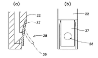
図5に示される薬液注入ポート10での閉鎖手段は、薬液排出口28を塞ぐ閉鎖フィルム30である。薬液注入ポート10は、薬液注入口24と除菌フィルター16とを備える、いわゆるコマ形フィルターと呼ばれる本体部材20と、本体部材20の下方に接続された筒状部材22と、薬液注入口24を覆うキャップ26とで構成されている。そして、筒状部材22が薬液容器12内に挿入され、薬液容器12(図中省略)の縁部13と溶着又は接着により気密に固着される。
【0040】
この薬液注入ポート10において、薬液排出口28は筒状部材22の最下部側壁に設けられ、閉鎖フィルム30によって塞がれている。閉鎖フィルム30は、薬液排出口28の回りに溶着又は接着されているのであるが、その溶着又は接着の強さは、薬液注入口24から薬液が注入された時に受ける薬液注入圧によって剥離する程度とされている。このため、使用前には、閉鎖フィルム30よって薬液排出口28が塞がれているので、薬液容器12中の薬液が薬液注入ポート10内に進入することがなく、混注操作を行えば、閉鎖フィルム30が剥離して自動的に薬液排出口28が開放され、注入された薬液が薬液容器12内に入って、すでに薬液容器12内に収容されていた薬液と混合される。
【0041】
薬液注入圧によって剥離する程度の強さで薬液排出口28をフィルムで塞ぐ、この実施態様では、薬液排出口28の位置や形状は特に限定されない。図6は、薬液排出口28を筒状部材22の底部に設けた例を示す。あるいは、図1に示されるのと同様の構成で、出口部材18と閉鎖フィルム30との固着強さを、剥がれ易いように適切に制御することもできる。剥がれた閉鎖フィルム30が薬液容器12内に落下しないように、一部は剥離しないままに残ることが好ましい。
【0042】
図7に示される薬液注入ポート10は、本発明の好ましい別の実施態様を示し、通液路36を塞ぐ閉鎖手段として、一端が閉じられた筒状のフィルムが採用されている。すなわち、筒状フィルム52の開口した一端48が、薬液排出口28の回りに固着されて薬液排出口28を覆い、他の一端50は、薬液注入圧によって破壊される程度の強さで、その内面どうしが溶着されて閉じられている。したがって、薬液注入口24から薬液が注入されると、その薬液注入圧によって、筒状フィルム52の閉じられた一端50が開放され、注入された薬液は薬液容器12(図2参照)内に投入される。筒状フィルム52の開口した一端48を、薬液排出口28の回りに固着する手段は限定されないが、溶着、接着、バンド締めなどによるのが好ましい。また、他の一端50の溶着は、その内面どうしを直接溶着してもよいし、異種のフィルムを介在させた溶着でもよい。なお、通液路36を塞ぐフィルムは、通液路内に設けられてもよい。
【0043】
図8は、閉鎖手段が薬液排出口28を塞ぐ弾性部材である一例を示している。筒状部材22の最下部側面に設けられた薬液排出口28を、ゴム状弾性体のチューブ29が覆い、薬液容器12内の薬液が薬液注入ポート10に進入するのを妨げている。薬液注入口24から混注用の薬液が注入されると、その注入圧によってチューブ29が膨らみ、筒状部材22との間に間隙が生じて薬液排出口28が開放される。注入が止まれば、チューブ29は再び元の位置に戻って薬液排出口28を塞ぐので、チューブ29は逆止弁の役割を果たしている。
【0044】
図9に示される他の一例では、薬液排出口28を塞ぐ弾性部材として板ばね37が用いられている。薬液注入圧を受けて板ばね37が外側に撓み、筒状部材22との間に間隙が生じて薬液排出口28が開放される。
【0045】
また、図10に示される薬液注入ポート10は、図1に示される薬液注入ポート10と類似しているが、薬液排出口28を塞ぐ閉鎖フィルム30の代わりに、弾性部材としての板ばね37が用いられている。弾性部材としては、上述の例示に限定されず、コイルばねなどを利用してもよい。
【0046】
図11に示される薬液注入ポート10では、薬液排出口28内に閉鎖部材58を挿入することによって、通液路36を塞ぐ手段が採用されている。すなわち、断面が円形とされた薬液排出口28内に、略球状の閉鎖部材58を挿入することによって薬液排出口28を塞いでいるのであるが、閉鎖部材58は、薬液注入圧によって薬液排出口28から離脱する程度の強さで薬液排出口28内に係留されている。このため、薬液注入口24から薬液が注入されると、その薬液注入圧によって閉鎖部材58が薬液排出口28から離脱して放出され、通液路26が開放される。閉鎖部材58の形状は、薬液排出口28の形状に合わせて適切に選定されるが、断面が円形とされた薬液排出口28には、球状、円柱状、有底円錐状などが適している。そして適度の弾性を備えているのが好ましい。
【0047】
本例では,薬液排出口28の下に捕捉部材54が装着されていて、薬液注入圧によって離脱・放出される閉鎖部材58を受けとめ、薬液容器12(図2参照)内に落下するのを防いでいる。薬液容器12の薬液排出ポート60(図2参照)の入口を、落下した閉鎖部材58が塞ぐトラブルなどの発生を避けるためである。捕捉部材54には、閉鎖部材58より狭い幅の、略長方形の開口部56が設けられているので、閉鎖部材58を受けとめても、薬液はその両脇を通ることができる。
【0048】
図12に示される薬液注入ポート10では、薬液注入圧を二次的に高めるための圧縮手段が設けられている。入口部材14の上部の筒状部内面に沿ってスライド自在とされたスライド部材66が設けられ、このスライド部材66に設けられた薬液注入口24は、ゴム状弾性体からなり注射針が穿刺可能な栓体62で密閉されていて、栓体62と除菌フィルター16との間に薬液溜室64が形成されている。混注する時には、栓体62を刺通する注射針を用いてまず薬液溜室64に薬液を注入し、次いで、スライド部材66を下降させて薬液溜室64を圧縮する。すると、薬液溜室64内に一旦溜められていた薬液は、薬液注入口24側が密閉されているため、圧縮圧を強く受けて除菌フィルター16側に流れ出す。そして、除菌フィルター16の下方に設けられた閉鎖手段に、その強い圧縮圧力を伝えて閉鎖手段を開放させる。本例の閉鎖手段は薬液排出口28を塞ぐ閉鎖フィルム30であり、出口部材18の円環状突起44と閉鎖フィルム30との溶着が、薬液注入圧を受けて剥がれるようにされている。なお、使用する前にスライド部材66が下降することを防ぐためのインターロック機構を備えてもよい。
【0049】
薬液注入圧を二次的に高めるこの工夫は、薬液注入圧によって開放される閉鎖手段が備えられた薬液注入ポート10に用いられて、閉鎖手段の開放をより確実にするものであり、比較的注入圧が低い、注射針による薬液注入の場合に特に有効である。併用される閉鎖手段としては、薬液注入圧によって開放されるものであればよく、図1〜図11などを用いてすでに説明した閉鎖手段などを含み、特に限定されない。
【0050】
図13と図14は、薬液注入口24と除菌フィルター16とを備えた本体部材20の上下動作によって、閉鎖部材を移動もしくは破壊させ、閉鎖手段を開放する例を示している。すなわち、図13に示される薬液注入ポート10は、閉鎖部材を破壊させる機能を備えた一例であるが、本体部材20とスライド部材23とが一体となって、筒状部材22内を上下動できるようにされ、ロケット針のように、スライド部材23の尖鋭な先端部に薬液排出口28が設けられている。また、筒状部材22の底部に設けられた開口部39が閉鎖フィルム30で塞がれている。このため、本体部材20に被せられたキャップ26を下方に押せば、本体部材20と共にスライド部材23が下降し、その尖鋭な先端部が閉鎖フィルム30を突き破り、通液路36と薬液容器12とが連通するようになる。
【0051】
一方、図14に示される薬液注入ポート10は、閉鎖部材を移動させる機能を備えている。この薬液注入ポート10には、図11に示される薬液注入ポート10と同様に、断面が円形とされた薬液排出口28内に、略球状の閉鎖部材58が挿入されて薬液排出口28を塞いでいる。薬液排出口28は筒状部材22の底部に設けられているので、キャップ26を下方に押して本体部材20と共にスライド部材23を下降させれば、スライド部材23の下端が閉鎖部材58に突き当たり、薬液排出口28から押し除くことになり、通液路36と薬液容器12とが連通するようになる。
【0052】
図15に示される薬液注入ポート10では、入口部材14と除菌フィルター16と出口部材18とからなる本体部材20が、筒状部材22の内面に沿って上下にスライド自在とされている。そして、出口部材18の下垂部68の側面に設けられた薬液排出口28は、本体部材20が上方にある時はスライド面74によって塞がれ、下方にスライドされた時はスライド面74から離れて開放されるようにされている。使用(混注)前には薬液排出口28が閉鎖されているため、薬液容器12(図2参照)内に収容されている薬液が薬液注入ポート10に進入することがなく、混注する時には、本体部材20を下降させ、キャップ26を外し、シリンジなどで薬液注入口24から薬液を注入すればよい。なお、使用する前に本体部材20が下降することを防ぐためのインターロック機構を備えてもよい。
【0053】
図16、図18、図19、図20のそれぞれに示される薬液注入ポート10は、いずれも、本体部材20の回転動作によって、閉鎖手段を開放する機能を備えている。図16に示される薬液注入ポート10では、薬液容器12(図中省略)と連結される出口部材25の回りを、本体部材20と筒状部材22とが一体となって回転可能とされている。また、出口部材25には薬液排出口としての多数の孔28が設けられ、その上を馬蹄形状の閉鎖フィルム30が覆って塞いでいる。そして、閉鎖フィルム30の端に形成されたリング31が、本体部材20の底部の中央から周辺部へと伸びる引っ掛け用の爪33に係止されている。このため、本体部材20と筒状部材22とを矢印の向きに回転させると、爪33がリング31を引っ掛けたまま回転することになって、閉鎖フィルム30がリング31側の端から順に捲られ、薬液排出口28が開放される。
【0054】
図18に示される薬液注入ポート10では、薬液排出口28が斜めに張った閉鎖フィルム30で塞がれ、本体部材20の底部の、フィルム30が離れている側に、ピン35が下向きにして備えられている。このため、本体部材20を回転させると、ピン35が閉鎖フィルム30に突き当たり、閉鎖フィルム30を破って薬液排出口28が開放されることになる。
【0055】
また、図19に示される薬液注入ポート10では、入口部材14と除菌フィルター16と出口部材18とからなる本体部材20が、筒状部材22の内面に沿って回動自在とされている。そして、出口部材18の下垂部68の側面には薬液排出口28が設けられ、薬液排出口28が回動して接する摺動面76の一部には、外部に通じる開口部78が設けられている。したがって、使用前には、薬液排出口28が摺動面76によって蓋されるように回動の位置を決めておき、使用するときには、本体部材20を回動させて、薬液排出口28と開口部78とを一致させればよい。使用(混注)前には薬液排出口28が閉鎖されているため、薬液容器12(図2参照)内に収容されている薬液が薬液注入ポート10に進入することがなく、混注する時には、本体部材20を回動させ、キャップ26を外し、シリンジなどで薬液注入口24から薬液を注入すればよい。
【0056】
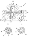
また、図20に示される薬液注入ポート10では、出口部材18の下方にカップ形の底部材80が設けられており、出口部材18とともに、幅広の、比較的広くされた通液路36を形成している。そして、この通液路36部分には、本体部材20に係着されて本体部材20と共に回動自在とされた内蓋部材82が備えられている。また、内蓋部材82の下面に接して二個の薬液排出口28が、底部材80に、本体部材20の回動中心軸92から離れて設けられている。
【0057】
図21に示されるように、内蓋部材82は略亜鈴状の平板部94から2本の棒状柱96が立ち上がる形状とされていて、平板部94は略円形の2個の盲部分88を両側に有し、その中央部にはクビレ90が形成されている。底部材80に設けられた薬液排出口28は、使用前にはこの盲部分88によって蓋されているが、使用する時には内蓋部材82を90°回転させて盲部分88を移動させることにより、薬液排出口28が開放される。内蓋部材82の2本の棒状柱96は、出口部材18に設けられた2個の孔98に挿入されて係着され、筒状部材22と一体化された本体部材20を回転するのに伴なって回転する。
【0058】
この実施態様において、薬液排出口28を覆う内蓋部材82の盲部分88の下面と、底部材80の上面とを、本体部材20の手動による回動によって容易に剥がせる程度の強さで溶着又は接着してもよい。また、内蓋部材82の平板部94を円形とし、薬液排出口28と連通するための2個の開口部を設けてもよい。あるいは、筒状部材22と底部材80とを一体化して、本体部材20と内蓋部材82だけが回動できるようにされてもよい。あるいは、薬液排出口28を3個以上設けるとともに、これらの全ての薬液排出口28を開閉できる内蓋部材82を製作することもできる。
【0059】
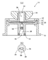
図22に示される薬液注入ポート10は、閉鎖手段として、通液路36を塞ぐ開閉弁100が用いられる一例であり、図23は、この薬液注入ポート10に用いられる操作部材102を示している。開閉弁100は、通液路36の断面と同形状の円盤状とされ、筒状部材22の側部を貫通して連結される操作部材102によって、バタフライ弁と同様に回転操作される。操作部材102の端部には扁平な摘み部分104が形成されているので、その向きによって開閉弁100の開閉状態を確認できるので、間違いなく確実に開閉操作を行える。なお、本例の薬液注入ポート10では、図24に示されるような、球状の開閉弁101を用いることができる。開閉弁101には、その球状の中心を貫く通液孔106が設けられているので、90°の回転によって、通液路36を開閉することができる。
【0060】
図25に示される薬液注入ポート10も、閉鎖手段として、通液路36を塞ぐ開閉弁が用いられる他の一例であり、図26は、この薬液注入ポート10に用いられる操作部材103を示している。本例では、通液路36を横切る操作部材103のスライドによって開かれる開閉弁が用いられ、短冊状の操作部材103の略先端部に円形の通液孔108が設けられている。使用(混注)前には、通液孔108よりさらに先端側にある平板部110で通液路36を塞いでいて、使用する時には操作部材103を押し込み、通液孔108を通液路36に合わせることによって通液路36を開放する。
【0061】
また、図27に示される薬液注入ポート10では、薬液排出口28を塞ぐ隔壁110を、筒状部材22の側部を貫通する操作部材112の操作によって破り、通液路36を開放する手段が採用されている。すなわち、通液路36の側部の、薬液排出口28が形成される部分が薄い隔壁110によって閉じられており、この隔壁110を操作部材112の先端で突き破ろうとするものである。操作部材112の先端は鋭く尖って隔壁110に直面し、筒状部材22から突出する後端を押し込むことによって、隔壁110を簡単に破ることができる。なお、細菌などの混入を避けるため、操作部材112の後端付近は保護フィルム114で覆われている。
【0062】
次ぎに、本発明に係わる薬液容器12について詳細に説明する。その一つの実施態様では、上述した幾つかの薬液注入ポート10が備えられる。薬液注入ポート10を取り付ける位置や手段は特に限定されない。薬液容器12の端部にでも中央部にでも取り付けることができる。また、薬液注入ポート10を薬液容器12本体に固着するには、溶着や接着などによるのが好ましい。
【0063】
図28は、本発明に係わる薬液容器12の別の実施態様を示している。すなわち、薬液容器12は、除菌フィルター16(図中省略)付きの薬液注入ポート10と薬液排出ポート60を備え、表裏2枚のシートからなる袋状であって、薬液注入ポート10が備えられた注入室63と、薬液が予め収容される収容室65とが、表裏2枚のシート間を容易に剥離できる程度の強さで溶着又は接着して形成した弱シール部61によって分離されている。収容室65に収容された薬液は、弱シール部61によって薬液注入ポート10内に進入するのが妨げられるので、除菌フィルター16の変質や目詰まりなどが生じず、除菌フィルター16の性能が正常に維持される。そして、使用する時には、弱シール部61を剥離して注入室63と収容室65とを連通させることにより、容易に混注することができる。
【0064】
弱シール部61を剥離する手段は特に限定されないが、薬液注入圧によって自動的に剥離されるのが好ましい。したがって、本発明の特に有用な実施態様では、薬液注入圧を受ければ剥離する程度の強さで、弱シール部61が溶着又は接着される。図29に示される薬液容器12では、薬液注入ポート10が薬液容器12の角部にあり、弱シール部61を短くして、注入室63を狭くすることができる。このため、弱シール部61に薬液注入圧が強く作用するようになり、より確実に剥離するようになる。
【0065】
弱シール部61を剥離するために、弱シール部61の表面又は裏面の、少なくともどちらかに、摘んで引くための突起を設けることも有効である。図30に示される弱シール部61には、表裏それぞれに突起67が設けられている。すなわち、これらの突起67は、表シート69と裏シート71を弛ませて、それぞれを対向的に二つ折りすることによって形成されている。二つの突起67を摘んで引っ張れば、弱シール部61は容易に剥離して表シート69と裏シート71とに解離し、注入室63と収容室65とが連通する。
【0066】
また、図31に示される弱シール部61には、表面側にだけ突起67が設けられている。突起67は表シート69や裏シート71とは別部材であり、表シート69に溶着又は接着などによって固着されている。突起67の形状や材質は特に限定されないが、表シート69との固着が容易で、収納に便利なように折り畳むことのできる、プラスチックシートが好ましく用いられる。
【0067】
以上、本発明に係わる薬液注入ポート及びこれを装着した薬液容器について詳細に説明してきたが、本発明は上述の引用・例示に限定されず、薬液注入ポートの形状や構成、入口部材や出口部材や底部材やキャップなどの材質、除菌フィルターの種類や構成、薬液注入ポートを薬液容器へ装着する方法、薬液容器の種類や形状、薬液の種類や量、滅菌方法などにつき、本発明の趣旨を逸脱しない範囲で、当業者の知識に基づき種々なる改良、修正、変化を加えた態様で実施し得るものである。
【0068】
例えば、薬液容器の形は長方形に限らず楕円形などでもよい。また、薬液注入ポートの取り付け位置は、縁部に限らず側面であってもよい。また、弱シール部の剥離を、収容室を介して強制的に圧力を加えることで行ってもよい。また、図16に示される薬液注入ポート10と類似した構造として、本体部材20の回転ではなく、本体部材20の引き上げによって閉鎖フィルム30を剥がすようにしてもよい。
【0069】
【発明の効果】
本発明に係わる薬液注入ポートによれば、除菌フィルターを備えているので、混注のために注入される薬液に細菌などが混入していても、除菌フィルターによって除去されて薬液容器に投入されるので安全である。また、除菌フィルター以降の通液路を塞ぐ閉塞手段が備えられているので、使用前に、薬液容器に収容される薬液が薬液注入ポートへ進入することがなく、除菌フィルターの変質や目詰まりなどが生じないで、除菌フィルターの性能が正常に維持される。そして、閉鎖手段は容易に開放されるので、簡便な操作で使用(混注)できて便利である。
【0070】
さらに、薬液注入圧で開放される閉鎖手段とすることにより、薬液注入だけで、他の操作を必要とせずに、簡単に混注できる薬液注入ポートを得ることができる。
【0071】
またさらに、本体部材の移動によって開放される閉鎖手段とすることにより、閉鎖手段を開放するための新たな部材を設けることなく、簡略化された構造の薬液注入ポートを得ることができる。
【0072】
またさらに、薬液注入ポートの側壁を貫通する操作部材の操作によって開かれる開閉弁を閉鎖手段とすることにより、閉鎖手段の開放を確実に実行できる薬液注入ポートを得ることができる。
【0073】
また、本発明に係わる、薬液注入ポートを備えた薬液容器によれば、簡単な操作で混注を行うことができ、細菌などを含まなくて安全な混合薬液が得られるので、敗血症やエンドトキシンショックなどの副作用を全く心配せずに、安心して患者に投与できるようになる。
【図面の簡単な説明】
【図1】本発明に係わる薬液注入ポートの一例を示す縦断面図である。
【図2】本発明に係わる薬液容器の一例を示す正面図である。
【図3】本発明に係わり、図1に示される出口部材の詳細を示し、同図(a)は上面図、同図(b)は縦断面図、同図(c)は裏面図である。
【図4】本発明に係わり、図1に示される閉鎖フィルムに設けられる弱所の形状を例示し、同図(a)は十字形、同図(b)は円形、同図(c)は舌状を示す。
【図5】本発明に係わる薬液注入ポートの他の一例を示し、同図(a)は縦断面図、同図(b)は、薬液排出口付近を示す正面図である。
【図6】本発明に係わり、薬液排出口付近を示す縦断面図である。
【図7】本発明に係わる薬液注入ポートの他の一例を示す縦断面図である。
【図8】本発明に係わる薬液注入ポートの他の一例を示し、同図(a)は縦断面図、同図(b)は、薬液排出口付近を示す正面図である。
【図9】本発明に係わり、薬液排出口付近を示し、同図(a)は縦断面図、同図(b)は正面図である。
【図10】本発明に係わる薬液注入ポートの他の一例を示す縦断面図である。
【図11】本発明に係わる薬液注入ポートの他の一例を示し、同図(a)は全体の縦断面図、同図(b)は捕捉部材周辺の底面図である。
【図12】本発明に係わる薬液注入ポートの他の一例を示す縦断面図である。
【図13】本発明に係わる薬液注入ポートの他の一例を示す縦断面図である。
【図14】本発明に係わる薬液注入ポートの他の一例を示す縦断面図である。
【図15】本発明に係わる薬液注入ポートの他の一例を示す縦断面図である。
【図16】本発明に係わる薬液注入ポートの他の一例を示す縦断面図である。
【図17】本発明に係わり、図16に示される薬液注入ポートの出口部材を示す上面図である。
【図18】本発明に係わる薬液注入ポートの他の一例を示す縦断面図である。
【図19】本発明に係わる薬液注入ポートの他の一例を示し、同図(a)は全体の縦断面図、同図(b)と同図(c)はA−A断面図であり、同図(b)は薬液排出口が閉じた状態、同図(c)は薬液排出口が開いた状態を示す。
【図20】本発明に係わる薬液注入ポートの他の一例を示す縦断面図である。
【図21】本発明に係わり、図20におけるB−B断面図であり、同図(b)は薬液排出口が閉じた状態、同図(c)は薬液排出口が開いた状態を示す。
【図22】本発明に係わる薬液注入ポートの他の一例を示す縦断面図である。
【図23】本発明に係わり、図22における操作部材の一例を示す上面図である。
【図24】本発明に係わり、図22における操作部材の他の一例を示す斜視図である。
【図25】本発明に係わる薬液注入ポートの他の一例を示す縦断面図である。
【図26】本発明に係わり、図25における操作部材の一例を示す上面図である。
【図27】本発明に係わる薬液注入ポートの他の一例を示す縦断面図である。
【図28】本発明に係わる薬液容器の他の一例を示す正面図である。
【図29】本発明に係わる薬液容器の他の一例を示す正面図である。
【図30】本発明に係わり、弱シール部の一例を示す断面図である。
【図31】本発明に係わり、弱シール部の他の一例を示す断面図である。
【符号の説明】
10:薬液注入ポート
12:薬液容器
13:薬液容器の縁部
14:入口部材
16:除菌フィルター
18、25:出口部材
20:本体部材
22:筒状部材
23:スライド部材
24:薬液注入口
26:キャップ
28:薬液排出口
29:チューブ
30:閉鎖フィルム
31:リング
32、34:フランジ
33:爪
35:ピン
36:通液路
37:板ばね
38、40:溝
39:開口部
42、44:突起
46:弱所
48:筒状フィルムの一端
50:筒状フィルムの他の一端
52:筒状フィルム
54:捕捉部材
56、78、84:開口部
58:閉鎖部材
60:薬液排出ポート
61:弱シール部
62:栓体
63:注入室
64:薬液溜室
65:収容室
66:スライド部材
67:突起
68:下垂部
69:表シート
70、72、86:O−リング
71:裏シート
74:スライド面
76:摺動面
80:底部材
82:内蓋部材
88:盲部分
90:クビレ
92:回転軸
94:平板部
96:棒状柱
98:孔
100:開閉弁
102、103、112:操作部材
104:摘み部分
106、108:通液孔
110:隔壁
114:保護フィルム[0001]
BACKGROUND OF THE INVENTION
The present invention relates to a chemical solution injection port for aseptically and simply performing a mixed injection of chemical solutions, specifically, a mixed injection of another chemical solution into an injection solution such as an infusion solution, and a chemical solution provided with the chemical solution injection port. Concerning the container.
[0002]
[Prior art]
In clinical settings, it is frequently used to administer a plurality of types of drug solutions to a patient at the same time. For example, when a vitamin preparation or the like is to be injected into a vein, the vitamin preparation is altered by heat. Therefore, the vitamin preparation cannot be stored in a chemical container such as an infusion pack and subjected to high-pressure steam sterilization in advance. For this reason, at the time of use, it is necessary to inject and mix (this is referred to as mixed injection) into a chemical solution container in which another chemical solution is previously stored, and to mix in the chemical solution container.
[0003]
In the case of mixing the above chemical solution into the chemical solution container, conventionally, a method in which an injection needle is inserted into the rubber stopper of the chemical solution discharge port of the chemical solution container has been adopted, but in such a method, sterility during the mixed injection operation has been adopted. It was difficult to ensure. When microorganisms (bacteria) are mixed from the outside during the mixed injection operation, the microorganisms propagate in the mixed injection solution during the period when this mixed injection solution is administered to the patient. In particular, when the injection solution is an infusion solution for nutritional supplementation such as a high calorie infusion solution, there is a risk that microorganisms will propagate during the administration period even if a small amount is mixed. In the later stage of administration, a large amount of microorganisms may be injected into the patient simultaneously with the infusion. Patients who receive such mixed injections cause serious side effects such as sepsis and endotoxin shock. Therefore, it is necessary to ensure sterility at the time of mixed injection operation, taking into account patient safety.
[0004]
[Problems to be solved by the invention]
It is an object of the present invention to provide a chemical liquid injection port that can inject a chemical liquid aseptically, has a small number of parts, and has a structure that is smaller and simpler than the prior art, and a chemical liquid container including the chemical liquid injection port. To do.
[0005]
[Means for Solving the Problems]
The gist of the chemical liquid injection port according to the present invention is that the chemical liquid injection port formed at the upper end, the chemical liquid discharge port formed at the lower end connectable to the chemical liquid container, and the chemical liquid injection port A liquid passage communicating with the chemical solution outlet, a sterilization filter provided in the liquid passage, and a closing means provided so as to close and open the liquid passage under the sterilization filter. It is to prepare. In particular, the closing means is opened by a chemical liquid injection pressure injected from the chemical liquid injection port, and the closing means is a member for closing the chemical liquid discharge port, and the chemical injection pressure injected from the chemical liquid injection port Destroyed It is to be opened.
[0006]
In particular, the chemical solution injection port employs a closing means that is opened by the chemical solution injection pressure injected from the chemical solution injection port.
[0007]
Further, the closing means is a film for closing the liquid passage, and this film is provided with a weak point to be broken by the chemical liquid injection pressure.
[0008]
Alternatively, the closing means is a film that closes the chemical solution outlet, and this film is welded or adhered around the chemical solution outlet to cover the chemical solution outlet, and the strength of the welding or adhesion depends on the chemical injection pressure. It is supposed to be peeled off.
[0009]
Alternatively, the closing means is a cylindrical film that closes the chemical solution discharge port, one end of which is open and fixed around the chemical solution discharge port to cover the chemical solution discharge port, and the other end is the chemical solution injection pressure. The inner surfaces are closed by being welded or adhered to each other with such a strength that can be broken by the above.
[0010]
Alternatively, the closing means is an elastic member that closes the chemical solution outlet, and the elastic member is deformed by receiving a chemical injection pressure, whereby the chemical solution outlet is opened.
[0011]
Alternatively, the closing means is a closing member inserted into the chemical solution discharge port, and the closing member is moored in the chemical solution discharge port with such a strength that it can be separated from the chemical solution discharge port by the chemical solution injection pressure. It is in.
[0012]
Still further, the closing means is provided with means for capturing the closing member that is detached from the chemical solution outlet when the chemical solution is injected.
[0013]
Further, in the chemical liquid injection port provided with these closing means, the chemical liquid injection port is sealed with a rubber-like elastic body that can be punctured by the injection needle, so that a chemical liquid reservoir is provided between the chemical liquid injection port and the sterilization filter. In addition, there is provided a compression means for compressing the internal volume of the chemical liquid storage chamber into liquid nectar, and once the chemical liquid has been injected into the chemical liquid storage chamber, the chemical injection pressure is increased by the compression means and pumped to the sterilization filter side. It is to be made to do.
[0014]
In particular, the chemical solution injection port employs a closing means that is opened by the movement of the main body member including the chemical solution injection port and the sterilization filter.
[0015]
Furthermore, in such a closing means, the closing means is opened by causing the closing member to move or break by the vertical movement of the main body member.
[0016]
Alternatively, in this closing means, the main body member is slidable up and down, and when the main body member is at the upper side, the chemical solution discharge port provided on the side surface of the main body member is closed by the slide surface. When it is slid, it is to be released away from the slide surface.
[0017]
Alternatively, in the closing means, the closing means is opened by causing the closing member to move or break by the rotation of the main body member.
[0018]
Alternatively, in this closing means, the main body member is rotatable, a chemical solution discharge port is provided on the side surface of the hanging part of the main body member, and a part of the rotating sliding surface with which the chemical solution discharge port is in contact with the outside There exists in the opening part which leads to.
[0019]
Alternatively, in the closing means, an inner lid member that is engaged with the main body member and is rotatable with the main body member is provided below the main body member, and the inner lid member has a relatively wide fluid passage. The at least two chemical solution discharge ports are provided in contact with the lower surface of the inner lid member so as to be separated from the rotation center axis of the main body member, while the inner cover member has a chemical solution discharge port. There exists a blind part which covers from an inner side, and it is set as the shape by which a chemical | medical solution discharge port is open | released by rotation of an inner cover member.
[0020]
In particular, in such a chemical liquid injection port, the closing means is an open / close valve that closes the liquid passage, and the open / close valve is opened by operating an operation member that penetrates the side wall of the chemical liquid injection port and is connected to the open / close valve. .
[0021]
Further, in the closing means, the on-off valve is opened by the rotation of the operation member.
[0022]
Alternatively, in this closing means, the on-off valve is opened by a slide across the liquid passage of the operation member.
[0023]
In particular, in such a chemical liquid injection port, the closing means is a partition wall that closes the chemical liquid discharge port, and is broken and opened by operation of an operation member that penetrates the side wall of the chemical liquid injection port.
[0024]
Moreover, the gist of the chemical solution container provided with the chemical solution injection port according to the present invention is to include the chemical solution injection port described above.
[0025]
Further, according to the present invention, the other aspect of the chemical liquid container having the chemical liquid injection port includes a chemical liquid injection port and a chemical liquid discharge port, and is a bag-shaped chemical liquid container composed of two sheets on the front and back sides, The injection chamber provided with the chemical solution injection port and the storage chamber in which the chemical solution is stored in advance are separated by a weak seal portion formed by welding or bonding with such a strength that the two sheets can be easily separated from each other. There is in being.
[0026]
In particular, this weak seal portion is made to receive the chemical injection pressure injected from the chemical injection port and peel it off so that the injection chamber communicates with the storage chamber.
[0027]
Alternatively, in particular, a protrusion is provided on at least one of the front surface and the back surface of the weak seal portion, and the weak seal portion is peeled off into two front and back surfaces by picking and pulling the protrusion.
[0028]
DETAILED DESCRIPTION OF THE INVENTION
Next, embodiments of the chemical solution injection port and the chemical solution container according to the present invention will be described in detail with reference to the drawings.
[0029]
FIG. 1 shows a preferred example of a chemical
[0030]
In the present invention, the upper side means the side where the chemical
[0031]
The bottom surface of the
[0032]
The
[0033]
In the
[0034]
According to the
[0035]
The
[0036]
The material of the
[0037]
The
[0038]
The chemical
[0039]
The closing means in the chemical
[0040]
In the chemical
[0041]
In this embodiment in which the
[0042]
The
[0043]
FIG. 8 shows an example in which the closing means is an elastic member that closes the
[0044]
In another example shown in FIG. 9, a
[0045]
10 is similar to the
[0046]
In the chemical
[0047]
In this example, a
[0048]
The
[0049]
This device for secondarily increasing the chemical solution injection pressure is used for the chemical
[0050]
FIG. 13 and FIG. 14 show an example in which the closing member is opened by moving or destroying the closing member by the vertical movement of the
[0051]
On the other hand, the
[0052]
In the chemical
[0053]
16, 18, 19, and 20 each have a function of opening the closing means by the rotation of the
[0054]
In the chemical
[0055]
In addition, in the chemical
[0056]
Further, in the chemical
[0057]
As shown in FIG. 21, the
[0058]
In this embodiment, the lower surface of the
[0059]
The
[0060]
The chemical
[0061]
Further, in the chemical
[0062]
Next, the
[0063]
FIG. 28 shows another embodiment of the
[0064]
The means for peeling the
[0065]
In order to peel off the
[0066]
Further, the
[0067]
As described above, the chemical liquid injection port according to the present invention and the chemical liquid container equipped with the chemical liquid injection port have been described in detail. However, the present invention is not limited to the above-mentioned citations and examples, and the shape and configuration of the chemical liquid injection port, the inlet member and the outlet member The purpose of the present invention is the material such as the bottom member and cap, the type and configuration of the sterilization filter, the method of mounting the chemical solution injection port on the chemical solution container, the type and shape of the chemical solution container, the type and amount of the chemical solution, the sterilization method, etc. The present invention can be carried out in a mode in which various improvements, modifications, and changes are added based on the knowledge of those skilled in the art without departing from the scope of the present invention.
[0068]
For example, the shape of the chemical solution container is not limited to a rectangle but may be an ellipse. Moreover, the attachment position of the chemical solution injection port is not limited to the edge portion but may be a side surface. Further, the weak seal part may be peeled off by forcibly applying pressure through the accommodation chamber. Moreover, as a structure similar to the chemical
[0069]
【The invention's effect】
According to the chemical solution injection port according to the present invention, since the sterilization filter is provided, even if bacteria or the like is mixed in the chemical solution injected for mixed injection, it is removed by the sterilization filter and put into the chemical solution container. So it is safe. In addition, since a blocking means for closing the liquid passage after the sterilization filter is provided, the chemical liquid stored in the chemical liquid container does not enter the chemical liquid injection port before use, and the sterilization filter is not altered or removed. The performance of the sterilization filter is maintained normally without clogging. And since a closing means is open | released easily, it can be used (mixed injection) by simple operation, and is convenient.
[0070]
Furthermore, by using the closing means that is opened by the chemical liquid injection pressure, it is possible to obtain a chemical liquid injection port that can be simply mixed and injected by only injecting the chemical liquid without any other operation.
[0071]
Furthermore, by using the closing means that is opened by the movement of the main body member, a chemical injection port having a simplified structure can be obtained without providing a new member for opening the closing means.
[0072]
Furthermore, by using the on-off valve that is opened by operating the operation member that penetrates the side wall of the chemical liquid injection port as the closing means, a chemical liquid injection port that can reliably execute the opening of the closing means can be obtained.
[0073]
Further, according to the chemical container having the chemical injection port according to the present invention, it is possible to perform mixed injection by a simple operation, and a safe mixed chemical liquid that does not contain bacteria can be obtained, so that sepsis, endotoxin shock, etc. The patient can be safely administered without worrying about the side effects.
[Brief description of the drawings]
FIG. 1 is a longitudinal sectional view showing an example of a chemical liquid injection port according to the present invention.
FIG. 2 is a front view showing an example of a chemical solution container according to the present invention.
3 shows details of the outlet member shown in FIG. 1 according to the present invention, wherein FIG. 3A is a top view, FIG. 3B is a longitudinal sectional view, and FIG. .
4 relates to the present invention and exemplifies the shape of a weak point provided in the closure film shown in FIG. 1, wherein FIG. 4 (a) is a cross shape, FIG. 4 (b) is a circle, and FIG. Tongue is shown.
5A and 5B show another example of a chemical solution injection port according to the present invention, where FIG. 5A is a longitudinal sectional view, and FIG. 5B is a front view showing the vicinity of a chemical solution discharge port.
FIG. 6 is a longitudinal sectional view showing the vicinity of a chemical solution discharge port according to the present invention.
FIG. 7 is a longitudinal sectional view showing another example of a chemical liquid injection port according to the present invention.
8A and 8B show another example of a chemical liquid injection port according to the present invention, where FIG. 8A is a longitudinal sectional view, and FIG. 8B is a front view showing the vicinity of a chemical liquid discharge port.
FIG. 9 shows the vicinity of the chemical solution outlet according to the present invention, wherein FIG. 9 (a) is a longitudinal sectional view and FIG. 9 (b) is a front view.
FIG. 10 is a longitudinal sectional view showing another example of the chemical liquid injection port according to the present invention.
11A and 11B show another example of the chemical solution injection port according to the present invention, where FIG. 11A is a longitudinal sectional view of the whole, and FIG. 11B is a bottom view of the periphery of the capturing member.
FIG. 12 is a longitudinal sectional view showing another example of a chemical liquid injection port according to the present invention.
FIG. 13 is a longitudinal sectional view showing another example of a chemical liquid injection port according to the present invention.
FIG. 14 is a longitudinal sectional view showing another example of a chemical liquid injection port according to the present invention.
FIG. 15 is a longitudinal sectional view showing another example of a chemical liquid injection port according to the present invention.
FIG. 16 is a longitudinal sectional view showing another example of a chemical liquid injection port according to the present invention.
17 is a top view showing an outlet member of the chemical liquid injection port shown in FIG. 16 according to the present invention.
FIG. 18 is a longitudinal sectional view showing another example of a chemical liquid injection port according to the present invention.
FIG. 19 shows another example of the chemical solution injection port according to the present invention, wherein FIG. 19 (a) is an overall longitudinal sectional view, FIG. 19 (b) and FIG. FIG. 4B shows a state in which the chemical solution discharge port is closed, and FIG. 5C shows a state in which the chemical solution discharge port is opened.
20 is a longitudinal sectional view showing another example of a chemical liquid injection port according to the present invention. FIG.
FIG. 21 is a cross-sectional view taken along the line BB in FIG. 20 according to the present invention, where FIG. 21 (b) shows a state in which the chemical solution discharge port is closed, and FIG. 21 (c) shows a state in which the chemical solution discharge port is open.
FIG. 22 is a longitudinal sectional view showing another example of the chemical liquid injection port according to the present invention.
23 is a top view illustrating an example of the operation member in FIG. 22 according to the present invention.
24 is a perspective view showing another example of the operation member in FIG. 22 according to the present invention.
FIG. 25 is a longitudinal sectional view showing another example of a chemical liquid injection port according to the present invention.
26 is a top view showing an example of the operation member in FIG. 25 according to the present invention.
FIG. 27 is a longitudinal sectional view showing another example of a chemical liquid injection port according to the present invention.
FIG. 28 is a front view showing another example of the chemical container according to the present invention.
FIG. 29 is a front view showing another example of a chemical solution container according to the present invention.
FIG. 30 is a cross-sectional view showing an example of a weak seal portion according to the present invention.
FIG. 31 is a cross-sectional view showing another example of the weak seal portion according to the present invention.
[Explanation of symbols]
10: Chemical solution injection port
12: Chemical container
13: Edge of chemical container
14: Entrance member
16: Sanitization filter
18, 25: outlet member
20: Main body member
22: Cylindrical member
23: Slide member
24: Chemical solution inlet
26: Cap
28: Chemical solution outlet
29: Tube
30: Closure film
31: Ring
32, 34: Flange
33: Nail
35: Pin
36: Fluid passage
37: Leaf spring
38, 40: groove
39: Opening
42, 44: protrusion
46: Weakness
48: One end of cylindrical film
50: The other end of the tubular film
52: Cylindrical film
54: Capture member
56, 78, 84: Opening
58: Closure member
60: Chemical solution discharge port
61: Weak seal part
62: Plug body
63: Injection chamber
64: Chemical reservoir
65: Containment room
66: Slide member
67: Projection
68: drooping part
69: Front sheet
70, 72, 86: O-ring
71: Back sheet
74: Slide surface
76: Sliding surface
80: Bottom member
82: Inner lid member
88: Blind part
90: Constriction
92: Rotating shaft
94: Flat plate
96: Rod-shaped column
98: Hole
100: On-off valve
102, 103, 112: Operation member
104: Picking part
106, 108: Liquid passage hole
110: Bulkhead
114: Protective film
Claims (8)
前記閉鎖手段が、前記薬液排出口を塞ぐ部材であって、薬液注入口から注入された薬液注入圧により破壊されて開放される薬液注入ポート。A chemical liquid inlet formed at the upper end; a chemical liquid outlet formed at the lower end connectable to the chemical container; a liquid passage communicating from the chemical inlet to the chemical outlet; A sterilization filter provided in the liquid passage, and a closing means provided so as to close and open the liquid passage under the sterilization filter,
A chemical solution injection port, wherein the closing means is a member for closing the chemical solution discharge port, and is broken and opened by a chemical solution injection pressure injected from the chemical solution injection port.
Priority Applications (8)
| Application Number | Priority Date | Filing Date | Title |
|---|---|---|---|
| JP2002231489A JP4370552B2 (en) | 2001-09-14 | 2002-08-08 | Chemical solution injection port |
| DE60237461T DE60237461D1 (en) | 2001-09-14 | 2002-09-13 | CHEMICAL SUPPLY OPENING AND CHEMICAL CONTAINER WITH THIS OPENING |
| CNB028175433A CN1265780C (en) | 2001-09-14 | 2002-09-13 | Chemical feeding port and chemical container with the port |
| US10/488,462 US7322969B2 (en) | 2001-09-14 | 2002-09-13 | Liquid-medicine injection port device, and liquid-medicine container provided with the same |
| KR1020047002832A KR100826501B1 (en) | 2001-09-14 | 2002-09-13 | Chemical injection port and chemical container |
| AT02758889T ATE478648T1 (en) | 2001-09-14 | 2002-09-13 | CHEMICAL FEED OPENING AND CHEMICAL CONTAINER WITH THIS OPENING |
| EP20020758889 EP1437115B1 (en) | 2001-09-14 | 2002-09-13 | Chemical feeding port and chemical container with the port |
| PCT/JP2002/009407 WO2003028617A1 (en) | 2001-09-14 | 2002-09-13 | Chemical feeding port and chemical container with the port |
Applications Claiming Priority (3)
| Application Number | Priority Date | Filing Date | Title |
|---|---|---|---|
| JP2001279182 | 2001-09-14 | ||
| JP2001-279182 | 2001-09-14 | ||
| JP2002231489A JP4370552B2 (en) | 2001-09-14 | 2002-08-08 | Chemical solution injection port |
Related Child Applications (1)
| Application Number | Title | Priority Date | Filing Date |
|---|---|---|---|
| JP2008286207A Division JP2009034546A (en) | 2001-09-14 | 2008-11-07 | Chemical solution injection port and chemical solution container with chemical solution injection port |
Publications (2)
| Publication Number | Publication Date |
|---|---|
| JP2003159313A JP2003159313A (en) | 2003-06-03 |
| JP4370552B2 true JP4370552B2 (en) | 2009-11-25 |
Family
ID=26622204
Family Applications (1)
| Application Number | Title | Priority Date | Filing Date |
|---|---|---|---|
| JP2002231489A Expired - Lifetime JP4370552B2 (en) | 2001-09-14 | 2002-08-08 | Chemical solution injection port |
Country Status (8)
| Country | Link |
|---|---|
| US (1) | US7322969B2 (en) |
| EP (1) | EP1437115B1 (en) |
| JP (1) | JP4370552B2 (en) |
| KR (1) | KR100826501B1 (en) |
| CN (1) | CN1265780C (en) |
| AT (1) | ATE478648T1 (en) |
| DE (1) | DE60237461D1 (en) |
| WO (1) | WO2003028617A1 (en) |
Families Citing this family (38)
| Publication number | Priority date | Publication date | Assignee | Title |
|---|---|---|---|---|
| EP1531894B1 (en) * | 2002-06-06 | 2012-08-08 | NxStage Medical, Inc. | Blood treatment machine comprising an air/pyrogen filter |
| US7507226B2 (en) * | 2002-10-22 | 2009-03-24 | Baxter International Inc. | Access port with safety tab and fluid container employing same |
| EP1592494B1 (en) * | 2003-01-07 | 2009-06-24 | NxStage Medical, Inc. | Batch filtration system for preparation of sterile replacement fluid for renal therapy |
| US20080210606A1 (en) | 2004-01-07 | 2008-09-04 | Jeffrey Burbank | Filtration System Preparation of Fluids for Medical Applications |
| US9700663B2 (en) | 2005-01-07 | 2017-07-11 | Nxstage Medical, Inc. | Filtration system for preparation of fluids for medical applications |
| EP1838356B1 (en) | 2005-01-07 | 2010-10-20 | NxStage Medical, Inc. | Filtration system for preparation of fluids for medical applications |
| EP2074982A1 (en) | 2006-10-17 | 2009-07-01 | JMS Co., Ltd. | Communication member and medical container using the same |
| KR100749266B1 (en) * | 2006-12-29 | 2007-08-13 | 박효남 | Chemical liquid injector |
| US8622985B2 (en) * | 2007-06-13 | 2014-01-07 | Carmel Pharma Ab | Arrangement for use with a medical device |
| US7897112B2 (en) * | 2007-06-25 | 2011-03-01 | American Sterilizer Company | Multi-chamber chemical delivery container |
| JP5426550B2 (en) * | 2008-07-09 | 2014-02-26 | テルモ株式会社 | Drug storage container |
| JP2010058833A (en) * | 2008-09-05 | 2010-03-18 | Toppan Printing Co Ltd | Refilling pouch |
| EP2421583B1 (en) * | 2009-04-23 | 2020-05-27 | Fresenius Medical Care Deutschland GmbH | Device, external functional device and treatment device for treating medical fluids |
| JP5467154B2 (en) * | 2009-07-24 | 2014-04-09 | イー・エム・デイー・ミリポア・コーポレイシヨン | Supply bag structure |
| JP5794517B2 (en) | 2010-12-28 | 2015-10-14 | 株式会社タカゾノテクノロジー | Liquid supply device |
| CN103327947A (en) * | 2011-01-25 | 2013-09-25 | 株式会社Jms | Medical administering set |
| DE102011016767A1 (en) * | 2011-04-12 | 2012-10-18 | Sartorius Stedim Biotech Gmbh | Use of a device and a process for the preparation of pharmaceutical mixtures |
| EP2583659B1 (en) * | 2011-10-17 | 2015-09-16 | Nestec S.A. | Expandable container for preparation of a nutritional composition |
| EP2768467B1 (en) * | 2011-10-17 | 2015-11-25 | Nestec S.A. | Feeding bottle for preparation of a nutritional composition |
| US20130146541A1 (en) | 2011-12-13 | 2013-06-13 | Nxstage Medical, Inc. | Fluid purification methods, devices, and systems |
| EP2845576A4 (en) * | 2012-02-17 | 2016-03-02 | Chongqing Lummy Pharmaceutical | Double-headed transfusion container |
| CN104334215B (en) | 2012-03-29 | 2017-05-17 | 金普奥膜科技(杭州)有限公司 | Syringe filter |
| JP6267909B2 (en) * | 2013-09-30 | 2018-01-24 | ぺんてる株式会社 | Two-component mixing container having a liquid-tight communication path |
| US10245380B2 (en) | 2013-12-27 | 2019-04-02 | William Beaumont Hospital | Container closure, container assembly and method for utilizing the same |
| DE102014103507A1 (en) * | 2014-03-14 | 2015-09-17 | Fresenius Medical Care Deutschland Gmbh | Medical functional device with a valve seat for a remanentes check valve |
| ES2549694B9 (en) * | 2014-10-23 | 2017-01-04 | Grifols, S.A. | ASEPTIC FILLING PROCEDURE OF A BAG |
| ES2762926T3 (en) * | 2015-05-13 | 2020-05-26 | Fresenius Kabi Deutschland Gmbh | Container for medical liquid |
| CN106237443B (en) * | 2015-12-22 | 2022-11-11 | 陈陆陆 | Filter equipment reaches filtration infusion container including it |
| CN106361567B (en) * | 2016-11-11 | 2018-06-29 | 广东海恺普新型医药包装材料有限公司 | Vein treatment device |
| USD860675S1 (en) | 2016-12-29 | 2019-09-24 | Conopco, Inc. | Cartridge |
| USD862924S1 (en) | 2016-12-29 | 2019-10-15 | Conopco, Inc. | Dispenser |
| JP7322993B2 (en) * | 2017-05-15 | 2023-08-08 | 大日本印刷株式会社 | Containers and dispensing equipment |
| JP7043741B2 (en) * | 2017-05-15 | 2022-03-30 | 大日本印刷株式会社 | Containers and distributors |
| US11478405B2 (en) | 2017-06-27 | 2022-10-25 | The University Of Tokyo | Cell preserving vessel |
| DE212018000260U1 (en) | 2017-07-20 | 2020-02-21 | Gemtier Medical (Jiangsu) Inc. | Filtration device and filtration and infusion container containing the same |
| JP7327611B2 (en) * | 2018-09-18 | 2023-08-16 | 大日本印刷株式会社 | Filling needle and filling device provided with the same, soft container |
| CN112137883B (en) * | 2020-09-28 | 2023-07-21 | 华夏生生药业(北京)有限公司 | High-capacity anti-seepage soft bag for injection |
| CN112337306B (en) * | 2020-12-10 | 2025-03-14 | 贵州三美康医疗科技有限公司 | Dispensing filter |
Family Cites Families (36)
| Publication number | Priority date | Publication date | Assignee | Title |
|---|---|---|---|---|
| US2879207A (en) * | 1954-11-22 | 1959-03-24 | Millipore Filter Corp | Filtration and incubation unit |
| US3520416A (en) * | 1968-02-12 | 1970-07-14 | Pall Corp | Liquid and gas-permeable microporous materials and process for making the same |
| US3709365A (en) * | 1970-06-01 | 1973-01-09 | Squibb & Sons Inc | Disposable pharmaceutical sterile closures |
| US3732981A (en) * | 1970-09-01 | 1973-05-15 | Bio Rad Laboratories | Filtration column |
| US3803810A (en) * | 1972-05-01 | 1974-04-16 | Pall Corp | Liquid-gas separator and filter |
| US4093108A (en) * | 1974-07-11 | 1978-06-06 | Carl Schleicher & Schull | Syringe adapted to overcome a pressure resistance |
| US4076027A (en) * | 1976-05-07 | 1978-02-28 | Sherwood Medical Industries Inc. | Fluid transfer device |
| JPS5332592A (en) | 1976-09-07 | 1978-03-27 | Hitachi Zosen Corp | Ship |
| DE7917942U1 (en) | 1979-06-22 | 1979-09-20 | Biotest-Serum-Institut Gmbh, 6000 Frankfurt | BLOOD AND PLASMA BAG WITH INTEGRATED MICROFILTER |
| US4332249A (en) * | 1980-08-01 | 1982-06-01 | Sherwood Medical Industries, Inc. | Filter and valve assembly for hypodermic syringe |
| EP0116362A3 (en) | 1983-02-11 | 1985-05-15 | Millipore Corporation | Sterile package for therapeutic composition |
| JPH0232588Y2 (en) | 1984-10-30 | 1990-09-04 | ||
| DK235589D0 (en) * | 1989-05-12 | 1989-05-12 | Wolff & Kaaber | METHOD AND APPARATUS FOR MIXING A SOLID AND LIQUID COMPONENT |
| US4997430A (en) | 1989-09-06 | 1991-03-05 | Npbi Nederlands Produktielaboratorium Voor Bloedtransfusieapparatuur En Infusievloeistoffen B.V. | Method of and apparatus for administering medicament to a patient |
| JP2879581B2 (en) | 1989-11-07 | 1999-04-05 | 藤森工業株式会社 | Aseptic joining method |
| JPH0642790Y2 (en) * | 1990-06-05 | 1994-11-09 | トーメー産業株式会社 | Simple liquid purification device |
| JP2692580B2 (en) | 1994-05-06 | 1997-12-17 | 株式会社ニッショー | Drug container |
| JPH0852196A (en) | 1994-08-09 | 1996-02-27 | Material Eng Tech Lab Inc | Transfusion container having connecting port for medicine |
| JPH08141049A (en) | 1994-11-22 | 1996-06-04 | Material Eng Tech Lab Inc | Connecting part for mixing medicine and its container with the same |
| JPH08196875A (en) | 1995-01-23 | 1996-08-06 | Material Eng Tech Lab Inc | Structure of microbe eliminating filter |
| JPH08229102A (en) | 1995-02-28 | 1996-09-10 | Takeda Chem Ind Ltd | Transfusion container with drip connecting tube |
| IL114960A0 (en) * | 1995-03-20 | 1995-12-08 | Medimop Medical Projects Ltd | Flow control device |
| US5603900A (en) * | 1995-05-19 | 1997-02-18 | Millipore Investment Holdings Limited | Vacuum filter device |
| JPH09140770A (en) | 1995-11-27 | 1997-06-03 | Showa Denko Kk | Transfusion vessel |
| JPH09173416A (en) | 1995-12-22 | 1997-07-08 | Material Eng Tech Lab Inc | Manufacture of medical container |
| JPH09313597A (en) | 1996-03-29 | 1997-12-09 | Jms Co Ltd | Communicating member |
| US6145688A (en) * | 1996-07-17 | 2000-11-14 | Smith; James C. | Closure device for containers |
| JPH1084942A (en) * | 1996-09-19 | 1998-04-07 | Terumo Corp | Connected container and culturing method of bacteria |
| DE19717765C1 (en) | 1997-04-26 | 1999-02-25 | Fresenius Ag | Sterile connector and foil pouch with a sterile connector |
| JPH10328269A (en) | 1997-05-30 | 1998-12-15 | Material Eng Tech Lab Inc | Medical container |
| US6274103B1 (en) * | 1999-03-26 | 2001-08-14 | Prismedical Corporation | Apparatus and method for preparation of a peritoneal dialysis solution |
| JP3820889B2 (en) | 2001-02-05 | 2006-09-13 | ニプロ株式会社 | Infusion container |
| KR100816974B1 (en) | 2001-03-05 | 2008-03-26 | 니프로 가부시키가이샤 | Chemical liquid injection port and chemical liquid container having the same |
| JP4749572B2 (en) * | 2001-03-13 | 2011-08-17 | 大成化工株式会社 | Dispensing container plug structure |
| DE10139291A1 (en) * | 2001-08-09 | 2003-02-20 | Sartorius Gmbh | Packaging unit, in particular, for throw away filters comprises a housing and a cover element which has a central piercing point and at least one planned tearing line |
| WO2003086268A1 (en) * | 2002-04-11 | 2003-10-23 | Pharmacia Corporation | File ampoule system |
-
2002
- 2002-08-08 JP JP2002231489A patent/JP4370552B2/en not_active Expired - Lifetime
- 2002-09-13 DE DE60237461T patent/DE60237461D1/en not_active Expired - Lifetime
- 2002-09-13 AT AT02758889T patent/ATE478648T1/en not_active IP Right Cessation
- 2002-09-13 KR KR1020047002832A patent/KR100826501B1/en not_active Expired - Fee Related
- 2002-09-13 CN CNB028175433A patent/CN1265780C/en not_active Expired - Fee Related
- 2002-09-13 WO PCT/JP2002/009407 patent/WO2003028617A1/en not_active Ceased
- 2002-09-13 US US10/488,462 patent/US7322969B2/en not_active Expired - Fee Related
- 2002-09-13 EP EP20020758889 patent/EP1437115B1/en not_active Expired - Lifetime
Also Published As
| Publication number | Publication date |
|---|---|
| US20040267228A1 (en) | 2004-12-30 |
| KR20040029055A (en) | 2004-04-03 |
| CN1553790A (en) | 2004-12-08 |
| EP1437115A1 (en) | 2004-07-14 |
| US7322969B2 (en) | 2008-01-29 |
| EP1437115B1 (en) | 2010-08-25 |
| WO2003028617A1 (en) | 2003-04-10 |
| JP2003159313A (en) | 2003-06-03 |
| KR100826501B1 (en) | 2008-05-02 |
| DE60237461D1 (en) | 2010-10-07 |
| EP1437115A4 (en) | 2006-11-29 |
| CN1265780C (en) | 2006-07-26 |
| ATE478648T1 (en) | 2010-09-15 |
Similar Documents
| Publication | Publication Date | Title |
|---|---|---|
| JP4370552B2 (en) | Chemical solution injection port | |
| CN100515380C (en) | Plug body for medicinal liquid container | |
| US4332249A (en) | Filter and valve assembly for hypodermic syringe | |
| CN102164628B (en) | A connector with a diaphragm for connecting a syringe to a container or hose line | |
| US5662642A (en) | Instillator with medicator-connecting mouth | |
| JP3618752B2 (en) | Liquid container with dual-purpose access port | |
| US8894618B2 (en) | Puncturable membrane for safety syringe | |
| WO2000063088A1 (en) | Cap for container and adaptor for liquid communication | |
| JPH09104451A (en) | Inlet and outlet system for bags | |
| CN104367476B (en) | Cap and nutritional supplement container using same | |
| JP3820889B2 (en) | Infusion container | |
| JP2009034546A (en) | Chemical solution injection port and chemical solution container with chemical solution injection port | |
| JP5502579B2 (en) | Medical device connector and drug administration device | |
| JP5875617B2 (en) | Medical device connector and drug administration device | |
| US9737700B2 (en) | Flexible multi-use container, system and method of manufacture | |
| JP5977734B2 (en) | Puncture needle integrated adapter and method of using the puncture needle integrated adapter | |
| JP2003339876A (en) | Co-infusion tool | |
| JP4408338B2 (en) | Chemical liquid injection port and chemical liquid container including the same | |
| KR101723820B1 (en) | syringe | |
| JP6031114B2 (en) | Prefilled syringe outer cylinder, puncture tool for prefilled syringe, and prefilled syringe | |
| JP4893882B2 (en) | Flexible container and flexible container with medicine | |
| CN100484583C (en) | Universal protector cap with auto-disable features for needle-free injectors | |
| JPH05176972A (en) | Container for medical purpose | |
| JP2004209153A (en) | Mouth structure of infusion bag | |
| JPH0956779A (en) | Mouth structure of medical container |
Legal Events
| Date | Code | Title | Description |
|---|---|---|---|
| A521 | Request for written amendment filed |
Free format text: JAPANESE INTERMEDIATE CODE: A523 Effective date: 20020823 |
|
| A621 | Written request for application examination |
Free format text: JAPANESE INTERMEDIATE CODE: A621 Effective date: 20050802 |
|
| A131 | Notification of reasons for refusal |
Free format text: JAPANESE INTERMEDIATE CODE: A131 Effective date: 20080908 |
|
| A521 | Request for written amendment filed |
Free format text: JAPANESE INTERMEDIATE CODE: A523 Effective date: 20081107 |
|
| A521 | Request for written amendment filed |
Free format text: JAPANESE INTERMEDIATE CODE: A523 Effective date: 20081107 |
|
| A02 | Decision of refusal |
Free format text: JAPANESE INTERMEDIATE CODE: A02 Effective date: 20090325 |
|
| A521 | Request for written amendment filed |
Free format text: JAPANESE INTERMEDIATE CODE: A523 Effective date: 20090525 |
|
| A911 | Transfer to examiner for re-examination before appeal (zenchi) |
Free format text: JAPANESE INTERMEDIATE CODE: A911 Effective date: 20090603 |
|
| TRDD | Decision of grant or rejection written | ||
| A01 | Written decision to grant a patent or to grant a registration (utility model) |
Free format text: JAPANESE INTERMEDIATE CODE: A01 Effective date: 20090807 |
|
| A01 | Written decision to grant a patent or to grant a registration (utility model) |
Free format text: JAPANESE INTERMEDIATE CODE: A01 |
|
| A61 | First payment of annual fees (during grant procedure) |
Free format text: JAPANESE INTERMEDIATE CODE: A61 Effective date: 20090820 |
|
| FPAY | Renewal fee payment (event date is renewal date of database) |
Free format text: PAYMENT UNTIL: 20120911 Year of fee payment: 3 |
|
| R150 | Certificate of patent or registration of utility model |
Ref document number: 4370552 Country of ref document: JP Free format text: JAPANESE INTERMEDIATE CODE: R150 Free format text: JAPANESE INTERMEDIATE CODE: R150 |
|
| FPAY | Renewal fee payment (event date is renewal date of database) |
Free format text: PAYMENT UNTIL: 20150911 Year of fee payment: 6 |
|
| R250 | Receipt of annual fees |
Free format text: JAPANESE INTERMEDIATE CODE: R250 |
|
| R250 | Receipt of annual fees |
Free format text: JAPANESE INTERMEDIATE CODE: R250 |
|
| R250 | Receipt of annual fees |
Free format text: JAPANESE INTERMEDIATE CODE: R250 |
|
| R250 | Receipt of annual fees |
Free format text: JAPANESE INTERMEDIATE CODE: R250 |
|
| EXPY | Cancellation because of completion of term |