EP2074934A2 - Light source device and endoscope apparatus comprising the same - Google Patents
Light source device and endoscope apparatus comprising the same Download PDFInfo
- Publication number
- EP2074934A2 EP2074934A2 EP08171890A EP08171890A EP2074934A2 EP 2074934 A2 EP2074934 A2 EP 2074934A2 EP 08171890 A EP08171890 A EP 08171890A EP 08171890 A EP08171890 A EP 08171890A EP 2074934 A2 EP2074934 A2 EP 2074934A2
- Authority
- EP
- European Patent Office
- Prior art keywords
- light
- light source
- wavelength
- wavelength range
- optical fiber
- Prior art date
- Legal status (The legal status is an assumption and is not a legal conclusion. Google has not performed a legal analysis and makes no representation as to the accuracy of the status listed.)
- Withdrawn
Links
- OAICVXFJPJFONN-UHFFFAOYSA-N Phosphorus Chemical group [P] OAICVXFJPJFONN-UHFFFAOYSA-N 0.000 claims abstract description 88
- 239000004065 semiconductor Substances 0.000 claims abstract description 76
- 239000013307 optical fiber Substances 0.000 claims description 87
- 238000010521 absorption reaction Methods 0.000 claims description 20
- 238000005286 illumination Methods 0.000 claims description 10
- 238000000862 absorption spectrum Methods 0.000 claims description 8
- 239000000203 mixture Substances 0.000 claims description 7
- 239000003086 colorant Substances 0.000 claims description 5
- 238000006243 chemical reaction Methods 0.000 claims description 3
- 229910052684 Cerium Inorganic materials 0.000 claims description 2
- -1 cerium-activated yttrium-aluminum-garnet Chemical class 0.000 claims 1
- 239000000463 material Substances 0.000 claims 1
- 229910019990 cerium-doped yttrium aluminum garnet Inorganic materials 0.000 description 21
- 238000000295 emission spectrum Methods 0.000 description 8
- 238000001228 spectrum Methods 0.000 description 8
- 229910052751 metal Inorganic materials 0.000 description 5
- 239000002184 metal Substances 0.000 description 5
- 229910002226 La2O2 Inorganic materials 0.000 description 3
- 210000004204 blood vessel Anatomy 0.000 description 3
- 230000005284 excitation Effects 0.000 description 3
- 102000001554 Hemoglobins Human genes 0.000 description 2
- 108010054147 Hemoglobins Proteins 0.000 description 2
- JNDMLEXHDPKVFC-UHFFFAOYSA-N aluminum;oxygen(2-);yttrium(3+) Chemical class [O-2].[O-2].[O-2].[Al+3].[Y+3] JNDMLEXHDPKVFC-UHFFFAOYSA-N 0.000 description 2
- 238000010438 heat treatment Methods 0.000 description 2
- 238000003384 imaging method Methods 0.000 description 2
- 239000011810 insulating material Substances 0.000 description 2
- 230000003287 optical effect Effects 0.000 description 2
- 238000009877 rendering Methods 0.000 description 2
- 238000000926 separation method Methods 0.000 description 2
- 229910003669 SrAl2O4 Inorganic materials 0.000 description 1
- 239000005084 Strontium aluminate Substances 0.000 description 1
- 239000008280 blood Substances 0.000 description 1
- 210000004369 blood Anatomy 0.000 description 1
- GWXLDORMOJMVQZ-UHFFFAOYSA-N cerium Chemical compound [Ce] GWXLDORMOJMVQZ-UHFFFAOYSA-N 0.000 description 1
- 238000005253 cladding Methods 0.000 description 1
- 230000020169 heat generation Effects 0.000 description 1
- 230000003902 lesion Effects 0.000 description 1
- XLYOFNOQVPJJNP-UHFFFAOYSA-N water Substances O XLYOFNOQVPJJNP-UHFFFAOYSA-N 0.000 description 1
- 229910019901 yttrium aluminum garnet Inorganic materials 0.000 description 1
Images





Classifications
-
- F—MECHANICAL ENGINEERING; LIGHTING; HEATING; WEAPONS; BLASTING
- F21—LIGHTING
- F21K—NON-ELECTRIC LIGHT SOURCES USING LUMINESCENCE; LIGHT SOURCES USING ELECTROCHEMILUMINESCENCE; LIGHT SOURCES USING CHARGES OF COMBUSTIBLE MATERIAL; LIGHT SOURCES USING SEMICONDUCTOR DEVICES AS LIGHT-GENERATING ELEMENTS; LIGHT SOURCES NOT OTHERWISE PROVIDED FOR
- F21K9/00—Light sources using semiconductor devices as light-generating elements, e.g. using light-emitting diodes [LED] or lasers
- F21K9/60—Optical arrangements integrated in the light source, e.g. for improving the colour rendering index or the light extraction
- F21K9/64—Optical arrangements integrated in the light source, e.g. for improving the colour rendering index or the light extraction using wavelength conversion means distinct or spaced from the light-generating element, e.g. a remote phosphor layer
-
- H—ELECTRICITY
- H01—ELECTRIC ELEMENTS
- H01S—DEVICES USING THE PROCESS OF LIGHT AMPLIFICATION BY STIMULATED EMISSION OF RADIATION [LASER] TO AMPLIFY OR GENERATE LIGHT; DEVICES USING STIMULATED EMISSION OF ELECTROMAGNETIC RADIATION IN WAVE RANGES OTHER THAN OPTICAL
- H01S5/00—Semiconductor lasers
- H01S5/40—Arrangement of two or more semiconductor lasers, not provided for in groups H01S5/02 - H01S5/30
- H01S5/4012—Beam combining, e.g. by the use of fibres, gratings, polarisers, prisms
-
- A—HUMAN NECESSITIES
- A61—MEDICAL OR VETERINARY SCIENCE; HYGIENE
- A61B—DIAGNOSIS; SURGERY; IDENTIFICATION
- A61B1/00—Instruments for performing medical examinations of the interior of cavities or tubes of the body by visual or photographical inspection, e.g. endoscopes; Illuminating arrangements therefor
- A61B1/06—Instruments for performing medical examinations of the interior of cavities or tubes of the body by visual or photographical inspection, e.g. endoscopes; Illuminating arrangements therefor with illuminating arrangements
- A61B1/063—Instruments for performing medical examinations of the interior of cavities or tubes of the body by visual or photographical inspection, e.g. endoscopes; Illuminating arrangements therefor with illuminating arrangements for monochromatic or narrow-band illumination
-
- A—HUMAN NECESSITIES
- A61—MEDICAL OR VETERINARY SCIENCE; HYGIENE
- A61B—DIAGNOSIS; SURGERY; IDENTIFICATION
- A61B1/00—Instruments for performing medical examinations of the interior of cavities or tubes of the body by visual or photographical inspection, e.g. endoscopes; Illuminating arrangements therefor
- A61B1/06—Instruments for performing medical examinations of the interior of cavities or tubes of the body by visual or photographical inspection, e.g. endoscopes; Illuminating arrangements therefor with illuminating arrangements
- A61B1/0638—Instruments for performing medical examinations of the interior of cavities or tubes of the body by visual or photographical inspection, e.g. endoscopes; Illuminating arrangements therefor with illuminating arrangements providing two or more wavelengths
-
- A—HUMAN NECESSITIES
- A61—MEDICAL OR VETERINARY SCIENCE; HYGIENE
- A61B—DIAGNOSIS; SURGERY; IDENTIFICATION
- A61B1/00—Instruments for performing medical examinations of the interior of cavities or tubes of the body by visual or photographical inspection, e.g. endoscopes; Illuminating arrangements therefor
- A61B1/06—Instruments for performing medical examinations of the interior of cavities or tubes of the body by visual or photographical inspection, e.g. endoscopes; Illuminating arrangements therefor with illuminating arrangements
- A61B1/0653—Instruments for performing medical examinations of the interior of cavities or tubes of the body by visual or photographical inspection, e.g. endoscopes; Illuminating arrangements therefor with illuminating arrangements with wavelength conversion
-
- A—HUMAN NECESSITIES
- A61—MEDICAL OR VETERINARY SCIENCE; HYGIENE
- A61B—DIAGNOSIS; SURGERY; IDENTIFICATION
- A61B1/00—Instruments for performing medical examinations of the interior of cavities or tubes of the body by visual or photographical inspection, e.g. endoscopes; Illuminating arrangements therefor
- A61B1/06—Instruments for performing medical examinations of the interior of cavities or tubes of the body by visual or photographical inspection, e.g. endoscopes; Illuminating arrangements therefor with illuminating arrangements
- A61B1/0661—Endoscope light sources
-
- A—HUMAN NECESSITIES
- A61—MEDICAL OR VETERINARY SCIENCE; HYGIENE
- A61B—DIAGNOSIS; SURGERY; IDENTIFICATION
- A61B1/00—Instruments for performing medical examinations of the interior of cavities or tubes of the body by visual or photographical inspection, e.g. endoscopes; Illuminating arrangements therefor
- A61B1/06—Instruments for performing medical examinations of the interior of cavities or tubes of the body by visual or photographical inspection, e.g. endoscopes; Illuminating arrangements therefor with illuminating arrangements
- A61B1/0661—Endoscope light sources
- A61B1/0676—Endoscope light sources at distal tip of an endoscope
-
- A—HUMAN NECESSITIES
- A61—MEDICAL OR VETERINARY SCIENCE; HYGIENE
- A61B—DIAGNOSIS; SURGERY; IDENTIFICATION
- A61B1/00—Instruments for performing medical examinations of the interior of cavities or tubes of the body by visual or photographical inspection, e.g. endoscopes; Illuminating arrangements therefor
- A61B1/06—Instruments for performing medical examinations of the interior of cavities or tubes of the body by visual or photographical inspection, e.g. endoscopes; Illuminating arrangements therefor with illuminating arrangements
- A61B1/07—Instruments for performing medical examinations of the interior of cavities or tubes of the body by visual or photographical inspection, e.g. endoscopes; Illuminating arrangements therefor with illuminating arrangements using light-conductive means, e.g. optical fibres
-
- F—MECHANICAL ENGINEERING; LIGHTING; HEATING; WEAPONS; BLASTING
- F21—LIGHTING
- F21V—FUNCTIONAL FEATURES OR DETAILS OF LIGHTING DEVICES OR SYSTEMS THEREOF; STRUCTURAL COMBINATIONS OF LIGHTING DEVICES WITH OTHER ARTICLES, NOT OTHERWISE PROVIDED FOR
- F21V9/00—Elements for modifying spectral properties, polarisation or intensity of the light emitted, e.g. filters
- F21V9/06—Elements for modifying spectral properties, polarisation or intensity of the light emitted, e.g. filters for filtering out ultraviolet radiation
-
- F—MECHANICAL ENGINEERING; LIGHTING; HEATING; WEAPONS; BLASTING
- F21—LIGHTING
- F21V—FUNCTIONAL FEATURES OR DETAILS OF LIGHTING DEVICES OR SYSTEMS THEREOF; STRUCTURAL COMBINATIONS OF LIGHTING DEVICES WITH OTHER ARTICLES, NOT OTHERWISE PROVIDED FOR
- F21V9/00—Elements for modifying spectral properties, polarisation or intensity of the light emitted, e.g. filters
- F21V9/08—Elements for modifying spectral properties, polarisation or intensity of the light emitted, e.g. filters for producing coloured light, e.g. monochromatic; for reducing intensity of light
-
- F—MECHANICAL ENGINEERING; LIGHTING; HEATING; WEAPONS; BLASTING
- F21—LIGHTING
- F21V—FUNCTIONAL FEATURES OR DETAILS OF LIGHTING DEVICES OR SYSTEMS THEREOF; STRUCTURAL COMBINATIONS OF LIGHTING DEVICES WITH OTHER ARTICLES, NOT OTHERWISE PROVIDED FOR
- F21V9/00—Elements for modifying spectral properties, polarisation or intensity of the light emitted, e.g. filters
- F21V9/30—Elements containing photoluminescent material distinct from or spaced from the light source
-
- G—PHYSICS
- G02—OPTICS
- G02B—OPTICAL ELEMENTS, SYSTEMS OR APPARATUS
- G02B23/00—Telescopes, e.g. binoculars; Periscopes; Instruments for viewing the inside of hollow bodies; Viewfinders; Optical aiming or sighting devices
- G02B23/24—Instruments or systems for viewing the inside of hollow bodies, e.g. fibrescopes
- G02B23/2407—Optical details
- G02B23/2461—Illumination
- G02B23/2469—Illumination using optical fibres
-
- G—PHYSICS
- G02—OPTICS
- G02B—OPTICAL ELEMENTS, SYSTEMS OR APPARATUS
- G02B6/00—Light guides; Structural details of arrangements comprising light guides and other optical elements, e.g. couplings
- G02B6/0001—Light guides; Structural details of arrangements comprising light guides and other optical elements, e.g. couplings specially adapted for lighting devices or systems
- G02B6/0003—Light guides; Structural details of arrangements comprising light guides and other optical elements, e.g. couplings specially adapted for lighting devices or systems the light guides being doped with fluorescent agents
-
- G—PHYSICS
- G02—OPTICS
- G02B—OPTICAL ELEMENTS, SYSTEMS OR APPARATUS
- G02B6/00—Light guides; Structural details of arrangements comprising light guides and other optical elements, e.g. couplings
- G02B6/0001—Light guides; Structural details of arrangements comprising light guides and other optical elements, e.g. couplings specially adapted for lighting devices or systems
- G02B6/0005—Light guides; Structural details of arrangements comprising light guides and other optical elements, e.g. couplings specially adapted for lighting devices or systems the light guides being of the fibre type
- G02B6/0006—Coupling light into the fibre
-
- G—PHYSICS
- G02—OPTICS
- G02B—OPTICAL ELEMENTS, SYSTEMS OR APPARATUS
- G02B6/00—Light guides; Structural details of arrangements comprising light guides and other optical elements, e.g. couplings
- G02B6/0001—Light guides; Structural details of arrangements comprising light guides and other optical elements, e.g. couplings specially adapted for lighting devices or systems
- G02B6/0005—Light guides; Structural details of arrangements comprising light guides and other optical elements, e.g. couplings specially adapted for lighting devices or systems the light guides being of the fibre type
- G02B6/0008—Light guides; Structural details of arrangements comprising light guides and other optical elements, e.g. couplings specially adapted for lighting devices or systems the light guides being of the fibre type the light being emitted at the end of the fibre
-
- G—PHYSICS
- G02—OPTICS
- G02B—OPTICAL ELEMENTS, SYSTEMS OR APPARATUS
- G02B6/00—Light guides; Structural details of arrangements comprising light guides and other optical elements, e.g. couplings
- G02B6/0001—Light guides; Structural details of arrangements comprising light guides and other optical elements, e.g. couplings specially adapted for lighting devices or systems
- G02B6/0005—Light guides; Structural details of arrangements comprising light guides and other optical elements, e.g. couplings specially adapted for lighting devices or systems the light guides being of the fibre type
- G02B6/001—Light guides; Structural details of arrangements comprising light guides and other optical elements, e.g. couplings specially adapted for lighting devices or systems the light guides being of the fibre type the light being emitted along at least a portion of the lateral surface of the fibre
-
- H—ELECTRICITY
- H01—ELECTRIC ELEMENTS
- H01S—DEVICES USING THE PROCESS OF LIGHT AMPLIFICATION BY STIMULATED EMISSION OF RADIATION [LASER] TO AMPLIFY OR GENERATE LIGHT; DEVICES USING STIMULATED EMISSION OF ELECTROMAGNETIC RADIATION IN WAVE RANGES OTHER THAN OPTICAL
- H01S5/00—Semiconductor lasers
- H01S5/005—Optical components external to the laser cavity, specially adapted therefor, e.g. for homogenisation or merging of the beams or for manipulating laser pulses, e.g. pulse shaping
- H01S5/0087—Optical components external to the laser cavity, specially adapted therefor, e.g. for homogenisation or merging of the beams or for manipulating laser pulses, e.g. pulse shaping for illuminating phosphorescent or fluorescent materials, e.g. using optical arrangements specifically adapted for guiding or shaping laser beams illuminating these materials
-
- H—ELECTRICITY
- H01—ELECTRIC ELEMENTS
- H01S—DEVICES USING THE PROCESS OF LIGHT AMPLIFICATION BY STIMULATED EMISSION OF RADIATION [LASER] TO AMPLIFY OR GENERATE LIGHT; DEVICES USING STIMULATED EMISSION OF ELECTROMAGNETIC RADIATION IN WAVE RANGES OTHER THAN OPTICAL
- H01S5/00—Semiconductor lasers
- H01S5/40—Arrangement of two or more semiconductor lasers, not provided for in groups H01S5/02 - H01S5/30
- H01S5/4025—Array arrangements, e.g. constituted by discrete laser diodes or laser bar
- H01S5/4087—Array arrangements, e.g. constituted by discrete laser diodes or laser bar emitting more than one wavelength
-
- F—MECHANICAL ENGINEERING; LIGHTING; HEATING; WEAPONS; BLASTING
- F21—LIGHTING
- F21Y—INDEXING SCHEME ASSOCIATED WITH SUBCLASSES F21K, F21L, F21S and F21V, RELATING TO THE FORM OR THE KIND OF THE LIGHT SOURCES OR OF THE COLOUR OF THE LIGHT EMITTED
- F21Y2115/00—Light-generating elements of semiconductor light sources
- F21Y2115/30—Semiconductor lasers
-
- H—ELECTRICITY
- H01—ELECTRIC ELEMENTS
- H01S—DEVICES USING THE PROCESS OF LIGHT AMPLIFICATION BY STIMULATED EMISSION OF RADIATION [LASER] TO AMPLIFY OR GENERATE LIGHT; DEVICES USING STIMULATED EMISSION OF ELECTROMAGNETIC RADIATION IN WAVE RANGES OTHER THAN OPTICAL
- H01S5/00—Semiconductor lasers
- H01S5/02—Structural details or components not essential to laser action
- H01S5/022—Mountings; Housings
- H01S5/0225—Out-coupling of light
- H01S5/02251—Out-coupling of light using optical fibres
-
- H—ELECTRICITY
- H01—ELECTRIC ELEMENTS
- H01S—DEVICES USING THE PROCESS OF LIGHT AMPLIFICATION BY STIMULATED EMISSION OF RADIATION [LASER] TO AMPLIFY OR GENERATE LIGHT; DEVICES USING STIMULATED EMISSION OF ELECTROMAGNETIC RADIATION IN WAVE RANGES OTHER THAN OPTICAL
- H01S5/00—Semiconductor lasers
- H01S5/30—Structure or shape of the active region; Materials used for the active region
- H01S5/32—Structure or shape of the active region; Materials used for the active region comprising PN junctions, e.g. hetero- or double- heterostructures
- H01S5/323—Structure or shape of the active region; Materials used for the active region comprising PN junctions, e.g. hetero- or double- heterostructures in AIIIBV compounds, e.g. AlGaAs-laser, InP-based laser
- H01S5/32308—Structure or shape of the active region; Materials used for the active region comprising PN junctions, e.g. hetero- or double- heterostructures in AIIIBV compounds, e.g. AlGaAs-laser, InP-based laser emitting light at a wavelength less than 900 nm
- H01S5/32341—Structure or shape of the active region; Materials used for the active region comprising PN junctions, e.g. hetero- or double- heterostructures in AIIIBV compounds, e.g. AlGaAs-laser, InP-based laser emitting light at a wavelength less than 900 nm blue laser based on GaN or GaP
-
- H—ELECTRICITY
- H01—ELECTRIC ELEMENTS
- H01S—DEVICES USING THE PROCESS OF LIGHT AMPLIFICATION BY STIMULATED EMISSION OF RADIATION [LASER] TO AMPLIFY OR GENERATE LIGHT; DEVICES USING STIMULATED EMISSION OF ELECTROMAGNETIC RADIATION IN WAVE RANGES OTHER THAN OPTICAL
- H01S5/00—Semiconductor lasers
- H01S5/40—Arrangement of two or more semiconductor lasers, not provided for in groups H01S5/02 - H01S5/30
- H01S5/4025—Array arrangements, e.g. constituted by discrete laser diodes or laser bar
Definitions
- the present invention relates to a light source device.
- an endoscope apparatus performs, in addition to ordinary observation using white light, a narrow band imaging, that is, an observation scheme in which the visibility of a lesion part or the like is improved using light having a specific wavelength.
- the endoscope apparatus having such a function is, more specifically, configured to switch between white light for ordinary observation and light having a specific wavelength for narrow band imaging, which is referred as special light hereinafter, projecting selected light from the end portion of an endoscope.
- Jpn. Pat. Appln. KOKAI Publication No. 2006-026128 discloses a light source device for such an endoscope apparatus.
- a unit including a light-deflecting element is slid so that the light-deflecting element is arranged on an optical path as required, which performs switching between the white light for ordinary observation and the special light, in other words, switching the projection light colors.
- the light source device described above requires a mechanism for sliding the unit. This results in a bulky, complicated device.
- the present invention has been made in view of this situation, and as has its object to provide a compact light source device that can switch the projection light colors.
- a light source device includes a first semiconductor light source, a second semiconductor light source, and a wavelength converter.
- the first semiconductor light source emits light in a first wavelength range.
- the second semiconductor light source emits light in a second wavelength range different from the first wavelength range.
- the wavelength converter absorbs the light in the first wavelength range to emit light in a third wavelength range different from either of the first wavelength range and the second wavelength range, and transmits the light in the second wavelength range substantially entirely.
- a compact light source device that can switch the projection light colors is provided.
- FIG. 1 shows a light source device according to the first embodiment of the present invention.
- a light source device 10 has a first light source 20A, a second light source 20B, an optical fiber 30A to guide light projected from the first light source 20A, an optical fiber 30B to guide light projected from the second light source 20B, a photocoupler 40 connected to the optical fibers 30A and 30B, an optical fiber 50 to guide light output from the photocoupler 40, and a wavelength converter 60 to emit illumination light corresponding to the light guided by the optical fiber 50.
- the first light source 20A has a first semiconductor laser 22A, a lens 24 to converge divergent light emitted from the first semiconductor laser 22A, and a connecting element 26 to optically connect the light converged by the lens 24 to the optical fiber 30A.
- the second light source 20B has a second semiconductor laser 22B, a lens 24 to converge divergent light emitted from the second semiconductor laser 22B, and a connecting element 26 to optically connect the light converged by the lens 24 to the optical fiber 30B.
- the light source device 10 further has a driving circuit 82A to switch light on and light off of the first semiconductor laser 22A, that is, turns on and off the first semiconductor laser 22A independently, and a driving circuit 82B to switch light on and light off of the second semiconductor laser 22B, that is, turns on and off the second semiconductor laser 22B independently.
- the photocoupler 40 comprises a two-input, one-output optical fiber coupler 42, which has two incident ends and one exit end.
- One incident end of the optical fiber coupler 42 is optically connected to the first light source 20A through the optical fiber 30A.
- the other incident end of the optical fiber coupler 42 is optically connected to the second light source 20B through the optical fiber 30B.
- the exit end of the optical fiber coupler 42 is optically connected to the wavelength converter 60 through the optical fiber 50.
- the photocoupler referred to here is what serves to optically connect light from incident ends to at least one exit end, and its connection structure is not limited at all.
- the photocoupler may be one fabricated by removing the claddings of two or more optical fibers respectively partially, and then heating and pressing the optical fibers in contact with each other, thus connecting the cores of the optical fibers.
- the photocoupler may be one fabricated by bringing the ends of parallel optical fibers into contact with the end of another optical fiber that opposes them, and heating the resultant structure, thus connecting the optical fibers to the opposing optical fiber.
- the connecting portion may be called part of the photocoupler, or the connecting portion itself may be called the photocoupler.
- the incident optical fibers to guide incident light to the connecting portion can be called incident optical fibers connected to the incident end of the photocoupler
- the exit optical fiber to guide light emerging from the connecting portion to the exit end can be called an exit optical fiber connected to the exit end of the photocoupler
- the first semiconductor laser 22A emits blue laser light having a wavelength of 460 nm
- the second semiconductor laser 22B emits violet laser light having a wavelength of 415 nm
- the wavelength converter 60 comprises a phosphor unit 62 including a phosphor of Ce (cerium)-activated YAG (yttrium-aluminum-garnet) (to be referred to as YAG:Ce hereinafter).
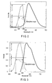
- FIG. 2 shows the spectrum characteristics of YAG:Ce.
- the broken line represents the absorption spectrum of YAG:Ce
- the solid line represents its emission spectrum.
- the absorption spectrum of YAG:Ce has its peak near 460 nm.
- the absorption range of the absorption spectrum is defined as a wavelength range where the absorption strength of the absorption spectrum of a given phosphor is half or more the peak value.
- the absorption range of the absorption spectrum of YAG:Ce is approximately 430 nm to 480 nm.
- the phosphor unit 62 absorbs 460-nm wavelength blue light emitted from the first semiconductor laser 22A to emit light having a wavelength of approximately 530 nm, but almost entirely transmits the 415-nm wavelength violet light emitted from the second semiconductor laser 22B.
- the first semiconductor laser 22A When the first semiconductor laser 22A is turned on, it emits 460-nm wavelength blue laser light. A beam of the laser light emitted from the first semiconductor laser 22A is converged by the lens 24 and then enters the optical fiber 30A. The laser light entering the optical fiber 30A is guided through the optical fiber 30A, travels through the optical fiber coupler 42, is guided through the optical fiber 50, and enters the phosphor unit 62. As is understood from FIG. 2 , the 460-nm wavelength blue laser light is light within the absorption range of YAG:Ce.
- part of the blue laser light entering the phosphor unit 62 is wavelength-converted by YAG:Ce in the phosphor unit 62 into broad-spectrum yellow light having a peak near a wavelength of 530 nm.
- the wavelength-converted yellow light is projected from the exit end of the phosphor unit 62.
- Part of the remaining blue laser light entering the phosphor unit 62 passes through the phosphor unit 62 without wavelength conversion and is projected from the exit end of the phosphor unit 62. Consequently, the yellow light wavelength-converted by the phosphor unit 62 and the blue light emitted from the semiconductor laser 22A are projected from the exit end of the phosphor unit 62.
- the yellow light and blue light are adjusted to form white light when mixed. As a result, white light is projected from the exit end of the phosphor unit 62. More specifically, when the first semiconductor laser 22A is turned on, white light as observation light for ordinary observation is projected from the exit end of the phosphor unit 62.
- the second semiconductor laser 22B When the second semiconductor laser 22B is turned on, it emits 415-nm wavelength violet laser light. A beam of the laser light emitted from the second semiconductor laser 22B is converged by the lens 24 and then enters the optical fiber 30B. The laser light entering the optical fiber 30B is guided through the optical fiber 30B, travels through the optical fiber coupler 42, is guided through the optical fiber 50, and enters the phosphor unit 62. As is understood from FIG. 2 , the 415-nm wavelength violet laser light is not included in the absorption range of YAG:Ce, and is accordingly hardly absorbed by YAG:Ce of the phosphor unit 62.
- the violet laser light entering the phosphor unit 62 passes through it almost entirely and is projected from its exit end. More specifically, when the second semiconductor laser 22B is turned on, 415-nm wavelength violet light as observation light for special observation is projected from the exit end of the phosphor unit 62.
- the light projected from the phosphor unit 62 when only the first semiconductor laser 22A is turned on and the light projected from the phosphor unit 62 when only the second semiconductor laser 22B is turned on have different colors.
- the white light as the observation light and the 415-nm wavelength violet light as the special light are switched without using any movable mechanism such as a slide guide unit, and the selected light is projected from the same exit end of the phosphor unit 62.
- a light source device that can perform switching between white light and violet light easily is fabricated. Since this light source device has a simple structure with no movable mechanism, it is suitable for downsizing.
- the 415-nm wavelength violet light is selected because it is largely absorbed by hemoglobin in the blood and thus facilitates observation of a blood vessel.
- the present invention is not limited to the light having this wavelength, but any light having a wavelength matching the observation object may be selected. More specifically, for YAG:Ce, light having a wavelength of 430 nm or less or light having a wavelength of 480 nm or more may be employed.
- the phosphor is not limited to YAG:Ce but any other appropriate phosphor such as a phosphor of Ce-activated Ca 3 SC 2 Si 3 O 12 may be employed.
- FIG. 3 shows the spectrum characteristics of Ce-activated Ca 3 Sc 2 Si 3 O 12 .
- the broken line represents the absorption spectrum, and its solid line represents the emission spectrum.
- the absorption range of Ce-activated Ca 3 Sc 2 Si 3 O 12 is approximately 460 nm to 530 nm.
- the wavelength of the excitation light of the first semiconductor laser 22A may be set to, e.g., approximately 500 nm, so that the excitation light is wavelength-converted more efficiently to obtain bright illumination light.
- a light source device will be described with reference to FIGS. 4 to 9 .
- a description on portions that are common with their equivalents in the first embodiment will not be repeated, and portions that are different from their equivalents will mainly be made.
- FIG. 4 shows a light source device according to the second embodiment.
- a light source device 10A according to the second embodiment has a third light source 20C in place of the first light source 20A, an optical fiber 30C in place of the optical fiber 30A, and a phosphor unit 62A in place of the phosphor unit 62.
- the third light source 20C has a third semiconductor laser 22C, a lens 24 to converge divergent light emitted from the third semiconductor laser 22C, and a connecting element 26 to optically connect the light converged by the lens 24 to the optical fiber 30C.
- the light source device 10A also has, in place of the driving circuit 82A, a driving circuit 82C to switch light on and light off of the third semiconductor laser 22C, that is, turns on and off the third semiconductor laser 22C independently. Except for this, the arrangement of the second embodiment is the same as that of the first embodiment.
- the third semiconductor laser 22C emits near-ultraviolet light having a wavelength of 375 nm.
- the phosphor unit 62A comprises a multiphosphor unit including different types of phosphors having different compositions.
- FIG. 5 shows the phosphor unit 62A shown in FIG. 4 .
- the phosphor unit 62A comprises the multiphosphor unit formed by stacking a region 66A including R phosphors 64A to emit red light, a region 66B including G phosphors 64B to emit green light, and a region 66C including B phosphors 64C to emit blue light sequentially from the incident end side to the exit light source.
- phosphors 64A, 64B, and 64C those that respectively emit red light, green light, and blue light upon being excited by 375-nm light as near-ultraviolet light are selected.
- such phosphors 64A, 64B, and 64C may be Eu-activated La 2 O 2 S (red), Eu, Mn-activated BaMgAl 10 O 17 (green), and Eu-activated BaMgAl 10 O 17 (blue), respectively.
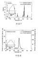
- FIG. 7 shows the emission spectrum of Eu-activated La 2 O 2 S (red)
- FIG. 8 shows the emission spectrum of Eu, Mn-activated BaMgAl 10 O 17 (green)
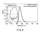
- FIG. 9 shows the emission spectrum of Eu-activated BaMgAl 10 O 17 (blue).
- the absorption ranges of these phosphors are 270 nm to 400 nm, 230 nm to 400 nm, and 270 nm to 410 nm, respectively.
- the absorption range of the multiphosphor unit including these phosphors can be regarded as the overlapping range of the absorption ranges of all the phosphors, which is 270 nm to 400 nm.
- the third semiconductor laser 22C When the third semiconductor laser 22C is turned on, it emits 375-nm wavelength near-ultraviolet laser light. A beam of near-ultraviolet laser light emitted from the third semiconductor laser 22C is converged by the lens 24 and enters the optical fiber 30C. The laser light entering the optical fiber 30C is guided through the optical fiber 30C, travels through an optical fiber coupler 42, is guided through an optical fiber 50, and enters the phosphor unit 62A. As shown in FIG.
- the region 66A including the R phosphors 64A to emit red light, the region 66B including the G phosphors 64B to emit green light, and the region 66C including the B phosphors 64C to emit blue light are arranged sequentially from the incident end side connected to the optical fiber 50.
- the 375-nm wavelength light emitted from the third semiconductor laser 22C is light within the absorption range of the multiphosphor unit constituting the phosphor unit 62A.
- part of the near-ultraviolet light entering the region 66A is wavelength-converted by the R phosphors 64A into red light, and the red light enters the region 66B.
- Part of the remaining near-ultraviolet light entering the region 66A passes through the region 66A and enters the region 66B.
- Part of the near-ultraviolet light entering the region 66B is wavelength-converted by the G phosphors 64B into green light, and the green light enters the region 66C.
- the G phosphors 64B do not absorb red light, the red light entering the region 66B passes through the region 66B. Therefore, red light, green light, and near-ultraviolet light enter the region 66C including the B phosphors 64C.
- the near-ultraviolet light entering the region 66C is wavelength-converted by the B phosphors 64C into blue light almost entirely.
- the B phosphors 64C do not absorb red light and green light, the red light and green light entering the region 66C pass through the region 66C. As a result, white light as a mixture of the red light, green light, and blue light is projected from the exit end of the phosphor unit 62A.
- the second semiconductor laser 22B When the second semiconductor laser 22B is turned on, it emits 415-nm wavelength violet laser light.
- a beam of light emitted from the second semiconductor laser 22B is converged by a lens 24, enters an optical fiber 30B, is guided through the optical fiber 30B, travels through the optical fiber coupler 42, is guided through the optical fiber 50, and enters the phosphor unit 62A, as described in the first embodiment.
- the 415-nm wavelength violet light is not light within the absorption range of the multi-phosphor unit.
- the violet light entering the phosphor unit 62A is hardly absorbed by the R phosphors 64A, G phosphors 64B, or B phosphors 64C, but passes through the phosphor unit 62A and is projected from the exit end of the phosphor unit 62A.
- the light source device 10A projects white light when the third semiconductor laser 22C is selectively turned on, and 415-nm wavelength violet light when the second semiconductor laser 22B is turned on.
- the white light projected from the light source device 10A has components of red light, green light, and blue light, it forms illumination light having higher color rendering properties when compared to the first embodiment.
- a light source device having the same advantages as and better color rendering properties than those of the first embodiment is fabricated.
- the phosphor unit 62A comprises a multiphosphor unit formed by stacking the region 66A including the R phosphors 64A, the region 66B including the G phosphors 64B, and the region 66C including the B phosphors 64C.
- the phosphor unit 62A may comprise another type of multiphosphor unit in which all of the phosphors 64A, 64B, and 64C are mixed. This simplifies the phosphor unit 62A.
- a light source device will be described with reference to FIG. 10 .
- a description on portions that are common with their equivalents in the first embodiment will not be repeated, and portions that are different from their equivalents will mainly be described.
- FIG. 10 shows the light source device according to the third embodiment.
- a light source device 10B according to this embodiment comprises a two-input, two-output optical fiber coupler 42A, which has two incident ends and two exit ends. Two optical fibers 50 and two phosphor units 62 are connected to the two exit ends of the optical fiber coupler 42A.
- the third embodiment is different from the first embodiment in these respects.
- the optical fiber coupler 42A has the two incident ends and two exit ends.
- the optical fiber coupler 42A distributes light entering one incident end to the two exit ends with substantially equal light intensity proportions, and light entering the other incident end to the two exit ends with substantially equal light intensity proportions.
- a wavelength converter 60 has the two phosphor units 62.
- the two phosphor units 62 are optically connected to the two exit ends of the optical fiber coupler 42A, respectively through the two optical fibers 50.
- the two phosphor units 62 have substantially equal wavelength conversion characteristics.
- the 460-nm wavelength blue light emitted from the first semiconductor laser 22A is guided through the optical fiber 30A and enters the optical fiber coupler 42A.
- the blue light entering the optical fiber coupler 42A is distributed by the optical fiber coupler 42A to the two optical fibers 50 with substantially equal intensities.
- the blue light distributed to the two optical fibers 50 are respectively guided through the two optical fibers 50 and enter the two phosphor units 62.
- the blue light entering each phosphor unit 62 forms white light in which blue light and wavelength-converted yellow light are mixed, and the white light is projected from the corresponding phosphor unit 62, as described in the first embodiment.
- the 415-nm wavelength violet light emitted from the second semiconductor laser 22B is guided through the optical fiber 30B and enters the optical fiber coupler 42A.
- the violet light entering the optical fiber coupler 42A is distributed by the optical fiber coupler 42A to the two optical fibers 50 with almost equal intensities.
- the violet light distributed to the two optical fibers 50 are respectively guided through the two optical fibers 50 and enter the two phosphor units 62.
- the violet light entering each phosphor unit 62 is directly projected from it, as described in the first embodiment.
- a light source device that has the advantages of the first embodiment and can illuminate the observation target from two directions is fabricated.
- illumination from only one direction may form a shadow, making the observation target difficult to observe.
- the exit ends of two phosphor units are arranged to illuminate the observation target from two directions, the observation target will not form a shadow easily.
- a light source device that is more suitable for observation is fabricated without making the apparatus bulky.
- each phosphor unit of the wavelength converter 60 comprises the phosphor unit 62 described in the first embodiment.
- each phosphor unit may comprise the multiphosphor unit 62A described in the second embodiment.
- the photocoupler 40 may be changed to an optical fiber coupler having three or more output ends, and the three or more output ends of the optical fiber coupler may be respectively connected to phosphor units and optical fibers corresponding in number to the output ends of the optical photocoupler.
- the light source device basically has an arrangement identical to that of the first embodiment, but is different from the first embodiment in that a wavelength converter 60 comprises a phosphor unit including two types of phosphors having different excitation wavelength characteristics.
- a phosphor unit 62 comprises a phosphor unit including the first phosphor that wavelength-converts blue laser light emitted from a first semiconductor laser 22A but hardly wavelength-converts violet laser light emitted from a second semiconductor laser 22B, and the second phosphor that does not wavelength-convert the blue laser light emitted from the first semiconductor laser 22A but wavelength-converts the violet laser light emitted from the second semiconductor laser 22B.
- the first phosphor comprises YAG:Ce
- the second phosphor comprises Eu-activated SrAl 2 O 4 (to be described as SrAlO:Eu hereinafter).
- FIG. 2 shows the spectrum characteristics of YAG:Ce
- FIG. 11 shows the spectrum characteristics of SrAlO:Eu.
- the absorption range of YAG:Ce as the first phosphor is 430 nm to 480 nm
- the absorption range of SrAlO as the second phosphor is 270 nm to 430 nm.
- the first semiconductor laser 22A emits 460-nm wavelength blue laser light.
- the laser light emitted from the first semiconductor laser 22A is guided through an optical fiber 30A, travels through an optical fiber coupler 42, is guided through an optical fiber 50, and enters the phosphor unit 62.
- the phosphor unit 62 includes YAG:Ce having the characteristics shown in FIG. 2 and SrAlO:Eu having the characteristics shown in Fig. 11 .
- the 460-nm wavelength blue light is light within the absorption range of YAG:Ce and outside the absorption range of SrAlO:Eu.
- the blue light entering the phosphor unit 62 is efficiently wavelength-converted by YAG:Ce into yellow light having a wavelength of approximately 530 nm, but is hardly wavelength-converted by SrAlO:Eu. Consequently, white light as a mixture of the blue light and the yellow light, which is wavelength-converted by YAG:Ce, is projected from the exit end of the phosphor unit 62.
- the second semiconductor laser 22B emits 415-nm wavelength violet laser light.
- the laser light emitted from the second semiconductor laser 22B is guided through an optical fiber 30B, travels through the optical fiber coupler 42, is guided through the optical fiber 50, and enters the phosphor unit 62.
- the 415-nm wavelength violet light is light within the absorption range of SrAlO:Eu and outside the absorption range of YAG:Ce.
- the violet light entering the phosphor unit 62 is hardly wavelength-converted by YAG:Ce, but is efficiently wavelength-converted by SrAlO:Eu into green light having a wavelength of approximately 540 nm. Consequently, as shown in FIG. 12 , light as a mixture of 415-nm wavelength violet light and 540-nm wavelength green light is projected from the exit end of the phosphor unit 62.
- the wavelengths of the mixed light generally coincide with the absorption wavelengths of hemoglobin, so that the mixed light is suitable for observation of the blood vessel with a high contrast.
- a light source device that has the advantages of the first embodiment and is suitable for observation of a blood vessel or the like with a high contrast is fabricated.
- this light source device merely the number of types of phosphors included in the phosphor unit 62 increases and no other major change is needed. Hence, the apparatus does not become bulky.
- the light source comprises a semiconductor laser in all the embodiments described above, the light source is not limited to this, but can comprise another semiconductor light source such as a light-emitting diode.
- a light-emitting diode When a light-emitting diode is used, a less expensive light source device is fabricated than a case in which a semiconductor laser is used.
- the light source device according to any embodiment descried above is particularly suitably mounted in an endoscope apparatus.
- FIG. 13 schematically shows a general endoscope apparatus.
- an endoscope apparatus 100 has a control unit 110, an inserting portion 120 extending from the control unit 110, and an endoscope end portion 130 located at the end of the inserting portion 120.
- the observation target is close to the endoscope end portion 130. If the exit position of ordinary observation light is shifted from that of special light, inconveniences such as color separation occur.
- the light source device according to any one of the embodiments described above, the exit position of ordinary observation light coincides with that of special light, so color separation does not occur.
- this light source device is particularly suitably mounted in an endoscope apparatus.
- FIG. 14 shows the arrangement of a general endoscope end portion 130.
- the endoscope end portion 130 has three end metal members 132A, 132B, and 132C, and a cover 144 that covers them.
- the two end metal members 132A and 132C are connected to each other through a heat-insulating material 134A, and the two end metal members 132B and 132C are connected to each other through a heat-insulating material 134B.
- the end metal member 132C is provided with a solid-state image sensor 136, an air/water supply nozzle 138, and a suction channel 140.
- the end metal members 132A and 132B are respectively provided with illumination light guide units 142.
- the endoscope apparatus generally has the two light guide units 142.
- two light source devices each having one light-emitting portion may be built into the endoscope apparatus, as shown in FIGS. 1 and 4 , or only one light source device having two light-emitting portions may be built into the endoscope apparatus, as shown in FIG. 10 .
- the wavelength converter 60 When mounting the light source device of any embodiment described above in the endoscope apparatus, the wavelength converter 60 may be arranged near the endoscope end portion 130, or light projected from the wavelength converter 60 may be guided to the endoscope end portion 130 through another optical fiber.
- the former arrangement is preferable for obtaining high-luminance illumination light.
- the latter arrangement is preferable for suppressing heat generation near the endoscope end portion because a phosphor unit that emits heat is arranged away from the endoscope end portion.
Landscapes
- Physics & Mathematics (AREA)
- Health & Medical Sciences (AREA)
- Life Sciences & Earth Sciences (AREA)
- Optics & Photonics (AREA)
- Surgery (AREA)
- Engineering & Computer Science (AREA)
- General Physics & Mathematics (AREA)
- Nuclear Medicine, Radiotherapy & Molecular Imaging (AREA)
- Animal Behavior & Ethology (AREA)
- Veterinary Medicine (AREA)
- Public Health (AREA)
- Biophysics (AREA)
- General Health & Medical Sciences (AREA)
- Pathology (AREA)
- Radiology & Medical Imaging (AREA)
- Molecular Biology (AREA)
- Biomedical Technology (AREA)
- Heart & Thoracic Surgery (AREA)
- Medical Informatics (AREA)
- General Engineering & Computer Science (AREA)
- Spectroscopy & Molecular Physics (AREA)
- Condensed Matter Physics & Semiconductors (AREA)
- Electromagnetism (AREA)
- Astronomy & Astrophysics (AREA)
- Microelectronics & Electronic Packaging (AREA)
- Endoscopes (AREA)
- Instruments For Viewing The Inside Of Hollow Bodies (AREA)
Abstract
Description
- The present invention relates to a light source device.
- Currently, an endoscope apparatus performs, in addition to ordinary observation using white light, a narrow band imaging, that is, an observation scheme in which the visibility of a lesion part or the like is improved using light having a specific wavelength. The endoscope apparatus having such a function is, more specifically, configured to switch between white light for ordinary observation and light having a specific wavelength for narrow band imaging, which is referred as special light hereinafter, projecting selected light from the end portion of an endoscope.
- Jpn. Pat. Appln. KOKAI Publication No.
2006-026128 - Since switching between the white light and special light is performed by sliding the unit, the light source device described above requires a mechanism for sliding the unit. This results in a bulky, complicated device.
- The present invention has been made in view of this situation, and as has its object to provide a compact light source device that can switch the projection light colors.
- A light source device according to the present invention includes a first semiconductor light source, a second semiconductor light source, and a wavelength converter. The first semiconductor light source emits light in a first wavelength range. The second semiconductor light source emits light in a second wavelength range different from the first wavelength range. The wavelength converter absorbs the light in the first wavelength range to emit light in a third wavelength range different from either of the first wavelength range and the second wavelength range, and transmits the light in the second wavelength range substantially entirely.
- According to the present invention, a compact light source device that can switch the projection light colors is provided.
- The invention can be more fully understood from the following detailed description when taken in conjunction with the accompanying drawings, in which:
-
FIG. 1 shows a light source device according to the first embodiment of the present invention; -
FIG. 2 shows the spectrum characteristics of YAG:Ce; -
FIG. 3 shows the spectrum characteristics of Ce-activated Ca3Sc2Si3O12; -
FIG. 4 shows a light source device according to the second embodiment of the present invention; -
FIG. 5 shows a multi-phosphor unit shown inFIG. 4 ; -
FIG. 6 shows another type of multi-phosphor unit, which can replace the multi-phosphor unit shown inFIG. 5 ; -
FIG. 7 shows the emission spectrum of Eu-activated La2O2S; -
FIG. 8 shows the emission spectrum of Eu, Mn-activated BaMgAl10O17; -
FIG. 9 shows the emission spectrum of Eu-activated BaMgAl10O17; -
FIG. 10 shows a light source device according to the third embodiment of the present invention; -
FIG. 11 shows the spectrum characteristics of SrAlO:Eu; -
FIG. 12 shows the spectrum of light projected from the phosphor unit of a light source device according to the fourth embodiment of the present invention; -
FIG. 13 schematically shows a general endoscope apparatus; and -
FIG. 14 shows the arrangement of an endoscope end portion shown inFIG. 13 . - The embodiments of the present invention will be described with reference to the accompanying drawing.
-
FIG. 1 shows a light source device according to the first embodiment of the present invention. As shown inFIG. 1 , alight source device 10 has afirst light source 20A, asecond light source 20B, an optical fiber 30A to guide light projected from thefirst light source 20A, anoptical fiber 30B to guide light projected from thesecond light source 20B, aphotocoupler 40 connected to theoptical fibers 30A and 30B, anoptical fiber 50 to guide light output from thephotocoupler 40, and awavelength converter 60 to emit illumination light corresponding to the light guided by theoptical fiber 50. - The
first light source 20A has afirst semiconductor laser 22A, alens 24 to converge divergent light emitted from thefirst semiconductor laser 22A, and a connectingelement 26 to optically connect the light converged by thelens 24 to the optical fiber 30A. Similarly, thesecond light source 20B has asecond semiconductor laser 22B, alens 24 to converge divergent light emitted from thesecond semiconductor laser 22B, and a connectingelement 26 to optically connect the light converged by thelens 24 to theoptical fiber 30B. - The
light source device 10 further has adriving circuit 82A to switch light on and light off of thefirst semiconductor laser 22A, that is, turns on and off thefirst semiconductor laser 22A independently, and adriving circuit 82B to switch light on and light off of thesecond semiconductor laser 22B, that is, turns on and off thesecond semiconductor laser 22B independently. - The
photocoupler 40 comprises a two-input, one-outputoptical fiber coupler 42, which has two incident ends and one exit end. One incident end of theoptical fiber coupler 42 is optically connected to thefirst light source 20A through the optical fiber 30A. The other incident end of theoptical fiber coupler 42 is optically connected to thesecond light source 20B through theoptical fiber 30B. The exit end of theoptical fiber coupler 42 is optically connected to thewavelength converter 60 through theoptical fiber 50. - The photocoupler referred to here is what serves to optically connect light from incident ends to at least one exit end, and its connection structure is not limited at all. For example, the photocoupler may be one fabricated by removing the claddings of two or more optical fibers respectively partially, and then heating and pressing the optical fibers in contact with each other, thus connecting the cores of the optical fibers. Alternatively, the photocoupler may be one fabricated by bringing the ends of parallel optical fibers into contact with the end of another optical fiber that opposes them, and heating the resultant structure, thus connecting the optical fibers to the opposing optical fiber. In these two examples, the connecting portion may be called part of the photocoupler, or the connecting portion itself may be called the photocoupler. In either case, the incident optical fibers to guide incident light to the connecting portion can be called incident optical fibers connected to the incident end of the photocoupler, and the exit optical fiber to guide light emerging from the connecting portion to the exit end can be called an exit optical fiber connected to the exit end of the photocoupler.
- The
first semiconductor laser 22A emits blue laser light having a wavelength of 460 nm, and thesecond semiconductor laser 22B emits violet laser light having a wavelength of 415 nm. Thewavelength converter 60 comprises aphosphor unit 62 including a phosphor of Ce (cerium)-activated YAG (yttrium-aluminum-garnet) (to be referred to as YAG:Ce hereinafter).FIG. 2 shows the spectrum characteristics of YAG:Ce. InFIG. 2 , the broken line represents the absorption spectrum of YAG:Ce, and the solid line represents its emission spectrum. As shown inFIG. 2 , the absorption spectrum of YAG:Ce has its peak near 460 nm. The absorption range of the absorption spectrum is defined as a wavelength range where the absorption strength of the absorption spectrum of a given phosphor is half or more the peak value. The absorption range of the absorption spectrum of YAG:Ce is approximately 430 nm to 480 nm. Thephosphor unit 62 absorbs 460-nm wavelength blue light emitted from thefirst semiconductor laser 22A to emit light having a wavelength of approximately 530 nm, but almost entirely transmits the 415-nm wavelength violet light emitted from thesecond semiconductor laser 22B. - The operation of the light source device according to this embodiment will be described.
- First, operation that takes place when the
first semiconductor laser 22A is turned on will be described. When thefirst semiconductor laser 22A is turned on, it emits 460-nm wavelength blue laser light. A beam of the laser light emitted from thefirst semiconductor laser 22A is converged by thelens 24 and then enters the optical fiber 30A. The laser light entering the optical fiber 30A is guided through the optical fiber 30A, travels through theoptical fiber coupler 42, is guided through theoptical fiber 50, and enters thephosphor unit 62. As is understood fromFIG. 2 , the 460-nm wavelength blue laser light is light within the absorption range of YAG:Ce. Thus, part of the blue laser light entering thephosphor unit 62 is wavelength-converted by YAG:Ce in thephosphor unit 62 into broad-spectrum yellow light having a peak near a wavelength of 530 nm. The wavelength-converted yellow light is projected from the exit end of thephosphor unit 62. Part of the remaining blue laser light entering thephosphor unit 62 passes through thephosphor unit 62 without wavelength conversion and is projected from the exit end of thephosphor unit 62. Consequently, the yellow light wavelength-converted by thephosphor unit 62 and the blue light emitted from thesemiconductor laser 22A are projected from the exit end of thephosphor unit 62. In this embodiment, the yellow light and blue light are adjusted to form white light when mixed. As a result, white light is projected from the exit end of thephosphor unit 62. More specifically, when thefirst semiconductor laser 22A is turned on, white light as observation light for ordinary observation is projected from the exit end of thephosphor unit 62. - Subsequently, operation that takes place when the
second semiconductor laser 22B is turned on will be described. When thesecond semiconductor laser 22B is turned on, it emits 415-nm wavelength violet laser light. A beam of the laser light emitted from thesecond semiconductor laser 22B is converged by thelens 24 and then enters theoptical fiber 30B. The laser light entering theoptical fiber 30B is guided through theoptical fiber 30B, travels through theoptical fiber coupler 42, is guided through theoptical fiber 50, and enters thephosphor unit 62. As is understood fromFIG. 2 , the 415-nm wavelength violet laser light is not included in the absorption range of YAG:Ce, and is accordingly hardly absorbed by YAG:Ce of thephosphor unit 62. Thus, the violet laser light entering thephosphor unit 62 passes through it almost entirely and is projected from its exit end. More specifically, when thesecond semiconductor laser 22B is turned on, 415-nm wavelength violet light as observation light for special observation is projected from the exit end of thephosphor unit 62. - In this manner, the light projected from the
phosphor unit 62 when only thefirst semiconductor laser 22A is turned on and the light projected from thephosphor unit 62 when only thesecond semiconductor laser 22B is turned on have different colors. - In the
light source device 10 of this embodiment, when one of the first andsecond semiconductor lasers phosphor unit 62. - By combining the two
semiconductor lasers photocoupler 40, andwavelength converter 60, a light source device that can perform switching between white light and violet light easily is fabricated. Since this light source device has a simple structure with no movable mechanism, it is suitable for downsizing. - In this embodiment, the 415-nm wavelength violet light is selected because it is largely absorbed by hemoglobin in the blood and thus facilitates observation of a blood vessel. However, the present invention is not limited to the light having this wavelength, but any light having a wavelength matching the observation object may be selected. More specifically, for YAG:Ce, light having a wavelength of 430 nm or less or light having a wavelength of 480 nm or more may be employed.
- The phosphor is not limited to YAG:Ce but any other appropriate phosphor such as a phosphor of Ce-activated Ca3SC2Si3O12 may be employed.
FIG. 3 shows the spectrum characteristics of Ce-activated Ca3Sc2Si3O12. InFIG. 3 , the broken line represents the absorption spectrum, and its solid line represents the emission spectrum. As shown inFIG. 3 , the absorption range of Ce-activated Ca3Sc2Si3O12 is approximately 460 nm to 530 nm. Hence, when using this phosphor, the wavelength of the excitation light of thefirst semiconductor laser 22A may be set to, e.g., approximately 500 nm, so that the excitation light is wavelength-converted more efficiently to obtain bright illumination light. - A light source device according to the second embodiment will be described with reference to
FIGS. 4 to 9 . In the second embodiment, a description on portions that are common with their equivalents in the first embodiment will not be repeated, and portions that are different from their equivalents will mainly be made. -
FIG. 4 shows a light source device according to the second embodiment. As shown inFIG. 4 , when compared to thelight source device 10 of the first embodiment, alight source device 10A according to the second embodiment has a thirdlight source 20C in place of the firstlight source 20A, anoptical fiber 30C in place of the optical fiber 30A, and aphosphor unit 62A in place of thephosphor unit 62. The thirdlight source 20C has athird semiconductor laser 22C, alens 24 to converge divergent light emitted from thethird semiconductor laser 22C, and a connectingelement 26 to optically connect the light converged by thelens 24 to theoptical fiber 30C. Thelight source device 10A also has, in place of the drivingcircuit 82A, a drivingcircuit 82C to switch light on and light off of thethird semiconductor laser 22C, that is, turns on and off thethird semiconductor laser 22C independently. Except for this, the arrangement of the second embodiment is the same as that of the first embodiment. - The
third semiconductor laser 22C emits near-ultraviolet light having a wavelength of 375 nm. Thephosphor unit 62A comprises a multiphosphor unit including different types of phosphors having different compositions.FIG. 5 shows thephosphor unit 62A shown inFIG. 4 . As shown inFIG. 5 , thephosphor unit 62A comprises the multiphosphor unit formed by stacking aregion 66A includingR phosphors 64A to emit red light, aregion 66B includingG phosphors 64B to emit green light, and aregion 66C includingB phosphors 64C to emit blue light sequentially from the incident end side to the exit light source. As thephosphors such phosphors FIG. 7 shows the emission spectrum of Eu-activated La2O2S (red),FIG. 8 shows the emission spectrum of Eu, Mn-activated BaMgAl10O17 (green), andFIG. 9 shows the emission spectrum of Eu-activated BaMgAl10O17 (blue). As shown inFIGS. 7 to 9 , the absorption ranges of these phosphors are 270 nm to 400 nm, 230 nm to 400 nm, and 270 nm to 410 nm, respectively. The absorption range of the multiphosphor unit including these phosphors can be regarded as the overlapping range of the absorption ranges of all the phosphors, which is 270 nm to 400 nm. - The operation of the light source device according to the second embodiment will be described.
- When the
third semiconductor laser 22C is turned on, it emits 375-nm wavelength near-ultraviolet laser light. A beam of near-ultraviolet laser light emitted from thethird semiconductor laser 22C is converged by thelens 24 and enters theoptical fiber 30C. The laser light entering theoptical fiber 30C is guided through theoptical fiber 30C, travels through anoptical fiber coupler 42, is guided through anoptical fiber 50, and enters thephosphor unit 62A. As shown inFIG. 5 , in thephosphor unit 62A, theregion 66A including theR phosphors 64A to emit red light, theregion 66B including theG phosphors 64B to emit green light, and theregion 66C including theB phosphors 64C to emit blue light are arranged sequentially from the incident end side connected to theoptical fiber 50. The 375-nm wavelength light emitted from thethird semiconductor laser 22C is light within the absorption range of the multiphosphor unit constituting thephosphor unit 62A. Thus, part of the near-ultraviolet light entering theregion 66A is wavelength-converted by theR phosphors 64A into red light, and the red light enters theregion 66B. Part of the remaining near-ultraviolet light entering theregion 66A passes through theregion 66A and enters theregion 66B. Part of the near-ultraviolet light entering theregion 66B is wavelength-converted by theG phosphors 64B into green light, and the green light enters theregion 66C. As theG phosphors 64B do not absorb red light, the red light entering theregion 66B passes through theregion 66B. Therefore, red light, green light, and near-ultraviolet light enter theregion 66C including theB phosphors 64C. The near-ultraviolet light entering theregion 66C is wavelength-converted by theB phosphors 64C into blue light almost entirely. As theB phosphors 64C do not absorb red light and green light, the red light and green light entering theregion 66C pass through theregion 66C. As a result, white light as a mixture of the red light, green light, and blue light is projected from the exit end of thephosphor unit 62A. - When the
second semiconductor laser 22B is turned on, it emits 415-nm wavelength violet laser light. A beam of light emitted from thesecond semiconductor laser 22B is converged by alens 24, enters anoptical fiber 30B, is guided through theoptical fiber 30B, travels through theoptical fiber coupler 42, is guided through theoptical fiber 50, and enters thephosphor unit 62A, as described in the first embodiment. The 415-nm wavelength violet light is not light within the absorption range of the multi-phosphor unit. Thus, the violet light entering thephosphor unit 62A is hardly absorbed by the R phosphors 64A, G phosphors 64B, orB phosphors 64C, but passes through thephosphor unit 62A and is projected from the exit end of thephosphor unit 62A. - As a result, the
light source device 10A projects white light when thethird semiconductor laser 22C is selectively turned on, and 415-nm wavelength violet light when thesecond semiconductor laser 22B is turned on. As the white light projected from thelight source device 10A has components of red light, green light, and blue light, it forms illumination light having higher color rendering properties when compared to the first embodiment. More specifically, according to the second embodiment, a light source device having the same advantages as and better color rendering properties than those of the first embodiment is fabricated. - In the second embodiment, as shown in
FIG. 5 , thephosphor unit 62A comprises a multiphosphor unit formed by stacking theregion 66A including the R phosphors 64A, theregion 66B including the G phosphors 64B, and theregion 66C including theB phosphors 64C. Alternatively, as shown inFIG. 6 , thephosphor unit 62A may comprise another type of multiphosphor unit in which all of thephosphors phosphor unit 62A. - A light source device according to the third embodiment will be described with reference to
FIG. 10 . In the third embodiment, a description on portions that are common with their equivalents in the first embodiment will not be repeated, and portions that are different from their equivalents will mainly be described. -
FIG. 10 shows the light source device according to the third embodiment. As shown inFIG. 10 , alight source device 10B according to this embodiment comprises a two-input, two-outputoptical fiber coupler 42A, which has two incident ends and two exit ends. Twooptical fibers 50 and twophosphor units 62 are connected to the two exit ends of theoptical fiber coupler 42A. The third embodiment is different from the first embodiment in these respects. - The
optical fiber coupler 42A has the two incident ends and two exit ends. Theoptical fiber coupler 42A distributes light entering one incident end to the two exit ends with substantially equal light intensity proportions, and light entering the other incident end to the two exit ends with substantially equal light intensity proportions. Awavelength converter 60 has the twophosphor units 62. The twophosphor units 62 are optically connected to the two exit ends of theoptical fiber coupler 42A, respectively through the twooptical fibers 50. The twophosphor units 62 have substantially equal wavelength conversion characteristics. - The 460-nm wavelength blue light emitted from the
first semiconductor laser 22A is guided through the optical fiber 30A and enters theoptical fiber coupler 42A. The blue light entering theoptical fiber coupler 42A is distributed by theoptical fiber coupler 42A to the twooptical fibers 50 with substantially equal intensities. The blue light distributed to the twooptical fibers 50 are respectively guided through the twooptical fibers 50 and enter the twophosphor units 62. The blue light entering eachphosphor unit 62 forms white light in which blue light and wavelength-converted yellow light are mixed, and the white light is projected from thecorresponding phosphor unit 62, as described in the first embodiment. - The 415-nm wavelength violet light emitted from the
second semiconductor laser 22B is guided through theoptical fiber 30B and enters theoptical fiber coupler 42A. The violet light entering theoptical fiber coupler 42A is distributed by theoptical fiber coupler 42A to the twooptical fibers 50 with almost equal intensities. The violet light distributed to the twooptical fibers 50 are respectively guided through the twooptical fibers 50 and enter the twophosphor units 62. The violet light entering eachphosphor unit 62 is directly projected from it, as described in the first embodiment. - According to this embodiment, a light source device that has the advantages of the first embodiment and can illuminate the observation target from two directions is fabricated. For example, as in an endoscope apparatus, when the observation target is very close to the light source, illumination from only one direction may form a shadow, making the observation target difficult to observe. When the exit ends of two phosphor units are arranged to illuminate the observation target from two directions, the observation target will not form a shadow easily. As a result, a light source device that is more suitable for observation is fabricated without making the apparatus bulky.
- According to this embodiment, each phosphor unit of the
wavelength converter 60 comprises thephosphor unit 62 described in the first embodiment. Alternatively, each phosphor unit may comprise themultiphosphor unit 62A described in the second embodiment. Also, thephotocoupler 40 may be changed to an optical fiber coupler having three or more output ends, and the three or more output ends of the optical fiber coupler may be respectively connected to phosphor units and optical fibers corresponding in number to the output ends of the optical photocoupler. - A light source device according to the fourth embodiment will be described. The light source device according to this embodiment basically has an arrangement identical to that of the first embodiment, but is different from the first embodiment in that a
wavelength converter 60 comprises a phosphor unit including two types of phosphors having different excitation wavelength characteristics. - A
phosphor unit 62 according to this embodiment comprises a phosphor unit including the first phosphor that wavelength-converts blue laser light emitted from afirst semiconductor laser 22A but hardly wavelength-converts violet laser light emitted from asecond semiconductor laser 22B, and the second phosphor that does not wavelength-convert the blue laser light emitted from thefirst semiconductor laser 22A but wavelength-converts the violet laser light emitted from thesecond semiconductor laser 22B. - In this embodiment, for example, the first phosphor comprises YAG:Ce, and the second phosphor comprises Eu-activated SrAl2O4 (to be described as SrAlO:Eu hereinafter).
FIG. 2 shows the spectrum characteristics of YAG:Ce, andFIG. 11 shows the spectrum characteristics of SrAlO:Eu. The absorption range of YAG:Ce as the first phosphor is 430 nm to 480 nm, and the absorption range of SrAlO as the second phosphor is 270 nm to 430 nm. - The operation of the fourth embodiment will be described.
- Operation that takes place when the
first semiconductor laser 22A is turned on will be described first. As described in the first embodiment, thefirst semiconductor laser 22A emits 460-nm wavelength blue laser light. The laser light emitted from thefirst semiconductor laser 22A is guided through an optical fiber 30A, travels through anoptical fiber coupler 42, is guided through anoptical fiber 50, and enters thephosphor unit 62. Thephosphor unit 62 includes YAG:Ce having the characteristics shown inFIG. 2 and SrAlO:Eu having the characteristics shown inFig. 11 . The 460-nm wavelength blue light is light within the absorption range of YAG:Ce and outside the absorption range of SrAlO:Eu. Hence, the blue light entering thephosphor unit 62 is efficiently wavelength-converted by YAG:Ce into yellow light having a wavelength of approximately 530 nm, but is hardly wavelength-converted by SrAlO:Eu. Consequently, white light as a mixture of the blue light and the yellow light, which is wavelength-converted by YAG:Ce, is projected from the exit end of thephosphor unit 62. - Operation that takes place when the
second semiconductor laser 22B is turned on will be described. As described in the first embodiment, thesecond semiconductor laser 22B emits 415-nm wavelength violet laser light. The laser light emitted from thesecond semiconductor laser 22B is guided through anoptical fiber 30B, travels through theoptical fiber coupler 42, is guided through theoptical fiber 50, and enters thephosphor unit 62. The 415-nm wavelength violet light is light within the absorption range of SrAlO:Eu and outside the absorption range of YAG:Ce. Hence, the violet light entering thephosphor unit 62 is hardly wavelength-converted by YAG:Ce, but is efficiently wavelength-converted by SrAlO:Eu into green light having a wavelength of approximately 540 nm. Consequently, as shown inFIG. 12 , light as a mixture of 415-nm wavelength violet light and 540-nm wavelength green light is projected from the exit end of thephosphor unit 62. The wavelengths of the mixed light generally coincide with the absorption wavelengths of hemoglobin, so that the mixed light is suitable for observation of the blood vessel with a high contrast. - According to this embodiment, a light source device that has the advantages of the first embodiment and is suitable for observation of a blood vessel or the like with a high contrast is fabricated. In this light source device, merely the number of types of phosphors included in the
phosphor unit 62 increases and no other major change is needed. Hence, the apparatus does not become bulky. - Although the light source comprises a semiconductor laser in all the embodiments described above, the light source is not limited to this, but can comprise another semiconductor light source such as a light-emitting diode. When a light-emitting diode is used, a less expensive light source device is fabricated than a case in which a semiconductor laser is used.
- The light source device according to any embodiment descried above is particularly suitably mounted in an endoscope apparatus.
-
FIG. 13 schematically shows a general endoscope apparatus. As shown inFIG. 13 , anendoscope apparatus 100 has acontrol unit 110, an insertingportion 120 extending from thecontrol unit 110, and anendoscope end portion 130 located at the end of the insertingportion 120. In observation using such anendoscope apparatus 100, the observation target is close to theendoscope end portion 130. If the exit position of ordinary observation light is shifted from that of special light, inconveniences such as color separation occur. In contrast to this, with the light source device according to any one of the embodiments described above, the exit position of ordinary observation light coincides with that of special light, so color separation does not occur. Thus, this light source device is particularly suitably mounted in an endoscope apparatus. -
FIG. 14 shows the arrangement of a generalendoscope end portion 130. As shown inFIG. 14 , theendoscope end portion 130 has threeend metal members cover 144 that covers them. The twoend metal members material 134A, and the twoend metal members material 134B. Theend metal member 132C is provided with a solid-state image sensor 136, an air/water supply nozzle 138, and asuction channel 140. Theend metal members light guide units 142. - In this manner, the endoscope apparatus generally has the two
light guide units 142. When mounting the light source device of any embodiment described above in the endoscope apparatus, two light source devices each having one light-emitting portion may be built into the endoscope apparatus, as shown inFIGS. 1 and4 , or only one light source device having two light-emitting portions may be built into the endoscope apparatus, as shown inFIG. 10 . - When mounting the light source device of any embodiment described above in the endoscope apparatus, the
wavelength converter 60 may be arranged near theendoscope end portion 130, or light projected from thewavelength converter 60 may be guided to theendoscope end portion 130 through another optical fiber. The former arrangement is preferable for obtaining high-luminance illumination light. The latter arrangement is preferable for suppressing heat generation near the endoscope end portion because a phosphor unit that emits heat is arranged away from the endoscope end portion.
Claims (14)
- A light source device characterized by comprising:a first semiconductor light source to emit light in a first wavelength range;a second semiconductor light source to emit light in a second wavelength range different from the first wavelength range; anda wavelength converter to absorb the light in the first wavelength range to emit light in a third wavelength range different from either of the first wavelength range and the second wavelength range, and to transmit the light in the second wavelength range substantially entirely.
- The device according to claim 1, characterized in that the light in the third wavelength range has a wavelength longer than that of the light in the first wavelength range, the device further comprises a first light source driving circuit to switch light on and light off of the first semiconductor light source independently, and a second light source driving circuit to switch light on and light off of the second semiconductor light source independently, and first illumination light projected from the wavelength converter when only the first semiconductor light source is turned on and second illumination light projected from the wavelength converter when only the second semiconductor light source is turned on have different colors.
- The device according to claim 2, characterized by further comprising a photocoupler including a first incident end and a second incident end that are optically connected to the first semiconductor light source and the second semiconductor light source, respectively, and at least one exit end that is optically connected to the wavelength converter.
- The device according to claim 2, characterized in that the first illumination light comprises white light, and the second illumination light comprises light with a color substantially the same as that of the light in the second wavelength range.
- The device according to claim 1, characterized in that the wavelength converter includes a first phosphor, and the first wavelength range comprises an absorption range of an absorption spectrum of the first phosphor.
- The device according to claim 5, characterized in that the first phosphor comprises cerium-activated yttrium-aluminum-garnet, the first wavelength range comprises a range of 430 nm to 480 nm, and the second wavelength range comprises a range of not more than 430 nm and/or not less than 480 nm.
- The device according to claim 1, characterized in that the wavelength converter includes different types of phosphors having different composition, the different types of phosphors being selected so as to absorb the light in the first wavelength range to emit light having wavelengths that are longer than that of the light in the first wavelength range and different from each other, and the first wavelength range comprises an overlapping range of absorption ranges of absorption spectra of the different types of phosphor materials.
- The device according to claim 7, characterized in that the first wavelength range is not more than 410 nm, the different types of phosphors emit red light, green light, and blue light, respectively, upon being excited by the light in the first wavelength range, and the wavelength converter projects white light as a mixture of the red light, the green light, and the blue light.
- The device according to claim 3, characterized by further comprising a first incident optical fiber to optically connect the first semiconductor light source to the first incident end of the photocoupler, a second incident optical fiber to optically connect the second semiconductor light source to the second incident end of the photocoupler, and at least one exit optical fiber to optically connect the wavelength converter to the at least one exit end of the photocoupler.
- The device according to claim 9, characterized in that the at least one exit end of the photocoupler includes a first exit end and a second exit end, the photocoupler distributes light entering the first incident end to the first exit end and the second exit end with substantially equal light intensity proportions, and light entering the second incident end to the first exit end and the second exit end with substantially equal light intensity proportions, the at least one exit optical fiber includes a first exit optical fiber and a second exit optical fiber, and the wavelength converter includes a first phosphor unit optically connected to the first exit end through the first exit optical fiber and a second phosphor unit optically connected to the second exit end through the second exit optical fiber, the first phosphor unit and the second phosphor unit having substantially equal wavelength conversion characteristics.
- The device according to claim 5, characterized in that the wavelength converter further includes a second phosphor, the second phosphor being selected so as to absorb light in the second wavelength range to emit light having a wavelength longer than that of the light in the second wavelength range and different from that of the light in the first wavelength range.
- The device according to claim 11, characterized in that the light source device projects white light when the first semiconductor light source is selectively turned on, and light as a mixture of the light emitted from the second semiconductor light source and the light emitted from the second phosphor when the second semiconductor light source is selectively turned on.
- An endoscope apparatus comprising a light source device according to claim 10.
- An endoscope apparatus comprising a light source device according to claim 12.
Applications Claiming Priority (1)
| Application Number | Priority Date | Filing Date | Title |
|---|---|---|---|
| JP2007335321A JP2009153712A (en) | 2007-12-26 | 2007-12-26 | Light source device and endoscope apparatus comprising the same |
Publications (2)
| Publication Number | Publication Date |
|---|---|
| EP2074934A2 true EP2074934A2 (en) | 2009-07-01 |
| EP2074934A3 EP2074934A3 (en) | 2009-08-05 |
Family
ID=40403984
Family Applications (1)
| Application Number | Title | Priority Date | Filing Date |
|---|---|---|---|
| EP08171890A Withdrawn EP2074934A3 (en) | 2007-12-26 | 2008-12-17 | Light source device and endoscope apparatus comprising the same |
Country Status (3)
| Country | Link |
|---|---|
| US (7) | US8698387B2 (en) |
| EP (1) | EP2074934A3 (en) |
| JP (1) | JP2009153712A (en) |
Cited By (8)
| Publication number | Priority date | Publication date | Assignee | Title |
|---|---|---|---|---|
| WO2010006275A1 (en) * | 2008-07-10 | 2010-01-14 | Corporation For Laser Optics Research | Blue laser pumped green light source for displays |
| EP2229870A1 (en) * | 2009-03-18 | 2010-09-22 | FUJIFILM Corporation | Endoscope system, endoscope video processor and method of driving endoscope system |
| WO2014028758A1 (en) * | 2012-08-15 | 2014-02-20 | Arthrex, Inc. | Endoscopic camera illumination system and method |
| EP2767756A4 (en) * | 2011-10-11 | 2015-07-08 | Olympus Corp | Light-source device |
| EP2927560A1 (en) * | 2014-04-04 | 2015-10-07 | Maquet SAS | Surgical lighting apparatus with offset laser source |
| US9332895B2 (en) | 2009-10-21 | 2016-05-10 | Olympus Corporation | Light irradiating apparatus |
| EP2952132A4 (en) * | 2013-01-29 | 2016-10-05 | Olympus Corp | Light source device, subject observation device and light source control method |
| CN108119779A (en) * | 2016-11-30 | 2018-06-05 | 日亚化学工业株式会社 | Light-emitting device and its manufacturing method |
Families Citing this family (67)
| Publication number | Priority date | Publication date | Assignee | Title |
|---|---|---|---|---|
| US8435276B2 (en) * | 2006-02-27 | 2013-05-07 | Thomas Perez | Method and apparatus for the combined application of light therapy, optic diagnosis, and fluid to tissue |
| JP2009153712A (en) | 2007-12-26 | 2009-07-16 | Olympus Corp | Light source device and endoscope apparatus comprising the same |
| JP5117878B2 (en) * | 2008-02-13 | 2013-01-16 | 富士フイルム株式会社 | Endoscope light source device |
| DE602009001103D1 (en) * | 2008-06-04 | 2011-06-01 | Fujifilm Corp | Lighting device for use in endoscopes |
| JP5216429B2 (en) * | 2008-06-13 | 2013-06-19 | 富士フイルム株式会社 | Light source device and endoscope device |
| JP4558104B2 (en) * | 2008-10-27 | 2010-10-06 | オリンパスメディカルシステムズ株式会社 | Intra-subject introduction device and medical system |
| JP5767775B2 (en) * | 2009-07-06 | 2015-08-19 | 富士フイルム株式会社 | Endoscope device |
| CN105832278B (en) * | 2009-07-23 | 2018-03-06 | 奥林巴斯株式会社 | Penetrance adjusting apparatus, observation device and observing system |
| JP5401205B2 (en) * | 2009-08-10 | 2014-01-29 | 富士フイルム株式会社 | Endoscope device |
| JP5317893B2 (en) * | 2009-08-31 | 2013-10-16 | 富士フイルム株式会社 | Endoscope system |
| JP5460506B2 (en) * | 2009-09-24 | 2014-04-02 | 富士フイルム株式会社 | Endoscope apparatus operating method and endoscope apparatus |
| JP5460507B2 (en) * | 2009-09-24 | 2014-04-02 | 富士フイルム株式会社 | Endoscope apparatus operating method and endoscope apparatus |
| JP5544219B2 (en) * | 2009-09-24 | 2014-07-09 | 富士フイルム株式会社 | Endoscope system |
| JP5325725B2 (en) | 2009-09-24 | 2013-10-23 | 富士フイルム株式会社 | Endoscope device |
| JP2011147757A (en) * | 2009-09-29 | 2011-08-04 | Fujifilm Corp | Medical apparatus and endoscope apparatus |
| JP5371858B2 (en) * | 2009-09-29 | 2013-12-18 | 富士フイルム株式会社 | Electronic endoscope device |
| JP5645385B2 (en) * | 2009-09-29 | 2014-12-24 | 富士フイルム株式会社 | Endoscopic light projecting unit and endoscopic device equipped with the same |
| JP5371702B2 (en) * | 2009-11-06 | 2013-12-18 | 富士フイルム株式会社 | Electronic endoscope system, processor device for electronic endoscope, and method for operating electronic endoscope system |
| JP5606120B2 (en) * | 2010-03-29 | 2014-10-15 | 富士フイルム株式会社 | Endoscope device |
| JP2012016545A (en) * | 2010-07-09 | 2012-01-26 | Fujifilm Corp | Endoscope apparatus |
| JP5258869B2 (en) * | 2010-12-13 | 2013-08-07 | 富士フイルム株式会社 | Endoscope device |
| JP5554253B2 (en) * | 2011-01-27 | 2014-07-23 | 富士フイルム株式会社 | Electronic endoscope system |
| CN103443535A (en) * | 2011-03-30 | 2013-12-11 | 奥林巴斯株式会社 | Light source unit, optical conversion unit, light source device, and light source system |
| JP5485215B2 (en) * | 2011-04-01 | 2014-05-07 | 富士フイルム株式会社 | Endoscope device |
| JP5331904B2 (en) * | 2011-04-15 | 2013-10-30 | 富士フイルム株式会社 | Endoscope system and method for operating endoscope system |
| JP5851140B2 (en) * | 2011-07-28 | 2016-02-03 | オリンパス株式会社 | Light source device |
| JP5450527B2 (en) | 2011-08-10 | 2014-03-26 | 富士フイルム株式会社 | Endoscope device |
| JP5303015B2 (en) * | 2011-08-29 | 2013-10-02 | 富士フイルム株式会社 | Endoscopic diagnosis device |
| JP2014171511A (en) * | 2013-03-06 | 2014-09-22 | Olympus Corp | Subject observation system and method thereof |
| JP5698781B2 (en) * | 2013-03-18 | 2015-04-08 | オリンパス株式会社 | LIGHT SOURCE DEVICE AND ENDOSCOPE DEVICE EQUIPPED WITH THE SAME |
| JP5698782B2 (en) * | 2013-03-18 | 2015-04-08 | オリンパス株式会社 | LIGHT SOURCE DEVICE AND ENDOSCOPE DEVICE EQUIPPED WITH THE SAME |
| JP5718398B2 (en) * | 2013-03-18 | 2015-05-13 | オリンパス株式会社 | Endoscope device |
| JP2014121630A (en) * | 2014-02-10 | 2014-07-03 | Fujifilm Corp | Endoscope device |
| JP6412709B2 (en) * | 2014-04-02 | 2018-10-24 | オリンパス株式会社 | Observation image acquisition system |
| DE102014210492A1 (en) | 2014-06-03 | 2015-12-03 | Osram Gmbh | Conversion device for converting radiation of an excitation radiation source into conversion radiation and method for producing such a conversion device |
| EP3151721B1 (en) * | 2014-06-04 | 2019-09-25 | Gyrus ACMI, Inc. (d.b.a.Olympus Surgical Technologies America) | Illumination balancing and solid state narrow band imaging utilizing fiber bundle design and assembly techniques in endoscopes |
| JP6201904B2 (en) * | 2014-06-10 | 2017-09-27 | 豊田合成株式会社 | Light emitting device |
| CN106574175B (en) | 2014-09-11 | 2018-08-07 | 飞利浦照明控股有限公司 | White with reinforcement shows the PC-LED modules with transfer efficiency |
| JP5879422B2 (en) * | 2014-11-10 | 2016-03-08 | 富士フイルム株式会社 | Endoscope device |
| JP2015091351A (en) * | 2014-12-24 | 2015-05-14 | 富士フイルム株式会社 | Endoscope device |
| JP6359998B2 (en) * | 2015-04-22 | 2018-07-18 | パナソニック株式会社 | Endoscope |
| JP6680868B2 (en) | 2015-08-17 | 2020-04-15 | インフィニット アースロスコピー インコーポレーテッド, リミテッド | light source |
| WO2017087448A1 (en) | 2015-11-16 | 2017-05-26 | Infinite Arthroscopy Inc, Limited | Wireless medical imaging system |
| GB2546329A (en) * | 2016-01-15 | 2017-07-19 | Barco Nv | System and method for endoscope calibration |
| JP2016105824A (en) * | 2016-02-08 | 2016-06-16 | 富士フイルム株式会社 | Endoscope apparatus |
| WO2017141417A1 (en) * | 2016-02-19 | 2017-08-24 | Hoya株式会社 | Endoscope light source device |
| WO2017175391A1 (en) * | 2016-04-08 | 2017-10-12 | オリンパス株式会社 | Illuminating device and endoscope including same |
| JP6209642B2 (en) * | 2016-04-13 | 2017-10-04 | 富士フイルム株式会社 | Endoscope device |
| JP6155367B2 (en) * | 2016-06-17 | 2017-06-28 | 富士フイルム株式会社 | Endoscope device |
| JP6264706B1 (en) | 2016-07-04 | 2018-01-24 | パナソニックIpマネジメント株式会社 | Projector device |
| WO2018008283A1 (en) | 2016-07-04 | 2018-01-11 | パナソニックIpマネジメント株式会社 | Fiber light source, endoscope, and endoscope system |
| JP6340749B2 (en) | 2016-07-04 | 2018-06-13 | パナソニックIpマネジメント株式会社 | Light emitting device using phosphor |
| KR20190028628A (en) | 2016-07-04 | 2019-03-19 | 파나소닉 아이피 매니지먼트 가부시키가이샤 | Phosphor and light emitting device |
| CN109068968B (en) * | 2016-09-16 | 2021-02-05 | 奥林巴斯株式会社 | Light source device for endoscope |
| ES2955917T3 (en) | 2017-02-15 | 2023-12-11 | Lazurite Holdings Llc | Wireless medical imaging system comprising head unit and light cable comprising integrated light source |
| JP2017087078A (en) * | 2017-02-28 | 2017-05-25 | 富士フイルム株式会社 | Endoscope apparatus |
| JP6550420B2 (en) * | 2017-06-02 | 2019-07-24 | 富士フイルム株式会社 | Endoscope device |
| JP2017200601A (en) * | 2017-07-04 | 2017-11-09 | 富士フイルム株式会社 | Endoscope apparatus |
| JP6379260B2 (en) * | 2017-07-04 | 2018-08-22 | 富士フイルム株式会社 | Endoscope device |
| JP6505792B2 (en) * | 2017-08-29 | 2019-04-24 | 富士フイルム株式会社 | LIGHT SOURCE DEVICE FOR ENDOSCOPE AND ENDOSCOPE SYSTEM |
| JP6450492B1 (en) * | 2018-07-19 | 2019-01-09 | パナソニック株式会社 | Endoscopic illumination device and endoscope system |
| US12458217B2 (en) | 2019-02-04 | 2025-11-04 | Panasonic Intellectual Property Management Co., Ltd. | Light emitting device and medical device using same |
| WO2020217669A1 (en) * | 2019-04-24 | 2020-10-29 | パナソニックIpマネジメント株式会社 | Light emitting device; and medical system, electronic apparatus, and inspection method using same |
| WO2020243101A1 (en) * | 2019-05-24 | 2020-12-03 | Fraen Corporation | Cri-booster white laser fiber source |
| USD938584S1 (en) | 2020-03-30 | 2021-12-14 | Lazurite Holdings Llc | Hand piece |
| USD972176S1 (en) | 2020-08-06 | 2022-12-06 | Lazurite Holdings Llc | Light source |
| CN116709964A (en) * | 2021-01-27 | 2023-09-05 | 豪雅株式会社 | Phosphor illumination system for endoscopic imaging |
Citations (1)
| Publication number | Priority date | Publication date | Assignee | Title |
|---|---|---|---|---|
| JP2006026128A (en) | 2004-07-16 | 2006-02-02 | Pentax Corp | Endoscope light source device |
Family Cites Families (51)
| Publication number | Priority date | Publication date | Assignee | Title |
|---|---|---|---|---|
| JPH07155291A (en) | 1993-12-03 | 1995-06-20 | Olympus Optical Co Ltd | Fluorescence observation apparatus |
| TW383508B (en) | 1996-07-29 | 2000-03-01 | Nichia Kagaku Kogyo Kk | Light emitting device and display |
| JP3868050B2 (en) | 1997-02-06 | 2007-01-17 | オリンパス株式会社 | Endoscope |
| CA2306710A1 (en) | 1997-10-28 | 1999-05-06 | Rudi Beichel | An advanced technology pollution free, highly efficient industrial power generation system |
| JP3586157B2 (en) | 1999-12-20 | 2004-11-10 | オリンパス株式会社 | Subject observation device |
| CA2297476A1 (en) | 2000-01-21 | 2001-07-21 | Neks Recherche & Developpement Inc. | System for detection of dental tartar, e.g. subgingival tartar |
| US6577073B2 (en) * | 2000-05-31 | 2003-06-10 | Matsushita Electric Industrial Co., Ltd. | Led lamp |
| JP3607857B2 (en) | 2000-07-27 | 2005-01-05 | オリンパス株式会社 | Endoscope device |
| US7892169B2 (en) | 2000-07-21 | 2011-02-22 | Olympus Corporation | Endoscope apparatus |
| DE10109850A1 (en) | 2001-03-01 | 2002-09-05 | Wavelight Laser Technologie Ag | Device for generating white light |
| JP4390096B2 (en) | 2001-07-06 | 2009-12-24 | 富士フイルム株式会社 | Endoscope device |
| US6921920B2 (en) | 2001-08-31 | 2005-07-26 | Smith & Nephew, Inc. | Solid-state light source |
| JP3699040B2 (en) | 2001-11-22 | 2005-09-28 | オリンパス株式会社 | Electronic endoscope |
| US8229548B2 (en) | 2002-03-12 | 2012-07-24 | Beth Israel Deaconess Medical Center | Medical imaging systems |
| CN1493250A (en) | 2002-10-31 | 2004-05-05 | ƽ | Device using endoscope to diagnose precancer affection |
| JP4274843B2 (en) * | 2003-04-21 | 2009-06-10 | シャープ株式会社 | LED device and mobile phone device, digital camera and LCD display device using the same |
| KR100691143B1 (en) * | 2003-04-30 | 2007-03-09 | 삼성전기주식회사 | Light Emitting Diode with Multilayer Fluorescent Layer |
| US20050006659A1 (en) | 2003-07-09 | 2005-01-13 | Ng Kee Yean | Light emitting diode utilizing a discrete wavelength-converting layer for color conversion |
| JP2005039126A (en) | 2003-07-17 | 2005-02-10 | Sumitomo Electric Ind Ltd | Broadband light source |
| ATE445356T1 (en) | 2003-11-19 | 2009-10-15 | Wolf Gmbh Richard | DEVICE FOR IMAGING TISSUE DIAGNOSES |
| JP4554944B2 (en) | 2004-01-15 | 2010-09-29 | Hoya株式会社 | Endoscope device |
| TWI303751B (en) | 2004-03-16 | 2008-12-01 | Imec Inter Uni Micro Electr | Method of manufacturing a semiconductor device |
| JP4317478B2 (en) | 2004-03-31 | 2009-08-19 | 三菱化学株式会社 | Phosphor-type light emitting device and endoscope device using the same as an illumination source |
| JP4481751B2 (en) | 2004-07-09 | 2010-06-16 | Hoya株式会社 | The tip of the autofluorescence endoscope |
| JP4925618B2 (en) * | 2004-07-28 | 2012-05-09 | 京セラ株式会社 | Light source device and endoscope provided with the light source device |
| US20080262316A1 (en) * | 2004-07-28 | 2008-10-23 | Kyocera Corporation | Light Source Apparatus and Endoscope Provided with Light Source Apparatus |
| US7311858B2 (en) * | 2004-08-04 | 2007-12-25 | Intematix Corporation | Silicate-based yellow-green phosphors |
| JP5081370B2 (en) * | 2004-08-31 | 2012-11-28 | 日亜化学工業株式会社 | Light emitting device |
| US7758224B2 (en) | 2004-10-01 | 2010-07-20 | Nichia Corporation | Light emitting device |
| JP4729918B2 (en) | 2004-12-17 | 2011-07-20 | 日亜化学工業株式会社 | Light emitting device |
| US7433115B2 (en) | 2004-12-15 | 2008-10-07 | Nichia Corporation | Light emitting device |
| JP2006173324A (en) | 2004-12-15 | 2006-06-29 | Nichia Chem Ind Ltd | Light emitting device |
| JP4732783B2 (en) * | 2005-04-19 | 2011-07-27 | 富士フイルム株式会社 | Endoscope lighting system |
| JP2006314686A (en) * | 2005-05-16 | 2006-11-24 | Olympus Medical Systems Corp | Endoscope |
| JP4794916B2 (en) | 2005-06-16 | 2011-10-19 | オリンパスメディカルシステムズ株式会社 | Endoscope and endoscope system |
| US7621653B2 (en) * | 2005-11-22 | 2009-11-24 | Xenopus Electronix, Llc | Multi-function illumination device |
| KR100771811B1 (en) * | 2005-12-27 | 2007-10-30 | 삼성전기주식회사 | White light emitting device |
| JP4793684B2 (en) | 2006-03-23 | 2011-10-12 | 日亜化学工業株式会社 | Light emitting device |
| JP4740036B2 (en) | 2006-05-26 | 2011-08-03 | 積水化学工業株式会社 | Method for measuring hemoglobins |
| US7618176B2 (en) | 2006-06-22 | 2009-11-17 | Avago Technologies General Ip (Singapore) Pte. Ltd. | Solid state light source adapted for remote illumination |
| US20080192458A1 (en) * | 2007-02-12 | 2008-08-14 | Intematix Corporation | Light emitting diode lighting system |
| JP4017015B2 (en) | 2007-02-13 | 2007-12-05 | 日亜化学工業株式会社 | Light emitting device |
| JP2009039438A (en) * | 2007-08-10 | 2009-02-26 | Olympus Corp | Fiber optic lighting equipment |
| JP5214193B2 (en) | 2007-08-10 | 2013-06-19 | オリンパス株式会社 | Fiber light source |
| JP2009153712A (en) | 2007-12-26 | 2009-07-16 | Olympus Corp | Light source device and endoscope apparatus comprising the same |
| JP5401205B2 (en) | 2009-08-10 | 2014-01-29 | 富士フイルム株式会社 | Endoscope device |
| JP5698782B2 (en) | 2013-03-18 | 2015-04-08 | オリンパス株式会社 | LIGHT SOURCE DEVICE AND ENDOSCOPE DEVICE EQUIPPED WITH THE SAME |
| JP5698780B2 (en) | 2013-03-18 | 2015-04-08 | オリンパス株式会社 | LIGHT SOURCE DEVICE AND ENDOSCOPE DEVICE EQUIPPED WITH THE SAME |
| JP5718398B2 (en) | 2013-03-18 | 2015-05-13 | オリンパス株式会社 | Endoscope device |
| JP5698779B2 (en) | 2013-03-18 | 2015-04-08 | オリンパス株式会社 | Endoscope apparatus having light source device |
| JP5698781B2 (en) | 2013-03-18 | 2015-04-08 | オリンパス株式会社 | LIGHT SOURCE DEVICE AND ENDOSCOPE DEVICE EQUIPPED WITH THE SAME |
-
2007
- 2007-12-26 JP JP2007335321A patent/JP2009153712A/en active Pending
-
2008
- 2008-12-16 US US12/335,833 patent/US8698387B2/en active Active
- 2008-12-17 EP EP08171890A patent/EP2074934A3/en not_active Withdrawn
-
2013
- 2013-06-04 US US13/909,554 patent/US8810126B2/en active Active
-
2014
- 2014-06-02 US US14/293,587 patent/US9217545B2/en active Active
- 2014-06-02 US US14/293,551 patent/US9303830B2/en active Active
-
2016
- 2016-02-23 US US15/051,104 patent/US9587791B2/en active Active
- 2016-12-28 US US15/393,024 patent/US10156324B2/en active Active
-
2018
- 2018-11-08 US US16/184,204 patent/US10801677B2/en active Active
Patent Citations (1)
| Publication number | Priority date | Publication date | Assignee | Title |
|---|---|---|---|---|
| JP2006026128A (en) | 2004-07-16 | 2006-02-02 | Pentax Corp | Endoscope light source device |
Cited By (17)
| Publication number | Priority date | Publication date | Assignee | Title |
|---|---|---|---|---|
| WO2010006275A1 (en) * | 2008-07-10 | 2010-01-14 | Corporation For Laser Optics Research | Blue laser pumped green light source for displays |
| EP2229870A1 (en) * | 2009-03-18 | 2010-09-22 | FUJIFILM Corporation | Endoscope system, endoscope video processor and method of driving endoscope system |
| EP3075301A1 (en) * | 2009-03-18 | 2016-10-05 | FUJIFILM Corporation | Endoscope system, endoscope video processor and method of driving endoscope system |
| US8734333B2 (en) | 2009-03-18 | 2014-05-27 | Fujifilm Corporation | Endoscope system, endoscope video processor and method of driving endoscope system |
| US9332895B2 (en) | 2009-10-21 | 2016-05-10 | Olympus Corporation | Light irradiating apparatus |
| EP2767756A4 (en) * | 2011-10-11 | 2015-07-08 | Olympus Corp | Light-source device |
| US9435513B2 (en) | 2011-10-11 | 2016-09-06 | Olympus Corporation | Light source device having optical members for changing one or more characteristics of excitation light from an excitation light source |
| WO2014028758A1 (en) * | 2012-08-15 | 2014-02-20 | Arthrex, Inc. | Endoscopic camera illumination system and method |
| EP2952132A4 (en) * | 2013-01-29 | 2016-10-05 | Olympus Corp | Light source device, subject observation device and light source control method |
| US9814375B2 (en) | 2013-01-29 | 2017-11-14 | Olympus Corporation | Light source device and subject observation apparatus as well as light source control method |
| FR3019625A1 (en) * | 2014-04-04 | 2015-10-09 | Maquet Sas | OPERATIVE LIGHTING APPARATUS WITH LASER SOURCE DEPORTEE |
| EP2927560B1 (en) | 2014-04-04 | 2016-05-04 | Maquet SAS | Surgical lighting apparatus with offset laser source |
| EP2927560A1 (en) * | 2014-04-04 | 2015-10-07 | Maquet SAS | Surgical lighting apparatus with offset laser source |
| CN108119779A (en) * | 2016-11-30 | 2018-06-05 | 日亚化学工业株式会社 | Light-emitting device and its manufacturing method |
| EP3331108A1 (en) * | 2016-11-30 | 2018-06-06 | Nichia Corporation | Light emitting device and method of producing the light emitting device |
| US10648911B2 (en) | 2016-11-30 | 2020-05-12 | Nichia Corporation | Light emitting device |
| US11018471B2 (en) | 2016-11-30 | 2021-05-25 | Nichia Corporation | Method of producing light emitting device |
Also Published As
| Publication number | Publication date |
|---|---|
| US8810126B2 (en) | 2014-08-19 |
| US20140268642A1 (en) | 2014-09-18 |
| US8698387B2 (en) | 2014-04-15 |
| US20170108183A1 (en) | 2017-04-20 |
| US20090167149A1 (en) | 2009-07-02 |
| US10801677B2 (en) | 2020-10-13 |
| US9587791B2 (en) | 2017-03-07 |
| US9217545B2 (en) | 2015-12-22 |
| US20140268643A1 (en) | 2014-09-18 |
| US9303830B2 (en) | 2016-04-05 |
| EP2074934A3 (en) | 2009-08-05 |
| US20190072241A1 (en) | 2019-03-07 |
| US20130267781A1 (en) | 2013-10-10 |
| JP2009153712A (en) | 2009-07-16 |
| US10156324B2 (en) | 2018-12-18 |
| US20160169461A1 (en) | 2016-06-16 |
Similar Documents
| Publication | Publication Date | Title |
|---|---|---|
| US10801677B2 (en) | Light source device and endoscope apparatus comprising the same | |
| EP3222201B1 (en) | Endoscopic device | |
| US7780326B2 (en) | Optical fiber lighting apparatus | |
| US7672041B2 (en) | Optical fiber lighting apparatus | |
| US8790253B2 (en) | Light source device, imaging apparatus and endoscope apparatus | |
| JP2013111176A (en) | Light source device for endoscope | |
| CN103403438A (en) | Lighting apparatus with phosphor element | |
| JP6438062B2 (en) | Endoscope system | |
| JP2009277734A (en) | Semiconductor light source device | |
| JP6215981B2 (en) | LIGHT SOURCE DEVICE AND ENDOSCOPE DEVICE EQUIPPED WITH THE SAME | |
| JP5698781B2 (en) | LIGHT SOURCE DEVICE AND ENDOSCOPE DEVICE EQUIPPED WITH THE SAME | |
| JP5698779B2 (en) | Endoscope apparatus having light source device | |
| JP5698780B2 (en) | LIGHT SOURCE DEVICE AND ENDOSCOPE DEVICE EQUIPPED WITH THE SAME | |
| JP5718398B2 (en) | Endoscope device | |
| JP5890493B2 (en) | LIGHT SOURCE DEVICE AND ENDOSCOPE DEVICE EQUIPPED WITH THE SAME | |
| JP5698782B2 (en) | LIGHT SOURCE DEVICE AND ENDOSCOPE DEVICE EQUIPPED WITH THE SAME | |
| JP6515161B2 (en) | Light source device and endoscope apparatus provided with the same | |
| JP2015134230A (en) | Endoscope light source device |
Legal Events
| Date | Code | Title | Description |
|---|---|---|---|
| PUAI | Public reference made under article 153(3) epc to a published international application that has entered the european phase |
Free format text: ORIGINAL CODE: 0009012 |
|
| AK | Designated contracting states |
Kind code of ref document: A2 Designated state(s): AT BE BG CH CY CZ DE DK EE ES FI FR GB GR HR HU IE IS IT LI LT LU LV MC MT NL NO PL PT RO SE SI SK TR |
|
| AX | Request for extension of the european patent |
Extension state: AL BA MK RS |
|
| PUAL | Search report despatched |
Free format text: ORIGINAL CODE: 0009013 |
|
| AK | Designated contracting states |
Kind code of ref document: A3 Designated state(s): AT BE BG CH CY CZ DE DK EE ES FI FR GB GR HR HU IE IS IT LI LT LU LV MC MT NL NO PL PT RO SE SI SK TR |
|
| AX | Request for extension of the european patent |
Extension state: AL BA MK RS |
|
| AKX | Designation fees paid |
Designated state(s): DE NL |
|
| STAA | Information on the status of an ep patent application or granted ep patent |
Free format text: STATUS: THE APPLICATION IS DEEMED TO BE WITHDRAWN |
|
| 18D | Application deemed to be withdrawn |
Effective date: 20100206 |