EP2073769B1 - Improved tear-duct drain - Google Patents
Improved tear-duct drain Download PDFInfo
- Publication number
- EP2073769B1 EP2073769B1 EP07804206A EP07804206A EP2073769B1 EP 2073769 B1 EP2073769 B1 EP 2073769B1 EP 07804206 A EP07804206 A EP 07804206A EP 07804206 A EP07804206 A EP 07804206A EP 2073769 B1 EP2073769 B1 EP 2073769B1
- Authority
- EP
- European Patent Office
- Prior art keywords
- flange
- tube
- tear
- drain
- duct drain
- Prior art date
- Legal status (The legal status is an assumption and is not a legal conclusion. Google has not performed a legal analysis and makes no representation as to the accuracy of the status listed.)
- Active
Links
Images

Classifications
-
- A—HUMAN NECESSITIES
- A61—MEDICAL OR VETERINARY SCIENCE; HYGIENE
- A61F—FILTERS IMPLANTABLE INTO BLOOD VESSELS; PROSTHESES; DEVICES PROVIDING PATENCY TO, OR PREVENTING COLLAPSING OF, TUBULAR STRUCTURES OF THE BODY, e.g. STENTS; ORTHOPAEDIC, NURSING OR CONTRACEPTIVE DEVICES; FOMENTATION; TREATMENT OR PROTECTION OF EYES OR EARS; BANDAGES, DRESSINGS OR ABSORBENT PADS; FIRST-AID KITS
- A61F2/00—Filters implantable into blood vessels; Prostheses, i.e. artificial substitutes or replacements for parts of the body; Appliances for connecting them with the body; Devices providing patency to, or preventing collapsing of, tubular structures of the body, e.g. stents
- A61F2/02—Prostheses implantable into the body
- A61F2/14—Eye parts, e.g. lenses or corneal implants; Artificial eyes
-
- A—HUMAN NECESSITIES
- A61—MEDICAL OR VETERINARY SCIENCE; HYGIENE
- A61F—FILTERS IMPLANTABLE INTO BLOOD VESSELS; PROSTHESES; DEVICES PROVIDING PATENCY TO, OR PREVENTING COLLAPSING OF, TUBULAR STRUCTURES OF THE BODY, e.g. STENTS; ORTHOPAEDIC, NURSING OR CONTRACEPTIVE DEVICES; FOMENTATION; TREATMENT OR PROTECTION OF EYES OR EARS; BANDAGES, DRESSINGS OR ABSORBENT PADS; FIRST-AID KITS
- A61F9/00—Methods or devices for treatment of the eyes; Devices for putting in contact-lenses; Devices to correct squinting; Apparatus to guide the blind; Protective devices for the eyes, carried on the body or in the hand
- A61F9/007—Methods or devices for eye surgery
- A61F9/00772—Apparatus for restoration of tear ducts
Definitions
- the present invention relates to a medical device that has its main application in corrective tear-duct surgery.
- the improvements provided by the device greatly help to overcome the numerous disadvantages of previous approaches in this field.
- tear fluid that is "lacrimal” fluid
- lachrymal glands each being located in a lateral and superior relation to the respective eye.
- Upper lacrimal ducts feed the fluid from each gland to a respective conjunctival sac, in which the relevant eyeball is partially encased.
- the lacrimal fluid subsequently washes the sclera and other conjunctival components of the eye, as well as its cornea.
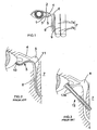
- any excess fluid has drained from the inner-canthus (1), it passes through a network of passages commencing with the puncta, which are seen as small papillae (2, 3) adjacent to the inner-canthus (1). From here, the lacrimal fluid is subsequently collected in the lacrimal sac (6), which is connected to the puncta via a number of canaliculi (4, 5). The lacrimal fluid is thereafter drained through the nasolacrimal duct (8) into the interior meatus (7b) of the nose.
- the resultant permanent closure can require a corrective surgical procedure known as a dacryocystorhinostomy (DCR).
- DCR dacryocystorhinostomy
- the sole blockage occurs in, for example, the nasolacrimal duct, the latter can be removed, and the remaining lacrimal sac cavity can then be joined directly with the mucosa of the nasal fossa. This is typically achieved by removing tissue, including the intervening segment of nasal bone and periosteum, so that the drainage of tear liquid into the nose can be more or less restored.
- the nasal bone heals around the lower end portion of the inserted replacement tube, the latter is gradually rejected from the bone and flesh of the patient. And secondly, the patient's flesh also tends to heal over the external end of the replacement tube at the inner-canthus (1), which therefore requires appropriate surgical reopening from time to time.
- the replacement tube utilised in tear-duct surgery has been a small tube constructed of PyrexTM glass, stiff plastic or some other relatively rigid material.
- PyrexTM-type glass that has been preferred, since this can neither be destroyed, nor corroded or otherwise affected by a patient's bodily fluids.
- double-flanged Jones-type tubes have also been previously made available. These have two opposing flanges at either end of a hollow shank, with the aim of attempting to prevent their rejection.
- these tubes tend not to be particularly effective either since, in practice, they have at least the following extra disadvantages:
- FR-A-2, 813, 522 discloses the use of a tubular lacrimal drain (11, 12) having one or more parts, one of which is an internal fixing unit. This allows anchoring of the drain (11,12), typically by providing a screw-threaded attachment means (10, 12a).
- CN-A-1, 650, 824 also provides an artificial tear duct, in this case being in the form of a spiral spring-like structure, typically used as a temporary stent to allow scar tissue to become stable before the spring is softened and thereafter pulled out as an unravelled metal wire.
- US-B-5, 062, 831 discloses the use of a solid tubing (16), having no lumen, for temporarily removing excess lacrimal fluid by capillary action.
- a conventional DCR is performed, by removing adjacent bone so that the remaining sac communicates with the internal nasal meatus (7).
- a catheter (13), with enlarged portions (15) at either end of an elongate shank portion (14), is used simply as a temporary stent to prevent scarring over of the newly opened hole between the sac and the nose.
- JP-A-2004-230, 012 discloses a tear duct stent (17) that has enlarged portions (or collars) (18; 19a, 19b) at either end of a tube (20).
- this stent is similar in shape to the above-described double-flanged Jones tube, but because this stent is formed of a soft material, the length of its tube can be adjusted as required by cutting it with scissors. Further, having been placed in situ, one or more of its collars may subsequently be cut away to allow the remainder of the stent to be pulled and so removed.
- GB2273243 A discloses a self retaining conjunctivo-rhinostomy tube comprising a tubular main body, outer retaining elements and inner retaining elements.
- the inner elements can be connected by straps to an introducer, or the tubular main body may be placed inside a sleeve introducer.
- WO2006133066 A2 discloses a lacrimal bypass drainage device comprising a cannula or tube having a flange on the ocular end and a threaded outer surface to provide for greater axial friction.
- the flange is keyed to allow engagement by a screwdriver type tool having a correspondingly keyed trocar mounted to a manipulable handle.
- a removable biocompatible washer is provided to discourage tissue overgrowth immediately after emplacement.
- One or more radial drainage holes can be formed near the distal end of the tube to overcome axial blockages.
- An alternate embodiment provides for a tube placed from the nasal side having nasal side radial protrusions and a removable eye side flange in the form of a keyed nut.
- the present invention aims to provide an improved device for correcting tear-duct obstructions and, in particular, for the correction of canalicular obstructions.
- the latter have previously tended to be even less successfully treated than blockages of other tear-duct system parts.
- the present invention provides a tear-duct drain as defined in claim 1.
- the device of the present invention has the advantages that it can be more accurately placed in situ and with greater ease than previous devices, as well as being able to be left more stably in situ afterwards. This befits the relatively more permanent correction that it can provide, if such permanency is required.
- Potentially permanent devices of this type also need to be easily removeable, at least temporarily, so that they can be cleansed along with the patient's consequently vacated tissue passageway. This helps to avoid, for example, microbial contamination, so that tissue damage resulting from inflammation is less likely to occur. If left unchecked, however, such damage would tend to increase the likelihood of rejection of the device from the patient.
- the elongated tube of each of these improved devices may be made of any suitably inert material that promotes a high level of biocompatibility with patient tissue, as well as the preferred ease of cleaning the device as a whole upon its temporary withdrawal.
- the tube of the present device has a first enlarged external portion at one end that is designed to act as an anchor at the corner of the patient's eye, it also has a collapsible second flange that is preferably positioned towards the opposite end of the tube. Because of its resilience and, typically, relatively large diameter, this second flange tends to prevent the device from slipping. This is because it helps to secure the tube in its in situ position, and so stabilise it against any forces (for example during sneezing of the nose or blinking of the eye) that it might experience thereafter. This is effected by the opening-up of the flexible flange inside the patient's nose and its subsequent positioning against the nasal mucosa around the internal opening of the tissue passageway.
- the flexible material of which the collapsible second flange is constructed has a relatively much smaller dimension of thinness compared to that of the diameter of the elongate tube.
- this second flange is consequently encouraged by the surrounding tissue of the passageway to flex.
- it can lie flush against the body of the tube, and to the appropriate side of the site of its bonding to the tube, depending upon the relative direction of movement of the tube.
- the tube may be indented on either side of the site of bonding to provide recesses (in the tube's surface) that can accommodate the second flange when flexed.
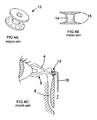
- the tear-duct drain (21) shown in Figure 6A has a first flange (28) at the external (that is, inner-canthal) opening (23) of its tube (24).
- a second flange (25) is also provided and is positioned close to - but not at - the internal (that is, nasal) opening (26) of the leading edge (27) of the tube (24).
- the tube (24) and first flange (28) are composed of a rigid material, for example a glass or a plastics material.
- a rigid material for example a glass or a plastics material.
- Glass is generally a preferred material, since it has excellent capillary characteristics and is very biocompatible.
- the relative dimensions, and relative resilience, of the second flange (25) are predetermined to allow the tube (24), when in situ, to be stable to any potentially destabilising forces that might otherwise cause either its movement inwards into the nose or outwards towards the eye. Patients are therefore provided with a significant safety benefit to their eyes. Complete loss of the device (21) is also reduced.
- the relative resilience of the second flange (25) can be defined in terms of the degree of the relative shear forces involved. That is, for example, the maximum shear force that the flange (25) can withstand before it collapses; and, the respective minimum that it can overcome before it bounces back into shape.
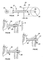
- the flexibility of the second flange (25) also ensures that it can collapse in both directions. That is, both: (i) towards the external end (28) of the tube (24) [a "first flush position”]; and, (ii) towards the leading edge (27) of the tube (24) [a "second flush position”].
- the position adopted depends upon the direction in which the tube is being urged by the surgeon.
- the second flange (25) can thus adopt the first flush position during the tube's insertion (that is, in direction I, as shown in Figure 6B ).
- the resilience of the second flange (25) enables it to spring open.
- This springing open can if necessary be facilitated by the surgeon, for example by applying a degree of manual pressure against the elasticity of the tissue area surrounding the nasal (inner) orifice of the lumen of the passageway, so as to aid release of folded flange into nasal meatus (7).
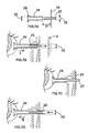
- such minimisation can optionally be achieved by adapting the tube's shape to include indentations on either side of the bonding site of the second flange, which can therefore adopt the flush positions by collapsing into and thus being held in the recesses (for example, 31) so created.
- the collapsible flange is typically bonded to the inert material of the tube (24) by a suitable adhesive.
- a suitable adhesive for example, any glue that can bond potential collapsible flange (25) material, such as silicone, to the material of the tube (24), for example glass, can be used.
- the chosen glue should also preferably be able to withstand high temperatures for autoclaving, as well as being generally tissue biocompatible.
- the shape of the flange (25) at its site of bonding to the tube may be splayed to allow greater strength.
- the splaying (34, 35, 36) may advantageously allow the flange (25) to have a greater surface area that can be adhered to the tube (24).
- the bonded second flange (25) can be made of any appropriately flexible material that retains its memory after deformation, such as, for example a silicone or a rubber, or indeed alternatively any suitable plastics material.
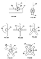
- the exact shape of the second flange (25) can be chosen to suit the needs of each specific patient and so it need not necessarily be circular (as shown in Figure 6A ) in cross-section.
- FIG. 9A-E further non-limiting examples of the many different types that can be appropriately utilised are shown in Figures 9A-E .
- the second flange (25) comprises a plurality of arms radiating from the central lumen (26)
- the outer circumferential profile of the second flange (25) is preferably as uniformly smooth as possible, for example any arms should preferably have rounded extremities.
- the second flange (25) is pre-bonded at a predetermined set distance (22) from the internal end (27) of the glass tube (24), and so the clinician need not actually bond the second flange (25) to the tube (24) at any stage.
- the glass tubes are also typically manufactured to predetermined lengths, so that, the length required to match each patient's anatomy can be chosen by the surgeon before the corrective procedure is commenced.
- the improvements provided by the device (21) of the present invention allow it to be inserted, if necessary, as a relatively permanent system, often as an independent bypass of a patient's natural tear-duct system.
- the chosen parameters of the device (21) and particularly those of its second flange (25), greatly enhance its ability to efficiently provide this permanent type of treatment, by avoiding counterproductive complications (such as inflammation of the nearby tissues, and so forth) that, as mentioned above, might otherwise arise.
- the present device (21) is particularly suited to correction of canalicular obstructions.
- the device (21) can easily be placed into the correct in situ position (as shown in Figure 6C ). By making use of the slight elasticity of the intervening tissue, this can be achieved by inserting it inwardly into the passage (see Figure 6B ) until the leading edge (27) of the tube is sufficiently inside the nasal meatus (7).
- This allows the internal second flange (25) to have already flexibly opened out due to its inherent resilience.
- the device (21) can then be withdrawn slightly until the opened second flange (25) abuts the nasal mucosa surrounding the internal orifice of the bypass passage.
- the positioning of the internal second flange (25), and thus the in situ placement of the device (21) as a whole, can therefore be accurately controlled by the clinician.
- the bonding of the second flange (25) to the tube (24) at a predetermined distance from the internal end (27) of the tube ensures that a section (22) of the tube is proud of the second flange (25). Being proud, its obstruction (for example by the formation of scar tissue from the nasal mucosa) is much less likely when it is in situ, so helping to promote a more continuous drainage of the excess lacrimal fluid.
- Devices according to the present invention may, of course, differ in their absolute dimensions from case to case, with these being specifically chosen so as to maximise the above-described advantages for each individual patient.
- the outer diameter of the first, rigid flange (28) might be chosen to be between about 3 to 4mm, whilst that of the tube (24) would then suitably be about 2-2.5mm.
- the diameter of the second flange (25) would typically be of the order of 7.5mm or less, and preferably about 5mm.
- Its thickness (29) would consequently be of the order of 1mm or less, and the tube's proud section (22) would also generally have a chosen length of about 1mm.
- any recesses (31) as mentioned above - for example see Figure 7 - can also be varied to accommodate the associated dimensions chosen for the second flange (25).
- portion of the tube (24) adjacent to the edges of the flange (25) can be raised slightly to provide support.
- the advantages of the improved device according to the present invention include the following.
- the device does not depend upon gravity, by having the relatively large weight flanges that are used in some known devices.
- the device also does not rely upon its tube having to be cut to size or glued during its insertion, or its flanges being cut off to allow its withdrawal.
Landscapes
- Health & Medical Sciences (AREA)
- Ophthalmology & Optometry (AREA)
- Animal Behavior & Ethology (AREA)
- Veterinary Medicine (AREA)
- Public Health (AREA)
- Engineering & Computer Science (AREA)
- Biomedical Technology (AREA)
- Heart & Thoracic Surgery (AREA)
- Vascular Medicine (AREA)
- Life Sciences & Earth Sciences (AREA)
- General Health & Medical Sciences (AREA)
- Plastic & Reconstructive Surgery (AREA)
- Surgery (AREA)
- Nuclear Medicine, Radiotherapy & Molecular Imaging (AREA)
- Cardiology (AREA)
- Oral & Maxillofacial Surgery (AREA)
- Transplantation (AREA)
- External Artificial Organs (AREA)
- Rigid Pipes And Flexible Pipes (AREA)
- Materials For Medical Uses (AREA)
- Prostheses (AREA)
- Infusion, Injection, And Reservoir Apparatuses (AREA)
- Surgical Instruments (AREA)
Applications Claiming Priority (2)
| Application Number | Priority Date | Filing Date | Title |
|---|---|---|---|
| GB0619305A GB2442205B (en) | 2006-09-29 | 2006-09-29 | Improved tear-duct drain |
| PCT/GB2007/003408 WO2008037951A1 (en) | 2006-09-29 | 2007-09-11 | Improved tear-duct drain |
Publications (2)
| Publication Number | Publication Date |
|---|---|
| EP2073769A1 EP2073769A1 (en) | 2009-07-01 |
| EP2073769B1 true EP2073769B1 (en) | 2010-11-10 |
Family
ID=37434974
Family Applications (1)
| Application Number | Title | Priority Date | Filing Date |
|---|---|---|---|
| EP07804206A Active EP2073769B1 (en) | 2006-09-29 | 2007-09-11 | Improved tear-duct drain |
Country Status (7)
| Country | Link |
|---|---|
| US (1) | US7758534B2 (enExample) |
| EP (1) | EP2073769B1 (enExample) |
| JP (1) | JP5197608B2 (enExample) |
| AT (1) | ATE487448T1 (enExample) |
| DE (1) | DE602007010497D1 (enExample) |
| GB (1) | GB2442205B (enExample) |
| WO (1) | WO2008037951A1 (enExample) |
Families Citing this family (14)
| Publication number | Priority date | Publication date | Assignee | Title |
|---|---|---|---|---|
| USD590935S1 (en) * | 2005-06-06 | 2009-04-21 | Becker Bruce B | Lacrimal drainage tube |
| GB2456796B (en) | 2008-01-24 | 2012-08-08 | Ljt Projects Ltd | Ophalmic sizing tubes |
| US20100049207A1 (en) * | 2008-08-22 | 2010-02-25 | Turmes Jr Nicolas A | Jones tube inserter |
| US9022967B2 (en) | 2010-10-08 | 2015-05-05 | Sinopsys Surgical, Inc. | Implant device, tool, and methods relating to treatment of paranasal sinuses |
| US9572964B2 (en) | 2012-04-11 | 2017-02-21 | Sinapsys Surgical, Inc. | Implantation tools, tool assemblies, kits and methods |
| BR112015017356B1 (pt) | 2013-01-25 | 2022-02-08 | Sinopsys Surgical, Inc | Dispositivo de implante de acesso de seio paranasal e kit para uso para tratar um seio paranasal |
| US10130507B2 (en) | 2013-08-03 | 2018-11-20 | Michael C. Whitehurst | Dry eye treatment device |
| WO2015069433A1 (en) | 2013-10-16 | 2015-05-14 | Sinopsys Surgical, Inc. | Apparatuses, tools and kits relating to fluid manipulation treatments of paranasal sinuses |
| JP2017522122A (ja) | 2014-07-24 | 2017-08-10 | シノプシス サージカル インコーポレイテッドSinopsys Surgical,Inc. | 副鼻腔アクセスインプラントデバイスおよび関連する製品ならびに方法 |
| WO2017180487A1 (en) | 2016-04-11 | 2017-10-19 | The Regents Of The University Of Michigan | Lacrimal stent with opening |
| CN107184295A (zh) * | 2017-07-19 | 2017-09-22 | 上海市同济医院 | 可调节泪道支架 |
| FI3675780T3 (fi) | 2017-09-20 | 2025-03-13 | Sinopsys Surgical Inc | Paranasaaliseen sinukseen nestepääsyn mahdollistavia implantointityökaluja ja -kokoonpanoja |
| JP6655158B1 (ja) * | 2018-12-04 | 2020-02-26 | 合同会社山鹿Cl | ステント |
| WO2020197955A1 (en) * | 2019-03-22 | 2020-10-01 | Dsm Ip Assets B.V. | Nasal dressings and stents |
Family Cites Families (15)
| Publication number | Priority date | Publication date | Assignee | Title |
|---|---|---|---|---|
| US3871380A (en) * | 1973-12-03 | 1975-03-18 | Richards Mfg Co | Myringotomy drain tube |
| US4695275A (en) * | 1983-12-16 | 1987-09-22 | Donald Bruce | Middle ear ventilation tube |
| GB2273243A (en) * | 1992-12-12 | 1994-06-15 | Vishwas Vasant Kayarkar | Self retaining conjunctivo-rhinostomy tube |
| US6406453B1 (en) * | 1995-04-26 | 2002-06-18 | Medtronic Xomed, Inc. | Composite ventilation tube |
| US6149684A (en) * | 1995-06-07 | 2000-11-21 | Herrick; Robert S. | Punctum plug having a thin elongated lip and a distal starting tip and method of using |
| US5723005A (en) * | 1995-06-07 | 1998-03-03 | Herrick Family Limited Partnership | Punctum plug having a collapsible flared section and method |
| US5993407A (en) * | 1996-10-25 | 1999-11-30 | Moazed; Kambiz Thomas | Transnasal lacrimal insert |
| CA2251223A1 (fr) * | 1997-02-04 | 1998-08-06 | Alain Fouere | Tampon meatique vissable pour canal lacrymal |
| US5830171A (en) * | 1997-08-12 | 1998-11-03 | Odyssey Medical, Inc. | Punctal occluder |
| US6629533B1 (en) * | 2000-06-30 | 2003-10-07 | Eagle Vision, Inc. | Punctum plug with at least one anchoring arm |
| FR2813522B1 (fr) * | 2000-09-06 | 2003-08-08 | Alain Fouere | Dispositif de drain lacrymal maintenu en place grace a un filetage externe |
| FR2841770B1 (fr) * | 2002-07-05 | 2004-10-01 | Ioltechnologie Production | Clou meatique d'obturation d'un meat lacrymal |
| JP2004230012A (ja) * | 2003-01-31 | 2004-08-19 | M L C:Kk | 涙道再建手術における涙丘移動術と涙道内挿管器具 |
| US20040204704A1 (en) * | 2003-04-10 | 2004-10-14 | Ceramoptec Industries, Inc. | Device and method for dacryocystorhinostomy |
| US20060276738A1 (en) | 2005-06-06 | 2006-12-07 | Becker Bruce B | Lacrimal drainage bypass device and method |
-
2006
- 2006-09-29 GB GB0619305A patent/GB2442205B/en active Active
-
2007
- 2007-04-02 US US11/695,300 patent/US7758534B2/en active Active
- 2007-09-11 EP EP07804206A patent/EP2073769B1/en active Active
- 2007-09-11 WO PCT/GB2007/003408 patent/WO2008037951A1/en not_active Ceased
- 2007-09-11 AT AT07804206T patent/ATE487448T1/de not_active IP Right Cessation
- 2007-09-11 DE DE602007010497T patent/DE602007010497D1/de active Active
- 2007-09-11 JP JP2009529750A patent/JP5197608B2/ja not_active Expired - Fee Related
Also Published As
| Publication number | Publication date |
|---|---|
| ATE487448T1 (de) | 2010-11-15 |
| GB0619305D0 (en) | 2006-11-08 |
| GB2442205B (en) | 2008-11-05 |
| US7758534B2 (en) | 2010-07-20 |
| WO2008037951A1 (en) | 2008-04-03 |
| US20080082037A1 (en) | 2008-04-03 |
| EP2073769A1 (en) | 2009-07-01 |
| JP5197608B2 (ja) | 2013-05-15 |
| JP2010504784A (ja) | 2010-02-18 |
| GB2442205A (en) | 2008-04-02 |
| DE602007010497D1 (de) | 2010-12-23 |
Similar Documents
| Publication | Publication Date | Title |
|---|---|---|
| EP2073769B1 (en) | Improved tear-duct drain | |
| AU2002250452B2 (en) | Monocanalicular stent | |
| US8979789B2 (en) | In vivo punctal anchoring method for lacrimal stents | |
| US8545430B2 (en) | Expandable ocular devices | |
| ES3042426T3 (en) | Glaucoma treatment device | |
| US8172899B2 (en) | Ocular implant with stiffness qualities, methods of implantation and system | |
| US9044301B1 (en) | Methods, systems and devices for treating glaucoma | |
| AU2002250452A1 (en) | Monocanalicular stent | |
| US20100106255A1 (en) | Self-expanding frontal sinus stent and insertion tool | |
| WO2010080987A2 (en) | Side-by-side lacrimal intubation threader and method | |
| CN217886358U (zh) | 可通过简单且安全的方法降低眼压的眼部疾病用植入物装置 | |
| WO2011089605A2 (en) | Ocular shunt | |
| US8353852B2 (en) | Ophthalmic sizing devices | |
| KR102351512B1 (ko) | 설치 위치로부터 제거가 용이한 비강 스텐트 | |
| US20100185137A1 (en) | Device for treatment of watering of the eye | |
| US12213916B2 (en) | Nasolacrimal duct stent assembly and method |
Legal Events
| Date | Code | Title | Description |
|---|---|---|---|
| PUAI | Public reference made under article 153(3) epc to a published international application that has entered the european phase |
Free format text: ORIGINAL CODE: 0009012 |
|
| 17P | Request for examination filed |
Effective date: 20090415 |
|
| AK | Designated contracting states |
Kind code of ref document: A1 Designated state(s): AT BE BG CH CY CZ DE DK EE ES FI FR GB GR HU IE IS IT LI LT LU LV MC MT NL PL PT RO SE SI SK TR |
|
| 17Q | First examination report despatched |
Effective date: 20091029 |
|
| GRAP | Despatch of communication of intention to grant a patent |
Free format text: ORIGINAL CODE: EPIDOSNIGR1 |
|
| DAX | Request for extension of the european patent (deleted) | ||
| GRAS | Grant fee paid |
Free format text: ORIGINAL CODE: EPIDOSNIGR3 |
|
| GRAA | (expected) grant |
Free format text: ORIGINAL CODE: 0009210 |
|
| AK | Designated contracting states |
Kind code of ref document: B1 Designated state(s): AT BE BG CH CY CZ DE DK EE ES FI FR GB GR HU IE IS IT LI LT LU LV MC MT NL PL PT RO SE SI SK TR |
|
| REG | Reference to a national code |
Ref country code: GB Ref legal event code: FG4D |
|
| REG | Reference to a national code |
Ref country code: CH Ref legal event code: EP |
|
| REG | Reference to a national code |
Ref country code: IE Ref legal event code: FG4D |
|
| REF | Corresponds to: |
Ref document number: 602007010497 Country of ref document: DE Date of ref document: 20101223 Kind code of ref document: P |
|
| RAP2 | Party data changed (patent owner data changed or rights of a patent transferred) |
Owner name: PEARSON, ANDREW ROBERT |
|
| RIN2 | Information on inventor provided after grant (corrected) |
Inventor name: PEARSON, ANDREW ROBERT |
|
| REG | Reference to a national code |
Ref country code: NL Ref legal event code: VDEP Effective date: 20101110 |
|
| REG | Reference to a national code |
Ref country code: GB Ref legal event code: 732E Free format text: REGISTERED BETWEEN 20110317 AND 20110323 |
|
| RAP2 | Party data changed (patent owner data changed or rights of a patent transferred) |
Owner name: LJT PROJECTS LIMITED |
|
| RIN2 | Information on inventor provided after grant (corrected) |
Inventor name: PEARSON ANDREW, ROBERT |
|
| LTIE | Lt: invalidation of european patent or patent extension |
Effective date: 20101110 |
|
| PG25 | Lapsed in a contracting state [announced via postgrant information from national office to epo] |
Ref country code: LT Free format text: LAPSE BECAUSE OF FAILURE TO SUBMIT A TRANSLATION OF THE DESCRIPTION OR TO PAY THE FEE WITHIN THE PRESCRIBED TIME-LIMIT Effective date: 20101110 |
|
| REG | Reference to a national code |
Ref country code: FR Ref legal event code: TP |
|
| PG25 | Lapsed in a contracting state [announced via postgrant information from national office to epo] |
Ref country code: IS Free format text: LAPSE BECAUSE OF FAILURE TO SUBMIT A TRANSLATION OF THE DESCRIPTION OR TO PAY THE FEE WITHIN THE PRESCRIBED TIME-LIMIT Effective date: 20110310 Ref country code: PT Free format text: LAPSE BECAUSE OF FAILURE TO SUBMIT A TRANSLATION OF THE DESCRIPTION OR TO PAY THE FEE WITHIN THE PRESCRIBED TIME-LIMIT Effective date: 20110310 Ref country code: NL Free format text: LAPSE BECAUSE OF FAILURE TO SUBMIT A TRANSLATION OF THE DESCRIPTION OR TO PAY THE FEE WITHIN THE PRESCRIBED TIME-LIMIT Effective date: 20101110 Ref country code: BG Free format text: LAPSE BECAUSE OF FAILURE TO SUBMIT A TRANSLATION OF THE DESCRIPTION OR TO PAY THE FEE WITHIN THE PRESCRIBED TIME-LIMIT Effective date: 20110210 Ref country code: LV Free format text: LAPSE BECAUSE OF FAILURE TO SUBMIT A TRANSLATION OF THE DESCRIPTION OR TO PAY THE FEE WITHIN THE PRESCRIBED TIME-LIMIT Effective date: 20101110 Ref country code: FI Free format text: LAPSE BECAUSE OF FAILURE TO SUBMIT A TRANSLATION OF THE DESCRIPTION OR TO PAY THE FEE WITHIN THE PRESCRIBED TIME-LIMIT Effective date: 20101110 Ref country code: CY Free format text: LAPSE BECAUSE OF FAILURE TO SUBMIT A TRANSLATION OF THE DESCRIPTION OR TO PAY THE FEE WITHIN THE PRESCRIBED TIME-LIMIT Effective date: 20101110 Ref country code: SI Free format text: LAPSE BECAUSE OF FAILURE TO SUBMIT A TRANSLATION OF THE DESCRIPTION OR TO PAY THE FEE WITHIN THE PRESCRIBED TIME-LIMIT Effective date: 20101110 Ref country code: SE Free format text: LAPSE BECAUSE OF FAILURE TO SUBMIT A TRANSLATION OF THE DESCRIPTION OR TO PAY THE FEE WITHIN THE PRESCRIBED TIME-LIMIT Effective date: 20101110 Ref country code: AT Free format text: LAPSE BECAUSE OF FAILURE TO SUBMIT A TRANSLATION OF THE DESCRIPTION OR TO PAY THE FEE WITHIN THE PRESCRIBED TIME-LIMIT Effective date: 20101110 |
|
| PG25 | Lapsed in a contracting state [announced via postgrant information from national office to epo] |
Ref country code: GR Free format text: LAPSE BECAUSE OF FAILURE TO SUBMIT A TRANSLATION OF THE DESCRIPTION OR TO PAY THE FEE WITHIN THE PRESCRIBED TIME-LIMIT Effective date: 20110211 |
|
| REG | Reference to a national code |
Ref country code: DE Ref legal event code: R081 Ref document number: 602007010497 Country of ref document: DE Owner name: LJT PROJECTS LTD., MAIDENHEAD, GB Free format text: FORMER OWNER: PEARSON, ANDREW ROBERT, WARGRAVE, GB Effective date: 20110429 |
|
| PG25 | Lapsed in a contracting state [announced via postgrant information from national office to epo] |
Ref country code: EE Free format text: LAPSE BECAUSE OF FAILURE TO SUBMIT A TRANSLATION OF THE DESCRIPTION OR TO PAY THE FEE WITHIN THE PRESCRIBED TIME-LIMIT Effective date: 20101110 Ref country code: ES Free format text: LAPSE BECAUSE OF FAILURE TO SUBMIT A TRANSLATION OF THE DESCRIPTION OR TO PAY THE FEE WITHIN THE PRESCRIBED TIME-LIMIT Effective date: 20110221 Ref country code: CZ Free format text: LAPSE BECAUSE OF FAILURE TO SUBMIT A TRANSLATION OF THE DESCRIPTION OR TO PAY THE FEE WITHIN THE PRESCRIBED TIME-LIMIT Effective date: 20101110 Ref country code: BE Free format text: LAPSE BECAUSE OF FAILURE TO SUBMIT A TRANSLATION OF THE DESCRIPTION OR TO PAY THE FEE WITHIN THE PRESCRIBED TIME-LIMIT Effective date: 20101110 |
|
| PG25 | Lapsed in a contracting state [announced via postgrant information from national office to epo] |
Ref country code: RO Free format text: LAPSE BECAUSE OF FAILURE TO SUBMIT A TRANSLATION OF THE DESCRIPTION OR TO PAY THE FEE WITHIN THE PRESCRIBED TIME-LIMIT Effective date: 20101110 Ref country code: SK Free format text: LAPSE BECAUSE OF FAILURE TO SUBMIT A TRANSLATION OF THE DESCRIPTION OR TO PAY THE FEE WITHIN THE PRESCRIBED TIME-LIMIT Effective date: 20101110 Ref country code: DK Free format text: LAPSE BECAUSE OF FAILURE TO SUBMIT A TRANSLATION OF THE DESCRIPTION OR TO PAY THE FEE WITHIN THE PRESCRIBED TIME-LIMIT Effective date: 20101110 Ref country code: PL Free format text: LAPSE BECAUSE OF FAILURE TO SUBMIT A TRANSLATION OF THE DESCRIPTION OR TO PAY THE FEE WITHIN THE PRESCRIBED TIME-LIMIT Effective date: 20101110 |
|
| PLBE | No opposition filed within time limit |
Free format text: ORIGINAL CODE: 0009261 |
|
| STAA | Information on the status of an ep patent application or granted ep patent |
Free format text: STATUS: NO OPPOSITION FILED WITHIN TIME LIMIT |
|
| 26N | No opposition filed |
Effective date: 20110811 |
|
| REG | Reference to a national code |
Ref country code: DE Ref legal event code: R097 Ref document number: 602007010497 Country of ref document: DE Effective date: 20110811 |
|
| PG25 | Lapsed in a contracting state [announced via postgrant information from national office to epo] |
Ref country code: MC Free format text: LAPSE BECAUSE OF NON-PAYMENT OF DUE FEES Effective date: 20110930 |
|
| REG | Reference to a national code |
Ref country code: CH Ref legal event code: PL |
|
| REG | Reference to a national code |
Ref country code: IE Ref legal event code: MM4A |
|
| PG25 | Lapsed in a contracting state [announced via postgrant information from national office to epo] |
Ref country code: CH Free format text: LAPSE BECAUSE OF NON-PAYMENT OF DUE FEES Effective date: 20110930 Ref country code: LI Free format text: LAPSE BECAUSE OF NON-PAYMENT OF DUE FEES Effective date: 20110930 Ref country code: IE Free format text: LAPSE BECAUSE OF NON-PAYMENT OF DUE FEES Effective date: 20110911 |
|
| PG25 | Lapsed in a contracting state [announced via postgrant information from national office to epo] |
Ref country code: MT Free format text: LAPSE BECAUSE OF FAILURE TO SUBMIT A TRANSLATION OF THE DESCRIPTION OR TO PAY THE FEE WITHIN THE PRESCRIBED TIME-LIMIT Effective date: 20101110 |
|
| PG25 | Lapsed in a contracting state [announced via postgrant information from national office to epo] |
Ref country code: LU Free format text: LAPSE BECAUSE OF NON-PAYMENT OF DUE FEES Effective date: 20110911 |
|
| PG25 | Lapsed in a contracting state [announced via postgrant information from national office to epo] |
Ref country code: TR Free format text: LAPSE BECAUSE OF FAILURE TO SUBMIT A TRANSLATION OF THE DESCRIPTION OR TO PAY THE FEE WITHIN THE PRESCRIBED TIME-LIMIT Effective date: 20101110 |
|
| PG25 | Lapsed in a contracting state [announced via postgrant information from national office to epo] |
Ref country code: HU Free format text: LAPSE BECAUSE OF FAILURE TO SUBMIT A TRANSLATION OF THE DESCRIPTION OR TO PAY THE FEE WITHIN THE PRESCRIBED TIME-LIMIT Effective date: 20101110 |
|
| REG | Reference to a national code |
Ref country code: FR Ref legal event code: PLFP Year of fee payment: 10 |
|
| REG | Reference to a national code |
Ref country code: FR Ref legal event code: PLFP Year of fee payment: 11 |
|
| REG | Reference to a national code |
Ref country code: FR Ref legal event code: PLFP Year of fee payment: 12 |
|
| PGFP | Annual fee paid to national office [announced via postgrant information from national office to epo] |
Ref country code: IT Payment date: 20240916 Year of fee payment: 18 |
|
| PGFP | Annual fee paid to national office [announced via postgrant information from national office to epo] |
Ref country code: DE Payment date: 20250918 Year of fee payment: 19 |
|
| PGFP | Annual fee paid to national office [announced via postgrant information from national office to epo] |
Ref country code: GB Payment date: 20250929 Year of fee payment: 19 |
|
| PGFP | Annual fee paid to national office [announced via postgrant information from national office to epo] |
Ref country code: FR Payment date: 20250925 Year of fee payment: 19 |