EP2073737B1 - Steerable sheath access device assembly - Google Patents
Steerable sheath access device assembly Download PDFInfo
- Publication number
- EP2073737B1 EP2073737B1 EP07844081.5A EP07844081A EP2073737B1 EP 2073737 B1 EP2073737 B1 EP 2073737B1 EP 07844081 A EP07844081 A EP 07844081A EP 2073737 B1 EP2073737 B1 EP 2073737B1
- Authority
- EP
- European Patent Office
- Prior art keywords
- assembly
- elongated member
- section
- distal section
- distal
- Prior art date
- Legal status (The legal status is an assumption and is not a legal conclusion. Google has not performed a legal analysis and makes no representation as to the accuracy of the status listed.)
- Active
Links
Images




Classifications
-
- A—HUMAN NECESSITIES
- A61—MEDICAL OR VETERINARY SCIENCE; HYGIENE
- A61B—DIAGNOSIS; SURGERY; IDENTIFICATION
- A61B18/00—Surgical instruments, devices or methods for transferring non-mechanical forms of energy to or from the body
- A61B18/04—Surgical instruments, devices or methods for transferring non-mechanical forms of energy to or from the body by heating
- A61B18/12—Surgical instruments, devices or methods for transferring non-mechanical forms of energy to or from the body by heating by passing a current through the tissue to be heated, e.g. high-frequency current
- A61B18/14—Probes or electrodes therefor
- A61B18/1492—Probes or electrodes therefor having a flexible, catheter-like structure, e.g. for heart ablation
-
- A—HUMAN NECESSITIES
- A61—MEDICAL OR VETERINARY SCIENCE; HYGIENE
- A61B—DIAGNOSIS; SURGERY; IDENTIFICATION
- A61B5/00—Measuring for diagnostic purposes; Identification of persons
- A61B5/24—Detecting, measuring or recording bioelectric or biomagnetic signals of the body or parts thereof
- A61B5/25—Bioelectric electrodes therefor
- A61B5/279—Bioelectric electrodes therefor specially adapted for particular uses
- A61B5/28—Bioelectric electrodes therefor specially adapted for particular uses for electrocardiography [ECG]
- A61B5/283—Invasive
-
- A—HUMAN NECESSITIES
- A61—MEDICAL OR VETERINARY SCIENCE; HYGIENE
- A61B—DIAGNOSIS; SURGERY; IDENTIFICATION
- A61B5/00—Measuring for diagnostic purposes; Identification of persons
- A61B5/24—Detecting, measuring or recording bioelectric or biomagnetic signals of the body or parts thereof
- A61B5/25—Bioelectric electrodes therefor
- A61B5/279—Bioelectric electrodes therefor specially adapted for particular uses
- A61B5/28—Bioelectric electrodes therefor specially adapted for particular uses for electrocardiography [ECG]
- A61B5/283—Invasive
- A61B5/287—Holders for multiple electrodes, e.g. electrode catheters for electrophysiological study [EPS]
-
- A—HUMAN NECESSITIES
- A61—MEDICAL OR VETERINARY SCIENCE; HYGIENE
- A61B—DIAGNOSIS; SURGERY; IDENTIFICATION
- A61B5/00—Measuring for diagnostic purposes; Identification of persons
- A61B5/68—Arrangements of detecting, measuring or recording means, e.g. sensors, in relation to patient
- A61B5/6846—Arrangements of detecting, measuring or recording means, e.g. sensors, in relation to patient specially adapted to be brought in contact with an internal body part, i.e. invasive
- A61B5/6847—Arrangements of detecting, measuring or recording means, e.g. sensors, in relation to patient specially adapted to be brought in contact with an internal body part, i.e. invasive mounted on an invasive device
- A61B5/6852—Catheters
-
- A—HUMAN NECESSITIES
- A61—MEDICAL OR VETERINARY SCIENCE; HYGIENE
- A61M—DEVICES FOR INTRODUCING MEDIA INTO, OR ONTO, THE BODY; DEVICES FOR TRANSDUCING BODY MEDIA OR FOR TAKING MEDIA FROM THE BODY; DEVICES FOR PRODUCING OR ENDING SLEEP OR STUPOR
- A61M25/00—Catheters; Hollow probes
- A61M25/01—Introducing, guiding, advancing, emplacing or holding catheters
- A61M25/0105—Steering means as part of the catheter or advancing means; Markers for positioning
- A61M25/0133—Tip steering devices
- A61M25/0147—Tip steering devices with movable mechanical means, e.g. pull wires
-
- A—HUMAN NECESSITIES
- A61—MEDICAL OR VETERINARY SCIENCE; HYGIENE
- A61B—DIAGNOSIS; SURGERY; IDENTIFICATION
- A61B18/00—Surgical instruments, devices or methods for transferring non-mechanical forms of energy to or from the body
- A61B18/18—Surgical instruments, devices or methods for transferring non-mechanical forms of energy to or from the body by applying electromagnetic radiation, e.g. microwaves
-
- A—HUMAN NECESSITIES
- A61—MEDICAL OR VETERINARY SCIENCE; HYGIENE
- A61B—DIAGNOSIS; SURGERY; IDENTIFICATION
- A61B18/00—Surgical instruments, devices or methods for transferring non-mechanical forms of energy to or from the body
- A61B18/18—Surgical instruments, devices or methods for transferring non-mechanical forms of energy to or from the body by applying electromagnetic radiation, e.g. microwaves
- A61B18/1815—Surgical instruments, devices or methods for transferring non-mechanical forms of energy to or from the body by applying electromagnetic radiation, e.g. microwaves using microwaves
-
- A—HUMAN NECESSITIES
- A61—MEDICAL OR VETERINARY SCIENCE; HYGIENE
- A61B—DIAGNOSIS; SURGERY; IDENTIFICATION
- A61B17/00—Surgical instruments, devices or methods
- A61B17/00234—Surgical instruments, devices or methods for minimally invasive surgery
- A61B2017/00292—Surgical instruments, devices or methods for minimally invasive surgery mounted on or guided by flexible, e.g. catheter-like, means
- A61B2017/003—Steerable
- A61B2017/00318—Steering mechanisms
- A61B2017/00323—Cables or rods
-
- A—HUMAN NECESSITIES
- A61—MEDICAL OR VETERINARY SCIENCE; HYGIENE
- A61B—DIAGNOSIS; SURGERY; IDENTIFICATION
- A61B18/00—Surgical instruments, devices or methods for transferring non-mechanical forms of energy to or from the body
- A61B2018/00005—Cooling or heating of the probe or tissue immediately surrounding the probe
- A61B2018/00011—Cooling or heating of the probe or tissue immediately surrounding the probe with fluids
- A61B2018/00023—Cooling or heating of the probe or tissue immediately surrounding the probe with fluids closed, i.e. without wound contact by the fluid
-
- A—HUMAN NECESSITIES
- A61—MEDICAL OR VETERINARY SCIENCE; HYGIENE
- A61B—DIAGNOSIS; SURGERY; IDENTIFICATION
- A61B18/00—Surgical instruments, devices or methods for transferring non-mechanical forms of energy to or from the body
- A61B2018/00005—Cooling or heating of the probe or tissue immediately surrounding the probe
- A61B2018/00011—Cooling or heating of the probe or tissue immediately surrounding the probe with fluids
- A61B2018/00029—Cooling or heating of the probe or tissue immediately surrounding the probe with fluids open
-
- A—HUMAN NECESSITIES
- A61—MEDICAL OR VETERINARY SCIENCE; HYGIENE
- A61B—DIAGNOSIS; SURGERY; IDENTIFICATION
- A61B18/00—Surgical instruments, devices or methods for transferring non-mechanical forms of energy to or from the body
- A61B2018/00053—Mechanical features of the instrument of device
- A61B2018/0016—Energy applicators arranged in a two- or three dimensional array
-
- A—HUMAN NECESSITIES
- A61—MEDICAL OR VETERINARY SCIENCE; HYGIENE
- A61B—DIAGNOSIS; SURGERY; IDENTIFICATION
- A61B18/00—Surgical instruments, devices or methods for transferring non-mechanical forms of energy to or from the body
- A61B2018/00053—Mechanical features of the instrument of device
- A61B2018/00214—Expandable means emitting energy, e.g. by elements carried thereon
-
- A—HUMAN NECESSITIES
- A61—MEDICAL OR VETERINARY SCIENCE; HYGIENE
- A61B—DIAGNOSIS; SURGERY; IDENTIFICATION
- A61B18/00—Surgical instruments, devices or methods for transferring non-mechanical forms of energy to or from the body
- A61B2018/00053—Mechanical features of the instrument of device
- A61B2018/00214—Expandable means emitting energy, e.g. by elements carried thereon
- A61B2018/0022—Balloons
- A61B2018/00244—Balloons adapted to separate target tissue from other tissue
-
- A—HUMAN NECESSITIES
- A61—MEDICAL OR VETERINARY SCIENCE; HYGIENE
- A61B—DIAGNOSIS; SURGERY; IDENTIFICATION
- A61B18/00—Surgical instruments, devices or methods for transferring non-mechanical forms of energy to or from the body
- A61B2018/00053—Mechanical features of the instrument of device
- A61B2018/00273—Anchoring means for temporary attachment of a device to tissue
- A61B2018/00279—Anchoring means for temporary attachment of a device to tissue deployable
- A61B2018/00285—Balloons
-
- A—HUMAN NECESSITIES
- A61—MEDICAL OR VETERINARY SCIENCE; HYGIENE
- A61B—DIAGNOSIS; SURGERY; IDENTIFICATION
- A61B18/00—Surgical instruments, devices or methods for transferring non-mechanical forms of energy to or from the body
- A61B2018/00315—Surgical instruments, devices or methods for transferring non-mechanical forms of energy to or from the body for treatment of particular body parts
- A61B2018/00345—Vascular system
- A61B2018/00351—Heart
-
- A—HUMAN NECESSITIES
- A61—MEDICAL OR VETERINARY SCIENCE; HYGIENE
- A61B—DIAGNOSIS; SURGERY; IDENTIFICATION
- A61B18/00—Surgical instruments, devices or methods for transferring non-mechanical forms of energy to or from the body
- A61B2018/00571—Surgical instruments, devices or methods for transferring non-mechanical forms of energy to or from the body for achieving a particular surgical effect
- A61B2018/00577—Ablation
-
- A—HUMAN NECESSITIES
- A61—MEDICAL OR VETERINARY SCIENCE; HYGIENE
- A61B—DIAGNOSIS; SURGERY; IDENTIFICATION
- A61B18/00—Surgical instruments, devices or methods for transferring non-mechanical forms of energy to or from the body
- A61B2018/00636—Sensing and controlling the application of energy
- A61B2018/00642—Sensing and controlling the application of energy with feedback, i.e. closed loop control
- A61B2018/00654—Sensing and controlling the application of energy with feedback, i.e. closed loop control with individual control of each of a plurality of energy emitting elements
-
- A—HUMAN NECESSITIES
- A61—MEDICAL OR VETERINARY SCIENCE; HYGIENE
- A61B—DIAGNOSIS; SURGERY; IDENTIFICATION
- A61B18/00—Surgical instruments, devices or methods for transferring non-mechanical forms of energy to or from the body
- A61B2018/00636—Sensing and controlling the application of energy
- A61B2018/00773—Sensed parameters
- A61B2018/00839—Bioelectrical parameters, e.g. ECG, EEG
-
- A—HUMAN NECESSITIES
- A61—MEDICAL OR VETERINARY SCIENCE; HYGIENE
- A61B—DIAGNOSIS; SURGERY; IDENTIFICATION
- A61B18/00—Surgical instruments, devices or methods for transferring non-mechanical forms of energy to or from the body
- A61B2018/00636—Sensing and controlling the application of energy
- A61B2018/00898—Alarms or notifications created in response to an abnormal condition
-
- A—HUMAN NECESSITIES
- A61—MEDICAL OR VETERINARY SCIENCE; HYGIENE
- A61B—DIAGNOSIS; SURGERY; IDENTIFICATION
- A61B18/00—Surgical instruments, devices or methods for transferring non-mechanical forms of energy to or from the body
- A61B2018/00994—Surgical instruments, devices or methods for transferring non-mechanical forms of energy to or from the body combining two or more different kinds of non-mechanical energy or combining one or more non-mechanical energies with ultrasound
-
- A—HUMAN NECESSITIES
- A61—MEDICAL OR VETERINARY SCIENCE; HYGIENE
- A61B—DIAGNOSIS; SURGERY; IDENTIFICATION
- A61B18/00—Surgical instruments, devices or methods for transferring non-mechanical forms of energy to or from the body
- A61B18/04—Surgical instruments, devices or methods for transferring non-mechanical forms of energy to or from the body by heating
- A61B18/12—Surgical instruments, devices or methods for transferring non-mechanical forms of energy to or from the body by heating by passing a current through the tissue to be heated, e.g. high-frequency current
- A61B18/14—Probes or electrodes therefor
- A61B2018/1467—Probes or electrodes therefor using more than two electrodes on a single probe
-
- A—HUMAN NECESSITIES
- A61—MEDICAL OR VETERINARY SCIENCE; HYGIENE
- A61B—DIAGNOSIS; SURGERY; IDENTIFICATION
- A61B18/00—Surgical instruments, devices or methods for transferring non-mechanical forms of energy to or from the body
- A61B18/04—Surgical instruments, devices or methods for transferring non-mechanical forms of energy to or from the body by heating
- A61B18/12—Surgical instruments, devices or methods for transferring non-mechanical forms of energy to or from the body by heating by passing a current through the tissue to be heated, e.g. high-frequency current
- A61B18/14—Probes or electrodes therefor
- A61B2018/1497—Electrodes covering only part of the probe circumference
-
- A—HUMAN NECESSITIES
- A61—MEDICAL OR VETERINARY SCIENCE; HYGIENE
- A61B—DIAGNOSIS; SURGERY; IDENTIFICATION
- A61B18/00—Surgical instruments, devices or methods for transferring non-mechanical forms of energy to or from the body
- A61B18/18—Surgical instruments, devices or methods for transferring non-mechanical forms of energy to or from the body by applying electromagnetic radiation, e.g. microwaves
- A61B18/1815—Surgical instruments, devices or methods for transferring non-mechanical forms of energy to or from the body by applying electromagnetic radiation, e.g. microwaves using microwaves
- A61B2018/1861—Surgical instruments, devices or methods for transferring non-mechanical forms of energy to or from the body by applying electromagnetic radiation, e.g. microwaves using microwaves with an instrument inserted into a body lumen or cavity, e.g. a catheter
-
- A—HUMAN NECESSITIES
- A61—MEDICAL OR VETERINARY SCIENCE; HYGIENE
- A61B—DIAGNOSIS; SURGERY; IDENTIFICATION
- A61B2560/00—Constructional details of operational features of apparatus; Accessories for medical measuring apparatus
- A61B2560/06—Accessories for medical measuring apparatus
- A61B2560/063—Devices specially adapted for delivering implantable medical measuring apparatus
- A61B2560/066—Devices specially adapted for delivering implantable medical measuring apparatus catheters therefor
-
- A—HUMAN NECESSITIES
- A61—MEDICAL OR VETERINARY SCIENCE; HYGIENE
- A61B—DIAGNOSIS; SURGERY; IDENTIFICATION
- A61B2562/00—Details of sensors; Constructional details of sensor housings or probes; Accessories for sensors
- A61B2562/22—Arrangements of medical sensors with cables or leads; Connectors or couplings specifically adapted for medical sensors
- A61B2562/221—Arrangements of sensors with cables or leads, e.g. cable harnesses
- A61B2562/222—Electrical cables or leads therefor, e.g. coaxial cables or ribbon cables
-
- A—HUMAN NECESSITIES
- A61—MEDICAL OR VETERINARY SCIENCE; HYGIENE
- A61N—ELECTROTHERAPY; MAGNETOTHERAPY; RADIATION THERAPY; ULTRASOUND THERAPY
- A61N7/00—Ultrasound therapy
- A61N7/02—Localised ultrasound hyperthermia
-
- Y—GENERAL TAGGING OF NEW TECHNOLOGICAL DEVELOPMENTS; GENERAL TAGGING OF CROSS-SECTIONAL TECHNOLOGIES SPANNING OVER SEVERAL SECTIONS OF THE IPC; TECHNICAL SUBJECTS COVERED BY FORMER USPC CROSS-REFERENCE ART COLLECTIONS [XRACs] AND DIGESTS
- Y10—TECHNICAL SUBJECTS COVERED BY FORMER USPC
- Y10T—TECHNICAL SUBJECTS COVERED BY FORMER US CLASSIFICATION
- Y10T29/00—Metal working
- Y10T29/49—Method of mechanical manufacture
- Y10T29/49002—Electrical device making
- Y10T29/49117—Conductor or circuit manufacturing
- Y10T29/49124—On flat or curved insulated base, e.g., printed circuit, etc.
- Y10T29/4913—Assembling to base an electrical component, e.g., capacitor, etc.
Definitions
- the present invention relates to a steerable sheath access device or introducer assembly such as those used in epicardial procedures, for the treatment of atrial fibrillation and ventricular tachycardias.
- Atrial fibrillation and ventricular tachycardias are cardiac arrhythmias that result in an irregular heartbeat due to the irregular conduction of electrical impulses to the ventricles of the heart. It is believed that one method of treating atrial fibrillation is through the locating, accessing, stimulating, and ablation of epicardial neuroganglia. It is believed that atrial fibrillation can be controlled more completely by ablating neuroganglia heads located under (or inside) fat pads located on the epicardial surface of the heart. The fat pads are located at the junctions of the pulmonary veins, the inferior vena cava, and in the margin between the aorta and the superior vena cava, all of which may in fact be a major source of fibrillation.
- a steerable sheath access device for the treatment of atrial fibrillation is known from US 2005/0234436 A1 .
- the catheter body of this known device can have any number of flexible segments, such as two, three, four, five, six, etc., at least one of which has a different stiffness than the others.
- the flexible segments can have any stiffness configuration that allows the catheter to move within the heart or surrounding area.
- the catheter further comprises a pull wire to deflect its flexible tip. The distal end of the pull wire can be anchored to the wall of the catheter body with the aid of an anchor ring.
- Embodiments of the present invention including shorter steerable access sheaths or introducers may provide epicardial access for various ablation tools and devices for the performance of various ablation procedures or procedures involving alternate energy sources.
- the steerable access device provides an elongated member that exhibits primary and secondary curvatures for access to ablative surfaces or targets.
- steerable sheath access device assemblies as provided by the present invention may be provided to enhance and perform the method of ablating epicardial surface for the treatment of atrial fibrillation and ventricular tachycardias.
- the present invention relates to a steerable short sheath access device assembly for use in epicardial procedures, such as those used for the treatment of atrial fibrillation and ventricular tachycardia.
- the steerable access device of the assembly provides an elongated member that exhibits primary and secondary curvature for access, for example, to epicardial surfaces for performing ablation.
- similar features among the various embodiments described herein will be referred to by the same reference number. As will be appreciated, however, the structure of the various aspects may differ with respect to alternate embodiments.
- the steerable access device, or introducer, of the assembly according to the present invention may be shorter in length than the traditional access devices to provide more effective access to the epicardial surface of the heart through the pericardial sac.
- a steerable access device is comprised of a flexible elongated member that can readily reflect or adapt or conform to the curvature or profile of organs, such as the heart, therein defining a gradual curvature of the sheath for positioning the access device within the pericardial sac and ultimately in relation to the epicardial target surface of the heart for performance of various procedures.
- the sheath access device 10 may comprise part of a steerable sheath access device assembly 12.
- the steerable sheath access device assembly 12 may be configured to facilitate access to the epicardial surface of the heart through the pericardial sac. Alternately, assembly 12 may be used, for example, for a number of different procedures.
- the steerable sheath access device assembly 12 includes sheath access device 10 connected to a handle assembly 14 for controlling the deflection and movement of device 10, and may further include a valve assembly 16 for allowing introduction of medical device components through aperture 17 accessing inner cavity (not shown) of handle assembly 14, as well as a stopcock 18 that may be used to restrict the flow of liquid or gas through assembly 12 or to flush the assembly to disperse trapped air.
- a valve assembly 16 for allowing introduction of medical device components through aperture 17 accessing inner cavity (not shown) of handle assembly 14, as well as a stopcock 18 that may be used to restrict the flow of liquid or gas through assembly 12 or to flush the assembly to disperse trapped air.
- sheath access device 10 is connected to handle assembly 14 as part of steerable sheath access device assembly 12.
- Sheath access device 10 also often referred to as an introducer, comprises an elongated member 20.
- Elongated member 20 includes a proximal end 22 and a distal end 24.
- Elongated member 20 further includes an inner lumen 32, e.g. as shown in Figures 2-4 , that provides for the insertion and positioning of various medical tools and devices, including but not limited to, catheters, dilators, electrode tips for ablation, needles, and guide wires.
- Access sheath 10 facilitates the introduction and positioning of devices to establish contact with targeted tissue areas, such as the epicardial surface of the heart within the pericardial sac.
- Elongated member 20 further includes a proximal section 26 and a distal section 28.
- Proximal section 26 and distal section 28 may be integral with one another therein providing a single unitary elongated member 20.
- proximal section 26 is positioned more distally with respect to proximal end 22 of elongated member 20 and distal section 28 is positioned more distally with respect to proximal section 26 of elongated member 20.
- Portions of proximal section 26 and distal section 28 intersect with one another and the components form a unitary sheath 10.
- Elongated member 10 further includes a distal tip portion 30.
- Distal tip portion 30 is provided yet further distally with respect to distal section 28 and extends to distal tip 24 of elongated member 20.
- Distal tip portion 30 may be tapered to form a desirable transition with devices that may be inserted through the inner lumen of elongated member 20.
- Distal tip 24 may be chamfered to provide a smooth transition end to elongated member 20 of sheath 10 and further provides an outlet for the inner lumen, so that the dilators, catheters, or other devices may exit sheath 10.
- Sheath 10 is generally comprised of a biocompatible polymer material that exhibits various degrees of flexibility and rigidity, depending on the design and performance requirements.
- elongated member 20 of sheath 10 is comprised of a thermoplastic material, such as, without limitation, PEBAX ® .
- a thermoplastic material such as, without limitation, PEBAX ® .
- various materials such as thermoplastics (e.g. PEBAX ® ) that exhibit different degrees of hardness (or durometer) may be used.
- the material made be braided or provided in alternate configurations to achieve a desired degree or measure of rigidity and/or flexibility.
- the device may also be lined with Teflon in order to reduce friction during insertion of various instruments.
- proximal section 26 is made of a different material than the material comprising distal section 28, such that the hardness or durometer of proximal section 26 is greater than the hardness or durometer of distal section 28.
- proximal section 26 may include a hardness/rigidity within the range of 50-70 durometer.
- the range may be 55-65 durometer.
- Distal section 28 includes a hardness/rigidity within the range of 35-45 durometer, and may, for example, be about a 40 durometer.
- distal tip portion 30 is made of material, such that the hardness/rigidity of distal tip portion 30 is even less than distal section 28.
- distal tip portion 30 may have a hardness/rigidity within the range of 20-30 durometer, and for some embodiments may be approximately 25 durometer.
- various sections of elongated member 20 may be radiopaque or include various fluorescent markers such that the access sheath is visible through fluoroscopy.
- sheath 10 may be used and are intended to encompass all applicable uses, including use on pediatric patients, as well as in adult human hearts. It is recognized that based on the application of device 10, the length of elongated member 20 may vary slightly to reflect the size of the patient being treated.
- Sheath 10, in accordance with the present invention is generally 30,5 cm-43,2 cm (12-17 inches) in length. For some embodiments, sheath 10 may be about 43,2 cm (17 inches) in length. Accordingly, the length of proximal section 26 ranges from about 34,3 cm (13.5 inche) to about 39,4 cm (15.5 inches. For some embodiments, proximal section 26 is approximately 36,8 ⁇ 1,3 cm (14.5 ⁇ 0.5 inches) in length.
- Distal section 28 ranges from about 3,8 cm (1.5 inches) to about 8,9 cm (3.5 inches). For some embodiments, distal section 28 is approximately 6,4 cm ⁇ 0,3 cm (2.5 ⁇ 0.1 inches) in length. Slight variations may be made to the length depending on the design or manufacturing of the system. Distal tip portion 30 is further provided and is only approximately 3,75 mm-3,683 mm (0.125-0.145 inches) in length. For some embodiments, distal tip portion 30 is about 3,683 mm (0.145 inches) in length.
- sheath 10 includes two curves as provided by proximal section 26 and distal section 28 of elongated member 20.
- the curvatures may be created or formed via either one set or a plurality of sets of pull wires that run or extend along the length of elongated member 20 and are controlled by mechanisms provided within handle assembly 14.
- distal section 28 may include a primary curve that has an inner radius (r 1 ) that ranges from about 0.5 to about 2.0 centimeters depending on the deflection forces created or imparted by the user through the use of handle assembly 14.
- the inner radius (r 1 ) is about 1.0 centimeters.
- Proximal section 26 further defines a secondary curve that includes an inner radius (r 2 ) that is substantially greater than the inner radius of the primary curve of distal section 28. As seen in Figure 1 , secondary curve may also further includes a second inner radius (r 3 ) as further provided by a portion of the secondary curve. The arc or overall curve of the secondary curve of proximal section 26 may vary slight such that multiple radi (r) may define the radius of curvature of the secondary curve.
- the inner radi (r 2 , r 3 ) of the secondary curve provided by proximal section 26 are each substantially greater than (e.g., at least 3, 4, or more times) the inner radius (r 1 ) of the primary curve provided by distal section 28.
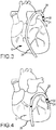
- FIGS 2-4 illustrative views of steerable sheath access device 10 positioned in relation to the epicardial surface of the heart during an ablation procedure are provided.
- FIGs 2-3 illustrate the various degrees of curvature of the proximal sections 26 and distal sections 28 as required during the performance and operation of the sheath access device 10.
- the inner radius of the secondary curve decreases, although at a much lesser degree. Accordingly, as the primary curve is deflected by the tension applying to pull wires provided throughout elongated member 20, this results in the formation of or increase in secondary curve of proximal section 26.
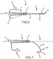
- FIGs 5-7 alternate embodiments of sheath access device 10, shown connected to handle assembly 14 as part of steerable sheath access device assembly 12, are provided.
- Figures 5-7 further disclose an embodiment of a sheath 10 that further includes a plurality of ring electrodes 36 disposed on the outer surface about distal section 28 of elongated member 20.
- Ring electrodes 36 may be provided in a number of combinations and distributed along distal section 28 of elongated member 20, so long as not to prevent or impede the primary curve configured by distal section 28 of sheath 10, as shown in Figure 7 .
- Ring electrodes 36 may be used for mapping or ablation or any other type of procedure that might involve the incorporation of ring electrodes on the outer surface of distal section 28 of sheath 10.
- Ring electrodes 36 may be used for mapping or visualization of the tissue surface such that the information received from the mapping electrodes may be transmitting to a visualization or mapping processor or system, such as those found and used by the ENSTTE ® NavX Navigation and Visualization Technology, referred to as the ENSITE ® system developed by St. Jude Medical, Inc.
- a visualization or mapping processor or system such as those found and used by the ENSTTE ® NavX Navigation and Visualization Technology, referred to as the ENSITE ® system developed by St. Jude Medical, Inc.
- Figure 5 provides a steerable sheath access device assembly 12 having sheath 10 in a fully extended position/configuration. Accordingly, the deflection portion 34 of handle assembly 14 has not been rotated to exert force or tension on the pull wires internal to elongated member.
- traditional handle assemblies used for sheath or other catheter assemblies may be incorporated for use with the present invention. Accordingly, either a unidirectional or a bidirectional handle may be used to control the deflection of sheath 10.
- Figure 6 further provides an alternate view of an embodiment of the present invention including mapping electrodes 36 and further providing an electrical connector 40 for supplying electrical energy to handle assembly 14 and ultimately to mapping electrodes 36 provided on distal section 28 of elongated member 20.
- Figure 7 illustrates the deflection of proximal section 26 and distal section 28 of the sheath 10.
- the distal section 28 may include, for example, one or more mapping electrodes 36.
- the primary curve provided by the deflection of distal section 28 has a smaller (and typically significantly smaller) inner radius than the inner radius corresponding to the secondary curve provided by the deflection of proximal section 26 of elongated member 20 of sheath 10.
- the short access sheath 10 as provided and described above is steerable through the incorporation of and use of pull wires that extend from handle assembly 14, as shown in Figure 1 , through elongated body 20 of sheath 10.
- a single set of pull wires i.e. 2-4 pull wires, are provided and disposed within sheath 10 for deflecting the movement of sheath 10 and creating the primary and secondary curves.
- each pull wire may be separated by from 90-180 degrees from one another and may be integrated within elongated member 20 so as to extend to the region where distal section 28 intersects with distal tip portion 30.
- distal section 28 comprised of a less rigid material deflects at a great angle therein defining a smaller radius of curvature in comparison to the secondary curvature defined by proximal section 26.
- Figures 8-12 illustrate an alternate embodiment of access sheath 10 wherein two sets of pull wires are incorporated within elongated member 20 and positioned to separately acuate deflection of distal section 28 at a primary deflection point (A) and proximal section 26 at a secondary deflection point (B), independently.
- Figure 8 is an illustrative drawing showing sample deflection points (A, B) of access sheath 10 in accordance with an embodiment of the present invention.
- Figure 9 provides a corresponding illustration of pull wires associated with the access sheath in accordance with the embodiment of access sheath 10, for example as shown in Figure 8 .
- the deflection of distal section 28 may be controlled by a primary set of pull wires 42 which extend along elongated member to the distal end of distal section 28.
- Primary pull wires 42 such as shown in Figure 9
- an anchor ring 50 which may be configured as generally shown in Figure 10 .
- a secondary set of pull wires 46 extends along elongated member 20 to at or about the point where distal section 28 intersects with proximal section 26. Secondary pull wires 46 are secured to the elongated member of sheath 10 by an anchor ring 52 as that shown in Figure 11 .
- proximal section 26 may deflect therein to provide a primary curve formed by distal section 28 and a secondary curve formed by proximal section 26.
- distal section 28 includes a material that is comparatively more flexible and is less rigid that the material of proximal section 26.
- primary pull wires 42 to control and acuate the deflection of distal section 28, and secondary set of pull wires 46 control and acuate the deflection of proximal section 26 the inner radius (r 1 ) of curvature of distal section 28 is less than the inner radius of curvature (r 2 , r 3 ) of proximal section 26.
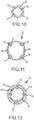
- FIGS 10 and 11 provide illustrative views of the anchor rings 50, 52 used to secure primary pull wires 42 and secondary pull wires 46 within elongated member 20 of sheath 10.
- anchor ring 50 is positioned at distal end 44 of distal section 28.
- Anchor ring 50 is generally cylindrical and may reflect the size and/or shape of elongated member 20 such that anchor ring 50 fits within elongated member and may be reflowed into position once primary pull rings are secured to anchor ring 50 through attachment mechanisms known in the industry.
- anchor ring 52 may comprise a clover-like design and can be provided with recessed grooves 54 for receiving primary pull wires 42 and secondary pull wires 46.
- anchor ring 52 is positioned at the secondary deflection point wherein proximal section 26 intersects with distal section 28.
- pull wires may be stainless steel, such as for example the 304 type, and may be either round or rectangular in cross section.
- nitinol wire may be used as pull wires.
- Figure 12 shows a cross-sectional view of steerable sheath access device 10 in accordance with an embodiment of the present invention as taken along lines 12-12 of Figure 8 at the secondary deflection point.
- the pull wires may, for example, be encased in a polyimide or Teflon guide tubing 56. Secondary pull wires 46 can be secured to anchor ring 52 through various attachment mechanisms as known in the art.
- Access sheath 10 further comprises an outer body 58 thermoplastic material that can be provided in a braided configuration to achieve the flexibility and desired hardness of the proximal and distal sections 26, 28.
- An outer coating of (e.g. PEBAX ® ) may then be provided to create an outer surface 60 of elongated member 20 of sheath 10.
- Access sheath device 10 as previously described in the various embodiments may be provided as part of an assembly or kit which provides and incorporates the use of various tools and devices that correspond or are appropriately configured for a given size of access sheath 10. Because it may be desirable to have a shortened access device, it may be further desirable to include various medical tools that may be inserted within the inner lumen of access sheath 10 for procedures on the epicardial surface of the heart.
- various catheters including RF ablation catheters, such as the medium-sweep Safire cooled directional catheter, may be included to have a shortened catheter shaft (e.g. ranging from 76,2 cm-88,9 cm (30-35 inches) in length, such that the catheter shaft may be readily incorporated within access sheath for performing ablative procedures.
- Other types of energy sources may also be used in connection with access sheath device 10 of the present invention, such as ultrasound (e.g. HIFU), laser, or other energy used for performing ablative procedures.
- Additional electrode tips may be used and configured, such as a closed loop cooled tip, for incorporation with the shorted catheter assembly for insertion within access sheath device 10.
- Additional medical devices for incorporation in the access sheath include a dilator exhibiting an increased softer shaft, similar to the hardness of the material comprising distal section 28 of elongated member 20, described above.
- the dilator may include a blunt nose tip and a shorted shaft.
- the device could include several dilators a rather stiff device which is used to access the pericardial space, a softer tipped device to aid in pericardial navigation and finally a soft blunt tipped dilator which is used to plug sheath when device is left in position for extended periods of time while physician performs endocardial procedure.
- the dilator may further provide a soft closed nosed dilator that may be used after access to the pericardial sac is gained and the access sheath is left in position while other procedures are being performed, in order to aid in keeping pericardial fluid in the area.
- the dilator is provided to open the needle puncture in the pericardium and provide a smooth transition between the guidewire and the sheath outside diameter.
- a Touhy needle may also be used to gain access to the pericardial sac, more particularly for example a 1,15 mm x 11,43 cm (17 ga x 4.5") long needle (e.g. Soda technique).
- a guidewire may also be used, such as a long floppy tip guidewire.
- Each of these components may aid in the physician being able to access and ablation in the pericardial space using radiofrequency techniques, although other energy sources may be used.
- An assembly or kit for use in treating atrial fibrillation through performing ablative procedures on the epicardial surface of the heart may include shortened steerable access sheath device 10, as such described in accordance with the multiple embodiments of the present invention.
Landscapes
- Health & Medical Sciences (AREA)
- Life Sciences & Earth Sciences (AREA)
- Engineering & Computer Science (AREA)
- Surgery (AREA)
- Public Health (AREA)
- Animal Behavior & Ethology (AREA)
- Veterinary Medicine (AREA)
- Biomedical Technology (AREA)
- Heart & Thoracic Surgery (AREA)
- General Health & Medical Sciences (AREA)
- Molecular Biology (AREA)
- Physics & Mathematics (AREA)
- Medical Informatics (AREA)
- Biophysics (AREA)
- Cardiology (AREA)
- Pathology (AREA)
- Otolaryngology (AREA)
- Plasma & Fusion (AREA)
- Nuclear Medicine, Radiotherapy & Molecular Imaging (AREA)
- Physiology (AREA)
- Mechanical Engineering (AREA)
- Pulmonology (AREA)
- Anesthesiology (AREA)
- Hematology (AREA)
- Surgical Instruments (AREA)
- Media Introduction/Drainage Providing Device (AREA)
- Measurement And Recording Of Electrical Phenomena And Electrical Characteristics Of The Living Body (AREA)
- Coupling Device And Connection With Printed Circuit (AREA)
Description
- The present invention relates to a steerable sheath access device or introducer assembly such as those used in epicardial procedures, for the treatment of atrial fibrillation and ventricular tachycardias.
- Many medical procedures require the introduction of specialized medical devices into and/or around the human heart. In particular, there are a number of medical procedures that requires the introduction of specialized devices, including but not limited to catheters, dilators, and needles, to areas such as into the pericardial sac surrounding the heart in order to access the epicardial or outer surface of the heart. Catheters and access sheaths or introducers have been used for medical procedures for a number of years. It is necessary for introducers and catheters to exhibit a degree of flexibility to be able to maneuver through the vasculature of a patient during the performance of cardiac procedures. In additional, various configurations of introducers are necessary for the treatment of different cardiac conditions.
- Atrial fibrillation and ventricular tachycardias are cardiac arrhythmias that result in an irregular heartbeat due to the irregular conduction of electrical impulses to the ventricles of the heart. It is believed that one method of treating atrial fibrillation is through the locating, accessing, stimulating, and ablation of epicardial neuroganglia. It is believed that atrial fibrillation can be controlled more completely by ablating neuroganglia heads located under (or inside) fat pads located on the epicardial surface of the heart. The fat pads are located at the junctions of the pulmonary veins, the inferior vena cava, and in the margin between the aorta and the superior vena cava, all of which may in fact be a major source of fibrillation. Current treatments that involve ablating alternate pathways internal to the heart may be ineffective in truly reaching neuroganlia and instead targets the legs of the neuroganglia, which can necessitate multiple ablations. As a result it is desirable to develop a method of targeting the neuroganlia heads so that the entire circuit can be resolved by ablating the head embedded in or below the fat pad.
- In order to ablate the head of the fat pad located on the epicardial surface, it is necessary to use an ablation catheter that is able to access the epicardial surface of the heart. Traditional approaches to treating atrial fibrillation include the use of introducers or catheter systems that are inserted within the internal chambers of the heart to target areas for ablation. Traditional catheters and access devices, such as introducers, access these endocardial areas through a rigid elongated body that includes a curved portion for accessing areas of the heart and related vasculature for ablation. These traditional catheters and access devices can be too long in length to be used in certain pericardial procedures such as that for potential treatment of atrial fibrillation. Moreover, these traditional devices are not able to be maneuvered or steered to reach the epicardial surfaces for treatment or they may have to be curved throughout the pericardial sac and around the heart to reach the tissue areas of interest.
- A steerable sheath access device for the treatment of atrial fibrillation is known from
US 2005/0234436 A1 . The catheter body of this known device can have any number of flexible segments, such as two, three, four, five, six, etc., at least one of which has a different stiffness than the others. The flexible segments can have any stiffness configuration that allows the catheter to move within the heart or surrounding area. The catheter further comprises a pull wire to deflect its flexible tip. The distal end of the pull wire can be anchored to the wall of the catheter body with the aid of an anchor ring. - The invention is defined in the
independent claim 1. Preferred embodiments are set forth in the dependent claims. Embodiments of the present invention including shorter steerable access sheaths or introducers may provide epicardial access for various ablation tools and devices for the performance of various ablation procedures or procedures involving alternate energy sources. The steerable access device provides an elongated member that exhibits primary and secondary curvatures for access to ablative surfaces or targets. - Accordingly, steerable sheath access device assemblies as provided by the present invention may be provided to enhance and perform the method of ablating epicardial surface for the treatment of atrial fibrillation and ventricular tachycardias.
- The foregoing and other aspects, features, details, utilities, and advantages of embodiments of the present invention will be apparent from reading the following description and claims, and from reviewing the accompanying drawings.
-
-
Figure 1 is an isometric view of steerable sheath access device according to an embodiment of the present invention; -
Figures 2-4 are illustrative views of the steerable sheath access device positioned in relation to the epicardial surface of the heart during an ablation procedure; -
Figure 5 is an isometric view of steerable sheath access device according to an embodiment of the present invention; -
Figure 6 is an isometric view of steerable sheath access device according to an embodiment of the present invention; -
Figure 7 is an isometric view of steerable sheath access device according to an embodiment of the present invention showing the original position of the access sheath in phantom; -
Figure 8 is an illustrative drawing showing the deflection points of the access sheath in accordance with an embodiment of the present invention; -
Figure 9 is an illustrative drawing of pull wires associated with the access sheath in accordance with an embodiment of the present invention; -
Figures 10 and 11 are isometric views of anchor rings provided within a steerable sheath access device in accordance with an embodiment of the present invention; and -
Figure 12 is a cross-sectional view of the steerable sheath access device in accordance with an embodiment of the present invention; - In general, the present invention relates to a steerable short sheath access device assembly for use in epicardial procedures, such as those used for the treatment of atrial fibrillation and ventricular tachycardia. The steerable access device of the assembly provides an elongated member that exhibits primary and secondary curvature for access, for example, to epicardial surfaces for performing ablation. For purposes of this description, similar features among the various embodiments described herein will be referred to by the same reference number. As will be appreciated, however, the structure of the various aspects may differ with respect to alternate embodiments.
- The steerable access device, or introducer, of the assembly according to the present invention may be shorter in length than the traditional access devices to provide more effective access to the epicardial surface of the heart through the pericardial sac. In an embodiment, a steerable access device is comprised of a flexible elongated member that can readily reflect or adapt or conform to the curvature or profile of organs, such as the heart, therein defining a gradual curvature of the sheath for positioning the access device within the pericardial sac and ultimately in relation to the epicardial target surface of the heart for performance of various procedures.
- As generally shown in the embodiment illustrated in
Figure 1 , thesheath access device 10 may comprise part of a steerable sheathaccess device assembly 12. The steerable sheathaccess device assembly 12 may be configured to facilitate access to the epicardial surface of the heart through the pericardial sac. Alternately,assembly 12 may be used, for example, for a number of different procedures. In an embodiment, the steerable sheathaccess device assembly 12 includessheath access device 10 connected to ahandle assembly 14 for controlling the deflection and movement ofdevice 10, and may further include avalve assembly 16 for allowing introduction of medical device components throughaperture 17 accessing inner cavity (not shown) ofhandle assembly 14, as well as astopcock 18 that may be used to restrict the flow of liquid or gas throughassembly 12 or to flush the assembly to disperse trapped air.Figures 2-12 below, describe alternate embodiments and illustrate exemplary applications ofsheath access device 10. - As generally illustrated in
Figure 1 ,sheath access device 10 is connected to handleassembly 14 as part of steerable sheathaccess device assembly 12.Sheath access device 10, also often referred to as an introducer, comprises anelongated member 20. Elongatedmember 20 includes aproximal end 22 and adistal end 24. Elongatedmember 20 further includes aninner lumen 32, e.g. as shown inFigures 2-4 , that provides for the insertion and positioning of various medical tools and devices, including but not limited to, catheters, dilators, electrode tips for ablation, needles, and guide wires. Accesssheath 10 facilitates the introduction and positioning of devices to establish contact with targeted tissue areas, such as the epicardial surface of the heart within the pericardial sac. Elongatedmember 20 further includes aproximal section 26 and adistal section 28.Proximal section 26 anddistal section 28 may be integral with one another therein providing a single unitaryelongated member 20. Moreover,proximal section 26 is positioned more distally with respect toproximal end 22 ofelongated member 20 anddistal section 28 is positioned more distally with respect toproximal section 26 ofelongated member 20. Portions ofproximal section 26 anddistal section 28 intersect with one another and the components form aunitary sheath 10. Elongatedmember 10 further includes adistal tip portion 30.Distal tip portion 30 is provided yet further distally with respect todistal section 28 and extends todistal tip 24 ofelongated member 20.Distal tip portion 30 may be tapered to form a desirable transition with devices that may be inserted through the inner lumen ofelongated member 20.Distal tip 24 may be chamfered to provide a smooth transition end toelongated member 20 ofsheath 10 and further provides an outlet for the inner lumen, so that the dilators, catheters, or other devices may exitsheath 10. -
Sheath 10 is generally comprised of a biocompatible polymer material that exhibits various degrees of flexibility and rigidity, depending on the design and performance requirements. In an embodiment, elongatedmember 20 ofsheath 10 is comprised of a thermoplastic material, such as, without limitation, PEBAX®. Throughout the length ofelongated member 20 various materials such as thermoplastics (e.g. PEBAX®) that exhibit different degrees of hardness (or durometer) may be used. In addition, the material made be braided or provided in alternate configurations to achieve a desired degree or measure of rigidity and/or flexibility. The device may also be lined with Teflon in order to reduce friction during insertion of various instruments. In an embodiment,proximal section 26 is made of a different material than the material comprisingdistal section 28, such that the hardness or durometer ofproximal section 26 is greater than the hardness or durometer ofdistal section 28. According to an embodiment of the present invention,proximal section 26 may include a hardness/rigidity within the range of 50-70 durometer. For some embodiments the range may be 55-65 durometer.Distal section 28 includes a hardness/rigidity within the range of 35-45 durometer, and may, for example, be about a 40 durometer. In another embodiment,distal tip portion 30 is made of material, such that the hardness/rigidity ofdistal tip portion 30 is even less thandistal section 28. This softness or flexibility can be provided to prevent damage to the pericardial sac and epicardial surface of the heart. Accordingly,distal tip portion 30 may have a hardness/rigidity within the range of 20-30 durometer, and for some embodiments may be approximately 25 durometer. In alternate embodiments, various sections ofelongated member 20 may be radiopaque or include various fluorescent markers such that the access sheath is visible through fluoroscopy. - Variations in size and shape of
sheath 10 may be used and are intended to encompass all applicable uses, including use on pediatric patients, as well as in adult human hearts. It is recognized that based on the application ofdevice 10, the length ofelongated member 20 may vary slightly to reflect the size of the patient being treated.Sheath 10, in accordance with the present invention, is generally 30,5 cm-43,2 cm (12-17 inches) in length. For some embodiments,sheath 10 may be about 43,2 cm (17 inches) in length. Accordingly, the length ofproximal section 26 ranges from about 34,3 cm (13.5 inche) to about 39,4 cm (15.5 inches. For some embodiments,proximal section 26 is approximately 36,8 ± 1,3 cm (14.5 ± 0.5 inches) in length.Distal section 28 ranges from about 3,8 cm (1.5 inches) to about 8,9 cm (3.5 inches). For some embodiments,distal section 28 is approximately 6,4 cm±0,3 cm (2.5±0.1 inches) in length. Slight variations may be made to the length depending on the design or manufacturing of the system.Distal tip portion 30 is further provided and is only approximately 3,75 mm-3,683 mm (0.125-0.145 inches) in length. For some embodiments,distal tip portion 30 is about 3,683 mm (0.145 inches) in length. - As further seen in
Figure 1 and in accordance with an embodiment of the present invention,sheath 10 includes two curves as provided byproximal section 26 anddistal section 28 ofelongated member 20. The curvatures may be created or formed via either one set or a plurality of sets of pull wires that run or extend along the length ofelongated member 20 and are controlled by mechanisms provided withinhandle assembly 14. In one embodiment, for example, as shown inFigure 1 ,distal section 28 may include a primary curve that has an inner radius (r1) that ranges from about 0.5 to about 2.0 centimeters depending on the deflection forces created or imparted by the user through the use ofhandle assembly 14. In an embodiment, the inner radius (r1) is about 1.0 centimeters.Proximal section 26 further defines a secondary curve that includes an inner radius (r2) that is substantially greater than the inner radius of the primary curve ofdistal section 28. As seen inFigure 1 , secondary curve may also further includes a second inner radius (r3) as further provided by a portion of the secondary curve. The arc or overall curve of the secondary curve ofproximal section 26 may vary slight such that multiple radi (r) may define the radius of curvature of the secondary curve. Overall, and in accordance with the embodiments of the present invention, the inner radi (r2, r3) of the secondary curve provided byproximal section 26 are each substantially greater than (e.g., at least 3, 4, or more times) the inner radius (r1) of the primary curve provided bydistal section 28. - As seen in
Figures 2-4 , illustrative views of steerablesheath access device 10 positioned in relation to the epicardial surface of the heart during an ablation procedure are provided. Each of the Figures illustrate the various degrees of curvature of theproximal sections 26 anddistal sections 28 as required during the performance and operation of thesheath access device 10. As can further be seen in comparingFigures 2-3 withFigure 4 , as the inner radius of the primary curve decreases and creates a tighter curve, the inner radius of the secondary curve also decreases, although at a much lesser degree. Accordingly, as the primary curve is deflected by the tension applying to pull wires provided throughoutelongated member 20, this results in the formation of or increase in secondary curve ofproximal section 26. - In
Figures 5-7 , alternate embodiments ofsheath access device 10, shown connected to handleassembly 14 as part of steerable sheathaccess device assembly 12, are provided.Figures 5-7 further disclose an embodiment of asheath 10 that further includes a plurality ofring electrodes 36 disposed on the outer surface aboutdistal section 28 ofelongated member 20.Ring electrodes 36 may be provided in a number of combinations and distributed alongdistal section 28 ofelongated member 20, so long as not to prevent or impede the primary curve configured bydistal section 28 ofsheath 10, as shown inFigure 7 .Ring electrodes 36 may be used for mapping or ablation or any other type of procedure that might involve the incorporation of ring electrodes on the outer surface ofdistal section 28 ofsheath 10.Ring electrodes 36 may be used for mapping or visualization of the tissue surface such that the information received from the mapping electrodes may be transmitting to a visualization or mapping processor or system, such as those found and used by the ENSTTE® NavX Navigation and Visualization Technology, referred to as the ENSITE® system developed by St. Jude Medical, Inc. -
Figure 5 provides a steerable sheathaccess device assembly 12 havingsheath 10 in a fully extended position/configuration. Accordingly, thedeflection portion 34 ofhandle assembly 14 has not been rotated to exert force or tension on the pull wires internal to elongated member. Overall, traditional handle assemblies used for sheath or other catheter assemblies may be incorporated for use with the present invention. Accordingly, either a unidirectional or a bidirectional handle may be used to control the deflection ofsheath 10. -
Figure 6 further provides an alternate view of an embodiment of the present invention includingmapping electrodes 36 and further providing anelectrical connector 40 for supplying electrical energy to handleassembly 14 and ultimately tomapping electrodes 36 provided ondistal section 28 ofelongated member 20. -
Figure 7 illustrates the deflection ofproximal section 26 anddistal section 28 of thesheath 10. Thedistal section 28 may include, for example, one ormore mapping electrodes 36. In accordance with an embodiment of the present invention, the primary curve provided by the deflection ofdistal section 28 has a smaller (and typically significantly smaller) inner radius than the inner radius corresponding to the secondary curve provided by the deflection ofproximal section 26 ofelongated member 20 ofsheath 10. - The
short access sheath 10 as provided and described above is steerable through the incorporation of and use of pull wires that extend fromhandle assembly 14, as shown inFigure 1 , throughelongated body 20 ofsheath 10. In one embodiment, a single set of pull wires, i.e. 2-4 pull wires, are provided and disposed withinsheath 10 for deflecting the movement ofsheath 10 and creating the primary and secondary curves. In an embodiment, each pull wire may be separated by from 90-180 degrees from one another and may be integrated withinelongated member 20 so as to extend to the region wheredistal section 28 intersects withdistal tip portion 30. Accordingly, as rotation force fromdeflection member 34 ofhandle assembly 14 is applied, the pull wires undergo force which results in the deflection ofproximal section 26 anddistal section 28. Upon the application of force on the distal ends of pull wires, provided withindistal section 28 ofsheath 10,distal section 28 comprised of a less rigid material deflects at a great angle therein defining a smaller radius of curvature in comparison to the secondary curvature defined byproximal section 26. -
Figures 8-12 illustrate an alternate embodiment ofaccess sheath 10 wherein two sets of pull wires are incorporated within elongatedmember 20 and positioned to separately acuate deflection ofdistal section 28 at a primary deflection point (A) andproximal section 26 at a secondary deflection point (B), independently. In particular,Figure 8 is an illustrative drawing showing sample deflection points (A, B) ofaccess sheath 10 in accordance with an embodiment of the present invention. Moreover,Figure 9 provides a corresponding illustration of pull wires associated with the access sheath in accordance with the embodiment ofaccess sheath 10, for example as shown inFigure 8 . The deflection ofdistal section 28 may be controlled by a primary set ofpull wires 42 which extend along elongated member to the distal end ofdistal section 28.Primary pull wires 42, such as shown inFigure 9 , are secured todistal end 44 ofdistal section 28 by ananchor ring 50, which may be configured as generally shown inFigure 10 . A secondary set ofpull wires 46 extends alongelongated member 20 to at or about the point wheredistal section 28 intersects withproximal section 26.Secondary pull wires 46 are secured to the elongated member ofsheath 10 by ananchor ring 52 as that shown inFigure 11 . Although onlydistal section 28 is shown as deflected inFigure 8 ,proximal section 26 may deflect therein to provide a primary curve formed bydistal section 28 and a secondary curve formed byproximal section 26. As previously described,distal section 28 includes a material that is comparatively more flexible and is less rigid that the material ofproximal section 26. As a result, even withprimary pull wires 42 to control and acuate the deflection ofdistal section 28, and secondary set ofpull wires 46 control and acuate the deflection ofproximal section 26, the inner radius (r1) of curvature ofdistal section 28 is less than the inner radius of curvature (r2, r3) ofproximal section 26. -
Figures 10 and 11 provide illustrative views of the anchor rings 50, 52 used to secureprimary pull wires 42 andsecondary pull wires 46 withinelongated member 20 ofsheath 10. As previously discussed,anchor ring 50 is positioned atdistal end 44 ofdistal section 28.Anchor ring 50 is generally cylindrical and may reflect the size and/or shape ofelongated member 20 such thatanchor ring 50 fits within elongated member and may be reflowed into position once primary pull rings are secured to anchorring 50 through attachment mechanisms known in the industry. As seen inFigure 11 ,anchor ring 52 may comprise a clover-like design and can be provided with recessedgrooves 54 for receivingprimary pull wires 42 andsecondary pull wires 46. In anembodiment anchor ring 52 is positioned at the secondary deflection point whereinproximal section 26 intersects withdistal section 28. In one embodiment, pull wires may be stainless steel, such as for example the 304 type, and may be either round or rectangular in cross section. In another embodiment, nitinol wire may be used as pull wires. -
Figure 12 shows a cross-sectional view of steerablesheath access device 10 in accordance with an embodiment of the present invention as taken along lines 12-12 ofFigure 8 at the secondary deflection point. The pull wires may, for example, be encased in a polyimide orTeflon guide tubing 56.Secondary pull wires 46 can be secured to anchorring 52 through various attachment mechanisms as known in the art.Access sheath 10 further comprises anouter body 58 thermoplastic material that can be provided in a braided configuration to achieve the flexibility and desired hardness of the proximal anddistal sections outer surface 60 ofelongated member 20 ofsheath 10. -
Access sheath device 10 as previously described in the various embodiments may be provided as part of an assembly or kit which provides and incorporates the use of various tools and devices that correspond or are appropriately configured for a given size ofaccess sheath 10. Because it may be desirable to have a shortened access device, it may be further desirable to include various medical tools that may be inserted within the inner lumen ofaccess sheath 10 for procedures on the epicardial surface of the heart. - In particular, various catheters, including RF ablation catheters, such as the medium-sweep Safire cooled directional catheter, may be included to have a shortened catheter shaft (e.g. ranging from 76,2 cm-88,9 cm (30-35 inches) in length, such that the catheter shaft may be readily incorporated within access sheath for performing ablative procedures. Other types of energy sources may also be used in connection with
access sheath device 10 of the present invention, such as ultrasound (e.g. HIFU), laser, or other energy used for performing ablative procedures. Additional electrode tips may be used and configured, such as a closed loop cooled tip, for incorporation with the shorted catheter assembly for insertion withinaccess sheath device 10. - Additional medical devices for incorporation in the access sheath include a dilator exhibiting an increased softer shaft, similar to the hardness of the material comprising
distal section 28 ofelongated member 20, described above. The dilator may include a blunt nose tip and a shorted shaft. The device could include several dilators a rather stiff device which is used to access the pericardial space, a softer tipped device to aid in pericardial navigation and finally a soft blunt tipped dilator which is used to plug sheath when device is left in position for extended periods of time while physician performs endocardial procedure. The dilator may further provide a soft closed nosed dilator that may be used after access to the pericardial sac is gained and the access sheath is left in position while other procedures are being performed, in order to aid in keeping pericardial fluid in the area. In an embodiment, the dilator is provided to open the needle puncture in the pericardium and provide a smooth transition between the guidewire and the sheath outside diameter. - A Touhy needle may also be used to gain access to the pericardial sac, more particularly for example a 1,15 mm x 11,43 cm (17 ga x 4.5") long needle (e.g. Soda technique). A guidewire may also be used, such as a long floppy tip guidewire. Each of these components may aid in the physician being able to access and ablation in the pericardial space using radiofrequency techniques, although other energy sources may be used.
- An assembly or kit for use in treating atrial fibrillation through performing ablative procedures on the epicardial surface of the heart may include shortened steerable
access sheath device 10, as such described in accordance with the multiple embodiments of the present invention. - Although a number of embodiments of this invention have been described above with a certain degree of particularity, those skilled in the art could make numerous alterations to the disclosed embodiments without departing from the scope of this invention. All directional references (e.g., upper, lower, upward, downward, left, right, leftward, rightward, top, bottom, above, below, vertical, horizontal, clockwise, and counterclockwise) are only used for identification purposes to aid the reader's understanding of the present invention, and do not create limitations, particularly as to the position, orientation, or use of the invention. Joinder references (e.g., attached, coupled, connected, and the like) are to be construed broadly and may include intermediate members between a connection of elements and relative movement between elements. As such, joinder references do not necessarily infer that two elements are directly connected and in fixed relation to each other. It is intended that all matter contained in the above description or shown in the accompanying drawings shall be interpreted as illustrative only and not limiting.
Claims (15)
- A steerable sheath access device assembly (12), comprising
a handle assembly (14), and
a sheath access device (10), comprising:an elongated member (20) having a proximal end (22), a distal end (24), and a lumen (32) extending through the elongated member (20) from the proximal end (22) to the distal end (24); the elongated member (20) having a proximal section (26) made of a first material and a distal section (28) made of a second material, the proximal section (26) extending from the proximal end (22) to an intersection of the proximal section (26) and the distal section (28), and the distal section (28) extending from the intersection of the proximal section (26) and the distal section (28) to the distal end (24), wherein the handle assembly (14) is connected to the proximal end (22) of the elongated member (20),a primary pull wire (42) connected to the elongated member (20), the primary pull wire (42) extending along the length of the elongated member (20) from the handle assembly to a first anchor ring (50) at a distal end of the distal section (28), wherein the first anchor ring (50) is provided at least in part within the lumen of the elongated member (20), anda secondary pull wire (46) connected to the elongated member (20), the secondary pull wire (46) extending along the length of the elongated member (20) from the handle assembly to a second anchor ring (52) at the intersection of the proximal section (26) and the distal section (28),wherein the second anchor ring (52) is provided at least in part within the lumen of the elongated member (20), wherein the first material of the proximal section (26) is more rigid than the second material of the distal section (28);wherein the elongated member (20) is configured such that deflection of the distal section (28) defines a primary curve including a first inner radius (r1) of curvature, wherein the elongated member (20) is configured such that deflection of the proximal section (26) defines a secondary curve including a second inner radius (r2, r3) of curvature, and wherein the first inner radius (r1) of curvature of the primary curve is less than the second inner radius (r2, r3) of curvature of the secondary curve. - The assembly (12) of claim 1, wherein the distal section (28) has a hardness less than the hardness of the proximal section (26).
- The assembly (12) of claim 1 or 2, including a tip portion (30) disposed on the distal end of the distal section (28).
- The assembly (12) of claim 3, wherein the tip portion (30) is less rigid than the proximal section (26) and distal section (28) of the elongated member (20).
- The assembly (12) of any one of the preceding claims, wherein the length of the elongated member (20) ranges from about 30,5 cm to about 43,2 cm (12 to about 17 inches).
- The assembly (12) of any one of the preceding claims, wherein the length of the proximal section (26) is 36,8 ± 1,3 cm (14.5 ± 0.5 inches).
- The assembly (12) of any one of the preceding claims, wherein the length of the distal section (28) ranges from about 3,8 cm (1.5 cm inches) to about 8,9 cm (3.5 inches).
- The assembly (12) of claim 5, wherein the length of the distal section (28) is 6,4 cm ± 0,3 cm (2.5 ± 0.1 inches).
- The assembly (12) of any one of the preceding claims, wherein a plurality of primary pull wires (42) is provided and the second anchor ring (52) includes a plurality of depressions (54) for receiving the primary pull wires (42) an exterior surface of the second anchor ring (52).
- The assembly (12) of any one of the preceding claims, wherein a plurality of secondary pull wires (46) is provided and the secondary pull wires (46) are connected to an interior portion of the second anchor ring (52).
- The assembly (12) of any one of the preceding claims, wherein the elongated member (20) is comprised of a thermoplastic.
- The assembly (12) of any one of the preceding claims, wherein the arc length of the secondary curve of the proximal section (26) is longer than the arc length of the primary curve of the distal section (28).
- The assembly (12) of any one of the preceding claims, including an electrode (36) connected to the distal section (28) of the elongated member (20).
- The assembly (12) according to any one of the previous claims;
wherein the handle assembly (14) includes an outer body portion having a proximal end and a distal end, the distal end of the assembly is coupled to the proximal end (22) of the elongated member (20), the handle assembly further including a deflection handle portion for controlling the deflection and movement of the elongated member (20) and an inner cavity extending along the length of the handle assembly; and
wherein the assembly (12) further comprises a valve assembly (16) having an opening coupled to the inner cavity of the handle assembly (14) and the lumen (32) of the elongated member (20) therein providing a passageway. - An ablation assembly for use in performing ablation procedures, comprising:steerable sheath access device assembly (12) according to claim 14;a dilator for insertion into the passageway defined by the steerable sheath access device assembly (12);an ablation catheter comprising a catheter shaft and an ablation electrode for insertion into the passageway defined by the steerable sheath access device assembly (12);a needle for insertion through the steerable sheath access device (10); anda guidewire for use in positioning the steerable sheath access device assembly (12).
Applications Claiming Priority (2)
| Application Number | Priority Date | Filing Date | Title |
|---|---|---|---|
| US82893906P | 2006-10-10 | 2006-10-10 | |
| PCT/US2007/080939 WO2008045936A2 (en) | 2006-10-10 | 2007-10-10 | Steerable short sheath access device |
Publications (3)
| Publication Number | Publication Date |
|---|---|
| EP2073737A2 EP2073737A2 (en) | 2009-07-01 |
| EP2073737A4 EP2073737A4 (en) | 2011-07-13 |
| EP2073737B1 true EP2073737B1 (en) | 2016-12-21 |
Family
ID=39283575
Family Applications (3)
| Application Number | Title | Priority Date | Filing Date |
|---|---|---|---|
| EP07844081.5A Active EP2073737B1 (en) | 2006-10-10 | 2007-10-10 | Steerable sheath access device assembly |
| EP15159972.7A Not-in-force EP2898848B1 (en) | 2006-10-10 | 2007-10-10 | Catheter or sheath comprising a circuit |
| EP07844086.4A Not-in-force EP2068738B1 (en) | 2006-10-10 | 2007-10-10 | Circuit for a catheter or sheath |
Family Applications After (2)
| Application Number | Title | Priority Date | Filing Date |
|---|---|---|---|
| EP15159972.7A Not-in-force EP2898848B1 (en) | 2006-10-10 | 2007-10-10 | Catheter or sheath comprising a circuit |
| EP07844086.4A Not-in-force EP2068738B1 (en) | 2006-10-10 | 2007-10-10 | Circuit for a catheter or sheath |
Country Status (3)
| Country | Link |
|---|---|
| US (7) | US8968299B2 (en) |
| EP (3) | EP2073737B1 (en) |
| WO (4) | WO2008045877A2 (en) |
Families Citing this family (160)
| Publication number | Priority date | Publication date | Assignee | Title |
|---|---|---|---|---|
| JP4511935B2 (en) | 2002-08-24 | 2010-07-28 | サブラマニアム シー. クリシュナン | Transseptal puncture device |
| CA2932956C (en) | 2006-08-03 | 2020-04-14 | Christoph Scharf | Method and device for determining and presenting surface charge and dipole densities on cardiac walls |
| WO2008045877A2 (en) | 2006-10-10 | 2008-04-17 | St. Jude Medical, Atrial Fibrillation Division, Inc. | Electrode tip and ablation system |
| WO2008092246A1 (en) | 2007-01-29 | 2008-08-07 | Simon Fraser University | Transvascular nerve stimulation apparatus and methods |
| US8979837B2 (en) | 2007-04-04 | 2015-03-17 | St. Jude Medical, Atrial Fibrillation Division, Inc. | Flexible tip catheter with extended fluid lumen |
| US8517999B2 (en) | 2007-04-04 | 2013-08-27 | St. Jude Medical, Atrial Fibrillation Division, Inc. | Irrigated catheter with improved fluid flow |
| US8764742B2 (en) | 2007-04-04 | 2014-07-01 | St. Jude Medical, Atrial Fibrillation Division, Inc. | Irrigated catheter |
| US8974454B2 (en) | 2009-12-31 | 2015-03-10 | St. Jude Medical, Atrial Fibrillation Division, Inc. | Kit for non-invasive electrophysiology procedures and method of its use |
| US11395694B2 (en) * | 2009-05-07 | 2022-07-26 | St. Jude Medical, Llc | Irrigated ablation catheter with multiple segmented ablation electrodes |
| US10220187B2 (en) | 2010-06-16 | 2019-03-05 | St. Jude Medical, Llc | Ablation catheter having flexible tip with multiple flexible electrode segments |
| US10660690B2 (en) | 2007-12-28 | 2020-05-26 | St. Jude Medical, Atrial Fibrillation Division, Inc. | System and method for measurement of an impedance using a catheter such as an ablation catheter |
| US8512255B2 (en) | 2008-01-17 | 2013-08-20 | Christoph Scharf | Device and method for the geometric determination of electrical dipole densities on the cardiac wall |
| US9339331B2 (en) | 2008-12-29 | 2016-05-17 | St. Jude Medical, Atrial Fibrillation Division, Inc. | Non-contact electrode basket catheters with irrigation |
| US20100168717A1 (en) * | 2008-12-30 | 2010-07-01 | Grasse Martin M | Multi-lumen medical devices and methods of manufacturing same |
| SE0901166A1 (en) * | 2009-09-10 | 2011-03-11 | Cathprint Ab | Flexible catheter lead carrier provided with such lead carrier |
| US8906013B2 (en) | 2010-04-09 | 2014-12-09 | Endosense Sa | Control handle for a contact force ablation catheter |
| US9918787B2 (en) | 2010-05-05 | 2018-03-20 | St. Jude Medical, Atrial Fibrillation Division, Inc. | Monitoring, managing and/or protecting system and method for non-targeted tissue |
| US9173705B2 (en) | 2010-05-13 | 2015-11-03 | Ncontact Surgical, Inc. | Subxyphoid epicardial ablation |
| US20120130217A1 (en) * | 2010-11-23 | 2012-05-24 | Kauphusman James V | Medical devices having electrodes mounted thereon and methods of manufacturing therefor |
| US8696620B2 (en) | 2010-07-30 | 2014-04-15 | St. Jude Medical, Atrial Fibrillation Division, Inc. | Catheter with a mechanism for omni-directional deflection of a catheter shaft |
| US9028417B2 (en) | 2010-10-18 | 2015-05-12 | CardioSonic Ltd. | Ultrasound emission element |
| US20130218068A1 (en) | 2010-10-18 | 2013-08-22 | CardioSonic Ltd. | Therapeutics reservoir |
| US20120095371A1 (en) | 2010-10-18 | 2012-04-19 | CardioSonic Ltd. | Ultrasound transducer and cooling thereof |
| US9566456B2 (en) * | 2010-10-18 | 2017-02-14 | CardioSonic Ltd. | Ultrasound transceiver and cooling thereof |
| US9572508B2 (en) | 2010-11-09 | 2017-02-21 | St. Jude Medical, Atrial Fibrillation Division, Inc. | In-plane dual loop fixed diameter electrophysiology catheters and methods of manufacturing therefor |
| WO2012068273A1 (en) | 2010-11-16 | 2012-05-24 | Tva Medical, Inc. | Devices and methods for forming a fistula |
| US8560086B2 (en) | 2010-12-02 | 2013-10-15 | St. Jude Medical, Atrial Fibrillation Division, Inc. | Catheter electrode assemblies and methods of construction therefor |
| EP2667811B1 (en) | 2011-01-27 | 2015-12-30 | Cryosa, Llc | Apparatus for treatment of obstructive sleep apnea utilizing cryolysis of adipose tissues |
| EP2677961B1 (en) | 2011-02-24 | 2024-12-11 | Eximo Medical Ltd. | Hybrid catheter for vascular intervention |
| AU2012225250B2 (en) | 2011-03-10 | 2016-12-08 | Enchannel Medical, Ltd. | Device and method for the geometric determination of electrical dipole densities on the cardiac wall |
| US8858548B2 (en) | 2011-03-15 | 2014-10-14 | Medtronic Ablation Frontiers Llc | Independent passive cooling design for ablation catheters |
| EP3498208A1 (en) | 2011-04-12 | 2019-06-19 | Thermedical, Inc. | Devices for heating fluid in fluid enhanced ablation therapy |
| EP2699153B1 (en) * | 2011-04-22 | 2015-12-16 | Topera, Inc. | Flexible electrode assembly for insertion into body lumen or organ |
| US20130090647A1 (en) * | 2011-10-11 | 2013-04-11 | Boston Scientific Scimed, Inc. | Ablation catheter with insulated tip |
| CN104254366B (en) | 2011-12-09 | 2017-03-08 | 麦特文申公司 | Devices, systems and methods for neuromodulation |
| EP2822645B1 (en) | 2012-03-05 | 2017-05-03 | Simon Fraser University | Transvascular nerve stimulation apparatus |
| WO2013134543A1 (en) | 2012-03-08 | 2013-09-12 | Medtronic Ardian Luxembourg Sarl | Immune system neuromodulation and associated systems and methods |
| US10357304B2 (en) | 2012-04-18 | 2019-07-23 | CardioSonic Ltd. | Tissue treatment |
| US8702647B2 (en) * | 2012-04-19 | 2014-04-22 | Medtronic Ablation Frontiers Llc | Catheter deflection anchor |
| US11357447B2 (en) | 2012-05-31 | 2022-06-14 | Sonivie Ltd. | Method and/or apparatus for measuring renal denervation effectiveness |
| JP6359528B2 (en) | 2012-06-21 | 2018-07-18 | ラングペーサー メディカル インコーポレイテッドLungpacer Medical Inc. | Transvascular diaphragm pacing system and method of use |
| US10022176B2 (en) | 2012-08-15 | 2018-07-17 | Thermedical, Inc. | Low profile fluid enhanced ablation therapy devices and methods |
| CA2881457C (en) | 2012-08-31 | 2021-10-26 | Acutus Medical, Inc. | Catheter system and methods of medical uses of same, including diagnostic and treatment uses for the heart |
| WO2014059351A1 (en) | 2012-10-11 | 2014-04-17 | Tva Medical, Inc. | Devices and methods for fistula formation |
| US9717141B1 (en) * | 2013-01-03 | 2017-07-25 | St. Jude Medical, Atrial Fibrillation Division, Inc. | Flexible printed circuit with removable testing portion |
| US20140200639A1 (en) | 2013-01-16 | 2014-07-17 | Advanced Neuromodulation Systems, Inc. | Self-expanding neurostimulation leads having broad multi-electrode arrays |
| US12514456B2 (en) | 2013-01-31 | 2026-01-06 | Eximo Medical Ltd. | System and methods for lesion characterization in blood vessels |
| EP2953550B1 (en) * | 2013-02-08 | 2020-05-20 | Acutus Medical, Inc. | Expandable catheter assembly with flexible printed circuit board |
| US9179971B2 (en) | 2013-02-11 | 2015-11-10 | St. Jude Medical, Atrial Fibrillation Division, Inc. | Printed electrode catheter |
| EP3566740B1 (en) | 2013-03-14 | 2024-08-14 | TVA Medical, Inc. | Fistula formulation/formation devices |
| US9033972B2 (en) | 2013-03-15 | 2015-05-19 | Thermedical, Inc. | Methods and devices for fluid enhanced microwave ablation therapy |
| US9610396B2 (en) | 2013-03-15 | 2017-04-04 | Thermedical, Inc. | Systems and methods for visualizing fluid enhanced ablation therapy |
| US10933259B2 (en) | 2013-05-23 | 2021-03-02 | CardioSonic Ltd. | Devices and methods for renal denervation and assessment thereof |
| CN105473089A (en) | 2013-06-05 | 2016-04-06 | 麦特文申公司 | Modulation of targeted nerve fibers |
| EP2818104B1 (en) * | 2013-06-25 | 2016-01-06 | VascoMed GmbH | Catheter and method for producing same |
| US10828011B2 (en) | 2013-09-13 | 2020-11-10 | Acutus Medical, Inc. | Devices and methods for determination of electrical dipole densities on a cardiac surface |
| WO2015042900A1 (en) | 2013-09-29 | 2015-04-02 | Covidien Lp | Medical treatment devices having adjustable length and/or diameter |
| WO2015042906A1 (en) | 2013-09-29 | 2015-04-02 | Covidien Lp | Medical treatment devices having adjustable length and/or diameter |
| EP3071280B1 (en) * | 2013-11-18 | 2020-06-24 | Koninklijke Philips N.V. | Treatment catheter including therapeutic energy delivery |
| CN105873630B (en) | 2013-11-22 | 2020-01-03 | 隆佩瑟尔医疗公司 | Device and method for assisted respiration by transvascular nerve stimulation |
| US20160324564A1 (en) * | 2013-12-27 | 2016-11-10 | Empire Technology Development Llc | Devices and techniques for ablative treatment |
| EP3566743B1 (en) | 2014-01-21 | 2021-03-10 | Lungpacer Medical Inc. | Systems for optimization of multi-electrode nerve pacing |
| EP3079580B1 (en) | 2014-01-28 | 2017-11-22 | St. Jude Medical International Holding S.à r.l. | Medical device with a packaged electronic subassembly and method for fabricating the same |
| EP3082588B8 (en) * | 2014-01-28 | 2018-12-19 | St. Jude Medical International Holding S.à r.l. | Elongate medical devices incorporating a flexible substrate, a sensor, and electrically-conductive traces |
| JP6419214B2 (en) | 2014-01-28 | 2018-11-07 | セント・ジュード・メディカル,カーディオロジー・ディヴィジョン,インコーポレイテッド | Catheter shaft with conductive traces |
| US10695534B2 (en) | 2014-03-14 | 2020-06-30 | Tva Medical, Inc. | Fistula formation devices and methods therefor |
| EP3122246B1 (en) | 2014-03-25 | 2022-05-04 | Acutus Medical, Inc. | Cardiac analysis user interface system and method |
| US10219702B2 (en) | 2014-03-26 | 2019-03-05 | St. Jude Medical, Cardiology Division, Inc. | Single fiber force-sensing of both axial and bending catheter tip forces |
| US11826172B2 (en) | 2014-05-06 | 2023-11-28 | St. Jude Medical, Cardiology Division, Inc. | Electrode support structure assembly |
| US10118022B2 (en) | 2014-06-05 | 2018-11-06 | St. Jude Medical, Cardiology Division, Inc. | Deflectable catheter shaft section |
| US9844645B2 (en) | 2014-06-17 | 2017-12-19 | St. Jude Medical, Cardiology Division, Inc. | Triple coil catheter support |
| JP6229077B2 (en) * | 2014-07-11 | 2017-11-08 | ボストン サイエンティフィック サイムド,インコーポレイテッドBoston Scientific Scimed,Inc. | Ablation medical devices |
| WO2016033374A1 (en) | 2014-08-27 | 2016-03-03 | Tva Medical, Inc. | Cryolipopysis devices and methods therefor |
| US10898096B2 (en) | 2014-10-27 | 2021-01-26 | St. Jude Medical, Cardiology Division, Inc. | Apparatus and method for connecting elements in medical devices |
| JP6825789B2 (en) | 2014-11-19 | 2021-02-03 | エピックス セラピューティクス,インコーポレイテッド | Systems and methods for high resolution mapping of tissues |
| AU2015349961A1 (en) | 2014-11-19 | 2017-06-29 | Epix Therapeutics, Inc. | Ablation devices, systems and methods of using a high-resolution electrode assembly |
| EP3220841B1 (en) | 2014-11-19 | 2023-01-25 | EPiX Therapeutics, Inc. | High-resolution mapping of tissue with pacing |
| US20190069949A1 (en) | 2014-12-03 | 2019-03-07 | Metavention, Inc. | Systems and methods for modulatng nerves or other tissue |
| WO2016123390A1 (en) | 2015-01-28 | 2016-08-04 | St. Jude Medical, Cardiology Division, Inc. | Thermal mapping catheter |
| US10603040B1 (en) | 2015-02-09 | 2020-03-31 | Tva Medical, Inc. | Methods for treating hypertension and reducing blood pressure with formation of fistula |
| US20160228061A1 (en) * | 2015-02-10 | 2016-08-11 | Cathprint Ab | Low profile medical device with integrated flexible circuit and methods of making the same |
| US20160270732A1 (en) * | 2015-03-17 | 2016-09-22 | Cathprint Ab | Low profile medical device with bonded base for electrical components |
| EP3256201B1 (en) * | 2015-02-10 | 2024-05-22 | Cathprint AB | Low profile medical device with integrated flexible circuit and methods of making the same |
| US9636164B2 (en) | 2015-03-25 | 2017-05-02 | Advanced Cardiac Therapeutics, Inc. | Contact sensing systems and methods |
| US10602983B2 (en) | 2015-05-08 | 2020-03-31 | St. Jude Medical International Holding S.À R.L. | Integrated sensors for medical devices and method of making integrated sensors for medical devices |
| WO2016183285A1 (en) | 2015-05-12 | 2016-11-17 | Acutus Medical, Inc. | Ultrasound sequencing system and method |
| WO2016183179A1 (en) | 2015-05-12 | 2016-11-17 | Acutus Medical, Inc. | Cardiac virtualization test tank and testing system and method |
| CA2984929A1 (en) | 2015-05-13 | 2016-11-17 | Acutus Medical, Inc. | Localization system and method useful in the acquisition and analysis of cardiac information |
| CN107614049B (en) | 2015-05-29 | 2021-06-04 | 微仙美国有限公司 | catheter circuit |
| EP3791820B9 (en) | 2015-10-21 | 2022-04-27 | St. Jude Medical, Cardiology Division, Inc. | High density electrode mapping catheter |
| EP3834759B1 (en) | 2015-10-21 | 2023-04-05 | St. Jude Medical, Cardiology Division, Inc. | High density electrode mapping catheter |
| WO2017117560A1 (en) | 2015-12-30 | 2017-07-06 | Pipeline Medical Technologies, Inc. | Mitral leaflet tethering |
| US10874422B2 (en) | 2016-01-15 | 2020-12-29 | Tva Medical, Inc. | Systems and methods for increasing blood flow |
| CN108778171A (en) | 2016-01-15 | 2018-11-09 | Tva医疗公司 | System and method for adhering to blood vessel |
| AU2017207507B2 (en) | 2016-01-15 | 2021-11-11 | Tva Medical, Inc. | Devices and methods for advancing a wire |
| WO2017124062A1 (en) | 2016-01-15 | 2017-07-20 | Tva Medical, Inc. | Devices and methods for forming a fistula |
| SG11201807618QA (en) | 2016-03-15 | 2018-10-30 | Epix Therapeutics Inc | Improved devices, systems and methods for irrigated ablation |
| CN113425304B (en) | 2016-05-03 | 2024-06-25 | 圣犹达医疗用品心脏病学部门有限公司 | Flushing High Density Leads |
| WO2017192775A1 (en) | 2016-05-03 | 2017-11-09 | Acutus Medical, Inc. | Cardiac mapping system with efficiency algorithm |
| US11684420B2 (en) | 2016-05-05 | 2023-06-27 | Eximo Medical Ltd. | Apparatus and methods for resecting and/or ablating an undesired tissue |
| US10524859B2 (en) | 2016-06-07 | 2020-01-07 | Metavention, Inc. | Therapeutic tissue modulation devices and methods |
| US9743984B1 (en) | 2016-08-11 | 2017-08-29 | Thermedical, Inc. | Devices and methods for delivering fluid to tissue during ablation therapy |
| WO2018057095A1 (en) | 2016-09-25 | 2018-03-29 | Tva Medical, Inc. | Vascular stent devices and methods |
| EP3522807B1 (en) | 2016-10-04 | 2025-07-09 | Avent, Inc. | Cooled rf probes |
| WO2018080985A1 (en) | 2016-10-24 | 2018-05-03 | St. Jude Medical, Cardiology Division, Inc. | Catheter insertion devices |
| US11172858B2 (en) | 2016-10-28 | 2021-11-16 | St. Jude Medical, Cardiology Division, Inc. | Flexible high-density mapping catheter |
| US9877833B1 (en) | 2016-12-30 | 2018-01-30 | Pipeline Medical Technologies, Inc. | Method and apparatus for transvascular implantation of neo chordae tendinae |
| US11083580B2 (en) | 2016-12-30 | 2021-08-10 | Pipeline Medical Technologies, Inc. | Method of securing a leaflet anchor to a mitral valve leaflet |
| US11696828B2 (en) | 2016-12-30 | 2023-07-11 | Pipeline Medical Technologies, Inc. | Method and apparatus for mitral valve chord repair |
| US12472062B2 (en) | 2016-12-30 | 2025-11-18 | Pipeline Medical Technologies, Inc. | Method and apparatus for mitral valve chord repair |
| US10925731B2 (en) | 2016-12-30 | 2021-02-23 | Pipeline Medical Technologies, Inc. | Method and apparatus for transvascular implantation of neo chordae tendinae |
| CN110177494A (en) | 2017-01-19 | 2019-08-27 | 圣犹达医疗用品心脏病学部门有限公司 | Sheath visualization |
| US10786651B2 (en) | 2017-03-07 | 2020-09-29 | Talon Medical, LLC | Steerable guide catheter |
| US20200094080A1 (en) | 2017-03-20 | 2020-03-26 | Sonivie Ltd. | Method for treating heart failure by improving ejection fraction of a patient |
| WO2018200865A1 (en) | 2017-04-27 | 2018-11-01 | Epix Therapeutics, Inc. | Determining nature of contact between catheter tip and tissue |
| US10293164B2 (en) | 2017-05-26 | 2019-05-21 | Lungpacer Medical Inc. | Apparatus and methods for assisted breathing by transvascular nerve stimulation |
| US12029901B2 (en) | 2017-06-30 | 2024-07-09 | Lungpacer Medical Inc. | Devices and methods for prevention, moderation, and/or treatment of cognitive injury |
| US11433220B2 (en) | 2017-07-07 | 2022-09-06 | St. Jude Medical, Cardiology Division, Inc. | Layered high density electrode mapping catheter |
| US11647935B2 (en) | 2017-07-24 | 2023-05-16 | St. Jude Medical, Cardiology Division, Inc. | Masked ring electrodes |
| US10195429B1 (en) | 2017-08-02 | 2019-02-05 | Lungpacer Medical Inc. | Systems and methods for intravascular catheter positioning and/or nerve stimulation |
| US10940308B2 (en) | 2017-08-04 | 2021-03-09 | Lungpacer Medical Inc. | Systems and methods for trans-esophageal sympathetic ganglion recruitment |
| US11033327B2 (en) | 2017-10-30 | 2021-06-15 | St. Jude Medical, Cardiology Division, Inc. | Electrophysiology catheter with modular electrode structure |
| CN111278497B (en) | 2017-11-28 | 2024-01-12 | 圣犹达医疗用品心脏病学部门有限公司 | lumen control catheter |
| US20190175908A1 (en) | 2017-12-11 | 2019-06-13 | Lungpacer Medical Inc. | Systems and methods for strengthening a respiratory muscle |
| EP3510914A1 (en) | 2018-01-15 | 2019-07-17 | Koninklijke Philips N.V. | Device with bendable distal portion and system actuating the distal portion of the device |
| US20190223835A1 (en) * | 2018-01-22 | 2019-07-25 | Mirsaid Seyed-Bolorforosh | Ultrasound catheter with enlarged aperture |
| EP3731747B1 (en) | 2018-03-13 | 2023-11-01 | St. Jude Medical, Cardiology Division, Inc. | Variable density mapping catheter |
| EP3749195B1 (en) | 2018-04-05 | 2023-10-18 | St. Jude Medical, Cardiology Division, Inc. | High density electrode mapping catheter |
| US11083871B2 (en) | 2018-05-03 | 2021-08-10 | Thermedical, Inc. | Selectively deployable catheter ablation devices |
| US12156979B2 (en) | 2018-05-21 | 2024-12-03 | St. Jude Medical, Cardiology Division, Inc. | Deflectable catheter shaft with pullwire anchor feature |
| US20190350649A1 (en) | 2018-05-21 | 2019-11-21 | St. Jude Medical, Cardiology Division, Inc. | Radio-frequency ablation and direct current electroporation catheters |
| US11918277B2 (en) | 2018-07-16 | 2024-03-05 | Thermedical, Inc. | Inferred maximum temperature monitoring for irrigated ablation therapy |
| EP3603721B1 (en) * | 2018-07-31 | 2022-05-11 | Heraeus Deutschland GmbH & Co. KG | Catheter with segmented electrodes and methods of making same |
| WO2020039392A2 (en) | 2018-08-23 | 2020-02-27 | St. Jude Medical, Cardiology Division, Inc. | Curved high density electrode mapping catheter |
| US12082936B2 (en) | 2018-09-27 | 2024-09-10 | St. Jude Medical, Cardiology Division, Inc. | Uniform mapping balloon |
| US11918762B2 (en) | 2018-10-03 | 2024-03-05 | St. Jude Medical, Cardiology Division, Inc. | Reduced actuation force electrophysiology catheter handle |
| EP4548964A1 (en) | 2018-11-08 | 2025-05-07 | Lungpacer Medical Inc. | Stimulation systems and related user interfaces |
| CN120827382A (en) | 2018-11-09 | 2025-10-24 | 心航路医学科技(美国)有限公司 | System and method for computing patient information |
| WO2020142519A1 (en) | 2018-12-31 | 2020-07-09 | Cryosa, Inc. | Systems and methods for treatment of obstructive sleep apnea |
| US11357979B2 (en) | 2019-05-16 | 2022-06-14 | Lungpacer Medical Inc. | Systems and methods for sensing and stimulation |
| US12295669B2 (en) | 2019-06-04 | 2025-05-13 | Acutus Medical, Inc. | Systems and methods for performing localization within a body |
| JP7550461B2 (en) | 2019-06-12 | 2024-09-13 | ラングペーサー メディカル インコーポレイテッド | Circuit for medical stimulation system |
| EP3789071A1 (en) | 2019-09-03 | 2021-03-10 | Creganna Unlimited Company | A medical device handle for articulation of a catheter |
| DE102019220537A1 (en) * | 2019-12-23 | 2021-06-24 | Albert-Ludwigs-Universität Freiburg | Devices for enucleation of intracorporeal tissue areas |
| WO2021168367A1 (en) | 2020-02-19 | 2021-08-26 | Cryosa, Inc. | Systems and methods for treatment of obstructive sleep apnea |
| EP4678133A3 (en) | 2020-06-17 | 2026-02-18 | Pipeline Medical Technologies, Inc. | Apparatus for mitral valve chord repair |
| WO2021258113A1 (en) | 2020-06-19 | 2021-12-23 | Remedy Robotics, Inc. | Systems and methods for guidance of intraluminal devices within the vasculature |
| EP4167886B1 (en) | 2020-08-18 | 2024-05-01 | St. Jude Medical, Cardiology Division, Inc. | High-density electrode catheters with magnetic position tracking |
| US12376904B1 (en) | 2020-09-08 | 2025-08-05 | Angiodynamics, Inc. | Dynamic laser stabilization and calibration system |
| US12232770B2 (en) | 2020-09-15 | 2025-02-25 | Medtronic, Inc. | Deflectable delivery system for implant delivery |
| WO2022069961A1 (en) * | 2020-09-29 | 2022-04-07 | Baylis Medical Company Inc. | Surgical perforation between the aorta and left atrium |
| US12121307B2 (en) | 2021-07-01 | 2024-10-22 | Remedy Robotics, Inc. | Vision-based position and orientation determination for endovascular tools |
| CA3222522A1 (en) | 2021-07-01 | 2023-01-05 | David James Bell | Vision-based position and orientation determination for endovascular tools |
| US11707332B2 (en) | 2021-07-01 | 2023-07-25 | Remedy Robotics, Inc. | Image space control for endovascular tools |
| CN113616325B (en) * | 2021-09-13 | 2023-03-24 | 心航路医学科技(广州)有限公司 | Miniature pulse ablation device |
| WO2023130069A2 (en) * | 2021-12-30 | 2023-07-06 | Cryosa, Inc. | Systems and methods for treatment of obstructive sleep apnea |
| US12551658B2 (en) | 2022-03-25 | 2026-02-17 | St. Jude Medical, Cardiology Division, Inc. | Steerable introducer with slide block divider |
| US20230380892A1 (en) * | 2022-05-27 | 2023-11-30 | Prothia S.A.R.L. | Lead and medical use thereof |
| US12038322B2 (en) | 2022-06-21 | 2024-07-16 | Eximo Medical Ltd. | Devices and methods for testing ablation systems |
| WO2025049358A1 (en) * | 2023-08-25 | 2025-03-06 | Stephen Arie Leeflang | Pass-through electrodes, devices and systems including pass-through electrodes, and methods for making and using such devices |
Family Cites Families (77)
| Publication number | Priority date | Publication date | Assignee | Title |
|---|---|---|---|---|
| US4890623A (en) * | 1988-03-14 | 1990-01-02 | C. R. Bard, Inc. | Biopotential sensing device and method for making |
| US5080660A (en) * | 1990-05-11 | 1992-01-14 | Applied Urology, Inc. | Electrosurgical electrode |
| AU660444B2 (en) * | 1991-02-15 | 1995-06-29 | Ingemar H. Lundquist | Torquable catheter and method |
| US5383917A (en) * | 1991-07-05 | 1995-01-24 | Jawahar M. Desai | Device and method for multi-phase radio-frequency ablation |
| US5584803A (en) | 1991-07-16 | 1996-12-17 | Heartport, Inc. | System for cardiac procedures |
| ATE241938T1 (en) | 1991-11-08 | 2003-06-15 | Boston Scient Ltd | ABLATION ELECTRODE WITH INSULATED TEMPERATURE MEASUREMENT ELEMENT |
| US5891095A (en) | 1993-05-10 | 1999-04-06 | Arthrocare Corporation | Electrosurgical treatment of tissue in electrically conductive fluid |
| US5683366A (en) | 1992-01-07 | 1997-11-04 | Arthrocare Corporation | System and method for electrosurgical tissue canalization |
| US5681282A (en) | 1992-01-07 | 1997-10-28 | Arthrocare Corporation | Methods and apparatus for ablation of luminal tissues |
| US5318525A (en) | 1992-04-10 | 1994-06-07 | Medtronic Cardiorhythm | Steerable electrode catheter |
| US5399164A (en) * | 1992-11-02 | 1995-03-21 | Catheter Imaging Systems | Catheter having a multiple durometer |
| WO1994002077A2 (en) * | 1992-07-15 | 1994-02-03 | Angelase, Inc. | Ablation catheter system |
| US5313943A (en) * | 1992-09-25 | 1994-05-24 | Ep Technologies, Inc. | Catheters and methods for performing cardiac diagnosis and treatment |
| US5348554A (en) * | 1992-12-01 | 1994-09-20 | Cardiac Pathways Corporation | Catheter for RF ablation with cooled electrode |
| US5383852A (en) * | 1992-12-04 | 1995-01-24 | C. R. Bard, Inc. | Catheter with independent proximal and distal control |
| US5476495A (en) | 1993-03-16 | 1995-12-19 | Ep Technologies, Inc. | Cardiac mapping and ablation systems |
| US5403311A (en) * | 1993-03-29 | 1995-04-04 | Boston Scientific Corporation | Electro-coagulation and ablation and other electrotherapeutic treatments of body tissue |
| US6277107B1 (en) * | 1993-08-13 | 2001-08-21 | Daig Corporation | Guiding introducer for introducing medical devices into the coronary sinus and process for using same |
| US5797903A (en) * | 1996-04-12 | 1998-08-25 | Ep Technologies, Inc. | Tissue heating and ablation systems and methods using porous electrode structures with electrically conductive surfaces |
| DE69433213T2 (en) * | 1993-11-10 | 2004-05-06 | Medtronic, Inc., Minneapolis | Catheter with electrode arrangement |
| US5728094A (en) * | 1996-02-23 | 1998-03-17 | Somnus Medical Technologies, Inc. | Method and apparatus for treatment of air way obstructions |
| US5785705A (en) * | 1994-10-11 | 1998-07-28 | Oratec Interventions, Inc. | RF method for controlled depth ablation of soft tissue |
| US5571085A (en) * | 1995-03-24 | 1996-11-05 | Electro-Catheter Corporation | Steerable open lumen catheter |
| US5954665A (en) | 1995-06-07 | 1999-09-21 | Biosense, Inc. | Cardiac ablation catheter using correlation measure |
| US6726677B1 (en) | 1995-10-13 | 2004-04-27 | Transvascular, Inc. | Stabilized tissue penetrating catheters |
| NL1001890C2 (en) * | 1995-12-13 | 1997-06-17 | Cordis Europ | Catheter with plate-shaped electrode array. |
| US6015407A (en) | 1996-03-06 | 2000-01-18 | Cardiac Pathways Corporation | Combination linear ablation and cooled tip RF catheters |
| US5785152A (en) * | 1996-06-25 | 1998-07-28 | Shimano, Inc. | Lubricant-containing end cap for a bicycle control cable |
| US5779669A (en) | 1996-10-28 | 1998-07-14 | C. R. Bard, Inc. | Steerable catheter with fixed curve |
| US5755766A (en) | 1997-01-24 | 1998-05-26 | Cardiac Pacemakers, Inc. | Open-ended intravenous cardiac lead |
| US5916213A (en) * | 1997-02-04 | 1999-06-29 | Medtronic, Inc. | Systems and methods for tissue mapping and ablation |
| AU6326298A (en) * | 1997-02-12 | 1998-08-26 | Oratec Interventions, Inc. | Electrode for electrosurgical ablation of tissue and method of manufacturing thesame |
| US5792140A (en) * | 1997-05-15 | 1998-08-11 | Irvine Biomedical, Inc. | Catheter having cooled multiple-needle electrode |
| US5843152A (en) * | 1997-06-02 | 1998-12-01 | Irvine Biomedical, Inc. | Catheter system having a ball electrode |
| US6226554B1 (en) | 1997-06-02 | 2001-05-01 | Hosheng Tu | Catheter system having a ball electrode and methods thereof |
| US6966908B2 (en) * | 1997-07-08 | 2005-11-22 | Atrionix, Inc. | Tissue ablation device assembly and method for electrically isolating a pulmonary vein ostium from an atrial wall |
| AUPO820897A0 (en) | 1997-07-24 | 1997-08-14 | Cardiac Crc Nominees Pty Limited | An intraoperative endocardial and epicardial ablation probe |
| US6554794B1 (en) | 1997-09-24 | 2003-04-29 | Richard L. Mueller | Non-deforming deflectable multi-lumen catheter |
| US6120476A (en) | 1997-12-01 | 2000-09-19 | Cordis Webster, Inc. | Irrigated tip catheter |
| US6527767B2 (en) * | 1998-05-20 | 2003-03-04 | New England Medical Center | Cardiac ablation system and method for treatment of cardiac arrhythmias and transmyocardial revascularization |
| US6183468B1 (en) * | 1998-09-10 | 2001-02-06 | Scimed Life Systems, Inc. | Systems and methods for controlling power in an electrosurgical probe |
| US6544215B1 (en) | 1998-10-02 | 2003-04-08 | Scimed Life Systems, Inc. | Steerable device for introducing diagnostic and therapeutic apparatus into the body |
| US6123675A (en) * | 1998-10-06 | 2000-09-26 | Trex Medical Corporation | Temperature gradient sensing probe for monitoring hyperthermic medical treatments |
| US6210406B1 (en) * | 1998-12-03 | 2001-04-03 | Cordis Webster, Inc. | Split tip electrode catheter and signal processing RF ablation system |
| US20010007070A1 (en) | 1999-04-05 | 2001-07-05 | Medtronic, Inc. | Ablation catheter assembly and method for isolating a pulmonary vein |
| US6702811B2 (en) * | 1999-04-05 | 2004-03-09 | Medtronic, Inc. | Ablation catheter assembly with radially decreasing helix and method of use |
| US6466811B1 (en) * | 1999-05-13 | 2002-10-15 | Daig Corporation | Device for the mapping of cardiac arrhyhmia foci |
| US20050234436A1 (en) * | 1999-07-14 | 2005-10-20 | Cardiofocus, Inc. | Methods of cardiac ablation in the vicinity of the right inferior pulmonary vein |
| AU775394B2 (en) | 1999-07-19 | 2004-07-29 | St. Jude Medical, Atrial Fibrillation Division, Inc. | Apparatus and method for ablating tissue |
| US20030069570A1 (en) * | 1999-10-02 | 2003-04-10 | Witzel Thomas H. | Methods for repairing mitral valve annulus percutaneously |
| US6517477B1 (en) | 2000-01-27 | 2003-02-11 | Scimed Life Systems, Inc. | Catheter introducer system for exploration of body cavities |
| US6394956B1 (en) * | 2000-02-29 | 2002-05-28 | Scimed Life Systems, Inc. | RF ablation and ultrasound catheter for crossing chronic total occlusions |
| US6733500B2 (en) * | 2000-03-31 | 2004-05-11 | Medtronic, Inc. | Method and system for delivering a medical electrical lead within a venous system |
| US6743239B1 (en) | 2000-05-25 | 2004-06-01 | St. Jude Medical, Inc. | Devices with a bendable tip for medical procedures |
| US7499742B2 (en) * | 2001-09-26 | 2009-03-03 | Cvrx, Inc. | Electrode structures and methods for their use in cardiovascular reflex control |
| JP2002203957A (en) * | 2000-12-28 | 2002-07-19 | Rohm Co Ltd | Transistor |
| US20030181900A1 (en) | 2002-03-25 | 2003-09-25 | Long Gary L. | Endoscopic ablation system with a plurality of electrodes |
| CA2445392C (en) * | 2001-05-10 | 2011-04-26 | Rita Medical Systems, Inc. | Rf tissue ablation apparatus and method |
| US20030114832A1 (en) * | 2001-12-14 | 2003-06-19 | Kohler Robert Edward | Interventional catheter with three dimensional articulation |
| US6907298B2 (en) * | 2002-01-09 | 2005-06-14 | Medtronic, Inc. | Method and apparatus for imparting curves in implantable elongated medical instruments |
| US7717899B2 (en) | 2002-01-28 | 2010-05-18 | Cardiac Pacemakers, Inc. | Inner and outer telescoping catheter delivery system |
| US6945956B2 (en) * | 2002-12-23 | 2005-09-20 | Medtronic, Inc. | Steerable catheter |
| US7819866B2 (en) | 2003-01-21 | 2010-10-26 | St. Jude Medical, Atrial Fibrillation Division, Inc. | Ablation catheter and electrode |
| US7235070B2 (en) * | 2003-07-02 | 2007-06-26 | St. Jude Medical, Atrial Fibrillation Division, Inc. | Ablation fluid manifold for ablation catheter |
| US7229437B2 (en) * | 2003-09-22 | 2007-06-12 | St. Jude Medical, Atrial Fibrillation Division, Inc. | Medical device having integral traces and formed electrodes |
| DE602004026763D1 (en) * | 2003-09-30 | 2010-06-02 | Roche Diagnostics Gmbh | SENSOR WITH IMPROVED BIOKOMPATIBILITY |
| US20050159799A1 (en) | 2003-11-25 | 2005-07-21 | Advanced Neuromodulation Systems, Inc. | Percutaneous-insertion needle and method of implanting a lead |
| AU2005228956B2 (en) * | 2004-03-23 | 2011-08-18 | Boston Scientific Limited | In-vivo visualization system |
| US20070179486A1 (en) * | 2004-06-29 | 2007-08-02 | Jeff Welch | Laser fiber for endovenous therapy having a shielded distal tip |
| US20060100618A1 (en) * | 2004-11-08 | 2006-05-11 | Cardima, Inc. | System and method for performing ablation and other medical procedures using an electrode array with flex circuit |
| US20060234436A1 (en) * | 2005-04-15 | 2006-10-19 | Tseng Hsing H | Method of forming a semiconductor device having a high-k dielectric |
| US8066664B2 (en) * | 2005-12-12 | 2011-11-29 | Taheri Laduca Llc | Tri-directional articulating catheter |
| US20080091169A1 (en) * | 2006-05-16 | 2008-04-17 | Wayne Heideman | Steerable catheter using flat pull wires and having torque transfer layer made of braided flat wires |
| WO2008028102A2 (en) | 2006-09-01 | 2008-03-06 | St. Jude Medical, Cardiology Division, Inc. | System for arterial access |
| WO2008045877A2 (en) | 2006-10-10 | 2008-04-17 | St. Jude Medical, Atrial Fibrillation Division, Inc. | Electrode tip and ablation system |
| WO2008101206A2 (en) | 2007-02-15 | 2008-08-21 | St. Jude Medical, Atrial Fibrillation Division, Inc. | Catheter and method of manufacture |
| US8696620B2 (en) | 2010-07-30 | 2014-04-15 | St. Jude Medical, Atrial Fibrillation Division, Inc. | Catheter with a mechanism for omni-directional deflection of a catheter shaft |
-
2007
- 2007-10-09 WO PCT/US2007/080817 patent/WO2008045877A2/en not_active Ceased
- 2007-10-10 WO PCT/US2007/080929 patent/WO2008045929A2/en not_active Ceased
- 2007-10-10 WO PCT/US2007/080945 patent/WO2008045938A2/en not_active Ceased
- 2007-10-10 US US12/443,417 patent/US8968299B2/en active Active
- 2007-10-10 EP EP07844081.5A patent/EP2073737B1/en active Active
- 2007-10-10 EP EP15159972.7A patent/EP2898848B1/en not_active Not-in-force
- 2007-10-10 EP EP07844086.4A patent/EP2068738B1/en not_active Not-in-force
- 2007-10-10 US US12/442,196 patent/US8814824B2/en active Active
- 2007-10-10 WO PCT/US2007/080939 patent/WO2008045936A2/en not_active Ceased
-
2009
- 2009-04-10 US US12/421,748 patent/US9364282B2/en active Active
-
2012
- 2012-01-13 US US13/350,471 patent/US9247990B2/en active Active
-
2015
- 2015-01-19 US US14/599,852 patent/US10285753B2/en active Active
-
2016
- 2016-01-21 US US15/003,535 patent/US11419673B2/en active Active
- 2016-06-07 US US15/175,945 patent/US20160361114A1/en not_active Abandoned
Non-Patent Citations (1)
| Title |
|---|
| None * |
Also Published As
| Publication number | Publication date |
|---|---|
| WO2008045877A3 (en) | 2009-04-09 |
| WO2008045929A3 (en) | 2008-08-14 |
| WO2008045877A2 (en) | 2008-04-17 |
| US20150196356A1 (en) | 2015-07-16 |
| EP2068738A2 (en) | 2009-06-17 |
| EP2068738B1 (en) | 2015-05-20 |
| US20100094279A1 (en) | 2010-04-15 |
| WO2008045936A2 (en) | 2008-04-17 |
| WO2008045938A3 (en) | 2008-06-26 |
| US10285753B2 (en) | 2019-05-14 |
| US9247990B2 (en) | 2016-02-02 |
| US9364282B2 (en) | 2016-06-14 |
| US8814824B2 (en) | 2014-08-26 |
| US20160361114A1 (en) | 2016-12-15 |
| US20090254078A1 (en) | 2009-10-08 |
| US11419673B2 (en) | 2022-08-23 |
| US20090287210A1 (en) | 2009-11-19 |
| WO2008045929A2 (en) | 2008-04-17 |
| WO2008045938A2 (en) | 2008-04-17 |
| US20160213423A1 (en) | 2016-07-28 |
| EP2898848B1 (en) | 2016-06-29 |
| US20120108938A1 (en) | 2012-05-03 |
| EP2898848A1 (en) | 2015-07-29 |
| EP2073737A2 (en) | 2009-07-01 |
| EP2073737A4 (en) | 2011-07-13 |
| EP2068738A4 (en) | 2011-07-06 |
| US8968299B2 (en) | 2015-03-03 |
| WO2008045936A3 (en) | 2008-10-09 |
Similar Documents
| Publication | Publication Date | Title |
|---|---|---|
| US11419673B2 (en) | Steerable sheath access device | |
| US11497482B2 (en) | Subxyphoid epicardial ablation | |
| US11937872B2 (en) | Epicardial ablation catheter and method of use | |
| US12605202B2 (en) | Device and accessories for a percutaneous endoscopic access and ablation systems | |
| US5785706A (en) | Nonsurgical mapping and treatment of cardiac arrhythmia using a catheter contained within a guiding introducer containing openings | |
| US5715818A (en) | Method of using a guiding introducer for left atrium | |
| JP2522196B2 (en) | Right atrium guide introducer | |
| US20090171272A1 (en) | Deflectable sheath and catheter assembly | |
| US5656028A (en) | Process for the nonsurgical mapping and/or treatment of ectopic atrial tachycardia using a guiding introducer | |
| US20140336685A1 (en) | Steerable ablation device | |
| JP2012518470A (en) | Asymmetric bi-directional movable catheter sheath | |
| JPH0947513A (en) | Guidance introducing apparatus for treatment of ancillary path around bicuspid , by retract approach method | |
| US20070270793A1 (en) | Methods for endocardial ablation | |
| CA2140388A1 (en) | Guiding introducer system for use in right atrium | |
| JPH08252262A (en) | Guidance introduction equipment to be used for medical treatment of left ventricle tachycardia | |
| JPH08266551A (en) | Guidance introduction equipment system that is used for medical treatment of left ventricle tachycardia | |
| JP2021184797A (en) | Rf electrode excision catheter for ventricular septum treatment having cooling function | |
| EP3912585A1 (en) | Radiofreqeuncy ablation catheter for septal reduction therapy having cooling effect | |
| US20250195137A1 (en) | Open-tipped radiofrequency perforation device | |
| US20250127564A1 (en) | Deflectable sheath with indicator | |
| JPH08266550A (en) | Guidance introduction equipment system to treat attached route around bicuspid by retreat approach method |
Legal Events
| Date | Code | Title | Description |
|---|---|---|---|
| PUAI | Public reference made under article 153(3) epc to a published international application that has entered the european phase |
Free format text: ORIGINAL CODE: 0009012 |
|
| 17P | Request for examination filed |
Effective date: 20090320 |
|
| AK | Designated contracting states |
Kind code of ref document: A2 Designated state(s): AT BE BG CH CY CZ DE DK EE ES FI FR GB GR HU IE IS IT LI LT LU LV MC MT NL PL PT RO SE SI SK TR |
|
| AX | Request for extension of the european patent |
Extension state: AL BA HR MK RS |
|
| RAP1 | Party data changed (applicant data changed or rights of an application transferred) |
Owner name: ST. JUDE MEDICAL, ATRIAL FIBRILLATION DIVISION, IN |
|
| DAX | Request for extension of the european patent (deleted) | ||
| A4 | Supplementary search report drawn up and despatched |
Effective date: 20110615 |
|
| 17Q | First examination report despatched |
Effective date: 20120210 |
|
| REG | Reference to a national code |
Ref country code: DE Ref legal event code: R079 Ref document number: 602007049266 Country of ref document: DE Free format text: PREVIOUS MAIN CLASS: A61B0018140000 Ipc: A61B0005000000 |
|
| GRAP | Despatch of communication of intention to grant a patent |
Free format text: ORIGINAL CODE: EPIDOSNIGR1 |
|
| RIC1 | Information provided on ipc code assigned before grant |
Ipc: A61B 5/00 20060101AFI20160722BHEP Ipc: A61B 18/14 20060101ALI20160722BHEP |
|
| INTG | Intention to grant announced |
Effective date: 20160825 |
|
| GRAS | Grant fee paid |
Free format text: ORIGINAL CODE: EPIDOSNIGR3 |
|
| GRAA | (expected) grant |
Free format text: ORIGINAL CODE: 0009210 |
|
| AK | Designated contracting states |
Kind code of ref document: B1 Designated state(s): AT BE BG CH CY CZ DE DK EE ES FI FR GB GR HU IE IS IT LI LT LU LV MC MT NL PL PT RO SE SI SK TR |
|
| REG | Reference to a national code |
Ref country code: GB Ref legal event code: FG4D |
|
| REG | Reference to a national code |
Ref country code: CH Ref legal event code: EP |
|
| REG | Reference to a national code |
Ref country code: IE Ref legal event code: FG4D |
|
| REG | Reference to a national code |
Ref country code: AT Ref legal event code: REF Ref document number: 854731 Country of ref document: AT Kind code of ref document: T Effective date: 20170115 |
|
| REG | Reference to a national code |
Ref country code: DE Ref legal event code: R096 Ref document number: 602007049266 Country of ref document: DE |
|
| PG25 | Lapsed in a contracting state [announced via postgrant information from national office to epo] |
Ref country code: LV Free format text: LAPSE BECAUSE OF FAILURE TO SUBMIT A TRANSLATION OF THE DESCRIPTION OR TO PAY THE FEE WITHIN THE PRESCRIBED TIME-LIMIT Effective date: 20161221 |
|
| REG | Reference to a national code |
Ref country code: LT Ref legal event code: MG4D |
|
| REG | Reference to a national code |
Ref country code: NL Ref legal event code: MP Effective date: 20161221 |
|
| PG25 | Lapsed in a contracting state [announced via postgrant information from national office to epo] |
Ref country code: LT Free format text: LAPSE BECAUSE OF FAILURE TO SUBMIT A TRANSLATION OF THE DESCRIPTION OR TO PAY THE FEE WITHIN THE PRESCRIBED TIME-LIMIT Effective date: 20161221 Ref country code: GR Free format text: LAPSE BECAUSE OF FAILURE TO SUBMIT A TRANSLATION OF THE DESCRIPTION OR TO PAY THE FEE WITHIN THE PRESCRIBED TIME-LIMIT Effective date: 20170322 Ref country code: SE Free format text: LAPSE BECAUSE OF FAILURE TO SUBMIT A TRANSLATION OF THE DESCRIPTION OR TO PAY THE FEE WITHIN THE PRESCRIBED TIME-LIMIT Effective date: 20161221 |
|
| REG | Reference to a national code |
Ref country code: AT Ref legal event code: MK05 Ref document number: 854731 Country of ref document: AT Kind code of ref document: T Effective date: 20161221 |
|
| PG25 | Lapsed in a contracting state [announced via postgrant information from national office to epo] |
Ref country code: FI Free format text: LAPSE BECAUSE OF FAILURE TO SUBMIT A TRANSLATION OF THE DESCRIPTION OR TO PAY THE FEE WITHIN THE PRESCRIBED TIME-LIMIT Effective date: 20161221 |
|
| PG25 | Lapsed in a contracting state [announced via postgrant information from national office to epo] |
Ref country code: NL Free format text: LAPSE BECAUSE OF FAILURE TO SUBMIT A TRANSLATION OF THE DESCRIPTION OR TO PAY THE FEE WITHIN THE PRESCRIBED TIME-LIMIT Effective date: 20161221 |
|
| PG25 | Lapsed in a contracting state [announced via postgrant information from national office to epo] |
Ref country code: IS Free format text: LAPSE BECAUSE OF FAILURE TO SUBMIT A TRANSLATION OF THE DESCRIPTION OR TO PAY THE FEE WITHIN THE PRESCRIBED TIME-LIMIT Effective date: 20170421 Ref country code: SK Free format text: LAPSE BECAUSE OF FAILURE TO SUBMIT A TRANSLATION OF THE DESCRIPTION OR TO PAY THE FEE WITHIN THE PRESCRIBED TIME-LIMIT Effective date: 20161221 Ref country code: RO Free format text: LAPSE BECAUSE OF FAILURE TO SUBMIT A TRANSLATION OF THE DESCRIPTION OR TO PAY THE FEE WITHIN THE PRESCRIBED TIME-LIMIT Effective date: 20161221 Ref country code: CZ Free format text: LAPSE BECAUSE OF FAILURE TO SUBMIT A TRANSLATION OF THE DESCRIPTION OR TO PAY THE FEE WITHIN THE PRESCRIBED TIME-LIMIT Effective date: 20161221 Ref country code: EE Free format text: LAPSE BECAUSE OF FAILURE TO SUBMIT A TRANSLATION OF THE DESCRIPTION OR TO PAY THE FEE WITHIN THE PRESCRIBED TIME-LIMIT Effective date: 20161221 |
|
| PG25 | Lapsed in a contracting state [announced via postgrant information from national office to epo] |
Ref country code: BG Free format text: LAPSE BECAUSE OF FAILURE TO SUBMIT A TRANSLATION OF THE DESCRIPTION OR TO PAY THE FEE WITHIN THE PRESCRIBED TIME-LIMIT Effective date: 20170321 Ref country code: BE Free format text: LAPSE BECAUSE OF FAILURE TO SUBMIT A TRANSLATION OF THE DESCRIPTION OR TO PAY THE FEE WITHIN THE PRESCRIBED TIME-LIMIT Effective date: 20161221 Ref country code: AT Free format text: LAPSE BECAUSE OF FAILURE TO SUBMIT A TRANSLATION OF THE DESCRIPTION OR TO PAY THE FEE WITHIN THE PRESCRIBED TIME-LIMIT Effective date: 20161221 Ref country code: PT Free format text: LAPSE BECAUSE OF FAILURE TO SUBMIT A TRANSLATION OF THE DESCRIPTION OR TO PAY THE FEE WITHIN THE PRESCRIBED TIME-LIMIT Effective date: 20170421 Ref country code: PL Free format text: LAPSE BECAUSE OF FAILURE TO SUBMIT A TRANSLATION OF THE DESCRIPTION OR TO PAY THE FEE WITHIN THE PRESCRIBED TIME-LIMIT Effective date: 20161221 Ref country code: ES Free format text: LAPSE BECAUSE OF FAILURE TO SUBMIT A TRANSLATION OF THE DESCRIPTION OR TO PAY THE FEE WITHIN THE PRESCRIBED TIME-LIMIT Effective date: 20161221 |
|
| REG | Reference to a national code |
Ref country code: DE Ref legal event code: R097 Ref document number: 602007049266 Country of ref document: DE |
|
| REG | Reference to a national code |
Ref country code: FR Ref legal event code: PLFP Year of fee payment: 11 |
|
| PLBE | No opposition filed within time limit |
Free format text: ORIGINAL CODE: 0009261 |
|
| STAA | Information on the status of an ep patent application or granted ep patent |
Free format text: STATUS: NO OPPOSITION FILED WITHIN TIME LIMIT |
|
| 26N | No opposition filed |
Effective date: 20170922 |
|
| PG25 | Lapsed in a contracting state [announced via postgrant information from national office to epo] |
Ref country code: DK Free format text: LAPSE BECAUSE OF FAILURE TO SUBMIT A TRANSLATION OF THE DESCRIPTION OR TO PAY THE FEE WITHIN THE PRESCRIBED TIME-LIMIT Effective date: 20161221 |
|
| PG25 | Lapsed in a contracting state [announced via postgrant information from national office to epo] |
Ref country code: SI Free format text: LAPSE BECAUSE OF FAILURE TO SUBMIT A TRANSLATION OF THE DESCRIPTION OR TO PAY THE FEE WITHIN THE PRESCRIBED TIME-LIMIT Effective date: 20161221 |
|
| PG25 | Lapsed in a contracting state [announced via postgrant information from national office to epo] |
Ref country code: MC Free format text: LAPSE BECAUSE OF FAILURE TO SUBMIT A TRANSLATION OF THE DESCRIPTION OR TO PAY THE FEE WITHIN THE PRESCRIBED TIME-LIMIT Effective date: 20161221 |
|
| REG | Reference to a national code |
Ref country code: CH Ref legal event code: PL |
|
| REG | Reference to a national code |
Ref country code: IE Ref legal event code: MM4A |
|
| PG25 | Lapsed in a contracting state [announced via postgrant information from national office to epo] |
Ref country code: CH Free format text: LAPSE BECAUSE OF NON-PAYMENT OF DUE FEES Effective date: 20171031 Ref country code: LU Free format text: LAPSE BECAUSE OF NON-PAYMENT OF DUE FEES Effective date: 20171010 Ref country code: LI Free format text: LAPSE BECAUSE OF NON-PAYMENT OF DUE FEES Effective date: 20171031 |
|
| REG | Reference to a national code |
Ref country code: FR Ref legal event code: PLFP Year of fee payment: 12 |
|
| PG25 | Lapsed in a contracting state [announced via postgrant information from national office to epo] |
Ref country code: MT Free format text: LAPSE BECAUSE OF NON-PAYMENT OF DUE FEES Effective date: 20171010 |
|
| PG25 | Lapsed in a contracting state [announced via postgrant information from national office to epo] |
Ref country code: IE Free format text: LAPSE BECAUSE OF NON-PAYMENT OF DUE FEES Effective date: 20171010 |
|
| PG25 | Lapsed in a contracting state [announced via postgrant information from national office to epo] |
Ref country code: HU Free format text: LAPSE BECAUSE OF FAILURE TO SUBMIT A TRANSLATION OF THE DESCRIPTION OR TO PAY THE FEE WITHIN THE PRESCRIBED TIME-LIMIT; INVALID AB INITIO Effective date: 20071010 |
|
| PG25 | Lapsed in a contracting state [announced via postgrant information from national office to epo] |
Ref country code: CY Free format text: LAPSE BECAUSE OF NON-PAYMENT OF DUE FEES Effective date: 20161221 |
|
| PG25 | Lapsed in a contracting state [announced via postgrant information from national office to epo] |
Ref country code: TR Free format text: LAPSE BECAUSE OF FAILURE TO SUBMIT A TRANSLATION OF THE DESCRIPTION OR TO PAY THE FEE WITHIN THE PRESCRIBED TIME-LIMIT Effective date: 20161221 |
|
| P01 | Opt-out of the competence of the unified patent court (upc) registered |
Effective date: 20230616 |
|
| REG | Reference to a national code |
Ref country code: DE Ref legal event code: R082 Ref document number: 602007049266 Country of ref document: DE Representative=s name: ALPSPITZ IP ALLGAYER UND PARTNER PATENTANWAELT, DE |
|
| PGFP | Annual fee paid to national office [announced via postgrant information from national office to epo] |
Ref country code: GB Payment date: 20250911 Year of fee payment: 19 |
|
| PGFP | Annual fee paid to national office [announced via postgrant information from national office to epo] |
Ref country code: FR Payment date: 20250912 Year of fee payment: 19 |
|
| PGFP | Annual fee paid to national office [announced via postgrant information from national office to epo] |
Ref country code: DE Payment date: 20250912 Year of fee payment: 19 |
|
| PGFP | Annual fee paid to national office [announced via postgrant information from national office to epo] |
Ref country code: IT Payment date: 20251013 Year of fee payment: 19 |