EP2073375A1 - Vorrichtung zur Vermeidung von Drehmomentkomponenten bei kritischen Frequenzen in Maschinenantriebssystemen - Google Patents
Vorrichtung zur Vermeidung von Drehmomentkomponenten bei kritischen Frequenzen in Maschinenantriebssystemen Download PDFInfo
- Publication number
- EP2073375A1 EP2073375A1 EP07123819A EP07123819A EP2073375A1 EP 2073375 A1 EP2073375 A1 EP 2073375A1 EP 07123819 A EP07123819 A EP 07123819A EP 07123819 A EP07123819 A EP 07123819A EP 2073375 A1 EP2073375 A1 EP 2073375A1
- Authority
- EP
- European Patent Office
- Prior art keywords
- torque
- signal
- controller
- shaft
- speed
- Prior art date
- Legal status (The legal status is an assumption and is not a legal conclusion. Google has not performed a legal analysis and makes no representation as to the accuracy of the status listed.)
- Ceased
Links
Images


Classifications
-
- H—ELECTRICITY
- H02—GENERATION; CONVERSION OR DISTRIBUTION OF ELECTRIC POWER
- H02P—CONTROL OR REGULATION OF ELECTRIC MOTORS, ELECTRIC GENERATORS OR DYNAMO-ELECTRIC CONVERTERS; CONTROLLING TRANSFORMERS, REACTORS OR CHOKE COILS
- H02P23/00—Arrangements or methods for the control of AC motors characterised by a control method other than vector control
- H02P23/04—Arrangements or methods for the control of AC motors characterised by a control method other than vector control specially adapted for damping motor oscillations, e.g. for reducing hunting
-
- H—ELECTRICITY
- H02—GENERATION; CONVERSION OR DISTRIBUTION OF ELECTRIC POWER
- H02P—CONTROL OR REGULATION OF ELECTRIC MOTORS, ELECTRIC GENERATORS OR DYNAMO-ELECTRIC CONVERTERS; CONTROLLING TRANSFORMERS, REACTORS OR CHOKE COILS
- H02P29/00—Arrangements for regulating or controlling electric motors, appropriate for both AC and DC motors
- H02P29/50—Reduction of harmonics
-
- H—ELECTRICITY
- H02—GENERATION; CONVERSION OR DISTRIBUTION OF ELECTRIC POWER
- H02P—CONTROL OR REGULATION OF ELECTRIC MOTORS, ELECTRIC GENERATORS OR DYNAMO-ELECTRIC CONVERTERS; CONTROLLING TRANSFORMERS, REACTORS OR CHOKE COILS
- H02P2207/00—Indexing scheme relating to controlling arrangements characterised by the type of motor
- H02P2207/05—Synchronous machines, e.g. with permanent magnets or DC excitation
Definitions
- the embodiments disclosed herein relate generally to machine drive systems and more particularly to damping of torsional vibrations in such systems.
- Prime movers e.g., gas turbines or electrical motors
- a mechanical shaft which may exhibit resonance at one or more critical frequencies excited by the power drive and/or by the load. If a torque component at a critical frequency is generated, then the shaft will experience torque oscillations, which can lead to an increase in fatigue and reduction in the life of the shaft. In extreme cases, if such modes are excited, severe damage to the system may result, leading to down time and expensive repairs.
- the source of the torque components can be voltage harmonics present due to the nature of output modulators in voltage converters or due to the presence of other current or voltage disturbances within the electrical network in connection with the machine. Another main cause for torsional issues in electrical motor driven shaft assemblies are air-gap torque harmonics generated by the electrical drive system.
- Torsional vibration resonance problems are most frequently encountered in rotor systems with long shafts and large inertias, constituting a weakly damped mechanical resonator that exhibits one or more low resonance frequencies in the range of 15-70 Hz.
- the spring stiffness constant of a shaft in a high power system (10 MW and above) tends to be very high (of the order of 10 8 Nm/rad), thus leading to high torque oscillations with minimal angular displacements that are too small to be resolved by speed encoders processed using a traditional method of counting the number of pulses per sampling interval.
- very high peak values of torque may be observed.
- FIG. 1 illustrates a conventional drive controller 10 having a conventional speed encoder.
- a current controller 12 provides drive commands to a machine drive 14 to turn on and off the electrical power to drive an electric machine 16 connected to a mechanical load 18 by a mechanical shaft 20.
- speed encoder pulses from a speed encoder 22 mounted to the mechanical shaft 20 are provided to a speed estimator device 24, the output of which is compared to a speed reference signal 26 at a first signal summation element 28 and fed to a speed controller 30 so that a reference current may be derived.
- a speed estimator device 24 the output of which is compared to a speed reference signal 26 at a first signal summation element 28 and fed to a speed controller 30 so that a reference current may be derived.
- a speed controller 30 typically, such systems operate at low bandwidths - close to DC.
- measured current signals 32 are fed back and compared to the reference current from the speed controller 30 at a second signal summation element 34 and fed to the current controller 12. As shown, feed forward information
- FIG. 2 illustrates the operation of a conventional encoder as a function of time.
- the approach is to measure the number of pulses between sample periods 36.
- Curve 37 represents the output from an encoder rotating at a constant speed as a function of time.
- the signal-processing algorithm runs with a sample period illustrated by the vertical bars. One sample period is the time between two successive vertical bars.
- the output is the number of pulses encountered from the encoder output within the sample time period. In the illustration there are always two pulses per sample period, which is shown by the bar 38 with height of two units that are marked at the end of each sample period.
- Curve 39 represents the output from an encoder rotating at a fundamental frequency with a harmonic superimposed, which is seen in the curve 39 by the variation of widths of the "high” and “low” phases of the pulses.
- Application of the conventional encoder algorithm to curve 39 still results on an output of 2 units at the end of each sample period, as shown by the bars 38 with height of two units, thus resulting on the superimposed harmonic signal going undetected.
- speed and/or position signals that are derived from a shaft encoder.
- Methods of active damping of the mechanical shaft using measurement signals provided by speed encoders have been published.
- a speed control loop can be used to damp the mechanical oscillations in the shaft. This is possible since the shaft spring stiffness values can be relatively small, and traditional speed encoders can resolve the oscillations in angular displacement.
- the encoders register an output signal proportional to the speed of the shaft by typically counting the number of pulses produced by an optical or magnetic sensor within a given sampling period.
- the industrial state-of-the-art method of torque disturbance rejection involves control loops consisting of proportional and integral (P+I) terms and a combination of coordinate transforms to translate the fundamental electrical frequency of the machine to DC.
- P+I proportional and integral
- the effect of the integral term is to provide high control gain at low frequencies in order to obtain high performance.
- the tracking performance of these loops are limited to low bandwidths.
- the practical constraint to increasing either of the P or I terms is the loss of closed loop stability in the system. Online torque measurements would improve feedback for a torque controller, but state-of-the-art measurements are not used in drive trains with high stiffness parameters because they are either not sufficiently accurate or too expensive or as noted above would lead to an additional point of failure.
- avoidance of torque components at critical frequencies is accomplished without reliance on a speed signal from an encoder and without attempting to actively damp the shaft resonance. Instead the machine is controlled to avoid producing a torque component at the critical frequency, thereby avoiding the excitation of a resonant mode.
- One realization would be the use of a bandpass filter to isolate the critical frequencies allows the implementation of high controller gains, without loss of loop stability, as would be the case with standard P+I loops.
- An additional controller algorithm is required to enable improved rejection of torque disturbance components whilst maintaining nominal controller performance requirements such as speed and/or torque tracking and robust stability.
- the concept can be extended to single input multi output loops in the case where a torque or estimated torque signal input is provided and two or more current reference signals can be controlled.
- the controller can be extended to include the torque state estimator.
- the modulator voltage signals, including both the reference and/or the measured output, could be incorporated to allow for the prediction of harmonic disturbances.
- avoidance of torque components at critical frequencies in machine drive systems is accomplished by superimposing a relatively small oscillating signal from a damping controller to the output signal of a torque controller.
- the oscillating signal having a frequency (or frequencies) corresponding to (a) natural frequency (or frequencies) of the rotor shaft assembly, is derived from one (or more) contactless torque measurement(s) and suitable signal conditioning.
- avoidance of torque components at critical frequencies is accomplished by the use of a signal processing algorithm enabling the use of standard speed encoders to measure the small angular displacements caused by torsional oscillations in mechanical shafts.
- the signal is used within a damping control algorithm to operate an electric power converter connected to an electric machine attached to the shaft.
- torsional mode damping systems to reduce a torque component at a critical frequency in an output torque of an electric machine, these systems including a machine drive to control an electric power supplied to the electric machine; a sensor to measure a machine current at the output of the machine drive; a torque estimator processor to estimate an output torque from the machine current measured by the sensor; and a torque disturbance controller to generate a torque disturbance at the critical frequency combined to the current reference signal.
- Torsional mode damping systems to reduce a torque component at a critical frequency in an output torque of an electric machine connected to a load by a shaft within the scope of subject matter disclosed also include a machine drive to control an electric power supplied to the electric machine; a speed sensor coupled to the shaft; an encoder signal processor unit to derive a speed of the shaft based on an output from the speed sensor; and a torque disturbance controller to generate a torque disturbance at the critical frequency based on the speed of the shaft derived by the encoder signal processor unit, the torque disturbance being combined to an output of the current controller.
- Torsional mode damping systems within the scope of subject matter disclosed also include a machine drive to control an electric power supplied to an electric machine; a contactless torque sensor disposed adjacent to the shaft; a signal conditioner to receive a torque signal from the contactless torque sensor; and a torque disturbance controller to generate a torque disturbance at the critical frequency based on the conditioned torque signal from the signal conditioner, the torque disturbance being superimposed to an output of the current controller.
- a machine drive system may include an electrical machine driven by a power converter connected to a mechanical load via a mechanical shaft, or, in generation applications, it may also include a rotating mechanical source of torque (gas turbine, wind turbine rotor) connected to a generator via a mechanical shaft.
- a rotating mechanical source of torque gas turbine, wind turbine rotor
- three different embodiments to address torsional oscillations in rotating mechanical shaft systems connected to electrical drives are disclosed, including the cases where (1) a direct torque sensor is available, (2) a torque sensor is not feasible, but a speed encoder exists, and (3) neither a speed encoder or torque sensor are available.
- FIG. 3 illustrates an embodiment of the subject matter disclosed, in which a torque disturbance rejection loop 40 is illustrated on a machine control loop with current reference signal derived from a speed or torque control loop.
- the current controller 12 provides drive commands to the machine drive 14 to turn on and off the electrical power to drive the electric machine 16 connected to the mechanical load 18 by the mechanical shaft 20.
- speed encoder pulses from the speed encoder 22 mounted to the mechanical shaft 20 are provided to the speed estimator device 24, the output of which is compared to the speed reference signal 26 at the first signal summation element 28 and fed to the speed controller 30 so that a reference current may be derived.
- Measurement of the electric machine currents and/or voltages is supplied to a torque estimator 42 to derive an estimate of the output torque of the electric machine 18.
- the torque estimate from the torque estimator 42 is then band-pass filtered with filter frequency centered around the critical frequency corresponding to the resonance mode of the mechanical shaft 20 at a torque disturbance controller 44.
- the output from the torque disturbance controller 44 is then added to the current reference signal provided by the rest of the control apparatus in the machine drive system at a second signal summation element 46 so as to control the resonance modes of the mechanical shaft 20.
- the existing machine drive current control loops are used to regulate the machine currents so as to avoid resonance modes of the mechanical shaft 20.
- measured current signals 32 are fed back and compared to the reference signal from the second summation element 46 at a third signal summation element 48 and fed to the current controller 12. As shown, feed forward information from the second summation element 46 is also supplied to the current controller 12.
- a high performance feedback loop is used to reject torque harmonic disturbances at a critical frequency range and an encoder with sufficiently high resolution to measure angular displacements due to mechanical shaft oscillations is not required.
- the encoder does not have sufficiently high resolution to allow active damping of the mechanical shaft.
- Torque disturbances at the critical frequencies can be rejected by the embodiment of FIG. 3 , whether they are due to voltage harmonic disturbances caused by the modulation process of the converter, including non-ideal switching behavior, or if they are caused by other devices which can be the case with parallel connection of converters.
- the torque disturbance loop 40 operates independently of the modulation process. This is useful for variable speed drives where the fundamental electrical output frequency and the carrier frequency of the modulation process can be changing, which in turn means that the frequencies of the harmonic disturbances are also changing.
- the method is applicable to both generating and motoring systems.
- FIG. 4 illustrates another embodiment of the subject matter disclosed, in which a torque disturbance rejection loop 50 with enhanced speed encoder resolution is represented.
- the current controller 12 provides drive commands to the machine drive 14 based on to turn on and off power controlling the electrical power to drive the electric machine 16 connected to the mechanical load 18 by the shaft 20.
- signals from the speed encoder 22 are supplied to an enhanced encoder algorithm signal processor 52.
- the improved speed encoder signals are subtracted from the speed reference signal 26 at a first summation element 54 and also provided to a torque disturbance controller 56, whose output signal is added to the output of the speed controller 30 at a second summation element 60 to form drive command signals with a frequency content that will dampen the resonance modes of the mechanical shaft 20.
- measured current signals 32 are fed back and compared to the reference signal from the second summation element 60 at a third signal summation element 62 and fed to the current controller 12. As shown, feed forward information from the second summation element 60 is also supplied to the current controller 12.
- the system comprises a loop using the encoder 22, the enhanced encoder signal processor 52, the torque disturbance feedback controller 56 for damping the resonant mode, and the electrical drive system that includes the current controller 12.
- the enhanced encoder signal processor 52 derives the mechanical shaft speed to a sufficiently high accuracy, such that even small rotational amplitudes associated with torsional resonances in stiff shaft assemblies can be measured.
- the encoder 22 is a standard encoder that is selected and calibrated offline using high precision measurements. A data table is stored in a signal-processing device (not shown) to encode the calibrated angular displacement between each pulse. In online operation, the time between pulses is detected by a high frequency clock and time measurement system and compared to the calibration data. The system is then able to accurately determine the speed of the encoder at each pulse to a high resolution rather than at each sampling interval. Two orders of magnitude improvement in the encoder resolution is calculated for a nominal high power system (30MW, 50Hz mechanical speed, 4000-line encoder).
- the accurate speed signal determined by the enhanced encoder signal processor 52 is combined with the torque disturbance controller 56, which includes tuned filters and/or a combination of state estimators and state feedback matrices.
- the damping signal can be added to the existing electrical machine regulation algorithms or can be included directly in the design of the machine regulators.
- the algorithm determines the voltage and current reference commands sent to a power electronic converter.
- the damping controller algorithm is structured in such a way that it responds only to the resonant mode frequencies, and introduces small (of the order of 1% of the nominal) energy perturbations since the torsional resonant modes tend to have high Q values.
- the converter is connected to the electrical machine, which in turn is connected to the mechanical shaft.
- One of the advantageous features of the combination of the enhanced signal processing on the encoder with an oscillation-damping algorithm is that the electrical machine generates a torque, which in response to the shaft dynamics, acts to dampen the resonant mode.
- an enhanced approach of signal processing and data obtained from calibration is used to improve the resolution of a standard encoder, the enhanced speed signal being then used by a controller-damping algorithm that commands an electrical converter and machine system to generate a torque to counteract and dampen a resonant mode in the system.
- Examples of practical applications include, but are not limited to, oil and gas compressor drives and high power wind turbines.
- the embodiment of FIG. 4 can actively damp torsional modes in a mechanical shaft.
- the modes occur due to shaft resonances that can be excited from both the electrical drive side and/or from the load side.
- Using a speed encoder avoids the need for an additional torque sensor in many cases since not all torsional modes can be measured at the motor, thus improving reliability.
- the use of standard encoders is beneficial in applications where only certified encoders can be used as, for example, in explosive environments encountered in oil and gas applications.
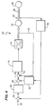
- FIG.5 illustrates yet another embodiment of the subject matter disclosed, in which a torsional mode damping control 70 is represented driven from a torque sensor 72 with signal conditioning to eliminate static torque and disturbance signals.
- the speed controller 12 provides drive commands to the machine drive 14 to turn on and off the electrical power to drive the electric machine 16 connected to the mechanical load 18 by the shaft 20.
- speed encoder pulses from the speed encoder 22 mounted to the mechanical shaft 20 are provided to the speed estimator device 24, the output of which is compared to the speed reference signal 26 at the first signal summation element 28 and fed to the speed controller 30 so that a reference current may be derived.
- torque control In conventional system with large voltage source converters, torque control is used in numerous applications. Usually the only feedback signals coming from the rotating shaft are speed and/or position signals and are derived from a shaft encoder. As noted before, in high power drive trains the resolution of shaft encoders is not sufficient to accurately measure torsional vibrations, due to the high stiffness of the rotor shaft assembly. Online torque measurements are the preferred feedback for a torque controller, but those of ordinary skill in the art know that such measurements are typically not used in drive trains because they are either not sufficiently accurate or expensive.
- the torque sensor 72 is a contactless sensor based on a magnetostrictive effect that enables torque measurements with high stability.
- Examples for such sensors are given in "Method and System for Non-contact Sensing of the Torque of a Shaft," European Patent Application No. 07113363.1-1242 (filed on July 7, 2007 , hereinafter the '363 patent, the contents of which are incorporated herein by reference in its entirety) and in "Torque Sensor", US Patent No. 7,243,557, issued on July 17, 2007 , hereinafter the '557 patent, the contents of which are incorporated herein by reference in its entirety.
- a signal conditioner 74 is used to improve the feedback torque signal supplied to a torque-damping controller 76. The signal conditioner is described in more detail in the '363 patent.
- torsional mode damping methods are normally based on feedback signals with typically one defined frequency
- the quality of the raw signal can easily be improved by the same signal conditioner 74, e. g. by a band-pass filter or more complex signal conditioning (e. g. in subtracting the signals from two of these sensors being 180° displaced along the shaft circumference, in order to eliminate disturbances with a frequency corresponding to the speed of the shaft).
- Most advantageous from a reliability point of view is the use of magnetically encoded shafts with multiple secondary sensors for measuring the magnetic field (see the '557 patent for examples). These secondary sensors are very low cost. Installing multiple redundant secondary sensors enables one to achieve the required level of reliability, even if single secondary sensors start to fail after a couple of years of operation.
- the output of the torque damping controller 76 is then added to the output of the speed controller 30 at a second summation element 78 to supply a modified current reference for the current controller 12.
- the current controller 12 will form drive command signals with a frequency content that will not excite and/or dampen the resonance modes of the mechanical shaft 20.
- measured current signals 32 are fed back and compared to the reference signal from the second summation element 78 at a third signal summation element 80 and fed to the current controller 12. As shown, feed forward information from the second summation element 78 is also supplied to the current controller 12.
- torsional mode damping feedback circuits are sensitive to dead times, e.g. being caused by simple signal conditioners, such as band-pass filters.
- a contactless torque sensor in combination with a suitable signal conditioner can be used to get a low cost, but high accuracy signal containing the amplitude and phase information of the most relevant mechanical torque harmonics.
- the signal from the torque sensor 72 described herein can be used to control torque disturbances for torsional issues caused by load commutated inverters as described in United States Patent No. 7,173,399 and United State Patent Application with Serial No. 11/381,900 (filed on May 5, 2006 ), both commonly assigned to the assignee of this application and incorporated herein by reference in their entirety.
- torsional mode damping controller 70 based on torque measurements with an economical torque sensor and a suitable signal conditioner interface with a voltage source converter would be simple to realize as a low cost and easy to install (retrofit) solution against torsional issues being caused by large voltage source converters.
- torsional vibrations correspond to frequencies below 100 Hz, or even lower, they can be damped in applying electrical damping torques to the rotating shaft (via the electrical motor driven by the voltage source converter).
- electrical damping torques For active damping, accurate information from the mechanical drive train is required (more accurate than what can be delivered by encoders in stiff shaft assemblies).
- a low cost (magnetostrictive torque sensor located at a relevant shaft position in combination with suitable signal conditioning can deliver this information. This seems better suited than other (especially indirect) sensing methods or estimators because torsional vibrations are caused by very small air-gap torque harmonics (e. g. 1 % effects). Trying to measure or to estimate them with sufficient accuracy may not be possible with existing sensors (e. g.
- the torque mode damping controller 70 of FIG. 5 can be utilized without having to change the existing power or drive system (e. g. as a retro-fit solution), can be applied at very low costs, requires low engineering effort (can be based on standard components), can be sufficiently reliable (e. g. in using redundant torque sensors), can be built and tested before knowing technical details of specific applications (same design for different VSC applications, can easily be tuned and tested on site), and can be applied and tested during a string test (requires only a small signal interface to the existing torque controller).
- the existing power or drive system e. g. as a retro-fit solution
- torque vibrations can also be controlled by superimposing a relatively small oscillating signal from a damping controller to the signal of an existing VSC torque controller, the amplitude of the oscillating signal being not higher than 1-2 % of the nominal torque.
- the frequencies of these small oscillating signals derived from one (or more) contactless torque measurement(s) and suitable signal conditioning, are chosen to correspond to (a) natural frequency (or frequencies) of the rotor shaft assembly.
- FIG. 6 illustrates an exemplary embodiment of an enhanced encoder algorithm according to an embodiment of the disclosed subject matter.
- equidistant vertical lines represent high resolution clock pulses 92 capable of measuring accurately the time between pulses 90, thus allowing the recovery of harmonic components from the measured pulses by use of a Field Programmable Gate Array, or FPGA, (200 MHz+) to measure the time between pulses.
- Pulses 90 represent a pulse sequence of an encoder rotating at a fixed speed.
- the disclosed enhanced algorithm is configured to count the number of samples within each "high” and "low” phase of the pulse.
- the output is a constant three units every three sample periods, as shown in the pulses 94, since the algorithm encounters three samples periods per transition from high to low or vice versa of the pulses.
- Curve 96 is the output of an encoder rotating at the same fundamental frequency as curve 90, but with a harmonic frequency superimposed.
- the output varies between two, three or four units, as shown by the bars 98 due to the changing number of sample periods encountered between transitions of the pulse sequence.
- the variations due to the harmonic frequency component of curve 96 are present in the output of the encoder.
Landscapes
- Engineering & Computer Science (AREA)
- Power Engineering (AREA)
- Control Of Electric Motors In General (AREA)
Priority Applications (1)
| Application Number | Priority Date | Filing Date | Title |
|---|---|---|---|
| EP07123819A EP2073375A1 (de) | 2007-12-20 | 2007-12-20 | Vorrichtung zur Vermeidung von Drehmomentkomponenten bei kritischen Frequenzen in Maschinenantriebssystemen |
Applications Claiming Priority (1)
| Application Number | Priority Date | Filing Date | Title |
|---|---|---|---|
| EP07123819A EP2073375A1 (de) | 2007-12-20 | 2007-12-20 | Vorrichtung zur Vermeidung von Drehmomentkomponenten bei kritischen Frequenzen in Maschinenantriebssystemen |
Publications (1)
| Publication Number | Publication Date |
|---|---|
| EP2073375A1 true EP2073375A1 (de) | 2009-06-24 |
Family
ID=39313020
Family Applications (1)
| Application Number | Title | Priority Date | Filing Date |
|---|---|---|---|
| EP07123819A Ceased EP2073375A1 (de) | 2007-12-20 | 2007-12-20 | Vorrichtung zur Vermeidung von Drehmomentkomponenten bei kritischen Frequenzen in Maschinenantriebssystemen |
Country Status (1)
| Country | Link |
|---|---|
| EP (1) | EP2073375A1 (de) |
Cited By (11)
| Publication number | Priority date | Publication date | Assignee | Title |
|---|---|---|---|---|
| CN102118036A (zh) * | 2009-12-31 | 2011-07-06 | 中国神华能源股份有限公司 | 利用抑制次同步振荡装置的动模试验方法 |
| ITCO20100013A1 (it) * | 2010-04-01 | 2011-10-02 | Nuovo Pignone Spa | Sistema e metodo di smorzamento del modo torsionale senza sensori |
| US8344673B2 (en) | 2008-12-04 | 2013-01-01 | Nuovo Pignone S.P.A. | Torsional mode damping apparatus |
| WO2013189609A3 (de) * | 2012-06-21 | 2014-06-05 | Brose Fahrzeugteile Gmbh & Co. Kg | Synchronmaschine und verfahren zum betrieb einer synchronmaschine |
| US8890454B2 (en) | 2010-04-01 | 2014-11-18 | Nuovo Pignone S.P.A. | Phase locked loop based torsional mode damping system and method |
| US8990031B2 (en) | 2009-12-10 | 2015-03-24 | Industrial Technology Research Institute | Torsional resonance frequency measuring device and method |
| US20150362388A1 (en) * | 2012-12-21 | 2015-12-17 | Continental Teves Ag & Co. Ohg | Method for detecting a torque applied to a shaft |
| EP3309955A1 (de) | 2016-10-11 | 2018-04-18 | Siemens Aktiengesellschaft | Betreiben eines umrichters zum koppeln einer für einen betrieb an wechselspannung ausgebildeten elektrischen maschine mit einem wechselspannungsnetz |
| US11251742B2 (en) | 2019-01-15 | 2022-02-15 | Abb Schweiz Ag | Damping torsional oscillations in a drive system |
| WO2022189373A1 (de) * | 2021-03-09 | 2022-09-15 | Robert Bosch Gmbh | Verfahren zur regelung eines motors, ein entsprechend geregelter motor und ein kompressorsystem mit einem derartigen motor |
| DE102022205454A1 (de) | 2022-05-31 | 2023-11-30 | Robert Bosch Gesellschaft mit beschränkter Haftung | Verfahren zu einem geräuscharmen Betrieb einer Elektromotorvorrichtung, eine Elektromotorvorrichtung und eine Kraftwärmemaschine |
Citations (5)
| Publication number | Priority date | Publication date | Assignee | Title |
|---|---|---|---|---|
| DE4132825A1 (de) | 1990-10-02 | 1992-04-16 | Toshiba Kawasaki Kk | Verfahren und vorrichtung zum regeln der drehzahl eines elektromotors |
| DE4427697A1 (de) | 1993-08-11 | 1995-02-16 | Fuji Electric Co Ltd | Steuervorrichtung für Motor mit variabler Drehzahl |
| US7173399B2 (en) | 2005-04-19 | 2007-02-06 | General Electric Company | Integrated torsional mode damping system and method |
| US7243557B2 (en) | 2003-12-30 | 2007-07-17 | Nctengineering Gmbh | Torque sensor |
| GB2437845A (en) | 2006-05-05 | 2007-11-07 | Gen Electric | Resistive Torsional Mode Damping System And Method |
-
2007
- 2007-12-20 EP EP07123819A patent/EP2073375A1/de not_active Ceased
Patent Citations (5)
| Publication number | Priority date | Publication date | Assignee | Title |
|---|---|---|---|---|
| DE4132825A1 (de) | 1990-10-02 | 1992-04-16 | Toshiba Kawasaki Kk | Verfahren und vorrichtung zum regeln der drehzahl eines elektromotors |
| DE4427697A1 (de) | 1993-08-11 | 1995-02-16 | Fuji Electric Co Ltd | Steuervorrichtung für Motor mit variabler Drehzahl |
| US7243557B2 (en) | 2003-12-30 | 2007-07-17 | Nctengineering Gmbh | Torque sensor |
| US7173399B2 (en) | 2005-04-19 | 2007-02-06 | General Electric Company | Integrated torsional mode damping system and method |
| GB2437845A (en) | 2006-05-05 | 2007-11-07 | Gen Electric | Resistive Torsional Mode Damping System And Method |
Cited By (21)
| Publication number | Priority date | Publication date | Assignee | Title |
|---|---|---|---|---|
| US8344673B2 (en) | 2008-12-04 | 2013-01-01 | Nuovo Pignone S.P.A. | Torsional mode damping apparatus |
| US8990031B2 (en) | 2009-12-10 | 2015-03-24 | Industrial Technology Research Institute | Torsional resonance frequency measuring device and method |
| CN102118036B (zh) * | 2009-12-31 | 2013-02-06 | 中国神华能源股份有限公司 | 利用抑制次同步振荡装置的动模试验方法 |
| CN102118036A (zh) * | 2009-12-31 | 2011-07-06 | 中国神华能源股份有限公司 | 利用抑制次同步振荡装置的动模试验方法 |
| AU2011234468B2 (en) * | 2010-04-01 | 2016-07-07 | Nuovo Pignone Tecnologie - S.R.L. | Sensorless torsional mode damping system and method |
| ITCO20100013A1 (it) * | 2010-04-01 | 2011-10-02 | Nuovo Pignone Spa | Sistema e metodo di smorzamento del modo torsionale senza sensori |
| WO2011121050A1 (en) * | 2010-04-01 | 2011-10-06 | Nuovo Pignone S.P.A. | Sensorless torsional mode damping system and method |
| CN102906991A (zh) * | 2010-04-01 | 2013-01-30 | 诺沃皮尼奥内有限公司 | 无传感器扭转模态阻尼系统和方法 |
| US8890454B2 (en) | 2010-04-01 | 2014-11-18 | Nuovo Pignone S.P.A. | Phase locked loop based torsional mode damping system and method |
| US9054629B2 (en) | 2010-04-01 | 2015-06-09 | Nuovo Pignone S.P.A. | Sensorless torsional mode damping system and method |
| CN102906991B (zh) * | 2010-04-01 | 2016-04-20 | 诺沃皮尼奥内有限公司 | 无传感器扭转模态阻尼系统和方法 |
| WO2013189609A3 (de) * | 2012-06-21 | 2014-06-05 | Brose Fahrzeugteile Gmbh & Co. Kg | Synchronmaschine und verfahren zum betrieb einer synchronmaschine |
| US20150362388A1 (en) * | 2012-12-21 | 2015-12-17 | Continental Teves Ag & Co. Ohg | Method for detecting a torque applied to a shaft |
| US9897498B2 (en) * | 2012-12-21 | 2018-02-20 | Continental Teves Ag & Co. Ohg | Method for detecting a torque applied to a shaft |
| EP3309955A1 (de) | 2016-10-11 | 2018-04-18 | Siemens Aktiengesellschaft | Betreiben eines umrichters zum koppeln einer für einen betrieb an wechselspannung ausgebildeten elektrischen maschine mit einem wechselspannungsnetz |
| WO2018068988A1 (de) | 2016-10-11 | 2018-04-19 | Siemens Aktiengesellschaft | Betreiben eines umrichters zum koppeln einer für einen betrieb an wechselspannung ausgebildeten elektrischen maschine mit einem wechselspannungsnetz |
| RU2717096C1 (ru) * | 2016-10-11 | 2020-03-18 | Сименс Акциенгезелльшафт | Эксплуатация вентильного преобразователя для соединения выполненной для работы на переменном напряжении электрической машины с сетью переменного напряжения |
| US10666177B2 (en) | 2016-10-11 | 2020-05-26 | Siemens Aktiengesellschaft | Operating an inverter for coupling an electric machine, designed for operation on AC voltage, with an AC voltage network |
| US11251742B2 (en) | 2019-01-15 | 2022-02-15 | Abb Schweiz Ag | Damping torsional oscillations in a drive system |
| WO2022189373A1 (de) * | 2021-03-09 | 2022-09-15 | Robert Bosch Gmbh | Verfahren zur regelung eines motors, ein entsprechend geregelter motor und ein kompressorsystem mit einem derartigen motor |
| DE102022205454A1 (de) | 2022-05-31 | 2023-11-30 | Robert Bosch Gesellschaft mit beschränkter Haftung | Verfahren zu einem geräuscharmen Betrieb einer Elektromotorvorrichtung, eine Elektromotorvorrichtung und eine Kraftwärmemaschine |
Similar Documents
| Publication | Publication Date | Title |
|---|---|---|
| EP2073375A1 (de) | Vorrichtung zur Vermeidung von Drehmomentkomponenten bei kritischen Frequenzen in Maschinenantriebssystemen | |
| EP2194290B1 (de) | System zum dämpfen von drehschwingungen | |
| EP3048333A1 (de) | Verfahren und system zur dämpfung von torsionsschwingungen | |
| US10100811B2 (en) | Noise control for a wind turbine | |
| EP2942867B1 (de) | Induktionsmotordrehzahlschätzung | |
| EP2073374B1 (de) | Vorrichtung zur Steuerung der Drehmomentoberschwingungen in PWM-Wandlern und dazugehörige Verfahren | |
| US9543852B2 (en) | Method and system for controlling a DC link voltage of a power converter connecting an electric generator of a wind turbine with a power grid | |
| Riemann et al. | Oil whip instability control using μ-synthesis technique on a magnetic actuator | |
| EP2216896B1 (de) | Drehmomentschwankungsüberwachung | |
| JP2013198221A (ja) | 電動機制御装置 | |
| AU2011234468B2 (en) | Sensorless torsional mode damping system and method | |
| KR101716250B1 (ko) | 구동 트레인의 시험 시스템 | |
| US20130200839A1 (en) | Rectifier based torsional mode damping system and method | |
| Balakrishnan et al. | Identification of resonance in hybrid stepper motor through measured current dynamics in online for accurate position estimation and control | |
| Oboe et al. | Use of MEMS inertial sensors for performance improvement of low-cost motion control systems | |
| Wieser et al. | The integration of machine fault detection into an indirect field oriented induction machine drive control scheme-the vienna monitoring method | |
| Bruha et al. | Torsional issues related to variable frequency control of elastic drive systems | |
| JP4668776B2 (ja) | モータのトルクリプル測定方法、測定装置、トルクリプル抑制方法およびその抑制方法を適用したモータ駆動装置 | |
| Sihler et al. | Torsional Mode Damping For Electrically Driven Gas Compression Trains In Extended Variable Speed Operation. | |
| Klaus et al. | A new dynamic torque calibration device at PTB | |
| Arva et al. | Analysis on vibration and resonance characteristics of an low speed 3-phase stepper motor | |
| EP4250035A1 (de) | System und verfahren zur maschinendiagnose | |
| EP4250027A1 (de) | System und verfahren zur maschinendiagnose | |
| Klaus et al. | The 20 N⋅ m dynamic torque calibration device at PTB | |
| Dutka et al. | Analysis and remedies for torsional oscillations in rotating machinery |
Legal Events
| Date | Code | Title | Description |
|---|---|---|---|
| PUAI | Public reference made under article 153(3) epc to a published international application that has entered the european phase |
Free format text: ORIGINAL CODE: 0009012 |
|
| AK | Designated contracting states |
Kind code of ref document: A1 Designated state(s): AT BE BG CH CY CZ DE DK EE ES FI FR GB GR HU IE IS IT LI LT LU LV MC MT NL PL PT RO SE SI SK TR |
|
| AX | Request for extension of the european patent |
Extension state: AL BA HR MK RS |
|
| 17P | Request for examination filed |
Effective date: 20091228 |
|
| 17Q | First examination report despatched |
Effective date: 20100125 |
|
| AKX | Designation fees paid |
Designated state(s): AT BE BG CH CY CZ DE DK EE ES FI FR GB GR HU IE IS IT LI LT LU LV MC MT NL PL PT RO SE SI SK TR |
|
| APBK | Appeal reference recorded |
Free format text: ORIGINAL CODE: EPIDOSNREFNE |
|
| APBN | Date of receipt of notice of appeal recorded |
Free format text: ORIGINAL CODE: EPIDOSNNOA2E |
|
| APBR | Date of receipt of statement of grounds of appeal recorded |
Free format text: ORIGINAL CODE: EPIDOSNNOA3E |
|
| APAF | Appeal reference modified |
Free format text: ORIGINAL CODE: EPIDOSCREFNE |
|
| APBT | Appeal procedure closed |
Free format text: ORIGINAL CODE: EPIDOSNNOA9E |
|
| STAA | Information on the status of an ep patent application or granted ep patent |
Free format text: STATUS: THE APPLICATION HAS BEEN REFUSED |
|
| 18R | Application refused |
Effective date: 20181206 |
|
| P01 | Opt-out of the competence of the unified patent court (upc) registered |
Effective date: 20230526 |