EP2073347A2 - Electric motor - Google Patents
Electric motor Download PDFInfo
- Publication number
- EP2073347A2 EP2073347A2 EP08022027A EP08022027A EP2073347A2 EP 2073347 A2 EP2073347 A2 EP 2073347A2 EP 08022027 A EP08022027 A EP 08022027A EP 08022027 A EP08022027 A EP 08022027A EP 2073347 A2 EP2073347 A2 EP 2073347A2
- Authority
- EP
- European Patent Office
- Prior art keywords
- electric motor
- return body
- media line
- motor according
- media
- Prior art date
- Legal status (The legal status is an assumption and is not a legal conclusion. Google has not performed a legal analysis and makes no representation as to the accuracy of the status listed.)
- Withdrawn
Links
Images


Classifications
-
- H—ELECTRICITY
- H02—GENERATION; CONVERSION OR DISTRIBUTION OF ELECTRIC POWER
- H02K—DYNAMO-ELECTRIC MACHINES
- H02K7/00—Arrangements for handling mechanical energy structurally associated with dynamo-electric machines, e.g. structural association with mechanical driving motors or auxiliary dynamo-electric machines
- H02K7/14—Structural association with mechanical loads, e.g. with hand-held machine tools or fans
- H02K7/145—Hand-held machine tool
-
- H—ELECTRICITY
- H02—GENERATION; CONVERSION OR DISTRIBUTION OF ELECTRIC POWER
- H02K—DYNAMO-ELECTRIC MACHINES
- H02K1/00—Details of the magnetic circuit
- H02K1/06—Details of the magnetic circuit characterised by the shape, form or construction
- H02K1/12—Stationary parts of the magnetic circuit
- H02K1/20—Stationary parts of the magnetic circuit with channels or ducts for flow of cooling medium
-
- H—ELECTRICITY
- H02—GENERATION; CONVERSION OR DISTRIBUTION OF ELECTRIC POWER
- H02K—DYNAMO-ELECTRIC MACHINES
- H02K11/00—Structural association of dynamo-electric machines with electric components or with devices for shielding, monitoring or protection
- H02K11/0094—Structural association with other electrical or electronic devices
-
- H—ELECTRICITY
- H02—GENERATION; CONVERSION OR DISTRIBUTION OF ELECTRIC POWER
- H02K—DYNAMO-ELECTRIC MACHINES
- H02K3/00—Details of windings
- H02K3/46—Fastening of windings on the stator or rotor structure
- H02K3/47—Air-gap windings, i.e. iron-free windings
-
- A—HUMAN NECESSITIES
- A61—MEDICAL OR VETERINARY SCIENCE; HYGIENE
- A61C—DENTISTRY; APPARATUS OR METHODS FOR ORAL OR DENTAL HYGIENE
- A61C1/00—Dental machines for boring or cutting ; General features of dental machines or apparatus, e.g. hand-piece design
- A61C1/02—Dental machines for boring or cutting ; General features of dental machines or apparatus, e.g. hand-piece design characterised by the drive of the dental tools
- A61C1/06—Dental machines for boring or cutting ; General features of dental machines or apparatus, e.g. hand-piece design characterised by the drive of the dental tools with electric drive
-
- H—ELECTRICITY
- H02—GENERATION; CONVERSION OR DISTRIBUTION OF ELECTRIC POWER
- H02K—DYNAMO-ELECTRIC MACHINES
- H02K5/00—Casings; Enclosures; Supports
- H02K5/04—Casings or enclosures characterised by the shape, form or construction thereof
- H02K5/22—Auxiliary parts of casings not covered by groups H02K5/06-H02K5/20, e.g. shaped to form connection boxes or terminal boxes
- H02K5/225—Terminal boxes or connection arrangements
Definitions
- the invention relates to an electric motor, comprising a rotatably mounted rotor on a rotor shaft and a stator surrounding the rotor, wherein the stator has a return body and a current acted upon winding and the electric motor has at least one media line.
- Generic electric motors are used for example for the drive of rotating, dental or medical instruments.
- the rotating instruments such as drills or the like are attached via a standard coupling to the electric motor.
- the dental instrument is to be supplied during use with different supply media via one or more media lines.
- the media lines have a certain diameter and are to be integrated in the engine area, with known dental instruments such as handheld devices should not exceed certain external dimensions, so as not to affect the usability and manageability.
- the electric motor has to provide sufficient torque and speed.
- the invention is based on an electric motor as described above and proposes that the return body receives at least one passage for the at least partial formation or recording of the media line or media lines for performing one or more media.
- the return body which anyway is present due to the functioning of the electric motor, is now additionally used to receive the media line (s) for the passage of the media through the engine.
- This integration of the media lines / s in the return body is for the arrangement of the media line / s no additional space required, the influences of the media line / s on the magnetic properties are also negligible in clever arrangement of the media / en s, which leads to almost unchanged characteristics of the electric motor according to the invention.
- this also means that the space obtained by the integration of the media line in the return body can be added to the stator or the winding on the stator and so the electric motor according to the invention with a constant outside dimensions of the article according to the invention in comparison with the object of the prior art Improvement of its characteristics learns.
- the invention comprises, as already mentioned, both an embodiment in which the implementation in the return body receives one or more media lines, as well as the variant in which the implementation forms the media line.
- the implementation in the return body is preferably provided as a hose-like channel, as a tunnel or as a bore for forming or receiving the media line / s.
- the invention proposes that the media line (s) support and / or operate the elements driven by the electric motor, such as e.g. of tools or a spindle.
- the electric motor such as e.g. of tools or a spindle.
- This now makes it possible, space-saving, for example, when used as a dental motor, to provide the tools required for the tool media, such as cooling air, rinse water, which is under high pressure, while making the drive of the tool.
- the embodiment according to the invention therefore offers the possibility of offering a very space-saving solution which is far superior in terms of ease of use to the solutions known in the prior art.
- the known from the prior art solutions that deal exclusively with the cooling of the electric motor or its stator or rotor are not suitable for the purpose as described above.
- the invention provides a very elegant solution which elegantly solves all problems known in the art.
- an embodiment of the invention is characterized in that the media lines are guided by the side facing away from the drive side of the electric motor to the drive side facing by the electric motor.
- the media lines are guided by the side facing away from the drive side of the electric motor to the drive side facing by the electric motor.
- the variant described first is preferred.
- the invention is also characterized by the fact that the media lines are provided as units spatially separated from the engine. This makes it possible to feed one or more media through the engine, without burdening it or without significantly reducing its performance. This has already been described earlier.
- the media line in the electric motor is relatively far outside. This is advantageous since it is then possible to dispense with bends or offsets of the media line (s) in the further course since the media line (s), for example gas, air, water and so on are often used or available at a certain distance from the processing point to deliver. On the one hand, this facilitates the manufacture of the electric motor according to the invention or of the dental tool or instrument driven therewith and, on the other hand, also improves the flow properties.
- the media guide in the stator return plate allows a small air gap between rotor and stator and thus a high magnetic flux in the magnetic circuit.
- a hose-like channel, a tunnel or a bore for forming or receiving the media line is provided in the return body.
- the return body is constructed, for example, sleeve-like and has a bore which forms the media line. But a same type of media line is also formed when the return body is formed of a plurality of identically formed backwash discs, which have an opening or an opening at a predetermined position. If these discs are stacked on top of each other, the respective openings come to lie in the same position and thus also form a channel, more precisely a tube-like channel or tunnel, as in the case of a bore.
- a hose-like, all-sided closed channel as a media line and deliberately in the return body to form a groove or throat as a media line.
- an outer sleeve slipped over or inserted an inner tube, so as to obtain a sealed media line.
- the term "media line" is to be interpreted very broadly according to the invention.
- the invention provides that the introduced into the return body bore or hose-like channel or tunnel itself forms the media line, so for example as a pipe, and thus serves as part of the pipe system for gases or water or other liquids and so on.
- the hose-like channel, tunnel or bore can also be used to accommodate another media line, for example a power cable, data line (for example from sensors) or a fiber-optic cable. The chosen wording covers both cases.
- the electric motors according to the invention are of course also equipped with mixed shaping of the design of the media line alternatively.
- the invention comprises both electric motors, the only with a media line, as well Electric motors equipped with several media lines. Even if above and below often only spoken by a media line, so these statements are of course also in the same way to the arrangements with multiple media lines.
- the media line is arranged obliquely in the return body, with respect to the axis of rotation of the rotary shaft.
- Such an orientation as well as a likewise alternatively provided arrangement of the media line in the return body on a spiral or helical path leads to improve the magnetic behavior of the return body or of the entire electric motor.
- the incorporation of the media line as material weakening or by material removal in the magnetic return body leads to a corresponding impairment of the magnetic properties.
- Cogging moments are formed on the electric motor due to the different magnetic properties of the return body. But now that the arrangement of the magnetic properties affecting media line changed in the axial direction, the negative effect of the cogging moments is mitigated or no longer appears.
- the media line is laid in the return body along a direction which deviates from the parallels to the axis of rotation of the rotor shaft.
- this may be an arrangement running obliquely thereto or, on the other hand, a helical or helical path, which then, for example, passes through the return body in a helical manner.
- a helical path differs from a helical path by the changing diameter of the helical path with respect to the constant diameter of the helical path.
- a cogging moment is well suppressive variants but of course also an electric motor, in which the media line / s is arranged parallel to the axis of rotation of the rotor shaft, according to the invention. If, for example, the electric motor is only penetrated by one or a few media lines, no disturbing cogging torques may form during operation.
- the return body has a certain wall thickness and is often formed like a cylinder or sleeve.
- the media line is arranged centrally and surrounded on all sides by the material of the return body.
- the media line is arranged in the edge region of the return body on the inside or outside.
- the invention nevertheless includes solutions in which a bore or a tubular media line is provided in the edge region or a nut or throat-like configuration is selected. This depends on the resulting desired magnetic properties on the one hand, but also on the purpose of the media line on the other hand. For example, the insertion of an optical fiber as a means of illumination or the insertion of an electrical cable into a groove or throat is easier than passing through a hole or tunnel several centimeters long. Accordingly, the assembly is facilitated.
- a bore or a hose-like design of the media line from the outset a dense arrangement, which is desired for example for the conduction of gases or liquids.
- the return body is designed as a sleeve.
- This sleeve is integrally formed, for example, as a rotating part and has, for example, an axially extending bore or, on the surface (inner or outer surface) coiled or inclined, a groove.
- the return body in addition to the one-piece design of the return body as a sleeve, it is also provided in a further development according to the invention, which consists of the return body of several combined sleeve segments.
- the sleeve segments are optionally identical or different again.
- the sleeve segments touch each other at their respective end faces and are suitably connectable to each other.
- the arrangement of sleeve segments has advantages in particular for the incorporation of the media lines, since these can be realized, for example, at the end faces, for example by milling out the end face.
- the return body consists of a multiplicity of rear disks arranged side by side in the axial direction.
- a multiplicity of essentially identically shaped backwash disks are put together in a packet-like manner and, at their respective circumferential position, have corresponding breaks or perforations or openings in a predefined manner in order to bring about or receive the media line (s). There are thus formed corresponding grooves or tunnels over the entire length of the return body.
- the electric motor according to the invention is preferably designed as a DC motor, in particular for the application of a drive for dental instruments, the electric motor according to the invention is designed as a brushless DC motor.
- the media line / s for the transport of gases such as air, compressed air, cooling air, cleaning gases, liquids, water, liquid gas mixtures, spray water, cooling water, electricity or light is used.
- gases such as air, compressed air, cooling air, cleaning gases, liquids, water, liquid gas mixtures, spray water, cooling water, electricity or light.
- the media line (groove, tunnel and so on) receives these optical fibers.
- the invention not only includes an electric motor as described above, but also relates to a medical or dental tool which is driven by such an electric motor. It should be noted that this application is only one of many cases in which the electric motor according to the invention can be used. In this respect, the design of the electric motor is not bound to certain size specifications.
- the electric motor can also be used in machines that are significantly larger than a hand-held medical or dental tool.
- the invention also includes tool motor spindles, in which an electric motor as described is used as a direct drive and z. B. Coolant is passed to the processing tool.
- Medical or dental tools often have a coupling to which various medical or dental instruments or devices can be coupled. As a result, the application of such a tool is considerably increased. Often, such tools require the use of appropriate media which are to be brought in via media lines.
- Fig. 1 a part of the electric motor according to the invention is shown in a three-dimensional view. Not shown are the moving, because rotating parts of the electric motor.
- the drive parts of the electric motor are arranged in a motor housing, wherein with the housing, a coupling piece is connected, on which a to be driven by the electric motor dental or medical Instrument or device can be plugged.
- the coupler is often a standard coupling to achieve interchangeability with other systems.
- the electric motor 1 has a rotor shaft mounted in the motor or motor housing, for this purpose corresponding motor bearings are provided in a known manner.
- the rotor (not shown) is surrounded by the stator 2.
- the stator 2 consists of a return body 3 and a current acted upon winding 4.
- the rotor has a permanent magnet which begins to rotate due to the magnetic field building up in the winding 4.
- the permanent magnet of the rotor is designed as a bipolar, diametrically oriented rotor magnet.
- the return body 3, which often consists of soft magnetic material, serves to effectively guide the magnetic field generated by the current-applied winding 4.
- the winding 4 is provided on the inner side 33 of the return body 3.
- a protective layer or protective sleeve 40 is provided, which is arranged between the winding 4 and the rotor (not shown).
- This e.g. formed as a protective sheath protective sleeve 40 may be, for example, an encapsulation of the winding 4.
- media lines 5 project parallel to the longitudinal extent of the electric motor 1. These media lines 5 serve, for example, to conduct gases, air, water, liquids, electricity, light and so on.
- the return body 3, the media lines 5 receives.
- a (not shown) axis of rotation of the rotor shaft extending bore or passage formed as a tunnel 30 is provided in which / m, the media line 5 extends.
- media management is to be understood very comprehensively.
- a media line is understood to be a separate, closed system for conducting the medium, as provided for example in an electrical cable, which has a correspondingly insulating sheath.
- the term “media line” 5 can also be designed so that the trained as a tunnel bushing 30 or the bore or the channel or the grooves 31, 32 themselves are part of the media line 5, especially if this part of a pipe system for water , Liquids, gas and so on.
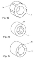
- Fig. 2a an alternative embodiment of the return body 3 is shown. It consists here of provided on the outside of the sleeve-like yoke body 3 grooves 31st
- Fig. 2b the media line 5 is provided in grooves 32 provided on the inside. It is clear that a multiplicity of media lines can be laid here, since a multiplicity of grooves are also arranged.
- FIG. 2c shown embodiment of the return body. 3 corresponds to the in Fig. 1 built-in return body 3.
- the inference body 3 shown in the embodiments are sleeve-like or cylinder-like, without wishing to limit the invention in any way. They may be made in one piece or consist of different sleeve segments or consist of a variety of assembled to a package backwash discs, which are similar or identical among themselves.
- the design of the return body 3 is not bound to a cylindrical configuration, in particular the outer contour of the return body can be formed oval or rectangular.
- a sleeve-like casing 10 is provided, which either has a protective function for the electric motor or may also be part of the motor housing.
Abstract
Description
Die Erfindung betrifft einen Elektromotor, bestehend aus einem auf einer Rotorwelle drehbar gelagerten Rotor und einen den Rotor umgebenden Stator, wobei der Stator einen Rückschlusskörper und eine mit Strom beaufschlagbare Wicklung aufweist und der Elektromotor mindestens eine Medienleitung besitzt.The invention relates to an electric motor, comprising a rotatably mounted rotor on a rotor shaft and a stator surrounding the rotor, wherein the stator has a return body and a current acted upon winding and the electric motor has at least one media line.
Gattungsgemäße Elektromotoren werden zum Beispiel für den Antrieb von rotierenden, dentalen oder medizinischen Instrumenten eingesetzt. Zu diesem Zweck werden die rotierenden Instrumente, zum Beispiel Bohrer oder ähnliches über eine genormte Kupplung auf den Elektromotor aufgesteckt. Das dentale Instrument ist während des Einsatzes mit verschiedenen Versorgungsmedien über eine oder mehrere Medienleitungen zu versorgen. Es wird zum Beispiel im dentalen Anwendungsbereich Sprayluft, Spraywasser, Kühlluft, Strom, Licht und so weiter benötigt, die über den Elektromotor zu den angetriebenen dentalen Instrumenten, in den Werkzeugkopf zugeführt werden muss. Die Medienleitungen haben natürlich einen gewissen Durchmesser und sind im Motorbereich zu integrieren, wobei bekanntermaßen entsprechende Dentalinstrumente als Handgeräte gewisse Außenmaße nicht überschreiten sollten, um die Bedienbarkeit und Handlichkeit nicht zu beeinträchtigen. Gleichzeitig hat der Elektromotor aber ein ausreichendes Drehmoment und Drehzahl zur Verfügung zu stellen.Generic electric motors are used for example for the drive of rotating, dental or medical instruments. For this purpose, the rotating instruments, such as drills or the like are attached via a standard coupling to the electric motor. The dental instrument is to be supplied during use with different supply media via one or more media lines. For example, in the dental application field of spray air, spray water, cooling air, electricity, light and so on, it is necessary to use the Electric motor to the driven dental instruments, must be fed into the tool head. Of course, the media lines have a certain diameter and are to be integrated in the engine area, with known dental instruments such as handheld devices should not exceed certain external dimensions, so as not to affect the usability and manageability. At the same time, however, the electric motor has to provide sufficient torque and speed.
Im Stand der Technik sind mehrere Lösungen bekannt, die eine Durchführung einer Medienleitung durch den Rückschlußkörper eines Motors zeigen. Allen Lösungen des Standes der Technik, die bekannt geworden sind, umfassen dabei Lösungen, die sich ausschließlich mit der Kühlung des Motors bzw. des Rückschlußkörpers beschäftigen.In the prior art, several solutions are known which show a passage of a media line through the return body of an engine. All solutions of the prior art that have become known include solutions that deal exclusively with the cooling of the motor or the return path body.
Ausgehend von diesem Stand der Technik ist es Aufgabe der vorliegenden Erfindung einen Elektromotor zur Verfügung zu stellen, der eine geschickte Durchführung der Medienleitung/en durch den Elektromotor zu finden, wobei die Eigenschaften des Elektromotors nicht merklich beeinträchtigt sind.Based on this prior art, it is an object of the present invention to provide an electric motor to find a clever implementation of the media line / s by the electric motor, wherein the properties of the electric motor are not appreciably affected.
Zur Lösung dieser Aufgabe geht die Erfindung aus von einem Elektromotor wie eingangs beschrieben und schlägt vor, dass der Rückschlusskörper zumindest eine Durchführung für die wenigstens teilweise Bildung oder Aufnahme der Medienleitung beziehungsweise Medienleitungen zur Durchführung eines oder mehrerer Medien aufnimmt. Je nach Anwendungsfall des erfindungsgemäßen Elektromotors ist eine oder aber auch mehrer Medienleitungen durch den Elektromotor zu führen. Der aufgrund der Funktionsweise des Elektromotors sowieso vorhandene Rückschlusskörper wird jetzt zusätzlich dazu verwendet, die Medienleitung/en zur Durchführung der Medien durch den Motor aufzunehmen. Durch diese Integration der Medienleitungen/en in den Rückschlusskörper, wird für die Anordnung der Medienleitung/en kein zusätzliche Bauraum benötigt, die Einflüsse der Medienleitung/en auf die magnetischen Eigenschaften sind bei geschickter Anordnung der Medienleitung/en auch vernachlässigbar, was zu fast unveränderten Kennzahlen des erfindungsgemäßen Elektromotors führt. Umgekehrt bedeutet dies aber auch, dass der durch die Integration der Medienleitung in den Rückschlusskörper gewonnene Bauraum dem Stator beziehungsweise der Wicklung am Stator zugegeben werden kann und so der erfindungsgemäße Elektromotor bei gleichbleibenden Außenabmessungen des erfindungsgemäßen Gegenstandes im Vergleich mit dem Gegenstand nach dem Stand der Technik eine Verbesserung seiner Kenndaten erfährt.To achieve this object, the invention is based on an electric motor as described above and proposes that the return body receives at least one passage for the at least partial formation or recording of the media line or media lines for performing one or more media. Depending on the application of the electric motor according to the invention one or more media lines is to be guided by the electric motor. The return body, which anyway is present due to the functioning of the electric motor, is now additionally used to receive the media line (s) for the passage of the media through the engine. This integration of the media lines / s in the return body, is for the arrangement of the media line / s no additional space required, the influences of the media line / s on the magnetic properties are also negligible in clever arrangement of the media / en s, which leads to almost unchanged characteristics of the electric motor according to the invention. Conversely, this also means that the space obtained by the integration of the media line in the return body can be added to the stator or the winding on the stator and so the electric motor according to the invention with a constant outside dimensions of the article according to the invention in comparison with the object of the prior art Improvement of its characteristics learns.
Im Gegensatz zu allen, im Stand der Technik bekannten Lösungen ist es bei der vorliegenden erfindungsgemäßen Lösung nicht vorgesehen, die Medien, die durch den Rückschlußkörper geführt werden, am Motor selbst, beispielsweise zur Kühlung zu verwenden, sondern es handelt sich tatsächlich um eine Lösung, bei der es gelingt, Medienleitungen, die beispielsweise an einem von dem Motor angetriebenen Werkzeug benötigt werden, durch den Motor ohne bzw. mit minimalem Leistungsverlust für den Motor durch diesen hindurch zu führen. Dabei ist es sowohl möglich, die Medienleitung oder die Medienleitungen von der einen Seite an einen Motor anzukoppeln, nämlich an die Durchführung durch den Motor, die Medienleitung selbst wird dann durch den im Motor vorhandenen Kanal beispielsweise gebildet. Auf der anderen Seite kann dann wieder eine Medienleitung angekoppelt bzw. angeschlossen werden.In contrast to all known in the prior art solutions, it is not provided in the present inventive solution to use the media that are passed through the return body, on the engine itself, for example, for cooling, but it is actually a solution in which it is possible to pass through the motor, the power lines, which are required for example on a motor-driven tool, through the motor with no or minimal power loss for the motor through the motor. It is both possible to couple the media line or the media lines from one side to a motor, namely to the passage through the engine, the media line itself is then formed by the existing channel in the engine, for example. On the other side, a media line can then be connected or connected again.
Geschickterweise geschieht dies so, daß die Durchführung von der dem Antrieb abgewanden Seite bzw. von der dem anzutreibenden Werkzeug bzw. von der angetriebenen Spindel abgewandten Seite auf die dem Werkzeug zugewandte Seite zu führen. Die Medien, egal ob gasförmig oder flüssig oder aber letztlich elektrische Leitungen oder dergleichen, dienen dabei nicht der Verwendung in bzw. an dem Motor selbst, sondern gehen sozusagen an dem Motor vorbei.Cleverly, this is done so that the implementation of the side facing away from the drive or of the tool to be driven or the driven spindle side facing away from the tool facing side. The media, whether gaseous or liquid or ultimately electrical lines or the like, are used not the use in or on the engine itself, but go so to speak on the engine over.
Man kann also von räumlich getrennten Einheiten sprechen, die durch die erfindungsgemäße Lösung zur Verfügung gestellt werden.One can therefore speak of spatially separated units, which are provided by the inventive solution.
Die Erfindung umfasst dabei, wie bereits erwähnt, sowohl eine Ausgestaltung, bei der die Durchführung im Rückschlußkörper eine oder mehrere Medienleitungen aufnimmt, genauso wie die Variante, bei der die Durchführung die Medienleitung bildet. Die Durchführung im Rückschlußkörper ist dabei bevorzugt als schlauchartiger Kanal, als Tunnel oder als Bohrung zur Bildung oder Aufnahme der Medienleitung/en vorgesehen.The invention comprises, as already mentioned, both an embodiment in which the implementation in the return body receives one or more media lines, as well as the variant in which the implementation forms the media line. The implementation in the return body is preferably provided as a hose-like channel, as a tunnel or as a bore for forming or receiving the media line / s.
Des weiteren schlägt die Erfindung vor, daß die Medienleitung/en Unterstützung und/oder zum Betreiben der von dem Elektromotor angetriebenen Elemente, wie z.B. von Werkzeugen oder einer Spindel dient. Dadurch gelingt es jetzt, platzsparend, beispielsweise beim Einsatz als Dentalmotor, die am Werkzeug benötigten Medien, wie Kühlluft, Spülwasser, welches unter hohem Druck steht, zur Verfügung zu stellen und gleichzeitig den Antrieb des Werkzeuges vorzunehmen. Die Ausgestaltung nach der Erfindung bietet daher die Möglichkeit, eine sehr platzsparende Lösung anzubieten, die insbesondere vom Bedienkomfort den im Stand der Technik bekannten Lösungen weit überlegen ist. Die aus dem Stand der Technik bekannten Lösungen, die sich ausschließlich mit der Kühlung des Elektromotors bzw. seines Stators oder Rotors beschäftigen, sind für den Einsatzzweck, wie er zuvor beschrieben wurde, nicht geeignet.Furthermore, the invention proposes that the media line (s) support and / or operate the elements driven by the electric motor, such as e.g. of tools or a spindle. This now makes it possible, space-saving, for example, when used as a dental motor, to provide the tools required for the tool media, such as cooling air, rinse water, which is under high pressure, while making the drive of the tool. The embodiment according to the invention therefore offers the possibility of offering a very space-saving solution which is far superior in terms of ease of use to the solutions known in the prior art. The known from the prior art solutions that deal exclusively with the cooling of the electric motor or its stator or rotor are not suitable for the purpose as described above.
Die Erfindung stellt demgegenüber eine sehr elegante Lösung zur Verfügung, die alle im Stand der Technik bekannten Probleme elegant löst.In contrast, the invention provides a very elegant solution which elegantly solves all problems known in the art.
Wie bereits erwähnt, zeichnet sich eine Ausgestaltung der Erfindung dadurch aus, daß die Medienleitungen von der der Antriebsseite abgewandten Seite des Elektromotors zu der dem Antrieb zugewandten Seite durch den Elektromotor geführt werden. Selbstverständlich ist es, falls erforderlich, auch möglich, die umgekehrte Richtung zu wählen. Bevorzugt ist allerdings die zuerstbeschriebene Variante.As already mentioned, an embodiment of the invention is characterized in that the media lines are guided by the side facing away from the drive side of the electric motor to the drive side facing by the electric motor. Of course, if necessary, it is also possible to choose the reverse direction. However, the variant described first is preferred.
Die Erfindung zeichnet sich auch dadurch aus, daß die Medienleitungen als vom Motor räumlich getrennte Einheiten vorgesehen sind. Dadurch gelingt es, ein oder mehrere Medien durch den Motor hindurch zuführen, ohne diesen zu belasten bzw. ohne dessen Leistungskraft wesentlich zu verringern. Dies wurde weiter vorne bereits beschrieben.The invention is also characterized by the fact that the media lines are provided as units spatially separated from the engine. This makes it possible to feed one or more media through the engine, without burdening it or without significantly reducing its performance. This has already been described earlier.
Durch den erfindungsgemäßen Vorschlag wird die Medienleitung im Elektromotor verhältnismäßig weit außen angeordnet. Dies ist vorteilhaft, da dann auf Abwinkelungen oder Abkröpfungen der Medienleitung/en im weiteren Verlauf verzichtet werden kann, da oftmals angestrebt ist die Medienleitung/en, zum Beispiel Gas, Luft, Wasser und so weiter in einem gewissen Abstand zum Bearbeitungspunkt einzusetzen beziehungsweise zur Verfügung zu stellen. Zum einen wird dadurch die Herstellung des erfindungsgemäßen Elektromotors beziehungsweise des damit angetriebenen Dentalwerkzeuges beziehungsweise Instrumentes erleichtert und zum anderen auch die Strömungseigenschaften verbessert.The inventive proposal, the media line in the electric motor is relatively far outside. This is advantageous since it is then possible to dispense with bends or offsets of the media line (s) in the further course since the media line (s), for example gas, air, water and so on are often used or available at a certain distance from the processing point to deliver. On the one hand, this facilitates the manufacture of the electric motor according to the invention or of the dental tool or instrument driven therewith and, on the other hand, also improves the flow properties.
Des Weiteren ermöglicht die Medienführung im Stator-Rückschlussblech einen kleinen Luftspalt zwischen Rotor und Stator und somit einen hohen magnetischen Fluss im Magnetkreis.Furthermore, the media guide in the stator return plate allows a small air gap between rotor and stator and thus a high magnetic flux in the magnetic circuit.
In einer bevorzugten Variante der Erfindung ist vorgesehen, dass im Rückschlusskörper ein schlauchartiger Kanal, ein Tunnel oder eine Bohrung zur Bildung oder Aufnahme der Medienleitung vorgesehen ist.In a preferred variant of the invention it is provided that a hose-like channel, a tunnel or a bore for forming or receiving the media line is provided in the return body.
Für die Ausgestaltung des Rückschlusskörpers gibt es eine Vielzahl von Realisierungsmöglichkeiten, wie noch weiter später erläutert wird. Grundsätzlich ist es möglich, dass der Rückschlusskörper zum Beispiel hülsenartig aufgebaut ist und eine Bohrung aufweist, welche die Medienleitung bildet. Eine gleiche Art von Medienleitung entsteht aber auch, wenn der Rückschlusskörper aus einer Vielzahl von gleichartig ausgebildeten Rückschlussscheiben gebildet ist, die an vorgegebener Position eine Öffnung oder einen Durchbruch besitzen. Stapelt man nun diese Scheiben übereinander, so kommen die jeweiligen Öffnungen an der gleichen Position zu liegen und bilden auch so einen Kanal, genaugenommen einen schlauchartigen Kanal oder Tunnel, wie bei einer Bohrung. Natürlich ist es auch möglich, an Stelle eines schlauchartigen, allseitig geschlossenen Kanals als Medienleitung auch bewusst im Rückschlusskörper eine Nut oder Kehle als Medienleitung auszubilden. Gegebenenfalls wird dann, je nachdem, wo diese Nut oder Kehle an dem Rückschlusskörper angeordnet ist, eine Außenhülse übergestülpt oder ein Innenrohr eingesteckt, um so eine abgeschlossene Medienleitung zu erhalten. Der Begriff "Medienleitung" ist erfindungsgemäß sehr weit auszulegen. Zunächst ist erfindungsgemäß vorgesehen, dass die in den Rückschlusskörper eingebrachte Bohrung oder der schlauchartige Kanal beziehungsweise Tunnel selber die Medienleitung bildet, also zum Beispiel als Rohr, und somit als Teil des Leitungssystemes für Gase oder Wasser oder andere Flüssigkeiten und so weiter dient. Der schlauchartige Kanal, Tunnel oder die Bohrung kann aber in einer anderen Variante auch der Aufnahme einer anderen Medienleitung, zum Beispiel einem Stromkabel, Datenleitung (zum Beispiel von Sensoren) oder einem Glasfaserkabel, dienen. Die gewählte Formulierung deckt beide Fälle ab.For the embodiment of the magnetic return body, there are a variety of implementation options, as will be explained later. In principle, it is possible that the return body is constructed, for example, sleeve-like and has a bore which forms the media line. But a same type of media line is also formed when the return body is formed of a plurality of identically formed backwash discs, which have an opening or an opening at a predetermined position. If these discs are stacked on top of each other, the respective openings come to lie in the same position and thus also form a channel, more precisely a tube-like channel or tunnel, as in the case of a bore. Of course, it is also possible, instead of a hose-like, all-sided closed channel as a media line and deliberately in the return body to form a groove or throat as a media line. Optionally, then, depending on where this groove or throat is disposed on the return body, an outer sleeve slipped over or inserted an inner tube, so as to obtain a sealed media line. The term "media line" is to be interpreted very broadly according to the invention. First, the invention provides that the introduced into the return body bore or hose-like channel or tunnel itself forms the media line, so for example as a pipe, and thus serves as part of the pipe system for gases or water or other liquids and so on. However, in another variant, the hose-like channel, tunnel or bore can also be used to accommodate another media line, for example a power cable, data line (for example from sensors) or a fiber-optic cable. The chosen wording covers both cases.
Es ist klar, dass die erfindungsgemäßen Elektromotoren natürlich auch mit Mischformung der Ausgestaltung der Medienleitung alternativ ausgestattet sind. Dabei umfasst die Erfindung sowohl Elektromotoren, die nur mit einer Medienleitung, wie auch Elektromotoren, die mit mehreren Medienleitungen ausgestattet sind. Auch wenn vorstehend und nachfolgend oftmals nur von einer Medienleitung gesprochen wird, so beziehen sich diese Aussagen natürlich auch in gleicher Weise auch auf die Anordnungen mit mehreren Medienleitungen.It is clear that the electric motors according to the invention are of course also equipped with mixed shaping of the design of the media line alternatively. In this case, the invention comprises both electric motors, the only with a media line, as well Electric motors equipped with several media lines. Even if above and below often only spoken by a media line, so these statements are of course also in the same way to the arrangements with multiple media lines.
Geschickterweise ist gefunden worden, dass die Medienleitung im Rückschlusskörper, bezogen auf die Rotationsachse der Rotationswelle schräg verlaufend angeordnet ist. Eine solche Orientierung wie auch eine ebenfalls alternativ vorgesehene Anordnung der Medienleitung im Rückschlusskörper auf einer spiralförmigen oder schraubenförmigen Bahn führt dazu, das magnetische Verhalten des Rückschlusskörpers beziehungsweise des gesamten Elektromotores zu verbessern. Natürlich führt die Einarbeitung der Medienleitung als Materialschwächung oder durch Materialentnahme in dem Rückschlusskörper zu einer entsprechenden Beeinträchtigung der magnetischen Eigenschaften. An dem Elektromotor bilden sich Rastmomente aufgrund der unterschiedlichen magnetischen Eigenschaften des Rückschlusskörpers aus. Ist aber nun die Anordnung der die magnetischen Eigenschaften beeinträchtigenden Medienleitung in axialer Richtung verändert, so wird der negative Effekt der Rastmomente gemildert oder tritt nicht mehr in Erscheinung. Hierfür ist es dann günstig, wenn die Medienleitung im Rückschlusskörper entlang einer Richtung verlegt ist, die von der Parallelen zur Rotationsachse der Rotorwelle abweicht. Dies kann einerseits eine hierzu schräg verlaufende Anordnung sein oder andererseits eine spiralförmige oder schraubenförmige Bahn, die dann zum Beispiel den Rückschlusskörper wendelartig durchzieht. Dabei unterscheidet sich eine spiralförmige Bahn von einer schraubenförmigen Bahn durch den sich verändernden Durchmesser der spiralförmigen Bahn gegenüber dem gleichbleibenden Durchmesser der schraubenförmigen Bahn.Cleverly, it has been found that the media line is arranged obliquely in the return body, with respect to the axis of rotation of the rotary shaft. Such an orientation as well as a likewise alternatively provided arrangement of the media line in the return body on a spiral or helical path leads to improve the magnetic behavior of the return body or of the entire electric motor. Of course, the incorporation of the media line as material weakening or by material removal in the magnetic return body leads to a corresponding impairment of the magnetic properties. Cogging moments are formed on the electric motor due to the different magnetic properties of the return body. But now that the arrangement of the magnetic properties affecting media line changed in the axial direction, the negative effect of the cogging moments is mitigated or no longer appears. For this purpose, it is advantageous if the media line is laid in the return body along a direction which deviates from the parallels to the axis of rotation of the rotor shaft. On the one hand, this may be an arrangement running obliquely thereto or, on the other hand, a helical or helical path, which then, for example, passes through the return body in a helical manner. In this case, a helical path differs from a helical path by the changing diameter of the helical path with respect to the constant diameter of the helical path.
Neben diesen, ein Rastmoment gut unterdrückenden Varianten ist aber natürlich auch ein Elektromotor, bei welchen die Medienleitung/en parallel zur Rotationsachse der Rotorwelle angeordnet ist, erfindungsgemäß. Wird zum Beispiel der Elektromotor nur von einer oder wenigen Medienleitung/en durchdrungen, so bilden sich unter Umständen keine störenden Rastmomente im Betrieb aus.Besides these, a cogging moment is well suppressive variants but of course also an electric motor, in which the media line / s is arranged parallel to the axis of rotation of the rotor shaft, according to the invention. If, for example, the electric motor is only penetrated by one or a few media lines, no disturbing cogging torques may form during operation.
Der Rückschlusskörper besitzt eine gewisse Wandstärke und ist oftmals zylinderartig oder hülsenartig ausgebildet. Bezüglich dieser Wandung ist in einer bevorzugten Variante der Erfindung die Medienleitung mittig angeordnet und allseitig von dem Material des Rückschlusskörpers umgeben.The return body has a certain wall thickness and is often formed like a cylinder or sleeve. With regard to this wall, in a preferred variant of the invention, the media line is arranged centrally and surrounded on all sides by the material of the return body.
Alternativ hierzu ist es möglich, dass die Medienleitung im Randbereich des Rückschlusskörpers auf der Innen- oder Außenseite angeordnet ist. Dabei umfasst die Erfindung gleichwohl Lösungen, bei welchen im Randbereich eine Bohrung oder eine schlauchartige Medienleitung vorgesehen ist oder auch eine nut- oder kehlartige Ausgestaltung gewählt ist. Dies hängt von den resultierenden gewünschten magnetischen Eigenschaften einerseits, aber auch von dem Zweck der Medienleitung andererseits ab. So ist zum Beispiel das Einlegen eines Lichtwellenleiters als Beleuchtungsmittel oder das Einlegen eines elektrischen Kabels in eine Nut oder Kehle einfacher, als das Durchführen durch eine mehrere cm lange Bohrung oder Tunnel. Entsprechend wird die Montage erleichtert. Auf der anderen Seite bietet natürlich eine Bohrung oder eine schlauchartige Ausgestaltung der Medienleitung von vorneherein eine dichte Anordnung, die zum Beispiel für das Leiten von Gasen oder Flüssigkeiten gewünscht ist.Alternatively, it is possible that the media line is arranged in the edge region of the return body on the inside or outside. However, the invention nevertheless includes solutions in which a bore or a tubular media line is provided in the edge region or a nut or throat-like configuration is selected. This depends on the resulting desired magnetic properties on the one hand, but also on the purpose of the media line on the other hand. For example, the insertion of an optical fiber as a means of illumination or the insertion of an electrical cable into a groove or throat is easier than passing through a hole or tunnel several centimeters long. Accordingly, the assembly is facilitated. On the other hand, of course, a bore or a hose-like design of the media line from the outset a dense arrangement, which is desired for example for the conduction of gases or liquids.
Dabei ist es möglich, dass die Medienleitung auf der Innenseite, also der dem Rotor zugewandten Seite, oder der Außenseite angeordnet ist. Natürlich ist die Montage auf der Außenseite, gerade wenn eine nutartige Ausgestaltung der Medienleitung/en gewünscht ist, einfacher. Gleichwohl gehören beide Varianten zur Erfindung.It is possible that the media line on the inside, so the rotor-facing side, or the outside is arranged. Of course, the mounting on the outside, even if a groove-like design of the media line / s is desired, easier. Nevertheless, both variants are part of the invention.
In einer bevorzugten Variante der Erfindung ist vorgesehen, dass der Rückschlusskörper als Hülse ausgebildet ist. Diese Hülse ist zum Beispiel als Drehteil einstückig gebildet und weist zum Beispiel eine axial verlaufende Bohrung oder, an der Oberfläche (Innen- oder Außenoberfläche) gewendelt oder schräg verlaufend, eine Nut auf.In a preferred variant of the invention it is provided that the return body is designed as a sleeve. This sleeve is integrally formed, for example, as a rotating part and has, for example, an axially extending bore or, on the surface (inner or outer surface) coiled or inclined, a groove.
Neben der einstückigen Ausgestaltung des Rückschlusskörpers als Hülse ist es in einer erfindungsgemäßen Weiterentwicklung auch vorgesehen, das der Rückschlusskörper aus mehreren zusammengefassten Hülsensegmenten besteht. Die Hülsensegmente sind gegebenenfalls untereinander wieder gleichartig oder auch unterschiedlich. Die Hülsensegmente berühren sich an ihren jeweiligen Stirnflächen und sind in geeigneter Weise miteinander verbindbar. Die Anordnung von Hülsensegmenten hat insbesondere auch für die Einarbeitung der Medienleitungen Vorteile, da diese zum Beispiel an den Stirnflächen, zum Beispiel durch das Ausfräsen der Stirnfläche, realisierbar sind.In addition to the one-piece design of the return body as a sleeve, it is also provided in a further development according to the invention, which consists of the return body of several combined sleeve segments. The sleeve segments are optionally identical or different again. The sleeve segments touch each other at their respective end faces and are suitably connectable to each other. The arrangement of sleeve segments has advantages in particular for the incorporation of the media lines, since these can be realized, for example, at the end faces, for example by milling out the end face.
In einer weiteren erfindungsgemäßen Variante ist vorgesehen, dass der Rückschlusskörper aus einer Vielzahl, in axialer Richtung nebeneinander angeordneter Rückschlussscheiben besteht. Eine Vielzahl von im Wesentlichen identisch ausgeprägten Rückschlussscheiben werden paketartig zusammengestellt und besitzen an ihrer jeweiligen Umfangsposition in vorgegebener Weise entsprechende Ausbrechungen oder Durchbrüche beziehungsweise Öffnungen, um so die Medienleitung/en zu bewirken oder aufzunehmen. Es werden so entsprechende Nuten oder Tunnel über die ganze Länge des Rückschlusskörpers gebildet.In a further variant according to the invention, it is provided that the return body consists of a multiplicity of rear disks arranged side by side in the axial direction. A multiplicity of essentially identically shaped backwash disks are put together in a packet-like manner and, at their respective circumferential position, have corresponding breaks or perforations or openings in a predefined manner in order to bring about or receive the media line (s). There are thus formed corresponding grooves or tunnels over the entire length of the return body.
Geschickterweise wird dabei die Rückschlussscheibe als Stanzteil ausgebildet, wodurch zum einen eine kostengünstige Fertigung sichergestellt ist und zum anderen die Standscheiben mit hoher Wiederholbarkeit der einzelnen Scheiben untereinander herstellbar sind.Cleverly while the return plate is formed as a stamped part, which on the one hand a cost-effective production is ensured and on the other hand, the stationary discs with high repeatability of the individual discs are produced with each other.
Der erfindungsgemäße Elektromotor wird bevorzugt als Gleichstrommotor ausgebildet, insbesondere für den Anwendungsfall eines Antriebes für Dentalinstrumente ist der erfindungsgemäßer Elektromotor als kollektorloser Gleichstrommotor ausgebildet.The electric motor according to the invention is preferably designed as a DC motor, in particular for the application of a drive for dental instruments, the electric motor according to the invention is designed as a brushless DC motor.
In einer bevorzugten Ausgestaltung der Erfindung ist vorgesehen, dass die Medienleitung/en für den Transport von Gasen wie Luft, Druckluft, Kühlluft, Reinigungsgasen, Flüssigkeiten, Wasser, Flüssigkeiten-Gasgemische, Spraywasser, Kühlwasser, Strom oder auch Licht dient. Insbesondere die Weiterentwicklung der Lichtwellenleiter erlaubt es, Lichtwellenleiter einzusetzen und so eine hohe Leuchtkraft durch die Lichtwellenleiter bei begrenztem Platzangebot zur Verfügung zu stellen. Dabei nimmt die Medienleitung (Nut, Tunnel und so weiter) diese Lichtwellenleiter auf.In a preferred embodiment of the invention, it is provided that the media line / s for the transport of gases such as air, compressed air, cooling air, cleaning gases, liquids, water, liquid gas mixtures, spray water, cooling water, electricity or light is used. In particular, the further development of the optical waveguide makes it possible to use optical waveguides and thus to provide a high luminosity through the optical waveguide with limited space available. The media line (groove, tunnel and so on) receives these optical fibers.
Des Weiteren umfasst die Erfindung nicht nur einen Elektromotor wie eingangs beschrieben, sondern betrifft auch ein medizinisches oder dentales Werkzeug, welches mit einem solchen Elektromotor angetrieben ist. Dabei ist zu beachten, dass dieser Anwendungsfall nur einer von vielen Fällen ist, bei welchen der erfindungsgemäße Elektromotor einsetzbar ist. Insofern ist die Ausgestaltung des Elektromotors an gewisse Größenvorgaben nicht gebunden. Der Elektromotor kann auch in Maschinen Verwendung finden, die deutlich größer sind als ein in der Hand gehaltenes medizinisches oder dentales Werkzeug. Des Weiteren umfasst die Erfindung auch Werkzeugmotorspindeln, bei welchen ein Elektromotor wie beschrieben als Direktantrieb eingesetzt wird und durch welchen z. B. Kühlflüssigkeit zum Bearbeitungswerkzeug geleitet wird.Furthermore, the invention not only includes an electric motor as described above, but also relates to a medical or dental tool which is driven by such an electric motor. It should be noted that this application is only one of many cases in which the electric motor according to the invention can be used. In this respect, the design of the electric motor is not bound to certain size specifications. The electric motor can also be used in machines that are significantly larger than a hand-held medical or dental tool. Furthermore, the invention also includes tool motor spindles, in which an electric motor as described is used as a direct drive and z. B. Coolant is passed to the processing tool.
Medizinische oder dentale Werkzeuge besitzen oftmals eine Kupplung, an welcher verschiedene medizinische oder dentale Instrumente beziehungsweise Geräte ankoppelbar sind. Dadurch wird der Einsatzbereich eines solchen Werkzeuges erheblich vergrößert. Oftmals ist an solchen Werkzeugen der Einsatz von entsprechenden Medien, die über Medienleitungen heranzuführen sind, notwendig.Medical or dental tools often have a coupling to which various medical or dental instruments or devices can be coupled. As a result, the application of such a tool is considerably increased. Often, such tools require the use of appropriate media which are to be brought in via media lines.
Die Erfindung ist schematisch in der Zeichnung gezeigt. Es zeigen:
- Fig. 1
- in einer Schnittdarstellung in einer dreidimensionalen Ansicht einen erfindungsgemäßen Elektro- motor;
- Fig. 2a, 2b, 2c
- jeweils in einer dreidimensionalen Ansicht verschiedene Ausgestaltun- gen des Rückschlusskörpers nach der Erfindung;
- Fig. 3
- eine Schnittdarstellung des erfin- dungsgemäßen Elektromotors und
- Fig. 4
- eine Draufsicht auf den erfin- dungsgemäßen Elektromotor.
- Fig. 1
- in a sectional view in a three-dimensional view of an electric motor according to the invention;
- Fig. 2a, 2b, 2c
- each in a three-dimensional view different Ausgestaltun- gene of the return body according to the invention;
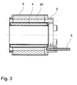
- Fig. 3
- a sectional view of the inventive electric motor and
- Fig. 4
- a plan view of the inventive electric motor.
In
Allgemein gilt aber, dass die Antriebsteile des Elektromotores in einem Motorgehäuse angeordnet sind, wobei mit dem Gehäuse auch ein Kupplungsstück verbunden ist, auf welches ein durch den Elektromotor anzutreibendes dentales oder medizinisches Instrument oder Gerät gesteckt werden kann. Das Kupplungsstück ist oftmals eine genormte Kupplung, um Austauschbarkeit auch mit anderen Systemen zu erreichen.In general, however, that the drive parts of the electric motor are arranged in a motor housing, wherein with the housing, a coupling piece is connected, on which a to be driven by the electric motor dental or medical Instrument or device can be plugged. The coupler is often a standard coupling to achieve interchangeability with other systems.
Des Weiteren weist der Elektromotor 1 eine in dem Motor beziehungsweise Motorgehäuse gelagerte Rotorwelle auf, hierfür sind entsprechende Motorlager in bekannter Weise vorgesehen. Der (nicht gezeigte) Rotor wird von dem Stator 2 umgeben. Der Stator 2 besteht dabei aus einem Rückschlusskörper 3 und einer mit Strom beaufschlagbaren Wicklung 4. In bekannter Weise besitzt der Rotor einen Permanentmagneten, der sich aufgrund des sich in der Wicklung 4 aufbauenden Magnetfeldes zu drehen beginnt. Dabei ist der Permanentmagnet des Rotors als zweipolig, diametral ausgerichteter Rotormagnet ausgeführt. Der Rückschlusskörper 3, der oftmals aus weichmagnetischen Material besteht, dient einer effektiven Führung des von der mit Strom beaufschlagten Wicklung 4 erzeugten Magnetfeldes.Furthermore, the
In dem hier gezeigten Ausführungsbeispiel ist die Wicklung 4 auf der Innenseite 33 des Rückschlusskörpers 3 vorgesehen. Zum Schutze der Wicklung 4 ist eine Schutzschicht oder Schutzhülse 40 vorgesehen, die zwischen Wicklung 4 und dem (nicht gezeigten) Rotor angeordnet ist. Diese z.B. als Schutzummantelung ausgebildete Schutzhülse 40 kann zum Beispiel eine Umspritzung der Wicklung 4 sein. Alternativ ist es natürlich auch möglich, die Wicklung 4 auf der Außenseite des Rückschlusskörpers 3 anzuordnen.In the embodiment shown here, the winding 4 is provided on the
An der Stirnseite 11 des Elektromotors 1 stehen mehrere Medienleitungen 5 parallel zur Längserstreckung des Elektromotors 1 hervor. Diese Medienleitungen 5 dienen zum Beispiel zum Leiten von Gasen, Luft, Wasser, Flüssigkeiten, Strom, Licht und so weiter.At the
Erfindungsgemäß wird vorgeschlagen, dass der Rückschlusskörper 3 die Medienleitungen 5 aufnimmt. In dem in
Der Begriff "Medienleitung" ist dabei sehr umfassend zu verstehen. Als Medienleitung wird dabei ein eigenes, abgeschlossenes System zum Leiten des Mediums verstanden, wie es zum Beispiel bei einem elektrischen Kabel vorgesehen ist, welches eine entsprechend isolierende Ummantelung aufweist. Der Begriff "Medienleitung" 5 kann aber auch so ausgelegt sein, dass die als Tunnel ausgebildete Durchführung 30 beziehungsweise die Bohrung oder der Kanal oder auch die Nuten 31, 32 selber Teil der Medienleitung 5 sind, insbesondere dann, wenn diese Teil eines Leitungssystemes für Wasser, Flüssigkeiten, Gas und so weiter ist.The term "media management" is to be understood very comprehensively. As a media line is understood to be a separate, closed system for conducting the medium, as provided for example in an electrical cable, which has a correspondingly insulating sheath. The term "media line" 5 can also be designed so that the trained as a
Gerade in
In
In
Die in
Die in den Ausführungsbeispielen gezeigten Rückschlusskörper 3 sind hülsenartig oder zylinderartig aufgebaut, ohne hierauf die Erfindung in irgendeiner Weise beschränken zu wollen. Sie können einstückig gefertigt sein oder aus verschiedenen Hülsensegmenten bestehen oder aber aus einer Vielzahl zu einem Paket zusammengestellter Rückschlussscheiben bestehen, die unter sich gleichartig beziehungsweise identisch sind.The
Die Ausgestaltung des Rückschlusskörpers 3 ist dabei an eine zylinderförmige Ausgestaltung nicht gebunden, insbesondere die Außenkontur des Rückschlusskörpers kann oval oder auch rechteckig gebildet sein.The design of the
Auf der Außenseite des Elektromotors 1 ist eine hülsenartige Ummantelung 10 vorgesehen, die entweder eine Schutzfunktion für den Elektromotor hat oder auch Teil des Motorgehäuses sein kann.On the outside of the
In
Die jetzt mit der Anmeldung und später eingereichten Ansprüche sind Versuche zur Formulierung ohne Präjudiz für die Erzielung weitergehenden Schutzes.The claims now filed with the application and later are attempts to formulate without prejudice to the attainment of further protection.
Sollte sich hier bei näherer Prüfung, insbesondere auch des einschlägigen Standes der Technik, ergeben, daß das eine oder andere Merkmal für das Ziel der Erfindung zwar günstig, nicht aber entscheidend wichtig ist, so wird selbstverständlich schon jetzt eine Formulierung angestrebt, die ein solches Merkmal, insbesondere im Hauptanspruch, nicht mehr aufweist.If, on closer examination, in particular also of the relevant prior art, it appears that one or the other feature is beneficial for the purpose of the invention, but not of decisive importance, it is of course already desired to formulate such a feature , in particular in the main claim, no longer having.
Die in den abhängigen Ansprüchen angeführten Rückbeziehungen weisen auf die weitere Ausbildung des Gegenstandes des Hauptanspruches durch die Merkmale des jeweiligen Unteranspruches hin. Jedoch sind diese nicht als ein Verzicht auf die Erzielung eines selbständigen, gegenständlichen Schutzes für die Merkmale der rückbezogenen Unteransprüche zu verstehen.The references cited in the dependent claims indicate the further development of the subject matter of the main claim by the features of the respective subclaim. However, these are not to be understood as a waiver of obtaining independent, objective protection for the features of the dependent claims.
Merkmale, die bislang nur in der Beschreibung offenbart wurden, können im Laufe des Verfahrens als von erfindungswesentlicher Bedeutung, zum Beispiel zur Abgrenzung vom Stand der Technik beansprucht werden.Features that have hitherto been disclosed only in the description may be claimed in the course of the method as of essential importance to the invention, for example to distinguish from the prior art.
Merkmale, die nur in der Beschreibung offenbart wurden, oder auch Einzelmerkmale aus Ansprüchen, die eine Mehrzahl von Merkmalen umfassen, können jederzeit zur Abgrenzung vom Stande der Technik in den ersten Anspruch übernommen werden, und zwar auch dann, wenn solche Merkmale im Zusammenhang mit anderen Merkmalen erwähnt wurden beziehungsweise im Zusammenhang mit anderen Merkmalen besonders günstige Ergebnisse erreichen.Features which have been disclosed only in the description, or also individual features of claims comprising a plurality of features, may at any time be included in the first claim for distinction from the prior art, even if such features are associated with others Characteristics were mentioned or achieve particularly favorable results in connection with other features.
Claims (15)
Applications Claiming Priority (1)
| Application Number | Priority Date | Filing Date | Title |
|---|---|---|---|
| DE102007062541A DE102007062541A1 (en) | 2007-12-20 | 2007-12-20 | electric motor |
Publications (2)
| Publication Number | Publication Date |
|---|---|
| EP2073347A2 true EP2073347A2 (en) | 2009-06-24 |
| EP2073347A3 EP2073347A3 (en) | 2015-08-05 |
Family
ID=40409893
Family Applications (1)
| Application Number | Title | Priority Date | Filing Date |
|---|---|---|---|
| EP08022027.0A Withdrawn EP2073347A3 (en) | 2007-12-20 | 2008-12-18 | Electric motor |
Country Status (4)
| Country | Link |
|---|---|
| US (1) | US8110960B2 (en) |
| EP (1) | EP2073347A3 (en) |
| JP (1) | JP2009153376A (en) |
| DE (1) | DE102007062541A1 (en) |
Families Citing this family (13)
| Publication number | Priority date | Publication date | Assignee | Title |
|---|---|---|---|---|
| US8643233B2 (en) * | 2008-07-28 | 2014-02-04 | Tm4 Inc. | Multi-path liquid cooling arrangement for electric machines |
| PL2325977T3 (en) | 2009-11-23 | 2012-12-31 | Abb Schweiz Ag | Stator and assembly method |
| CN102244434B (en) * | 2010-05-11 | 2016-04-06 | 德昌电机(深圳)有限公司 | Electric machine assembly |
| CN102068315B (en) * | 2011-01-06 | 2014-04-30 | 中国航空工业集团公司西安飞行自动控制研究所 | Electric motor for dental treatment |
| US20120318479A1 (en) * | 2011-06-14 | 2012-12-20 | Fukuta Electric & Machinery Co., Ltd. | Liquid cooled motor assembly and cover thereof |
| DE102011082353B4 (en) * | 2011-09-08 | 2021-04-01 | Siemens Aktiengesellschaft | Stator for an electric motor |
| US8901790B2 (en) * | 2012-01-03 | 2014-12-02 | General Electric Company | Cooling of stator core flange |
| JP5527910B2 (en) * | 2012-09-24 | 2014-06-25 | 株式会社ナカニシ | Dental handpiece drive motor and dental treatment system |
| US9803931B2 (en) * | 2012-12-05 | 2017-10-31 | Micro-Nx Co., Ltd | Handpiece with slim driving part of direct cooling type |
| DE102013208746A1 (en) * | 2013-05-13 | 2014-11-13 | Robert Bosch Gmbh | Stator for an electric machine that extends concentrically about a central axis and method for producing such |
| EP3176927B1 (en) * | 2014-07-31 | 2022-01-26 | Nakanishi Inc. | Electric motor and dental device |
| EP3852667A4 (en) * | 2018-09-17 | 2022-06-15 | Covidien LP | Surgical robotic systems |
| DE102020119635A1 (en) | 2020-07-24 | 2022-01-27 | Sycotec Gmbh & Co. Kg | Electric motor for dental and medical purposes |
Family Cites Families (14)
| Publication number | Priority date | Publication date | Assignee | Title |
|---|---|---|---|---|
| DE2613061C3 (en) * | 1976-03-26 | 1984-06-14 | Siemens AG, 1000 Berlin und 8000 München | Drive motor for a dental handpiece and contra-angle |
| DE3237650A1 (en) * | 1981-10-12 | 1983-05-11 | Kabushiki Kaisha Morita Seisakusho, Kyoto | MICRO MOTOR WITH BUILT-IN COOLANT PIPES |
| US5365132A (en) * | 1993-05-27 | 1994-11-15 | General Electric Company | Lamination for a dynamoelectric machine with improved cooling capacity |
| DE19604628A1 (en) * | 1996-02-08 | 1997-08-14 | Kaltenbach & Voigt | DC motor for driving a dental instrument |
| DE19640020A1 (en) * | 1996-09-27 | 1998-04-02 | Heribert Schmid | Electric motor esp for dental drill |
| DE29717128U1 (en) * | 1997-09-25 | 1997-11-20 | System Antriebstechnik Dresden | Caseless three-phase machine with axially parallel coolant pipes in the stator core package |
| DE19757605C2 (en) * | 1997-12-23 | 2003-03-13 | Siemens Ag | Electric motor with cooling |
| DE19843951C2 (en) * | 1998-05-26 | 2002-03-14 | Kaltenbach & Voigt | Drive system for dental handpieces |
| US7211919B2 (en) * | 1999-08-16 | 2007-05-01 | American Superconductor Corporation | Thermally-conductive stator support structure |
| ITBO20010051A1 (en) * | 2001-01-31 | 2002-07-31 | Castellini Spa | DENTAL HANDPIECE, IN PARTICULAR FOR DENTAL UNITS |
| US6819016B2 (en) * | 2002-07-18 | 2004-11-16 | Tm4 Inc. | Liquid cooling arrangement for electric machines |
| JP4743786B2 (en) * | 2003-07-10 | 2011-08-10 | マグネティック アプリケーションズ インコーポレイテッド | Compact high-power alternator |
| US6960851B2 (en) * | 2003-12-02 | 2005-11-01 | Tm4 Inc. | Cooling device including a biasing element |
| DE102006005316B4 (en) * | 2006-02-06 | 2020-03-26 | Siemens Aktiengesellschaft | Cooling device for an electrical machine, electrical machines with such a cooling device, dynamo sheet and manufacturing processes for such electrical machines |
-
2007
- 2007-12-20 DE DE102007062541A patent/DE102007062541A1/en not_active Withdrawn
-
2008
- 2008-12-17 US US12/314,820 patent/US8110960B2/en not_active Expired - Fee Related
- 2008-12-18 EP EP08022027.0A patent/EP2073347A3/en not_active Withdrawn
- 2008-12-22 JP JP2008326309A patent/JP2009153376A/en active Pending
Also Published As
| Publication number | Publication date |
|---|---|
| US20090160269A1 (en) | 2009-06-25 |
| US8110960B2 (en) | 2012-02-07 |
| EP2073347A3 (en) | 2015-08-05 |
| DE102007062541A1 (en) | 2009-06-25 |
| JP2009153376A (en) | 2009-07-09 |
Similar Documents
| Publication | Publication Date | Title |
|---|---|---|
| EP2073347A2 (en) | Electric motor | |
| DE4238564C2 (en) | Power tool | |
| EP1993463B1 (en) | Handpiece for dentists, dental surgeons, or dental technicians, comprising an electric motor | |
| WO1994006196A1 (en) | Electric motor | |
| DE10033577A1 (en) | Small brushless motor e.g. for rotating medical cutting or grinding instrument, comprises rear support for covering rear opening of outer housing and conducting connections penetrating outwards from rear side of coil unit | |
| EP0660492B1 (en) | Cooling system for a motor | |
| DE3928985A1 (en) | WORKPIECE SPINDLE ARRANGEMENT FOR A LATHE | |
| EP2073359A1 (en) | Tube motor | |
| DE2613061A1 (en) | DRIVE MOTOR FOR A DENTAL HANDLE AND ANGLE PIECE | |
| EP0888091B2 (en) | Dental tool holder | |
| DE2203586A1 (en) | STORAGE OF AN ELECTRIC MOTOR DIRECTLY DRIVING A SPINNING ORGAN | |
| EP2073349B1 (en) | Electrical motor with media conduits through the stator | |
| DE3237650A1 (en) | MICRO MOTOR WITH BUILT-IN COOLANT PIPES | |
| DE102011052085A1 (en) | Permanent magnet synchronous machine for e.g. electric vehicle, has two conduits for passing and discharging cooling mediums respectively in rotor | |
| DE19820464A1 (en) | Oscillating electric motor especially for providing reciprocating motion on textile machines | |
| EP0788779B1 (en) | D.C. Motor for driving a dental instrument | |
| EP1753113B1 (en) | Stator molding | |
| EP2295621B1 (en) | Friction motor spindle | |
| EP1045505A2 (en) | Cooled electric disk motor | |
| DE19714466A1 (en) | Electric motor especially for dental tool | |
| WO2009049807A1 (en) | Electric motor for use in a dentist's, dental surgeon's or dental technician's hand piece | |
| DE10225221B4 (en) | Ventilation of a ring motor for a tube mill | |
| CH693014A5 (en) | Rotor for electric micro motor with stator with at least two windings has rotor section with permanent magnet irreversibly attached to two ends of divided rotor shaft | |
| EP0431244A1 (en) | Stranding machine for the continuous stranding of electrical cables and lines | |
| DE3527796A1 (en) | Electrical drive system for a dental handpiece |
Legal Events
| Date | Code | Title | Description |
|---|---|---|---|
| PUAI | Public reference made under article 153(3) epc to a published international application that has entered the european phase |
Free format text: ORIGINAL CODE: 0009012 |
|
| AK | Designated contracting states |
Kind code of ref document: A2 Designated state(s): AT BE BG CH CY CZ DE DK EE ES FI FR GB GR HR HU IE IS IT LI LT LU LV MC MT NL NO PL PT RO SE SI SK TR |
|
| AX | Request for extension of the european patent |
Extension state: AL BA MK RS |
|
| PUAL | Search report despatched |
Free format text: ORIGINAL CODE: 0009013 |
|
| AK | Designated contracting states |
Kind code of ref document: A3 Designated state(s): AT BE BG CH CY CZ DE DK EE ES FI FR GB GR HR HU IE IS IT LI LT LU LV MC MT NL NO PL PT RO SE SI SK TR |
|
| AX | Request for extension of the european patent |
Extension state: AL BA MK RS |
|
| RIC1 | Information provided on ipc code assigned before grant |
Ipc: H02K 7/14 20060101ALI20150630BHEP Ipc: H02K 5/22 20060101ALN20150630BHEP Ipc: H02K 11/00 20060101ALN20150630BHEP Ipc: A61C 17/28 20060101ALI20150630BHEP Ipc: H02K 1/20 20060101AFI20150630BHEP Ipc: H02K 3/47 20060101ALI20150630BHEP Ipc: A61C 1/06 20060101ALI20150630BHEP |
|
| AKY | No designation fees paid | ||
| AXX | Extension fees paid |
Extension state: AL Extension state: BA Extension state: MK Extension state: RS |
|
| REG | Reference to a national code |
Ref country code: DE Ref legal event code: R108 |
|
| STAA | Information on the status of an ep patent application or granted ep patent |
Free format text: STATUS: THE APPLICATION IS DEEMED TO BE WITHDRAWN |
|
| 18D | Application deemed to be withdrawn |
Effective date: 20160206 |