EP2073227B1 - Compact and robust control for medium- and high-voltage electric devices - Google Patents
Compact and robust control for medium- and high-voltage electric devices Download PDFInfo
- Publication number
- EP2073227B1 EP2073227B1 EP08171621A EP08171621A EP2073227B1 EP 2073227 B1 EP2073227 B1 EP 2073227B1 EP 08171621 A EP08171621 A EP 08171621A EP 08171621 A EP08171621 A EP 08171621A EP 2073227 B1 EP2073227 B1 EP 2073227B1
- Authority
- EP
- European Patent Office
- Prior art keywords
- closing
- plate
- switch
- opening
- control
- Prior art date
- Legal status (The legal status is an assumption and is not a legal conclusion. Google has not performed a legal analysis and makes no representation as to the accuracy of the status listed.)
- Not-in-force
Links
Images


Classifications
-
- H—ELECTRICITY
- H01—ELECTRIC ELEMENTS
- H01H—ELECTRIC SWITCHES; RELAYS; SELECTORS; EMERGENCY PROTECTIVE DEVICES
- H01H3/00—Mechanisms for operating contacts
- H01H3/22—Power arrangements internal to the switch for operating the driving mechanism
- H01H3/30—Power arrangements internal to the switch for operating the driving mechanism using spring motor
- H01H3/3005—Charging means
- H01H3/3026—Charging means in which the closing spring charges the opening spring or vice versa
-
- H—ELECTRICITY
- H01—ELECTRIC ELEMENTS
- H01H—ELECTRIC SWITCHES; RELAYS; SELECTORS; EMERGENCY PROTECTIVE DEVICES
- H01H3/00—Mechanisms for operating contacts
- H01H3/22—Power arrangements internal to the switch for operating the driving mechanism
- H01H3/30—Power arrangements internal to the switch for operating the driving mechanism using spring motor
- H01H3/3052—Linear spring motors
-
- H—ELECTRICITY
- H01—ELECTRIC ELEMENTS
- H01H—ELECTRIC SWITCHES; RELAYS; SELECTORS; EMERGENCY PROTECTIVE DEVICES
- H01H3/00—Mechanisms for operating contacts
- H01H3/22—Power arrangements internal to the switch for operating the driving mechanism
- H01H3/30—Power arrangements internal to the switch for operating the driving mechanism using spring motor
- H01H2003/3073—Indication of the charge on the spring motor
-
- H—ELECTRICITY
- H01—ELECTRIC ELEMENTS
- H01H—ELECTRIC SWITCHES; RELAYS; SELECTORS; EMERGENCY PROTECTIVE DEVICES
- H01H3/00—Mechanisms for operating contacts
- H01H3/22—Power arrangements internal to the switch for operating the driving mechanism
- H01H3/30—Power arrangements internal to the switch for operating the driving mechanism using spring motor
- H01H2003/3078—Power arrangements internal to the switch for operating the driving mechanism using spring motor using an inertia element, e.g. a flywheel, to controll the energy released by the spring
-
- H—ELECTRICITY
- H01—ELECTRIC ELEMENTS
- H01H—ELECTRIC SWITCHES; RELAYS; SELECTORS; EMERGENCY PROTECTIVE DEVICES
- H01H3/00—Mechanisms for operating contacts
- H01H3/22—Power arrangements internal to the switch for operating the driving mechanism
- H01H3/30—Power arrangements internal to the switch for operating the driving mechanism using spring motor
- H01H3/3031—Means for locking the spring in a charged state
Definitions
- the present invention relates to mechanical controls for medium and high voltage electrical equipment.
- Such mechanical controls are known for example from the document EP 0 651 409 and document EP 1 178 505 .
- These commands comprise several levers able to be rotated by means of an energy stored in springs, to cause the opening and closing of a switch.
- a lever is provided for transmitting a closing force of the switch, a lever for transmitting an opening force of the switch, a lever for acting directly on the switch, a lever for locking the switch in the closed position and a lever allowing a damping of the command during a closing operation of the switch.
- This command has a very large footprint, a high realization complexity, and their cost is high.
- control is connected to the switch, so that the control and the switch are biased by additional transverse stresses that may reduce the life of the switch or control.
- an opening and closing switch control having a platen, rotatably mounted on a mounting plate by means of a main shaft, the switch being mechanically connected to said platen, and means for opening and closing the switch, as well as means for locking the switch in the closed position and this substantially in the same plane. All the forces being transmitted by the plate and applying in the plane of the plate, and not by the tree, the constraints on the tree are reduced. Thus the main shaft can be expected smaller and its connection with the deck simpler. This decreases the cost of the order.
- the closing means of the switch comprise a cam cooperating with the plate to tilt and cause the closing of the switch.
- This cam is integral in rotation with a drive wheel, this wheel being driven by a spring fixed on the one hand to the wheel and on the other hand to the mounting plate so that the spring overlaps the plate. The order is then made even more compact.
- the control therefore uses a single lever plate to perform the various functions, which reduces the dimensions, including the depth of control. This therefore makes it possible to arrange the closing spring in a plane parallel to that lever, the spring is then superimposed on the lever.
- the grouping of several levers in a single plate and the particular arrangement of the closing spring makes it possible to obtain particularly compact control.
- the opening force of the switch is applied to the plate by a spring which transmits it to the movable element of the switch, the latter having a displacement along its axis to reduce unwanted transversal stresses.
- the storage of the mechanical energy of opening, the systems for holding and releasing the energy of opening and the transmission of energy are carried out in a same plane. and movement via a link mechanism to the movable terminal of the circuit breaker.
- the force transmission means comprises for example a cam rotatably mounted on a closing shaft parallel to the main shaft, intended to come into contact with a second zone of the plate to apply a tilting force to the plate around the plate.
- main shaft in a first direction of rotation to cause the closing of the switch
- said cam being rotatably connected to a drive disk adapted to be rotated by elastic energy storage means comprising a closing spring, said closing spring being mechanically connected by a first end to the mounting plate and a second end to the drive disk, so that the first end of the closing spring is disposed on one side of the platen and the second end is arranged on another side of the plate on either side of a plane, said median plane, containing the axis of the main shaft and orthogonal to an axis of displacement of the moving part when the closing spring is in a loaded state.
- This arrangement advantageously makes it possible to reduce the height of the control due to the overlap of the plate by the spring
- the movable part is advantageously arranged opposite the axis of the closing shaft of the drive disk relative to a plane containing the axis of the main shaft, orthogonal to the plate and orthogonal to the median plane.
- the opening actuator may comprise an opening spring adapted to drive the plate in a second direction of rotation opposite the first direction of rotation, to cause the opening of said switch, the opening spring being mounted on the same face. of the mounting plate that the plate, the closing spring being disposed on another face of the mounting plate, the opening spring having a first end attached to the mounting plate on the same side as that of the first end of the mounting plate; closing spring with respect to the median plane and a second end fixed to the plate.
- the closing spring and the opening spring work in tension.
- the axis of the main shaft is advantageously arranged between the axis of displacement of the movable part and an axis substantially parallel to this axis and passing through the axis of the closing shaft, this arrangement makes it possible to make the order still more compact.
- the axis of the opening spring advantageously forms an angle of about 45 ° with respect to a horizontal direction, which allows to arrange the control either horizontally or vertically, without its operation being altered.
- the first end of the closing spring is for example disposed between the first end of the opening spring and a plane containing the axis of movement of the movable part and orthogonal to the mounting plate.
- the width of the control is advantageously reduced.
- the axis of the closing shaft may be disposed on one side of the median plane opposite the first end of the closing spring of the main shaft.
- the control may also comprise means for damping the rotation of the plate under the action of the opening spring.
- damping means are advantageously arranged inside the opening spring, which simplifies assembly.
- the movable part may comprise an end intended to be connected to a movable element of the switch disposed substantially at the same level as the maximum position reached by the outer periphery of the cam radially opposite the contact zone with the plate.
- the closing locking means are preferably arranged opposite to the moving part intended to be mechanically connected to the switch relative to the axis of the main shaft.
- the four zones are advantageously distributed around the main shaft substantially equidistant from the main shaft.
- the control may comprise a fifth zone intended to be connected to indicator state means of the switch, said zone being provided between the third and the fourth zone.
- the first zone and the fourth zone are for example disposed substantially opposite to the main shaft, and the second zone and the third zone are arranged substantially opposite to the main shaft.
- the first and third zones may also be arranged on the same side of a plane containing the axis of the main shaft and parallel to the axis of displacement of the moving part, the fourth and the second zone being disposed of a other side of this plan.
- the closure locking means advantageously cooperate with an actuating lever rotatably mounted on the plate at the fourth zone.
- the control may comprise means for charging the closing spring, said means comprising means for rotating the drive disc in the same direction as that of the rotation caused by the release of energy stored in the closing spring, said means for loading the closing spring being disposed substantially opposite the movable piece relative to a plane containing the axis of the drive disk and substantially parallel to the moving part.
- the control may comprise stop means for stopping the means for loading the closing spring when the required load of the spring of closing is reached, said stop means comprising a wheel integral in rotation with the drive disc, said wheel comprising a recess at its perimeter, said recess being able to cooperate with a mechanism for deactivating the loading means, said recess being angularly oriented relative to the drive disk to correspond to a rotation of the drive disk corresponding to the required load.
- the means for charging the closing spring are for example driven by an electric motor, the deactivating means forming a switch capable of interrupting the power supply of said motor.
- the control may also include means for isolating the means for loading the closing spring of the drive disc as soon as the drive disc has reached a top dead center corresponding to the required load of the closing spring, these means being formed by at least one tooth of the drive disc radially retractable, which simplifies the control.
- the control may also comprise opening locking means adapted to exert a force of immobilization on the drive disk in the loaded position of the closing spring.
- the opening locking means are for example arranged between the drive disc and the closing locking means, which makes it possible to increase the compactness and to be able to control both the locking means closing and manually opening locking means with a single lever.
- the control advantageously comprises manual actuation means capable of alternately releasing the opening locking means and the closing locking means to allow the closing and opening of the switch respectively.
- manual actuation means capable of alternately releasing the opening locking means and the closing locking means to allow the closing and opening of the switch respectively.
- the implementation of common manual means simplifies the order.
- the manual actuating means comprise for example a lever rotatably mounted on the mounting plate, able to be actuated at a first end and intended to come into contact with one end with a lever of the opening locking means. and at another end with a lever closure locking means for tilting said levers and allow the release of the closing energy and the opening energy respectively.
- the lever may comprise a first portion and a second portion, the first portion carrying a second end capable of cooperating with the lever adapted to deactivate the opening locking means, and the second portion having a suitable radial projection. to cooperate with the lever adapted to disable the closing locking means.
- the closing locking means and the opening locking means can be mounted on either side of the mounting plate.
- Said state indicator means comprise, for example, position indicator electrical switches, a visual position indicator and means for locking a lever of the opening locking means, the position indicator electrical switches, the visual position indicator and the locking means being connected to the plate by connecting rods.
- the moving part connecting the plate to the element of the switch is advantageously a force transmission rod forming an angle of between 60 ° and 90 ° with the straight line connecting the axis of the main shaft and the point of attachment of the transmission rod of force on the plate, the angle of 60 ° corresponding to a closed state of the switch and the angle of 90 ° corresponding to an open state of the switch.
- the plate is for example distributed in at least two parallel planes.
- the plate can also include several levers mechanically assembled in a fixed manner.
- the present invention also relates to medium and high voltage electrical equipment comprising a switch provided with a movable contact in translation and a fixed pole, and a control according to the present invention.
- the electrical equipment according to the invention may comprise a connecting rod system for connecting the plate to the mobile pole in translation of the switch, or
- the first zone of the plate may comprise an oblong slot in which is intended to be mounted with play an end of an element rigidly connected to the mobile pole in translation of the switch.
- the first zone comprises a toothed angular sector intended to mesh with a toothed portion rigidly connected to the movable pole in translation of the switch.
- the control is advantageously arranged in the axis of displacement in translation of the moving contact of the switch, which reduces the footprint of the equipment.
- the angle between the axis of the moving part and the axis of displacement of the movable contact is for example less than 5 °.
- the height of the control is defined as the dimension in the vertical direction on the Figure 1A , the width, the dimension in the horizontal direction and the thickness the dimension along an axis perpendicular to the plane of the sheet of the Figure 1A .
- FIG. 1A an exemplary embodiment of a mechanical control C of a switch, in particular a circuit breaker according to the present invention, can be seen.
- This command comprises two mounting plates 2, only one of which is visible on the Figure 1A , between which is rotated a plate 4 by means of a main shaft 6, the plate 4 is disposed substantially parallel to the mounting plates 2.
- the main shaft 6 is rotatably mounted between the two parallel mounting plates 2 by means of bearings.
- the main shaft 6 is rotatably mounted between the two parallel mounting plates 2 by means of bearings.
- the plate 4 is intended to transmit forces between different actuators and a switch (not shown).
- the main shaft 6 passes through the plate 4 substantially in a central portion thereof and is secured in rotation thereto by means of splines in the example shown.
- Other types of connection between the shaft 6 and the plate 4 are possible, for example by the use of hexagonal profiles, since no torque is transmitted to the shaft 6.
- the plate 4 has substantially the shape of a pentagon having five sides 10.1, 10.2, 10.3, 10.4, 10.5, two sides 10.1 and 10.2 of which form a concave angle 12.1 (FIG. Figure 2A ).
- Each of the vertices 12.1, 12.2, 12.3, 12.4, and 12.5 is connected to means able to exert or receive a force on or platinum.
- the top 12.3 is connected to the switch via a force transmission rod 14 rotatably mounted at the top 12.3.
- the top 12.4 is intended to receive a force exerted by a rotary actuator causing the tilting of the plate in the closing direction of the switch, hereinafter referred to as closing actuator 100.
- a roller 16 rotatably mounted at the top 12.4 is advantageously provided and is intended to come into contact with a rotary cam which will be described below, to reduce the frictional forces.
- the top 12.5 comprises an operating lever 20 intended to cooperate with locking means in the closed position 200 of the plate 4.
- the top 12.1 is connected to indicator means 300 of different positions taken by the switch.
- the top 12.2 is connected to an actuator intended to cause the plate to tilt in a direction of opening of the switch, hereinafter referred to as the opening actuator 400.
- the vertices 12.2, 12.3, 12.4 and 12.5 are substantially at the same distance from the main shaft 6. But other embodiments are possible to obtain specific transmission ratios.
- the vertices 12.2 and 12.4 are substantially symmetrical with respect to the main shaft 6, as well as the vertices 12.3 and 12.5.
- a judicious choice of angles makes it possible in particular to avoid collisions between the different units functional (platinum, springs, ratchet, cam) and to influence the reports of transmissions.
- the top 12.1 is advantageously concave, to avoid collisions between the plate and the opening spring.
- the plate 4 comprises two parallel plates 4.1, 4.2 visible on the Figure 2B fixed in rotation to the main shaft 6, these plates 4.1, 4.2 being for example 20 mm apart.
- the plane of the plate designates, in the case of a plate formed by a sheet metal plate, the plane containing the plate, and in the case where the plate is formed by several plates, for example two parallel plates 4.1, 4.2 as in the example shown, any plane located between the two plates, parallel thereto.
- the plate can then be made in such a way that it is actually contained in several parallel planes arranged close to each other. Indeed, it can be provided that the plate is made by stamping a sheet, or molding a metal alloy, or even by welding or screwing several levers, in order to achieve a plate formed of a set of different levers contained in several parallel planes, for example 20 mm apart.
- This particular configuration in several close superimposed planes does not cause significant stress on the main shaft 6, so it is not necessary to provide a large diameter shaft for holding with mechanical stresses. important.
- the control according to the invention always offers great compactness in height and width.
- the plane of the plate designates any plane situated in this interval 20 mm and parallel to the two plates 4.1, 4.2.
- the closing actuator 100 shown in isolation is visible on the Figures 3A and 3B .
- the closing actuator 100 comprises a cam 102 rotatably mounted on the mounting plate 2 by a shaft 104, called a closing shaft, by means of bearings 103.
- the closing cam 102 is parallel to the mounting plate 2 and has substantially the shape of a crescent rotatably fixed on the shaft 104 at a point 105 connecting a portion of greater curvature 106 of the cam 102 and a part of smaller curvature 108.
- the closure cam 102 is intended to come into contact with the roller 16 carried by the plate 4, on the contact zone defined between the tip 105 and the tip 110 on the side of the zone of the greatest curvature 106.
- the contact between the contact zone 106 and the roller 16 causes tilting of the plate 4 in a direction of closure of the contactor, in the example shown, this corresponds to a rotation in the counterclockwise direction of the plate 4 around the main shaft 104.
- the actuator 100 comprises driving means 112, formed by elastic means, in the example shown a helical spring 114, said closing spring.
- the spring 114 is mounted by a first end 114.1 free to rotate on the mounting plate 2 and a second end 114.2 on a drive disc 116 integral in rotation with the closing cam 102, also free to rotate.
- the drive disc 116 is fixedly rotatably mounted on the shaft 104.
- the closing spring 114 works in tension.
- the spring 114 more precisely its longitudinal axis is disposed in a plane parallel to that of the plate 4 and overlaps it. Indeed, the first end 114.1 fixed to the mounting plate 2 is located below the plate 4, and the second end 114.2 attached to the drive disc 116 is located above the plate. Thus the plane containing the axis of the closing spring 114 is superimposed on the plane of the plate 2. Thus, there is obtained a control whose transverse dimensions are reduced, including its height and width. In addition, the use of a single plate combining several functions is made possible, as will be explained in the following description, to reduce the thickness of the command.
- the drive disk 116 is disposed above the plate 4 in the representation of the control.
- the closing spring 114 is arranged to be positioned substantially along a diameter of the drive disk 116, its first end 114.1 being fixed on the mounting plate 2 opposite the drive disk 116 relative to the plate 4.
- the closing spring 114 extends substantially over the entire height of the control in the representation of the Figure 1A .
- the closing spring 114 is intended to store elastic energy which, when it is released, drives the driving disk 116 in a clockwise rotation around the shaft 104, as well as the closing cam 102. .
- the closing spring 114 is thus disposed in the control, so that the release of the elastic energy causes the rotation of the drive disk 116 in a clockwise direction causing the closing of the switch.
- the loading of the closing spring 114 is carried out by clockwise rotation of the driving disc 116 around the shaft 104 by means of a rotary electric motor 118 which drives a gear train 120, one of which meshes with toothed perimeter 116.1 of the drive disk 116.
- the electric motor 118 and the gear train 120 are arranged on one side of the drive disk 116 opposite the force transmission rod with respect to the plate 4.
- the motor 118 drives the drive disk via the gear 120 which reduces the rotation of the motor 118.
- the gear comprises a freewheel coupling device (not shown), an exemplary embodiment of which is known from FIG. document EP1408522 , allowing the disk 116 to rotate rapidly during a switching operation without driving the motor.
- the drive disk 116 further includes a retractable section (not shown) which decouples the motor 118 and the drive disk 116 as soon as the drive disk 116 has passed the top dead center position of the closing spring. 114.
- the top dead center is the full load position of the closing spring 114.
- the retractable section is for example known from the document EP1369886 .
- the disconnector is closed driven by the closing spring 114 via the drive disk 116, the closing cam 102 and the plate 4.
- the driving disk 116 rotates until the inertia of it is stored in the closing spring 114.
- the motor 118 is activated earlier.
- the freewheeling coupling device couples the drive disk and the motor as soon as the rotational speed of the drive disk has decreased to the reduced rotational speed of the motor 118.
- the motor drives the drive disk. drive 116 to the top dead center of the closing spring 114. Beyond this top dead center, the closing spring 114 drives the driving disc 116 until it is stopped by the opening lock 600.
- the motor and the gear are then decoupled from the wheel 116 by the section retractable.
- the motor 118 is stopped by the switch 124, switched by the lever 126, the position of which is controlled by the shape of the disk 130.
- This example of driving in rotation of the drive disk 116 is in no way limiting and any other drive means may be suitable.
- the spring 114, the motor 118 and the gearset 120 may be replaced by a hydraulic or pneumatic system or by an electric motor connected to the actuator 100.
- the actuator 100 also comprises means 122 for switching off or energizing the motor and for controlling the load of the closing spring 114.
- These means 122 comprise a switch 124 capable of interrupting the power supply of the motor when the required load of the closing spring 114 is reached.
- the switch 124 is connected to a lever 126 by a transmission bar 128, the lever 126 being rotated when the required load is reached.
- the lever 126 is rotatably mounted on the mounting plate 2 and is intended to come into contact with an angular zone 130.1 of a control wheel 130 which is coaxial with the drive disc 116, and integral in rotation therewith.
- the angular zone 130.1 forms a recess on the outer periphery of the control wheel 130 radially inwardly
- the lever 126 can then occupy two positions, a first position in which a free end 126.1 of the lever is in contact with the circular periphery of the control wheel 130 (shown in dashed line on the Figure 1A ) and a second position in which the free end 126.1 of the lever enters the recess 130.1 (shown in solid line on the Figure 1A ).
- the lever 126 is resiliently biased into contact with the control wheel 130 by a torsion spring 132.
- the control wheel is advantageously sized to form a mass of inertia.
- a visual indicator 134 of the spring load is also provided in the form of a disc rotatably connected to the lever 126, this disc is visible from the outside.
- the disc 134 has visual cues corresponding to the loaded / unloaded position of the spring 114
- the closure actuator 100 has the advantage of being safe and robust.
- the means for loading the spring 114 combines the means for loading the spring 114, the mass of inertia which makes it possible to control the time and the closing speed of the contactor, the control means of the electric motor for the loading of the closing spring 114 and the control a visual indicator of the load of the closing spring 114.
- the opening actuator 400 comprises means for storing elastic energy, these means are formed by a helical spring 402, called an opening spring, rotatably mounted by a first end 402.1 on the mounting plate 2 and by a second end 402.2 on the plate 2 at the angle 12.2.
- the opening spring 402 works in tension.
- the damping means 500 are provided inside the helical spring 402, and also fixed to the plate 4 at the angle 12.2.
- damping means 500 or brake are intended to damp the movement of the plate when the opening spring 402 causes the tilting of the plate 4 in a direction of opening of the contactor.
- Such means are well known to those skilled in the art and for example the document EP1130610 , and will not be described in detail.
- the first end 402.1 of the opening spring 402 is fixed on lower possible on the mounting plate 2 away from the plate 4, opposite the opening cam 102 relative to the plate 4.
- the opening spring / brake 402 is advantageously inclined at an angle of approximately 45 ° with respect to the vertical direction upwards and to the right of the Figure 1A .
- the plate 4 When the elastic energy stored by the opening spring 402 is released, the plate 4 is driven in a clockwise direction, causing an opening of the contactor.
- the opening spring 402 is a tension spring, which is loaded during a closing phase of the switch by tilting the plate 4 in the counterclockwise direction. This tilting causes a tension force at the second end 402.2 of the opening spring 402.
- closing locking means 200 which act on the plate 4 at the angle 12.5 and the opening locking means 600 which act directly on the drive disc 116.
- the locking means 200 and 600 are interposed between the opening spring 402 and the means for loading the closing spring 114.
- the closing locking means 200 are arranged at the bottom left of the plate 4, opposite the movable rod 14 with respect to the main axis 6.
- the locking means 200 are intended to immobilize the plate 4 in a closed position of the contactor against the force of the opening spring 402, which tends to tilt the plate 4 in a direction of opening of the contactor .
- the closing locking means 200 are such that they make it possible to immobilize the plate 4 subjected to a large torque by transforming it into a lower torque.
- the closing locking means 200 are arranged between the two mounting plates 2, since they cooperate directly with the lever 20 integral with the plate 4.
- the closing locking means 200 comprise a system of levers in series, supported by one end on the operating lever 20 rotatably mounted on the plate 4 at the angle 12.5.
- the locking means 200 comprise a first lever 202, rotatably mounted on the mounting plate 2, intended to come into contact with an end 202.1 with an end 20.1 of the operating lever 20.
- the opening spring 402 applies a force at the plate 4 in the clockwise direction, the plate 4 then transmits to the operating lever 20 a force which it transmits to the first lever 202, the direction of application of which does not pass through the axis of rotation of the first lever 202, a torque M1 is then generated.
- the locking means 200 comprise a second lever 204 rotatably mounted on the mounting plate 2, to which the first lever 202 applies a force by an end 202.2 on one end 204.1, in a direction not passing through the axis of rotation of the second lever 204, a torque M2 is then generated.
- the torque to which the second lever 204 is subjected and which tends to rotate it in the direction time is taken up by a puck 210 held stationary, forming a mechanical stop and able to be moved by electrical control means 212.
- the locking means also comprise a third lever 206 rotatably mounted on the mounting plate, intended to cooperate directly with the puck 210 for manual unlocking by a lever which will be described later.
- the electrical control means 212 comprise at least one electromagnet 214 capable of moving the puck 210 in order to release the second lever 204 in rotation in a clockwise direction, which releases in rotation the first lever 202, which releases the operating lever 20 and therefore the plate 4; it then switches in the clockwise causing the opening of the contactor.
- Torsion spring type return means are also provided on each of the levers 202, 204, 206 and on the pallet 210 to return them to the locking position.
- Rollers are advantageously provided on the levers at the ends intended to come into contact to reduce friction.
- the operating lever 20 carried by the plate 4 is also biased into position by a spring 24. Thus, when the plate 4 can resume its initial position during a closing step and be locked in position by the locking means in closing 200.
- the electrical control means 212 are actuated when the need to open the contactor is detected.
- the closing locking means 200 are arranged below the electric motor 118 and the drive wheel 116, laterally with respect to the plate 4.
- Opening locking means 600 are also provided.
- Figures 4A and 4C intended to immobilize the drive disk 116 against the force of the closing spring 114, which tends to tilt the plate 4 in a closing direction of the contactor. These are arranged in the example shown above the closing locking means 200.
- the opening locking means 600 similarly comprise the closing locking means 200 a lever system ensuring the recovery of the torque exerted by the closing spring 114 on the drive disk 116 by a puck (not visible) immobilized by electrical control means with respect to the mounting plate 2.
- the opening locking means 600 are mounted on the mounting plate 2 on the opposite side to that on which the closing locking means 200 are fixed.
- the lever system includes a first lever 604 for receiving a force from the drive disk 116, the first lever 604 being in position. contact by one end 604.1 with a roller 117 pivotable on the radially outer periphery of the drive disc 116.
- the force exerted by the closing spring 114 tends to rotate the drive disk 116, this force is applied to the first lever 604 in a direction not passing through its axis of rotation, a torque is then generated. This pair tends to rotate the first lever 604.
- the pair is taken up by a puck held stationary, forming a mechanical stop and able to be moved by an electrical control means 612.
- the opening locking means 600 also comprise a second lever 606 rotatably mounted on the mounting plate, intended to cooperate directly with the puck 610 for manual unlocking by a lever which will be described later.
- the electrical control means 612 comprise at least one electromagnet 614 capable of moving the puck to release a first lever 604 in rotation, which releases the drive disc 116, which then drives the plate 4 counterclockwise causing the closing contactor.
- Torsion spring type return means are also provided on each of the levers 604, 606 to return them to the locking position.
- a roller is also advantageously provided on the lever at the ends intended to come into contact, to reduce friction.
- the opening locking means 600 are arranged between the electric motor 118 and the closing locking means 200.
- the opening locking means 600 are arranged so as to be able to act on the drive disk 116 and are located in an orbital position with respect to the axis of rotation of the drive disc 116, which offers a certain degree of freedom to position the locking means.
- the plate is connected at its angle 12.1 to the indicator means 300 of different positions taken by the switch.
- the indicator means 300 comprise electrical position indicator switches 302 (only one is shown on the Figure 1A for the sake of clarity) arranged below the plate 4, a visual position indicator 308 in the form of a disc disposed between the switches 302 and the opening spring 402, and opening locking means locking.
- the switches 302 are controlled by the plate 4 by means of a connecting rod 304.
- Several switches 302, for example four are provided and controlled jointly by means of a bar connecting the four switches, this bar being itself connected to the connection bar 304.
- the visual indicator 308 is in the form of a disk adapted to be rotated by a connection rod 312 fixed free to rotate on the disk and on the plate 4. Thus a tilting of the plate 4 causes an angular displacement of the disk.
- the indicator 300 comprises a rod 314 controlling the movement of the locking lever in opening 604 by the locking lever 315.
- the lever 604 is blocked and can not release a closing maneuver if the switch is not completely in position d 'opening.
- Manual control means 700 of the locking means 200, 600 are also provided.
- These manual means 700 are particularly advantageously unique for the two locking means 200, 600. These comprise a lever 702 shown in solid lines in the rest position.
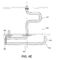
- lever 702 An embodiment of the lever 702 is shown from above on the figure 4E , the locking means in closing and opening are omitted for the sake of clarity.
- the lever 702 is rotatably mounted between the mounting plates 2 and between the two locking means 200, 600.
- the lever 702 has a first portion 703 intended to be the outside of the mounting plates 2 and a second portion 704 intended to be inside the two mounting plates 2
- the first portion 703 extends parallel to the mounting plate 2 and has a first end 705 of manual operation and a second end 706 to cooperate with the opening locking means 600, to unlock manually.
- the first end 705 is extended by the second portion 704, which extends substantially along the axis of rotation of the lever 702 and has a U-shaped radial projection 707 intended to cooperate with the closing locking means 200, to unlock them manually.
- the lever 702 in the clockwise direction (position A in dotted lines) by manipulating the first end 705, the end 707 of the second part 704 abuts against the lever 206, the lever 206 comes into contact with the lug 208 projecting from the pallet 210, it pivots in the clockwise manner identical to an electric actuation, which frees the closing locking system.
- the shape of the lever 702 makes it possible to interact on the two planes corresponding to the locking system in closing and opening.
- the connecting rod 14 is mounted on the top 12.3 disposed on a lateral end of the plate opposite the vertex 12.4 intended to receive the closing tilting force applied by the cam 102, with respect to the rotation shaft .
- the angle formed between the connecting rod 14 and the line connecting the vertex to the axis of the shaft 6 is advantageously between 60 ° and 90 ° depending on the open or closed state of the contactor. This range of values for this angle makes it possible to obtain a good transmission of effort.
- the plate 4, the cam 102, the opening spring 402 with the integrated damping means 500, the closing locking means 200 and the connecting rod 14 to the contactor are arranged in the same plane and are arranged so as not to interfere with each other when moving.
- the control is very compact and very robust, since it avoids the stresses in torsion of the main shaft.
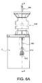
- FIG. 6A to 6C an exemplary embodiment of an apparatus comprising means for actuating the contactor allowing them to be mounted below the contactor and not on the side, as is customary in the apparatus of the state of the art, can be seen .
- These operating means can advantageously be associated with the control according to the present invention.
- the operating means 800 comprise an intermediate bar 802 rotatably connected at a first end 802.1 to an insulating bar 804 guided in translation along an axis Y by an insulating support column 806.
- An upper end of the insulating rod 804 is connected to a pole of the contactor (not shown), and a displacement in translation of the insulating rod 804 causes displacement of the pole relative to another pole of the contactor, in a direction of approach or distance of the two poles and thus in a direction of closing or opening of the contactor.
- guide sleeves 808 are also provided at an upper end 806.1 and at a lower end 806.2 of the column 806.
- the intermediate bar 802 is rotatably mounted a second end 802.2 opposite the first end 802.1 on a lever 810 which is mounted fixed in rotation on a control shaft 812.
- the system formed by the intermediate bar 802 and the lever 810 forms a system of rods transforming a rotational movement of the shaft into a translation movement of the insulating rod.
- the operating means 800 are particularly adapted to the control C according to the present invention shown on the Figures 1A to 5 , the shaft 812 is the shaft 6, the lever 810 is formed by the plate 4 and the intermediate bar 802 is formed by the force transmission rod 14 mounted free to rotate on the angle 12.3.
- actuating means 800 make it possible to achieve a seal only at the lower part 814 of the apparatus and not on all the apparatus.
- the actuating means 800 have the advantage of having few moving parts, these being also of reduced size.
- the maneuvering means are then very compact and consume little energy.
- the present operating means make it possible to avoid buckling of the insulating rod, which is caused by the compressive stresses applied by the devices of the state of the art. Indeed, the rotational movement of the shaft 812 is transformed in a simple manner in linear motion to be transmitted to the insulating rod 804.
- an insulating rod 904 is mounted slidable in an insulating support column 906 and is guided by sleeves 908 at the lower and upper ends of the column 906.
- the operating means 900 comprise a lever 902 fixedly mounted by a first end 902.1 rotated on a shaft 912 and a second end 902.2 rotatable on a lower end of the insulating rod 904.
- the mounting of the lever 902 on the insulating rod is performed with clearance by means of an oblong slot 910 to avoid transverse stresses of the insulating rod 904.
- the lever 902 is shown in two positions, a position I ', in which the contactor is open and a position II', in which the contactor is closed.
- the operating means 900 have the advantage of having few moving parts, these being also of reduced size.
- the maneuvering means are then very compact and consume little energy.
- the operating means 900 also have the advantage of less stressing the insulating rod in compression.
- the actuating means 900 are also particularly suitable for the control C according to the present invention shown in FIGS. Figures 1A to 5 , the shaft 912 is the main shaft 6, the lever 902 is formed by the plate 4 in which an oblong slot at the angle 12.3 is provided, the force transmission rod 14 and the insulating rod 904 are then rigidly related. On the Figure 6A , the command C is placed to the left of the operating means 900.
- an insulating rod 1004 is mounted slidable in an insulating support column 1006 and is guided by sleeves 1010 at the lower and upper ends of the column 1006.
- the actuating means comprise a lever 100 mounted rotatably by a first end 1002.1 on a shaft 1012.
- the lever 1002 comprises a toothed angular sector 1002.3 meshing with a lower end 1004.1 the insulating rod 1004 provided with a corresponding toothing 1004.2.
- a stop 1014 is provided at the lower end of the insulating rod 1004 in order to prevent the toothed sector from becoming more engaged with the toothed portion of the insulating rod.
- the operating means 1000 have the advantage of having few moving parts, these being also of reduced size.
- the maneuvering means are then very compact and consume little energy.
- the operating means 900 also have the advantage of less stressing the insulating rod in compression.
- the operating means 1000 are also particularly adapted to the control C according to the present invention shown in the Figures 1A to 5 , the shaft 1012 is the main shaft 6, the lever 1002 is formed by the plate 4 whose contour comprises a toothed sector at the angle 12.3, the force transmission rod 14 provided in the control C form the lower end of the insulating rod and forms with it a rigid assembly, for example by screwing.
- the control C is placed to the left of the operating means 1000.
- the toothed sector can advantageously be made directly on the plate 4.
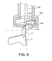
- the movement is guided in the disconnector by a rotary shaft 1102 constructed in the insulating support column of the disconnector as shown schematically on the figure 9 .
- the shaft 1102 crosses substantially perpendicularly a wall of the column 1103 in a sealed manner and is rotatable about its axis.
- the shaft 1102 is provided with two levers 1104, 1106 at each of its ends.
- the lever 1104, called the inner lever is mounted in the column 1103 and is mechanically connected to the insulating rod 1108.
- the lever 1106, called the external lever is arranged outside the column and is mechanically connected to the transmission rod of effort 14 connected to the plate 4.
- the 1106 external lever transforms the translation of the rod 14 into a rotational movement of the shaft 1102.
- the inner lever 1104 transforms the rotation of the shaft 1102 into a translation of the insulating rod 1108.
- the seal is more easily achievable since it is performed on a rotating shaft and not on a sliding rod.
- the switch is assumed to be in the closed position with the loaded springs 402 and 114 in the position shown on the figure 1 .
- the electrical control means 212 are activated causing the movement of the puck 210, the closing locking means 200 are then deactivated, releasing the plate 4 which switches clockwise under the action of the opening spring 402.
- the electrical control means 612 When a close command is given, the electrical control means 612 are activated, causing the movement of the puck and the pivoting release of the lever 604.
- the driving disc 116 can then rotate under the action of the closing spring 114 , driving with it the closing cam 102.
- the closing cam 102 then comes into contact with the plate 4 at the top 12.4, causing it to tilt in the counterclockwise direction. This tilting causes a downward movement of the connecting rod and the closing of the switch.
- the counterclockwise tilting also causes the loading of the opening spring 402, which is then ready for a new opening phase.
- the closing locking means 200 are also active again.
- the loading of the closing spring 114 then takes place.
- the rotational inertia of the drive disk 116 is used to partially load the closing spring 114.
- the free wheel becomes blocking and the motor 118 rotates the drive disk 116 completing the tensioning of the closing spring until the top dead center of the closing spring 114 is exceeded.
- the indicator 134 informs the load of the closing spring 114 the motor 118 is stopped by switching the switch 124 and the closing spring 114 continues the rotation of the driving disk 116.
- the locking in opening is then carried out automatically, when the roller 117 reaches the support on the locking system in opening 600.
- the electrical control means 212 When an opening command is given, the electrical control means 212 are activated, causing the movement of the puck 210 and the pivotal release of the lever 204, then of the lever 202.
- the plate 4 can then turn clockwise under the action of the opening spring 402, driving with it the transmission rod 14 effort, which goes down, causing the opening of the switch.
- the opening and closing of the switch can also be manually controlled by operating the lever 702 as previously described.
Abstract
Description
La présente invention se rapporte à des commandes mécaniques pour des appareillages électriques moyennes et hautes tensions.The present invention relates to mechanical controls for medium and high voltage electrical equipment.
De telles commandes mécaniques sont connues par exemple du document
Ces commandes comportent plusieurs leviers aptes à être mis en rotation au moyen d'une énergie emmagasinée dans des ressorts, pour provoquer l'ouverture et la fermeture d'un commutateur.These commands comprise several levers able to be rotated by means of an energy stored in springs, to cause the opening and closing of a switch.
En particulier, un levier est prévu pour transmettre un effort de fermeture du commutateur, un levier pour transmettre un effort d'ouverture du commutateur, un levier pour agir directement sur le commutateur, un levier pour verrouiller le commutateur en position fermée et un levier permettant un amortissement de la commande lors d'une manoeuvre de fermeture du commutateur. Cette commande présente un encombrement très important, une complexité de réalisation élevée, et leur coût de revient est élevé.In particular, a lever is provided for transmitting a closing force of the switch, a lever for transmitting an opening force of the switch, a lever for acting directly on the switch, a lever for locking the switch in the closed position and a lever allowing a damping of the command during a closing operation of the switch. This command has a very large footprint, a high realization complexity, and their cost is high.
Par ailleurs, ces différents efforts sont transmis par des arbres fortement sollicités en torsion/flexion.Moreover, these different forces are transmitted by trees strongly stressed in torsion / flexion.
Il est également connu une commande mécanique d'un disjoncteur du document
Or cette commande provoque une forte sollicitation de l'arbre de rotation de la platine, celui-ci doit donc être dimensionné en conséquence pour supporter les contraintes, ce qui augmente l'encombrement de la commande. Par ailleurs, il met en oeuvre un arbre de torsion pour la fermeture du disjoncteur augmentant considérablement l'encombrement de la commande, et dont la transmission de l'effort de fermeture à la came nécessite une réalisation complexe.However this command causes a strong stress on the rotation shaft of the plate, it must be dimensioned accordingly to support the constraints, which increases the size of the order. Furthermore, it implements a torsion shaft for closing the circuit breaker considerably increasing the size of the control, and whose transmission of the closing force to the cam requires a complex embodiment.
En outre, la commande est reliée au commutateur, de telle sorte que la commande et le commutateur sont sollicités par des contraintes transversales supplémentaires risquant de réduire la durée de vie du commutateur ou de la commande.In addition, the control is connected to the switch, so that the control and the switch are biased by additional transverse stresses that may reduce the life of the switch or control.
C'est par conséquent un but de la présente invention d'offrir une commande mécanique pour appareillages électriques hautes et moyennes tensions, de réalisation simple, compacte et robuste avec un nombre d'éléments réduits, et de prix de revient réduit par rapport aux commandes de l'état de la technique.It is therefore an object of the present invention to provide a mechanical control for high and medium voltage electrical equipment, simple, compact and robust design with a reduced number of elements, and reduced cost compared to orders of the state of the art.
Le but précédemment énoncé est atteint par une commande de commutateur en ouverture et fermeture comportant une platine, montée en rotation sur une plaque de montage au moyen d'un arbre principal, le commutateur étant relié mécaniquement à ladite platine, ainsi que des moyens pour ouvrir et fermer le commutateur, ainsi que des moyens pour verrouiller le commutateur en position de fermeture et ceci sensiblement dans un même plan. Tous les efforts étant transmis par la platine et s'appliquant dans le plan de la platine, et non par l'arbre, les contraintes sur l'arbre sont réduites. Ainsi l'arbre principal peut être prévu plus petit et sa liaison avec la platine plus simple. Ce qui diminue le coût de revient de la commande.The previously stated purpose is achieved by an opening and closing switch control having a platen, rotatably mounted on a mounting plate by means of a main shaft, the switch being mechanically connected to said platen, and means for opening and closing the switch, as well as means for locking the switch in the closed position and this substantially in the same plane. All the forces being transmitted by the plate and applying in the plane of the plate, and not by the tree, the constraints on the tree are reduced. Thus the main shaft can be expected smaller and its connection with the deck simpler. This decreases the cost of the order.
Dans un mode particulièrement avantageux, les moyens de fermeture du commutateur comportent une came venant coopérer avec la platine pour la faire basculer et provoquer la fermeture du commutateur. Cette came est solidaire en rotation d'une roue d'entraînement, cette roue étant entraînée par un ressort fixé d'une part à la roue et d'autre part à la plaque de montage de manière à ce que le ressort chevauche la platine. La commande est alors rendue encore plus compacte.In a particularly advantageous mode, the closing means of the switch comprise a cam cooperating with the plate to tilt and cause the closing of the switch. This cam is integral in rotation with a drive wheel, this wheel being driven by a spring fixed on the one hand to the wheel and on the other hand to the mounting plate so that the spring overlaps the plate. The order is then made even more compact.
La commande utilise donc une seule platine formant levier pour réaliser les différentes fonctions, ce qui permet de réduire les dimensions, notamment la profondeur de la commande. Ceci permet donc de disposer le ressort de fermeture dans un plan parallèle à celui du levier, le ressort se superpose alors au levier. Le regroupement dans une seule platine de plusieurs leviers et la disposition particulière du ressort de fermeture permet d'obtenir une commande particulièrement compacte.The control therefore uses a single lever plate to perform the various functions, which reduces the dimensions, including the depth of control. This therefore makes it possible to arrange the closing spring in a plane parallel to that lever, the spring is then superimposed on the lever. The grouping of several levers in a single plate and the particular arrangement of the closing spring makes it possible to obtain particularly compact control.
En particulier, l'effort d'ouverture du commutateur est appliqué à la platine par un ressort qui le transmet à l'élément mobile du commutateur, celui-ci ayant un déplacement selon son axe afin de réduire les sollicitations transversales parasites.In particular, the opening force of the switch is applied to the plate by a spring which transmits it to the movable element of the switch, the latter having a displacement along its axis to reduce unwanted transversal stresses.
Grâce à un mode particulier de l'invention, on réalise dans un même plan, l'emmagasinage de l'énergie mécanique d'ouverture, les systèmes de maintien et de libération de l'énergie d'ouverture et la transmission de l'énergie et du mouvement par l'intermédiaire d'un mécanisme de bielle à la borne mobile du disjoncteur.With a particular embodiment of the invention, the storage of the mechanical energy of opening, the systems for holding and releasing the energy of opening and the transmission of energy are carried out in a same plane. and movement via a link mechanism to the movable terminal of the circuit breaker.
La présente invention a alors principalement pour objet une commande pour commutateur d'appareillage électrique moyennes ou hautes tensions, comportant une platine montée mobile en rotation sur un arbre principal sur au moins une plaque de montage, ladite platine étant reliée au commutateur, dont l'ouverture et la fermeture sont provoquées par un déplacement sensiblement linéaire d'un élément déplacé par un basculement de ladite platine par l'intermédiaire d'une pièce mobile, ladite commande comportant :
- un actionneur rotatif de fermeture du commutateur avec un moyen de transmission de force,
- un actionneur d'ouverture du commutateur,
- des moyens de verrouillage en fermeture du commutateur, aptes à appliquer à la platine un effort de verrouillage de la platine dans un état de fermeture du commutateur,
la platine, l'actionneur d'ouverture, le moyen de transmission de force de l'actionneur de fermeture, les moyens de verrouillage en fermeture et la pièce mobile étant disposés de telle sorte que les efforts appliqués par l'actionneur d'ouverture, le moyen de transmission de force de l'actionneur de fermeture et les moyens de verrouillage en fermeture et ceux appliqués à la pièce mobile sont sensiblement dans un plan de la platine.The main subject of the present invention is therefore a control for a switch of medium or high voltage electrical equipment, comprising a plate mounted rotatably on a main shaft on at least one mounting plate, said plate being connected to the switch, of which the opening and closing are caused by a substantially linear displacement of an element displaced by a tilting of said plate by means of a moving part, said command comprising:
- a rotary actuator for closing the switch with a force transmission means,
- a switch opening actuator,
- closure locking means of the switch, adapted to apply to the plate a latching force of the plate in a closed state of the switch,
the plate, the opening actuator, the force transmitting means of the closing actuator, the closing locking means and the moving part being arranged in such a way that the forces applied by the opening actuator, the force transmitting means of the closing actuator and the closing locking means and those applied to the moving part are substantially in a plane of the plate.
Le moyen de transmission de force comporte par exemple une came montée en rotation sur un arbre de fermeture parallèle à l'arbre principal, destinée à venir en contact avec une deuxième zone de la platine pour appliquer un effort de basculement à la platine autour de l'arbre principal dans un premier sens de rotation pour provoquer la fermeture du commutateur, ladite came étant solidaire en rotation d'un disque d'entraînement apte à être entraîné en rotation par des moyens de stockage d'énergie élastique comportant un ressort de fermeture, ledit ressort de fermeture étant lié mécaniquement par une première extrémité à la plaque de montage et par une deuxième extrémité au disque d'entraînement, de manière à ce que la première extrémité du ressort de fermeture soit disposée d'un côté de la platine et la deuxième extrémité soit disposée d'un autre côté de la platine de part et d'autre d'un plan, dit plan médian, contenant l'axe de l'arbre principal et orthogonal à un axe de déplacement de la pièce mobile lorsque le ressort de fermeture est dans un état chargé. Cette disposition permet avantageusement de réduire la hauteur de la commande du fait du chevauchement de la platine par le ressortThe force transmission means comprises for example a cam rotatably mounted on a closing shaft parallel to the main shaft, intended to come into contact with a second zone of the plate to apply a tilting force to the plate around the plate. main shaft in a first direction of rotation to cause the closing of the switch, said cam being rotatably connected to a drive disk adapted to be rotated by elastic energy storage means comprising a closing spring, said closing spring being mechanically connected by a first end to the mounting plate and a second end to the drive disk, so that the first end of the closing spring is disposed on one side of the platen and the second end is arranged on another side of the plate on either side of a plane, said median plane, containing the axis of the main shaft and orthogonal to an axis of displacement of the moving part when the closing spring is in a loaded state. This arrangement advantageously makes it possible to reduce the height of the control due to the overlap of the plate by the spring
La pièce mobile est avantageusement disposée à l'opposé de l'axe de l'arbre de fermeture du disque d'entraînement par rapport à un plan contenant l'axe de l'arbre principal, orthogonal à la platine et orthogonal au plan médian.The movable part is advantageously arranged opposite the axis of the closing shaft of the drive disk relative to a plane containing the axis of the main shaft, orthogonal to the plate and orthogonal to the median plane.
L'actionneur d'ouverture peut comporter un ressort d'ouverture apte à entraîner la platine dans un deuxième sens de rotation opposé au premier sens de rotation, pour provoquer l'ouverture dudit commutateur, le ressort d'ouverture étant monté sue la même face de la plaque de montage que la platine, le ressort de fermeture étant disposé sur une autre face de la plaque de montage, le ressort d'ouverture comportant une première extrémité fixée à la plaque de montage du même côté que celui de la première extrémité du ressort de fermeture par rapport au plan médian et une deuxième extrémité fixée à la platine. Ce dispositif permet de réduire la hauteur de la commande.The opening actuator may comprise an opening spring adapted to drive the plate in a second direction of rotation opposite the first direction of rotation, to cause the opening of said switch, the opening spring being mounted on the same face. of the mounting plate that the plate, the closing spring being disposed on another face of the mounting plate, the opening spring having a first end attached to the mounting plate on the same side as that of the first end of the mounting plate; closing spring with respect to the median plane and a second end fixed to the plate. This device makes it possible to reduce the height of the control.
Dans un exemple avantageux de réalisation, le ressort de fermeture et le ressort d'ouverture travaillent en traction.In an advantageous embodiment, the closing spring and the opening spring work in tension.
L'axe de l'arbre principal est avantageusement disposé entre l'axe de déplacement de la pièce mobile et un axe sensiblement parallèle à cet axe et passant par l'axe de l'arbre de fermeture, cette disposition permet de rendre la commande encore plus compacte.The axis of the main shaft is advantageously arranged between the axis of displacement of the movable part and an axis substantially parallel to this axis and passing through the axis of the closing shaft, this arrangement makes it possible to make the order still more compact.
L'axe du ressort d'ouverture forme avantageusement un angle d'environ 45° par rapport à une direction horizontale, ce qui permet de disposer la commande soit à l'horizontale, soit à la verticale, sans que son fonctionnement ne soit altéré.The axis of the opening spring advantageously forms an angle of about 45 ° with respect to a horizontal direction, which allows to arrange the control either horizontally or vertically, without its operation being altered.
La première extrémité du ressort de fermeture est par exemple disposée entre la première extrémité du ressort d'ouverture et un plan contenant l'axe de déplacement de la pièce mobile et orthogonal à la plaque de montage. La largeur de la commande en est avantageusement réduite.The first end of the closing spring is for example disposed between the first end of the opening spring and a plane containing the axis of movement of the movable part and orthogonal to the mounting plate. The width of the control is advantageously reduced.
L'axe de l'arbre de fermeture peut être disposé d'un côté du plan médian à l'opposé de la première extrémité du ressort de fermeture de l'arbre principal.The axis of the closing shaft may be disposed on one side of the median plane opposite the first end of the closing spring of the main shaft.
La commande peut également comporter des moyens pour amortir la rotation de la platine sous l'action du ressort d'ouverture. Ces moyens d'amortissement sont avantageusement disposés à l'intérieur du ressort d'ouverture, ce qui simplifie le montage.The control may also comprise means for damping the rotation of the plate under the action of the opening spring. These damping means are advantageously arranged inside the opening spring, which simplifies assembly.
La pièce mobile peut comporter une extrémité destinée à être reliée à un élément mobile du commutateur disposée sensiblement au même niveau que la position maximale atteinte par la périphérie extérieure de la came radialement à l'opposée de la zone de contact avec la platine.The movable part may comprise an end intended to be connected to a movable element of the switch disposed substantially at the same level as the maximum position reached by the outer periphery of the cam radially opposite the contact zone with the plate.
Les moyens de verrouillage en fermeture sont de manière préférée disposés à l'opposé de la pièce mobile destinée à être reliée mécaniquement au commutateur par rapport à l'axe de l'arbre principal.The closing locking means are preferably arranged opposite to the moving part intended to be mechanically connected to the switch relative to the axis of the main shaft.
La platine est, selon la présente invention, destinée à supporter au moins quatre zones d'application d'effort, lesdites zones étant périphériques autour de l'arbre principal et situées sensiblement dans un même plan:
- une première zone périphérique apte à être reliée par la pièce mobile à l'élément mobile du commutateur pour le déplacer en translation afin d'ouvrir ou de fermer ledit commutateur,
- la deuxième zone périphérique apte à venir en contact avec la came de l'actionneur rotatif, pour provoquer la fermeture du commutateur,
- une troisième zone périphérique reliée au ressort d'ouverture,
- une quatrième zone périphérique apte à être soumise par les moyens de verrouillage à un effort de verrouillage de la platine dans un état de fermeture du commutateur.
- a first peripheral zone capable of being connected by the moving part to the movable element of the switch in order to move it in translation in order to open or close said switch,
- the second peripheral zone capable of coming into contact with the cam of the rotary actuator, to cause the closing of the switch,
- a third peripheral zone connected to the opening spring,
- a fourth peripheral zone capable of being subjected by the locking means to a locking force of the plate in a closed state of the switch.
Les quatre zones sont avantageusement réparties autour de l'arbre principal sensiblement à équidistance de l'arbre principal.The four zones are advantageously distributed around the main shaft substantially equidistant from the main shaft.
La commande peut comporter une cinquième zone destinée à être reliée à des moyens indicateurs d'état du commutateur, ladite zone étant prévue entre la troisième et la quatrième zone.The control may comprise a fifth zone intended to be connected to indicator state means of the switch, said zone being provided between the third and the fourth zone.
La première zone et la quatrième zone sont par exemple disposées de manière sensiblement opposée par rapport à l'arbre principal, et la deuxième zone et la troisième zone sont disposées de manière sensiblement opposée par rapport à l'arbre principal. La première et la troisième zone peuvent également être disposées du même côté d'un plan contenant l'axe de l'arbre principal et parallèle à l'axe de déplacement de la pièce mobile, la quatrième et la deuxième zone étant disposées d'un autre côté de ce plan.The first zone and the fourth zone are for example disposed substantially opposite to the main shaft, and the second zone and the third zone are arranged substantially opposite to the main shaft. The first and third zones may also be arranged on the same side of a plane containing the axis of the main shaft and parallel to the axis of displacement of the moving part, the fourth and the second zone being disposed of a other side of this plan.
Les moyens de verrouillage en fermeture coopèrent avantageusement avec un levier de manoeuvre monté mobile en rotation sur la platine au niveau de la quatrième zone.The closure locking means advantageously cooperate with an actuating lever rotatably mounted on the plate at the fourth zone.
La commande peut comporter des moyens pour charger le ressort de fermeture, lesdits moyens comportant des moyens pour faire pivoter le disque d'entraînement dans le même sens que celui de la rotation provoquée par la libération d'énergie stockée dans le ressort de fermeture, ledit moyens pour charger le ressort de fermeture étant disposés sensiblement à l'opposé de la pièce mobile par rapport à un plan contenant l'axe de le disque d'entraînement et sensiblement parallèle à la pièce mobile.The control may comprise means for charging the closing spring, said means comprising means for rotating the drive disc in the same direction as that of the rotation caused by the release of energy stored in the closing spring, said means for loading the closing spring being disposed substantially opposite the movable piece relative to a plane containing the axis of the drive disk and substantially parallel to the moving part.
La commande peut comporter des moyens d'arrêt pour arrêter les moyens pour charger le ressort de fermeture lorsque la charge requise du ressort de fermeture est atteinte, lesdits moyens d'arrêt comportant une roue solidaire en rotation du disque d'entraînement, ladite roue comportant un décrochement au niveau de son périmètre, ledit décrochement étant apte à coopérer avec un mécanisme de désactivation des moyens de chargement, ledit décrochement étant orienté angulairement par rapport au disque d'entraînement pour correspondre à une rotation du disque d'entraînement correspondant à la charge requise.The control may comprise stop means for stopping the means for loading the closing spring when the required load of the spring of closing is reached, said stop means comprising a wheel integral in rotation with the drive disc, said wheel comprising a recess at its perimeter, said recess being able to cooperate with a mechanism for deactivating the loading means, said recess being angularly oriented relative to the drive disk to correspond to a rotation of the drive disk corresponding to the required load.
Les moyens pour charger le ressort de fermeture sont par exemple entraînés par un moteur électrique, les moyens de désactivation formant un interrupteur apte à interrompre l'alimentation électrique dudit moteur.The means for charging the closing spring are for example driven by an electric motor, the deactivating means forming a switch capable of interrupting the power supply of said motor.
La commande peut également comporter des moyens pour isoler les moyens pour charger le ressort de fermeture du disque d'entraînement dés que le disque d'entraînement a atteint un point mort haut correspondant à la charge requise du ressort de fermeture, ces moyens étant formés par au moins une dent du disque d'entraînement rétractable radialement, ce qui permet de simplifier la commande.The control may also include means for isolating the means for loading the closing spring of the drive disc as soon as the drive disc has reached a top dead center corresponding to the required load of the closing spring, these means being formed by at least one tooth of the drive disc radially retractable, which simplifies the control.
La commande peut également comporter des moyens de verrouillage en ouverture aptes à exercer un effort d'immobilisation sur le disque d'entraînement en position chargé du ressort de fermeture.The control may also comprise opening locking means adapted to exert a force of immobilization on the drive disk in the loaded position of the closing spring.
Les moyens de verrouillage en ouverture sont par exemple disposés entre le disque d'entraînement et les moyens de verrouillage en fermeture, ce qui permet d'augmenter la compacité et de pouvoir commander à la fois les moyens de verrouillage en fermeture et les moyens de verrouillage en ouverture manuellement avec un seul levier.The opening locking means are for example arranged between the drive disc and the closing locking means, which makes it possible to increase the compactness and to be able to control both the locking means closing and manually opening locking means with a single lever.
La commande comporte avantageusement des moyens d'actionnement manuels aptes à libérer alternativement les moyens de verrouillage en ouverture et les moyens de verrouillage en fermeture pour permettre la fermeture et l'ouverture du commutateur respectivement. La mise en oeuvre de moyens manuels communs permet de simplifier la commande.The control advantageously comprises manual actuation means capable of alternately releasing the opening locking means and the closing locking means to allow the closing and opening of the switch respectively. The implementation of common manual means simplifies the order.
Les moyens d'actionnement manuels comportent par exemple un levier monté mobile en rotation sur la plaque de montage, apte à être actionné au niveau d'une première extrémité et destiné à venir en contact par une extrémité avec un levier des moyens de verrouillage en ouverture et par une autre extrémité avec un levier des moyens de verrouillage en fermeture pour faire basculer lesdits leviers et permettre la libération de l'énergie de fermeture et l'énergie d'ouverture respectivement.The manual actuating means comprise for example a lever rotatably mounted on the mounting plate, able to be actuated at a first end and intended to come into contact with one end with a lever of the opening locking means. and at another end with a lever closure locking means for tilting said levers and allow the release of the closing energy and the opening energy respectively.
Dans un exemple de réalisation, le levier peut comporter une première partie et une deuxième partie, la première partie portant une deuxième extrémité apte à coopérer avec le levier apte à désactiver les moyens de verrouillage en ouverture, et la deuxième partie comportant un saillie radiale apte à coopérer avec le levier apte à désactiver les moyens de verrouillage en fermeture.In an exemplary embodiment, the lever may comprise a first portion and a second portion, the first portion carrying a second end capable of cooperating with the lever adapted to deactivate the opening locking means, and the second portion having a suitable radial projection. to cooperate with the lever adapted to disable the closing locking means.
Les moyens de verrouillage en fermeture et les moyens de verrouillage en ouverture peuvent être montés de part et d'autre de la plaque de montage.The closing locking means and the opening locking means can be mounted on either side of the mounting plate.
Lesdits moyens indicateurs d'état comportent par exemple des interrupteurs électriques indicateurs de position, un indicateur visuel de position et des moyens de blocage d'un levier des moyens de verrouillage en ouverture, les interrupteurs électriques indicateurs de position, l'indicateur visuel de position et les moyens de blocage étant reliés à la platine par des tiges de connexion.Said state indicator means comprise, for example, position indicator electrical switches, a visual position indicator and means for locking a lever of the opening locking means, the position indicator electrical switches, the visual position indicator and the locking means being connected to the plate by connecting rods.
La pièce mobile reliant la platine à l'élément du commutateur est avantageusement une tige de transmission d'effort formant un angle compris entre 60° et 90° avec la droite reliant l'axe de l'arbre principal et le point de fixation de la tige de transmission d'effort sur la platine, l'angle de 60° correspondant à un état fermé du commutateur et l'angle de 90° correspondant à un état ouvert du commutateur.The moving part connecting the plate to the element of the switch is advantageously a force transmission rod forming an angle of between 60 ° and 90 ° with the straight line connecting the axis of the main shaft and the point of attachment of the transmission rod of force on the plate, the angle of 60 ° corresponding to a closed state of the switch and the angle of 90 ° corresponding to an open state of the switch.
La platine est par exemple répartie dans au moins deux plans parallèles. La platine peut également comporter plusieurs leviers assemblés mécaniquement de manière fixe.The plate is for example distributed in at least two parallel planes. The plate can also include several levers mechanically assembled in a fixed manner.
La présente invention a également pour objet un appareillage électrique moyennes et hautes tensions comportant un commutateur muni d'un contact mobile en translation et d'un pôle fixe, et une commande selon la présente invention.The present invention also relates to medium and high voltage electrical equipment comprising a switch provided with a movable contact in translation and a fixed pole, and a control according to the present invention.
Par exemple, l'appareillage électrique selon l'invention peut comporter un système de bielle destiné à relier la platine au pôle mobile en translation du commutateur, ouFor example, the electrical equipment according to the invention may comprise a connecting rod system for connecting the plate to the mobile pole in translation of the switch, or
Dans une variante, la première zone de la platine peut comporter une lumière oblongue dans laquelle est destinée à être montée avec jeu une extrémité d'un élément rigidement lié au pôle mobile en translation du commutateur.In a variant, the first zone of the plate may comprise an oblong slot in which is intended to be mounted with play an end of an element rigidly connected to the mobile pole in translation of the switch.
Dans une autre variante, la première zone comporte un secteur angulaire denté destiné à engrener une partie dentée rigidement liée au pôle mobile en translation du commutateur.In another variant, the first zone comprises a toothed angular sector intended to mesh with a toothed portion rigidly connected to the movable pole in translation of the switch.
La commande est avantageusement disposée dans l'axe de déplacement en translation du contact mobile du commutateur, ce qui permet de réduire l'emprise au sol de l'appareillage.The control is advantageously arranged in the axis of displacement in translation of the moving contact of the switch, which reduces the footprint of the equipment.
En position de fermeture, l'angle entre l'axe de la pièce mobile et celui l'axe de déplacement du contact mobile est par exemple inférieur à 5°.In the closed position, the angle between the axis of the moving part and the axis of displacement of the movable contact is for example less than 5 °.
La présente invention sera mieux comprise à l'aide de la description qui va suivre et des dessins annexés, sur lesquels :
- la
figure 1A est une vue de face d'un exemple de réalisation d'une commande selon la présente invention, - la
figure 1B est une vue de côté de la commande de lafigure 1A , - la
figure 2A est une vue de face isolée d'une platine de la commande de lafigure 1 , - la
figure 2B est une vue de côté de la platine de lafigure 2A dans la commande, - la
figure 3A est vue de face isolée des moyens d'entraînement en fermeture de la commande de lafigure 1 , - la
figure 3B est une vue de côté des moyens de lafigure 3A dans la commande, - la
figure 4A est une vue de détail partielle de lafigure 1A au niveau de moyens de verrouillage en ouverture afin d'expliciter la coopération entre les moyens de verrouillage en ouverture et le disque d'entraînement, - la
figure 4B est une vue de détail partielle de lafigure 1A au niveau de moyens de verrouillage en fermeture afin d'expliciter la coopération entre les moyens de verrouillage en fermeture et la platine, - la
figure 4C est une vue de détail complète de lafigure 1A comportant les moyens de verrouillage en fermeture et en ouverture coopérant avec des moyens d'actionnement manuels, - la
figure 4D est une vue partielle de côté de lafigure 4A , et4B , - la
figure 4E est une vue de dessus en perspective isolé d'un levier des moyens d'actionnement de lafigure 4C , - la
figure 5 est une vue de détail de lafigure 1A au niveau de moyens indicateurs optiques et électriques de position du commutateur, - la
figure 6A est une vue de côté d'un exemple de réalisation d'un appareillage électrique selon la présente invention, - la
figure 6B est une vue en coupe longitudinale partielle de l'appareillage de lafigure 6A selon un plan A-A, - la
figure 7A est une vue de face partiellement arrachée d'un autre exemple de réalisation d'un appareillage électrique selon la présente invention, - la
figure 7B est une vue en coupe longitudinale de l'appareillage de lafigure 7A selon un plan A-A, - la
figure 8A est une vue de face partiellement arrachée d'un autre exemple de réalisation d'un appareillage électrique selon la présente invention, - la
figure 8B est une vue en coupe longitudinale partielle de l'appareillage de lafigure 8A selon un plan A-A, - la
figure 9 est une vue en coupe longitudinale schématique d'un autre exemple de réalisation d'un appareillage électrique selon la présente invention
- the
Figure 1A is a front view of an exemplary embodiment of a control according to the present invention, - the
Figure 1B is a side view of the command of theFigure 1A , - the
Figure 2A is an isolated front view of a platinum from the control of thefigure 1 , - the
Figure 2B is a side view of the platinum of theFigure 2A in the order, - the
figure 3A is isolated front view of the drive means closing the control of thefigure 1 , - the
figure 3B is a side view of the means of thefigure 3A in the order, - the
Figure 4A is a partial detail view of theFigure 1A at the level of opening locking means in order to clarify the cooperation between the opening locking means and the driving disk, - the
Figure 4B is a partial detail view of theFigure 1A at locking locking means in order to clarify the cooperation between the closing locking means and the plate, - the
figure 4C is a complete detail view of theFigure 1A comprising the locking means in closing and opening cooperating with manual actuating means, - the
figure 4D is a partial side view of theFigure 4A , and4B , - the
figure 4E is an insulated perspective view from above of a lever of the actuating means of thefigure 4C , - the
figure 5 is a detail view of theFigure 1A at the optical and electrical indicator means of the switch position, - the
Figure 6A is a side view of an exemplary embodiment of an electrical apparatus according to the present invention, - the
Figure 6B is a partial longitudinal sectional view of the apparatus of theFigure 6A according to an AA plan, - the
Figure 7A is a partially cut away front view of another embodiment of an electrical apparatus according to the present invention, - the
Figure 7B is a longitudinal sectional view of the apparatus of theFigure 7A according to an AA plan, - the
figure 8A is a partially cut away front view of another embodiment of an electrical apparatus according to the present invention, - the
Figure 8B is a partial longitudinal sectional view of the apparatus of thefigure 8A according to an AA plan, - the
figure 9 is a schematic longitudinal sectional view of another embodiment of an electrical apparatus according to the present invention
Dans toute la description, la hauteur de la commande est définie comme étant la dimension selon la direction verticale sur la
Sur la
Cette commande comporte deux plaques de montage 2, dont une seule est visible sur la
L'arbre principal 6 est monté mobile en rotation entre les deux plaques de montage 2 parallèles au moyen de roulements. Dans la suite de la description nous ne mentionnerons généralement qu'une plaque de montage 2 à des fins de simplification.The
La platine 4 est destinée à transmettre des efforts entre différents actionneurs et un commutateur (non représenté).The
L'arbre principal 6 traverse la platine 4 sensiblement dans une partie centrale de celle-ci et est solidarisé en rotation à celle-ci au moyen de cannelures dans l'exemple représenté. D'autres types de liaison entre l'arbre 6 et la platine 4 sont possibles, par exemple par l'utilisation de profils six pans, puisqu'aucun couple n'est transmis à l'arbre 6.The
La platine 4 a sensiblement la forme d'un pentagone comportant cinq côtés 10.1, 10.2, 10.3, 10.4, 10.5 dont deux côtés 10.1 et 10.2 forment un angle concave 12.1 (
Chacun des sommets 12.1, 12.2, 12.3, 12.4, et 12.5 est raccordé à des moyens aptes à exercer ou recevoir un effort sur ou de la platine.Each of the vertices 12.1, 12.2, 12.3, 12.4, and 12.5 is connected to means able to exert or receive a force on or platinum.
Dans l'exemple représenté, le sommet 12.3 est relié au commutateur par l'intermédiaire d'une tige de transmission d'effort 14 montée libre en rotation au niveau du sommet 12.3.In the example shown, the top 12.3 is connected to the switch via a
Le sommet 12.4 est destiné à recevoir un effort exercé par un actionneur rotatif provoquant le basculement de la platine dans le sens de fermeture du commutateur, appelé ci-après actionneur de fermeture 100.The top 12.4 is intended to receive a force exerted by a rotary actuator causing the tilting of the plate in the closing direction of the switch, hereinafter referred to as closing
Un galet 16 monté libre en rotation au niveau du sommet 12.4 est avantageusement prévu et est destiné à venir en contact avec une came rotative qui sera décrite ci-dessous, permettant de réduire les efforts de frottement.A
Le sommet 12.5 comporte un levier de manoeuvre 20 destiné à coopérer avec des moyens de verrouillage en position de fermeture 200 de la platine 4.The top 12.5 comprises an operating
Le sommet 12.1 est relié à des moyens indicateurs 300 de différentes positions prises par le commutateur.The top 12.1 is connected to indicator means 300 of different positions taken by the switch.
Le sommet 12.2 est relié à un actionneur destiné à provoquer le basculement de la platine dans un sens d'ouverture du commutateur, appelé ci-après actionneur d'ouverture 400.The top 12.2 is connected to an actuator intended to cause the plate to tilt in a direction of opening of the switch, hereinafter referred to as the
Dans l'exemple représenté, les sommets 12.2, 12.3, 12.4 et 12.5 se trouvent sensiblement à la même distance de l'arbre principal 6. Mais d'autres réalisations sont possibles pour obtenir des rapports de transmission spécifiques.In the example shown, the vertices 12.2, 12.3, 12.4 and 12.5 are substantially at the same distance from the
En outre les sommets 12.2 et 12.4 sont sensiblement symétriques par rapport à l'arbre principal 6, ainsi que les sommets 12.3 et 12.5. Un choix judicieux des angles permet notamment d'éviter les collisions entre les différentes unités fonctionnelles (platine, ressorts, cliquet, came) et d'influencer les rapports de transmissions.In addition, the vertices 12.2 and 12.4 are substantially symmetrical with respect to the
Le sommet 12.1 est avantageusement concave, permettant d'éviter les collisions entre la platine et le ressort d'ouverture.The top 12.1 is advantageously concave, to avoid collisions between the plate and the opening spring.
Dans un exemple de réalisation, la platine 4 comporte deux plaques parallèles 4.1, 4.2 visibles sur la
Dans la suite de la description, le plan de la platine désigne, dans le cas d'une platine formée par une plaque de tôle, le plan contenant la plaque, et dans le cas où la platine est formée par plusieurs plaques, par exemple deux plaques parallèles 4.1, 4.2 comme dans l'exemple représenté, tout plan situé entre les deux plaques, parallèle à celle-ci.In the following description, the plane of the plate designates, in the case of a plate formed by a sheet metal plate, the plane containing the plate, and in the case where the plate is formed by several plates, for example two parallel plates 4.1, 4.2 as in the example shown, any plane located between the two plates, parallel thereto.
La platine peut alors être réalisée de telle manière qu'elle soit effectivement contenue dans plusieurs plans parallèles disposés à proximité les uns des autres. En effet, on peut prévoir que la platine soit réalisée par emboutissage d'une tôle, ou moulage d'un alliage métallique, ou même par soudage ou vissage de plusieurs leviers, afin de réaliser une platine formée d'un ensemble de différents leviers contenus dans plusieurs plans parallèles, distants par exemple de 20 mm. Cette configuration particulière dans plusieurs plans superposés proches ne provoque pas de sollicitation importante de l'arbre principal 6, il n'est donc pas nécessaire de prévoir un arbre de grand diamètre pour la tenue à des contraintes mécaniques importantes. La commande selon l'invention offre toujours une grande compacité en hauteur et en largeur.The plate can then be made in such a way that it is actually contained in several parallel planes arranged close to each other. Indeed, it can be provided that the plate is made by stamping a sheet, or molding a metal alloy, or even by welding or screwing several levers, in order to achieve a plate formed of a set of different levers contained in several parallel planes, for example 20 mm apart. This particular configuration in several close superimposed planes does not cause significant stress on the
Dans le cas où les deux plaques sont séparées de 20 mm, le plan de la platine désigne tout plan situé dans cet intervalle 20 mm et parallèle au deux plaques 4.1, 4.2.In the case where the two plates are separated by 20 mm, the plane of the plate designates any plane situated in this
L'actionneur de fermeture 100 représenté de manière isolée est visible sur les
L'actionneur de fermeture 100 comporte une came 102 montée en rotation sur la plaque de montage 2 par un arbre 104, dit arbre de fermeture, au moyen de roulements 103.The
La came de fermeture 102 est parallèle à la plaque de montage 2 et a sensiblement la forme d'un croissant fixé en rotation sur l'arbre 104 au niveau d'une pointe 105 reliant une partie de plus grande incurvation 106 de la came 102 et une partie de plus petite incurvation 108.The
La came de fermeture 102 est destinée à venir en contact avec le galet 16 porté par la platine 4, sur la zone de contact définie entre la pointe 105 et la pointe 110 du côté de la zone de la plus grande incurvation 106.The
Le contact entre la zone de contact 106 et le galet 16 provoque le basculement de la platine 4 dans un sens de fermeture du contacteur, dans l'exemple représenté, cela correspond à une rotation dans le sens antihoraire de la platine 4 autour de l'arbre principal 104.The contact between the
L'actionneur 100 comporte des moyens d'entraînement 112, formés par des moyens élastiques, dans l'exemple représenté un ressort hélicoïdal 114, dit ressort de fermeture. Le ressort 114 est monté par une première extrémité 114.1 libre en rotation sur la plaque de montage 2 et par une deuxième extrémité 114.2 sur un disque d'entraînement 116 solidaire en rotation de la came de fermeture 102, de manière également libre en rotation. Le disque d'entraînement 116 est monté fixe en rotation sur l'arbre 104.The
Le ressort de fermeture 114 travaille en tension.The
Le ressort 114, plus précisément son axe longitudinal est disposé dans un plan parallèle à celui de la platine 4 et chevauche celle-ci. En effet, la première extrémité 114.1 fixée à la plaque de montage 2 se situe en dessous de la platine 4, et la deuxième extrémité 114.2 fixée au disque d'entraînement 116 se situe au dessus de la platine. Ainsi le plan contenant l'axe du ressort de fermeture 114 se superpose au plan de la platine 2. Ainsi, on obtient une commande dont les dimensions transversales sont réduites, notamment sa hauteur et sa largeur. En outre, l'utilisation d'une platine unique combinant plusieurs fonctions est rendue possible, comme cela sera exposé dans la suite de la description, permettant de réduire l'épaisseur de la commande.The
Le disque d'entraînement 116 est disposé au dessus de la platine 4 dans la représentation de la commande.The
Le ressort de fermeture 114 est disposé de manière à être positionné sensiblement selon un diamètre du disque d'entraînement 116, sa première extrémité 114.1 étant fixée sur la plaque de montage 2 à l'opposé du disque d'entraînement 116 par rapport à la platine 4. Le ressort de fermeture 114 s'étend sensiblement sur toute la hauteur de la commande dans la représentation de la
Le ressort de fermeture 114 est destiné à emmagasiner de l'énergie élastique, qui lorsque celle-ci est libérée, entraîne le disque d'entraînement 116 en rotation dans le sens horaire autour de l'arbre 104, ainsi que la came de fermeture 102.The
Le ressort de fermeture 114 est donc disposé dans la commande, de manière à ce que la libération de l'énergie élastique provoque la rotation du disque d'entraînement 116 dans un sens de rotation horaire provoquant la fermeture du commutateur.The
Le chargement du ressort de fermeture 114 s'effectue par rotation dans le sens horaire du disque d'entraînement 116 autour de l'arbre 104 au moyen d'un moteur électrique rotatif 118 qui entraîne un train de roues dentées 120, dont une engrène un périmètre denté 116.1 de le disque d'entraînement 116.The loading of the
Le moteur électrique 118 ainsi que le train de roues dentées 120 sont disposés sur un côté du disque d'entraînement 116 à l'opposé de la tige de transmission d'effort par rapport à la platine 4.The
Le moteur 118 entraîne le disque d'entraînement par l'intermédiaire de l'engrenage 120 qui démultiplie la rotation du moteur 118. L'engrenage comporte un dispositif de couplage à roue libre (non représenté), dont un exemple de réalisation est connu du document
Le disque d'entraînement 116 comporte par ailleurs une section rétractable (non représentée) qui permet de découpler le moteur 118 et le disque d'entraînement 116 aussitôt que le disque d'entraînement 116 a dépassé la position de point mort haut du ressort de fermeture 114. Le point mort haut est la position de charge complète du ressort de fermeture 114.The
La section rétractable est par exemple connue du document
Le fonctionnement est le suivant:The operation is as follows:
Le sectionneur est fermé entraîné par le ressort de fermeture 114 par l'intermédiaire du disque d'entraînement 116, de la came de fermeture 102 et de la platine 4. Le disque d'entraînement 116 tourne jusqu'à ce que l'inertie de celle-ci soit stockée dans le ressort de fermeture 114. Le moteur 118 est activé plus tôt.The disconnector is closed driven by the
Le dispositif de couplage à roue libre couple le disque d'entraînement et le moteur aussitôt que la vitesse de rotation de le disque d'entraînement a diminué jusqu'à atteindre la vitesse de rotation démultipliée du moteur 118. Le moteur entraîne le disque d'entraînement 116 jusqu'au point mort haut du ressort de fermeture 114. Au delà de ce point mort haut, le ressort de fermeture 114 entraîne le disque d'entraînement 116 jusqu'à ce qu'il soit arrêté par le verrouillage en ouverture 600. Le moteur et l'engrenage sont alors découplés de la roue 116 par la section rétractable. Le moteur 118 est arrêté par l'interrupteur 124, commuté par le levier 126, dont la position est contrôlée par la forme du disque 130.The freewheeling coupling device couples the drive disk and the motor as soon as the rotational speed of the drive disk has decreased to the reduced rotational speed of the
Cet exemple d'entraînement en rotation du disque d'entraînement 116 n'est en aucun cas limitatif et tout autre moyen d'entraînement peut convenir. On peut par exemple remplacer le ressort 114, le moteur 118 et le train de roues dentées 120 par un système hydraulique ou pneumatique ou par un moteur électrique connecté à l'actionneur 100.This example of driving in rotation of the
L'actionneur 100 comporte également des moyens 122 pour mettre le moteur hors tension ou sous tension et contrôler la charge du ressort de fermeture 114.The
Ces moyens 122 comportent un interrupteur 124 apte à interrompre l'alimentation électrique du moteur lorsque la charge requise du ressort de fermeture 114 est atteinte.These means 122 comprise a
L'interrupteur 124 est relié à un levier 126 par une barre de transmission 128, le levier 126 étant entraîné en rotation quand la charge requise est atteinte.The
Le levier 126 est monté en rotation sur la plaque de montage 2 et est destiné à venir en contact avec une zone angulaire 130.1 d'une roue de commande 130 coaxiale au disque d'entraînement 116, et solidaire en rotation avec celui-ci. La zone angulaire 130.1 forme un décrochement sur la périphérie extérieure de la roue de commande 130 radialement vers l'intérieurThe
Le levier 126 peut alors occuper deux positions, une première position dans laquelle une extrémité libre 126.1 du levier est en contact avec la périphérie circulaire de la roue de commande 130 (représentée en pointillés sur la
Lorsque le levier 126 se trouve dans la première position, l'interrupteur 124 est fermé le moteur électrique 118 est alimenté et le disque d'entraînement 116 est donc mis en rotation provoquant le chargement du ressort de fermeture 114.When the
Lorsque le levier 126 se trouve dans la deuxième position, l'interrupteur 124 est ouvert, le moteur électrique 118 n'est pas alimenté et le disque d'entraînement 116 est maintenu immobile contre le dispositif de verrouillage en ouverture 600, le ressort de fermeture 114 est dans un état chargé et le moteur et l'engrenage peuvent terminer leur rotation par inertie sans agir sur le disque 116, ce grâce au segment denté escamotable.When the
Le levier 126 est rappelé élastiquement en contact avec la roue de commande 130 par un ressort de torsion 132.The
La roue de commande est avantageusement dimensionnée pour former une masse d'inertie.The control wheel is advantageously sized to form a mass of inertia.
Un indicateur visuel 134 de la charge du ressort est également prévu sous forme d'un disque lié en rotation au levier 126, ce disque est visible de l'extérieur. Le disque 134 comporte des repères visuels correspondant à la position chargée/déchargée du ressort 114A
L'actionneur de fermeture 100 présente l'avantage d'être de réalisation sûre et robuste.The
Par ailleurs, il combine les moyens pour charger le ressort 114, la masse d'inertie qui permet de contrôler le temps et la vitesse de fermeture du contacteur, les moyens de commande du moteur électrique pour le chargement du ressort de fermeture 114 et la commande d'un indicateur visuel de charge du ressort de fermeture 114.Moreover, it combines the means for loading the
L'actionneur d'ouverture 400 comporte des moyens pour emmagasiner de l'énergie élastique, ces moyens sont formés par un ressort hélicoïdal 402, dit ressort d'ouverture, monté mobile en rotation par une première extrémité 402.1 sur la plaque de montage 2 et par une deuxième extrémité 402.2 sur la platine 2 au niveau de l'angle 12.2.The
Le ressort d'ouverture 402 travaille en tension.The
De manière avantageuse, des moyens d'amortissement 500 sont prévus à l'intérieur du ressort hélicoïdal 402, et également fixés à la platine 4 au niveau de l'angle 12.2.Advantageously, the damping means 500 are provided inside the
Ces moyens d'amortissement 500 ou frein sont destinés à amortir le mouvement de la platine lorsque le ressort d'ouverture 402 provoque le basculement de la platine 4 dans un sens d'ouverture du contacteur. De tels moyens sont bien connus de l'homme du métier et par exemple du document
De manière avantageuse, la première extrémité 402.1 du ressort d'ouverture 402 est fixée le plus bas possible sur la plaque de montage 2 en éloignement de la platine 4, à l'opposé de la came d'ouverture 102 par rapport à la platine 4.Advantageously, the first end 402.1 of the
Le ressort/frein d'ouverture 402 est avantageusement incliné d'un angle d'environ 45° par rapport à la direction verticale vers le haut et vers la droite de la
Lorsque l'énergie élastique emmagasinée par le ressort d'ouverture 402 est libérée, la platine 4 est entrainée dans un sens horaire, provoquant une ouverture du contacteur.When the elastic energy stored by the
Dans l'exemple représenté, le ressort d'ouverture 402 est un ressort de tension, qui est chargé lors d'une phase de fermeture du contacteur par le basculement de la platine 4 dans le sens antihoraire. Ce basculement provoque un effort de tension au niveau de la deuxième extrémité 402.2 du ressort d'ouverture 402.In the example shown, the
De manière avantageuse, on prévoit de réaliser une commande dont les dimensions sont les plus ajustées possibles. Pour cela, on peut prévoir par exemple que :
- l'extrémité de la tige 14 destinée à coopérer avec le contact mobile soit sensiblement à la même hauteur, que celle de la périphérie de la came dans sa position la plus haute avec une tolérance de +/- 30 % du rayon maximum de la came, i.e. la hauteur de l'extrémité supérieure de la tige 14 est égale à la hauteur de l'axe de l'arbre de fermeture 104 plus le rayon maximum de la came avec une tolérance de +/- 30 % du rayon maximum de la came,
- la distance séparant l'axe de l'arbre de fermeture 104 et l'axe de déplacement de la tige 14 soit aussi petit que possible, i.e. égal au rayon maximum de la came + la demi-largeur de la tige 14 avec une tolérance de + 30 % du rayon maximum de la came,
- la distance entre l'axe de l'arbre
principal 6 et l'axe de l'arbre de fermeture est égale au diamètre maximum de la came, du rayon de l'arbreprincipal 6 avec une tolérance de + 30 % du rayon maximum de la came.
- the end of the
rod 14 intended to cooperate with the movable contact is substantially at the same height, as that of the periphery of the cam in its highest position with a tolerance of +/- 30% of the maximum radius of the cam , ie the height of the upper end of therod 14 is equal to the height of the axis of the closingshaft 104 plus the maximum radius of the cam with a tolerance of +/- 30% of the maximum radius of the cam, - the distance separating the axis of the closing
shaft 104 and the axis of displacement of therod 14 is as small as possible, ie equal to the maximum radius of the cam + the half-width of therod 14 with a tolerance of + 30% of the maximum radius of the cam, - the distance between the axis of the
main shaft 6 and the axis of the closing shaft is equal to the maximum diameter of the cam, the radius of themain shaft 6 with a tolerance of + 30% of the maximum radius of drug.
Ce choix de distances entre les différents éléments de la commande permet d'augmenter davantage la compacité de celle-ci en réduisant les espaces intermédiaires non occupés.This choice of distances between the different elements of the control makes it possible to further increase the compactness of the latter by reducing the unoccupied intermediate spaces.
Sur les
Les moyens de verrouillage en fermeture 200 sont disposés en bas à gauche de la platine 4, à l'opposé de la tige mobile 14 par rapport à l'axe principal 6.The closing locking means 200 are arranged at the bottom left of the
Les moyens de verrouillage 200 sont destinés à immobiliser la platine 4 dans une position de fermeture du contacteur à l'encontre de l'effort du ressort d'ouverture 402, qui tend à faire basculer la platine 4 dans un sens d'ouverture du contacteur.The locking means 200 are intended to immobilize the
Les moyens de verrouillage en fermeture 200 sont tels qu'ils permettent d'immobiliser la platine 4 soumise à un couple important en transformant celui-ci en un couple plus faible. Les moyens de verrouillage en fermeture 200 sont disposés entre les deux plaques de montage 2, puisqu'ils coopèrent directement avec le levier 20 solidaire de la platine 4.The closing locking means 200 are such that they make it possible to immobilize the
Dans l'exemple représenté, les moyens de verrouillage en fermeture 200 comportent un système de leviers en série, en appui par une extrémité sur le levier de manoeuvre 20 monté mobile en rotation sur la platine 4 au niveau de l'angle 12.5.In the example shown, the closing locking means 200 comprise a system of levers in series, supported by one end on the operating
Les moyens de verrouillage 200 comportent un premier levier 202, monté mobile en rotation sur la plaque de montage 2, destiné à venir en contact par une extrémité 202.1 avec une extrémité 20.1 du levier de manoeuvre 20. Le ressort d'ouverture 402 applique un effort à la platine 4 dans le sens horaire, la platine 4 transmet alors au levier de manoeuvre 20 un effort qu'il transmet au premier levier 202, dont la direction d'application ne passe pas par l'axe de rotation du premier levier 202, un couple M1 est alors généré.The locking means 200 comprise a
Les moyens de verrouillage 200 comportent un deuxième levier 204 monté en rotation sur la plaque de montage 2, auquel le premier levier 202 applique un effort par une extrémité 202.2 sur une extrémité 204.1, selon une direction ne passant pas par l'axe de rotation du deuxième levier 204, un couple M2 est alors généré.The locking means 200 comprise a
Le couple auquel est soumis le deuxième levier 204 et qui tend à le faire pivoter dans le sens horaire est repris par un palet 210 maintenu immobile, formant butée mécanique et apte à être déplacé par des moyens de commande électrique 212.The torque to which the
Les moyens de verrouillage comportent également un troisième levier 206 monté mobile en rotation sur la plaque de montage, destiné à coopérer directement avec le palet 210 pour un déverrouillage manuel par un levier qui sera décrit plus tard.The locking means also comprise a
Les moyens de commande électrique 212 comportent au moins un électroaimant 214 apte à déplacer le palet 210 afin de libérer en rotation le deuxième levier 204 dans le sens horaire, ce qui libère en rotation le premier levier 202, ce qui libère le levier de manoeuvre 20 et donc la platine 4 ; celle-ci bascule alors dans le sens horaire provoquant l'ouverture du contacteur.The electrical control means 212 comprise at least one
Des moyens de rappel, type ressort de torsion, sont également prévus sur chacun des leviers 202, 204, 206 et sur le palet 210 pour les rappeler en position de verrouillage.Torsion spring type return means are also provided on each of the
Des galets sont avantageusement prévus sur les leviers au niveau des extrémités destinées à venir en contact pour réduire les frottements.Rollers are advantageously provided on the levers at the ends intended to come into contact to reduce friction.
Le levier de manoeuvre 20 porté par la platine 4 est également rappelé en position par un ressort 24. Ainsi, lorsque la platine 4 peut reprendre sa position initiale au cours d'une étape de fermeture et être verrouillée en position par les moyens de verrouillage en fermeture 200.The operating
Les moyens de commande électrique 212 sont actionnés lorsque la nécessité d'ouvrir le contacteur est détectée.The electrical control means 212 are actuated when the need to open the contactor is detected.
Les moyens manuels d'ouverture seront décrits par la suite.The manual means of opening will be described later.
Selon la présente invention, les moyens de verrouillage en fermeture 200 sont disposés en dessous du moteur électrique 118 et de la roue d'entrainement 116, latéralement par rapport à la platine 4.According to the present invention, the closing locking means 200 are arranged below the
Il est également prévu des moyens de verrouillage en ouverture 600 représentés sur les
Les moyens de verrouillage en ouverture 600 comportent de manière similaire aux moyens de verrouillage en fermeture 200 un système de leviers assurant la reprise du couple exercé par le ressort de fermeture 114 sur le disque d'entraînement 116 par un palet (non visible) immobilisé par des moyens de commande électrique par rapport à la plaque de montage 2.The opening locking means 600 similarly comprise the closing locking means 200 a lever system ensuring the recovery of the torque exerted by the
Les moyens de verrouillage en ouverture 600 sont montés sur la plaque de montage 2 sur la face opposée à celle sur laquelle sont fixés les moyens de verrouillage en fermeture 200.The opening locking means 600 are mounted on the mounting
Le système de leviers comporte un premier levier 604 destiné à recevoir un effort du disque d'entraînement 116, le premier levier 604 étant en contact par une extrémité 604.1 avec un galet 117 apte à pivoter sur la périphérie radialement externe du disque d'entraînement 116.The lever system includes a
L'effort exercé par le ressort de fermeture 114 tend à faire tourner le disque d'entraînement 116, cet effort est appliqué au premier levier 604 dans une direction ne passant pas par son axe de rotation, un couple est alors généré. Ce couple tend à faire pivoter le premier levier 604.The force exerted by the
Le couple est repris par un palet maintenu immobile, formant butée mécanique et apte à être déplacé par un moyen de commande électrique 612.The pair is taken up by a puck held stationary, forming a mechanical stop and able to be moved by an electrical control means 612.
Les moyens de verrouillage en ouverture 600 comportent également un deuxième levier 606 monté mobile en rotation sur la plaque de montage, destiné à coopérer directement avec le palet 610 pour un déverrouillage manuel par un levier qui sera décrit plus tard.The opening locking means 600 also comprise a
Les moyens de commande électriques 612 comportent au moins un électroaimant 614 apte à déplacer le palet afin de libérer en rotation un premier levier 604, ce qui libère le disque d'entraînement 116, qui entraîne alors la platine 4 dans le sens antihoraire provoquant la fermeture du contacteur.The electrical control means 612 comprise at least one
Des moyens de rappel, de type ressort de torsion, sont également prévus sur chacun des leviers 604, 606 pour les rappeler en position de verrouillage.Torsion spring type return means are also provided on each of the
Un galet est également avantageusement prévu sur le levier au niveau des extrémités destinées à venir en contact, pour réduire les frottements.A roller is also advantageously provided on the lever at the ends intended to come into contact, to reduce friction.
Selon la présente invention, les moyens de verrouillage en ouverture 600 sont disposés entre le moteur électrique 118 et les moyens de verrouillage en fermeture 200.According to the present invention, the opening locking means 600 are arranged between the
En outre les moyens de verrouillage en ouverture 600 sont disposés de manière à pouvoir agir sur le disque d'entraînement 116 et sont situés dans une position orbitale par rapport à l'axe de rotation du disque d'entraînement 116, ce qui offre une certaine liberté pour positionner les moyens de verrouillage.In addition, the opening locking means 600 are arranged so as to be able to act on the
La platine est reliée au niveau de son angle 12.1 aux moyens indicateurs 300 de différentes positions prises par le commutateur.The plate is connected at its angle 12.1 to the indicator means 300 of different positions taken by the switch.
Les moyens indicateurs 300 comportent des interrupteurs électriques d'indicateur de position 302 (un seul est représenté sur la
Les interrupteurs 302 sont commandés par la platine 4 au moyen d'une tige de connexion 304. Plusieurs interrupteurs 302, par exemple quatre sont prévus et commandés solidairement au moyen d'une barre reliant les quatre interrupteurs, cette barre étant elle-même connectée à la barre de connexion 304.The
L'indicateur visuel 308 a la forme d'un disque apte à être entraîné en rotation par une tige de connexion 312 fixée libre en rotation sur le disque et sur la platine 4. Ainsi un basculement de la platine 4 provoque un déplacement angulaire du disque.The
L'indicateur 300 comporte une tige 314 contrôlant le mouvement du levier de verrouillage en ouverture 604 par le levier de blocage 315. Le levier 604 est bloqué et ne peut pas libérer une manoeuvre de fermeture si le commutateur n'est pas complètement en position d'ouverture.The
Des moyens de commande manuels 700 des moyens de verrouillage 200, 600 sont également prévus.Manual control means 700 of the locking means 200, 600 are also provided.
Ces moyens manuels 700 sont, de manière particulièrement avantageuse uniques pour les deux moyens de verrouillage 200, 600. Ceux-ci comportent un levier 702 représenté en trait plein en position repos.These manual means 700 are particularly advantageously unique for the two locking means 200, 600. These comprise a
Un exemple de réalisation du levier 702 est représenté vu de dessus sur la
Le levier 702 est monté libre en rotation entre les plaques de montage 2 et entre les deux moyens de verrouillage 200, 600.The
Le levier 702 comporte une première partie 703 destinée à être l'extérieur des plaques de montage 2 et une deuxième partie 704 destinée à être à l'intérieur des deux plaques de montage 2The
La première partie 703 s'étend parallèlement à la plaque de montage 2 et comporte une première extrémité 705 de manoeuvre manuelle et une deuxième extrémité 706 pour coopérer avec les moyens de verrouillage en ouverture 600, pour les déverrouiller manuellement.The
La première extrémité 705 se prolonge par la deuxième partie 704, qui s'étend sensiblement le long de l'axe de rotation du levier 702 et comporte une saillie radiale 707 en forme de U destinée venir coopérer avec les moyens de verrouillage en fermeture 200, pour les déverrouiller manuellement.The
Lorsque l'opérateur bascule, le levier 702 dans le sens horaire (position A en pointillés) en manipulant la première extrémité 705, l'extrémité 707 de la deuxième partie 704 vient en appui contre le levier 206, le levier 206 vient en contact avec l'ergot 208 en saillie du palet 210, celui-ci pivote dans le sens horaire de manière identique à un actionnement électrique, ce que libère le système de verrouillage en fermeture.When the operator switches, the
Si l'opérateur déplace le levier manuel 702 dans le sens antihoraire (position B en pointillés) en manipulant la première extrémité 705, la deuxième extrémité 706 de la première partie 703 vient en appui contre le levier 606 et provoque le basculement du palet 610 dans le sens horaire de manière identique à un actionnement électrique.If the operator moves the
La forme du levier 702 permet d'interagir sur les deux plans correspondants au système de verrouillage en fermeture et en ouverture.The shape of the
Ces moyens manuels de commande présentent l'avantage d'être de conception simple et d'être unique pour les moyens de verrouillage en fermeture et en ouverture, ce qui permet de réduire le nombre de pièces de la commande et donc d'en réduire le prix de revient.These manual control means have the advantage of being of simple design and of being unique for the locking means in closing and opening, which makes it possible to reduce the number of parts of the control and thus to reduce the cost price.
La tige de connexion 14 est montée sur le sommet 12.3 disposé sur une extrémité latérale de la platine à l'opposé du sommet 12.4 destiné à recevoir l'effort de basculement en fermeture appliqué par la came 102, par rapport à l'arbre de rotation.The connecting
Selon la présente invention, l'angle formé entre la tige de connexion 14 et la ligne reliant le sommet à l'axe de l'arbre 6 est avantageusement compris entre 60° et 90° suivant l'état d'ouverture ou de fermeture du contacteur. Cet intervalle de valeurs pour cet angle permet d'obtenir une bonne transmission d'effort.According to the present invention, the angle formed between the connecting
Selon la présente invention, la platine 4, la came 102, le ressort d'ouverture 402 avec les moyens d'amortissement 500 intégrés, les moyens de verrouillage en fermeture 200 et la tige de connexion 14 au contacteur sont disposés dans un même plan et sont arrangés de manière à ne pas interférer les une avec les autres lors du déplacement.According to the present invention, the
Grâce à la présente invention, la commande est très compacte et très robuste, puisqu'elle évite les sollicitations en torsion de l'arbre principal.Thanks to the present invention, the control is very compact and very robust, since it avoids the stresses in torsion of the main shaft.
Sur les
Dans l'exemple représenté sur les
Une extrémité supérieure de la tige isolante 804 est reliée à un pôle du contacteur (non représenté), ainsi un déplacement en translation de la tige isolante 804 provoque un déplacement du pôle par rapport à un autre pôle du contacteur, dans un sens de rapprochement ou d'éloignement des deux pôles et donc dans un sens de fermeture ou d'ouverture du contacteur.An upper end of the insulating
De manière avantageuse, des manchons de guidage 808 sont également prévus à une extrémité supérieure 806.1 et à une extrémité inférieure 806.2 de la colonne 806.Advantageously, guide
La barre intermédiaire 802 est montée libre en rotation une deuxième extrémité 802.2 opposée à la première extrémité 802.1 sur un levier 810 qui est monté fixe en rotation sur un arbre de commande 812.The
Le système formé par la barre intermédiaire 802 et le levier 810 forme un système de bielles transformant un mouvement de rotation de l'arbre en un mouvement de translation de la tige isolante.The system formed by the
Ces moyens de manoeuvre permettent de supprimer les efforts parasites et d'avoir une sortie de la bielle intégrée dans la commande au lieu d'une sortie latérale par rapport au commutateur.These operating means make it possible to eliminate the parasitic forces and to have an output of the rod integrated in the control instead of a lateral output relative to the switch.
Les moyens de manoeuvre 800 sont particulièrement adaptés à la commande C selon la présente invention représentée sur les
En outre, ces moyens de manoeuvre 800 permettent de réaliser une étanchéité uniquement au niveau de la partie inférieure 814 de l'appareillage et non sur tout l'appareillage.In addition, these actuating means 800 make it possible to achieve a seal only at the lower part 814 of the apparatus and not on all the apparatus.
Les moyens de manoeuvre 800 présentent l'avantage de comporter peu de pièces en mouvement, celles-ci étant par ailleurs de taille réduite. Les moyens de manoeuvre sont alors très compacts et consomment peu d'énergie.The actuating means 800 have the advantage of having few moving parts, these being also of reduced size. The maneuvering means are then very compact and consume little energy.
En outre, les présents moyens de manoeuvre permettent d'éviter le flambage de la tige isolante, qui est provoquée par les contraintes en compression appliquées par les dispositifs de l'état de la technique. En effet, le mouvement de rotation de l'arbre 812 est transformé de manière simple en mouvement linéaire pour être transmis à la tige isolante 804.In addition, the present operating means make it possible to avoid buckling of the insulating rod, which is caused by the compressive stresses applied by the devices of the state of the art. Indeed, the rotational movement of the
Sur les
De manière similaire à l'appareillage des
Dans cet exemple de réalisation, aucune barre intermédiaire n'est prévue, les moyens de manoeuvre 900 comportent un levier 902 monté fixe par une première extrémité 902.1 en rotation sur un arbre 912 et par une deuxième extrémité 902.2 mobile en rotation sur une extrémité inférieure de la tige isolante 904.In this embodiment, no intermediate bar is provided, the operating means 900 comprise a
Le montage du levier 902 sur la tige isolante est réalisé avec jeu au moyen d'une lumière oblongue 910 afin d'éviter les sollicitations transversales de la tige isolante 904.The mounting of the
Le levier 902 est représenté dans deux positions, une position I', dans laquelle le contacteur est ouvert et une position II', dans laquelle le contacteur est fermé.The
Les moyens de manoeuvre 900 présentent l'avantage de comporter peu de pièces en mouvement, celles-ci étant par ailleurs de taille réduite. Les moyens de manoeuvre sont alors très compacts et consomment peu d'énergie.The operating means 900 have the advantage of having few moving parts, these being also of reduced size. The maneuvering means are then very compact and consume little energy.
Les moyens de manoeuvre 900 offrent également l'avantage de moins solliciter la tige isolante en compression.The operating means 900 also have the advantage of less stressing the insulating rod in compression.
Les moyens de manoeuvre 900 sont également particulièrement adaptés à la commande C selon la présente invention représentée sur les
Sur les
De manière similaire à l'appareillage des
Dans cet exemple de réalisation, aucune barre intermédiaire n'est prévue, les moyens de manoeuvre comportent un levier 1002 monté fixe en rotation par une première extrémité 1002.1 sur un arbre 1012. Le levier 1002 comporte un secteur angulaire denté 1002.3 engrenant une extrémité inférieure 1004.1 de la tige isolante 1004 munie d'une denture 1004.2 correspondante.In this embodiment, no intermediate bar is provided, the actuating means comprise a
Une butée 1014 est prévue à l'extrémité inférieure de la tige isolante 1004 afin d'éviter que le secteur denté ne soit plus en prise avec la partie dentée de la tige isolante.A
Ainsi une rotation du levier 1002 provoque un déplacement le long de l'axe Y de la tige isolante 1004.Thus a rotation of the
Les moyens de manoeuvre 1000 présentent l'avantage de comporter peu de pièces en mouvement, celles-ci étant par ailleurs de taille réduite. Les moyens de manoeuvre sont alors très compacts et consomment peu d'énergie.The operating means 1000 have the advantage of having few moving parts, these being also of reduced size. The maneuvering means are then very compact and consume little energy.
Les moyens de manoeuvre 900 offrent également l'avantage de moins solliciter la tige isolante en compression.The operating means 900 also have the advantage of less stressing the insulating rod in compression.
Les moyens de manoeuvre 1000 sont eux-aussi particulièrement adaptés à la commande C selon la présente invention représentée sur les
Il est également possible d'envisager que le mouvement soit guidé dans le sectionneur par un arbre rotatif 1102 construit dans la colonne de support isolant du sectionneur tel que représenté schématiquement sur la
Nous allons maintenant décrire le fonctionnement de la commande selon la présente invention.We will now describe the operation of the control according to the present invention.
Le commutateur est supposé être en position fermée avec les ressorts 402 et 114 chargé, dans la position représentée sur la
Lorsqu'un ordre d'ouverture du commutateur est donné, les moyens de commande électriques 212 sont activés provoquant le déplacement du palet 210, les moyens de verrouillage en fermeture 200 sont alors désactivés, libérant la platine 4 qui bascule dans le sens horaire sous l'action du ressort d'ouverture 402.When an order to open the switch is given, the electrical control means 212 are activated causing the movement of the
Lorsqu'un ordre de fermeture est donné, les moyens de commande électriques 612 sont activés, provoquant le déplacement du palet et la libération en pivotement du levier 604. Le disque d'entraînement 116 peut alors tourner sous l'action du ressort de fermeture 114, entraînant avec lui la came de fermeture 102. La came de fermeture 102 vient alors en contact avec la platine 4 au niveau du sommet 12.4, provoquant son basculement dans le sens antihoraire. Ce basculement provoque un déplacement vers le bas de la tige de connexion et la fermeture du commutateur.When a close command is given, the electrical control means 612 are activated, causing the movement of the puck and the pivoting release of the
Le basculement dans le sens antihoraire provoque également le chargement du ressort d'ouverture 402, qui est alors prêt pour une nouvelle phase d'ouverture. Les moyens de verrouillage en fermeture 200 sont également de nouveau actifs.The counterclockwise tilting also causes the loading of the
Le chargement du ressort de fermeture 114 a ensuite lieu. Dans une première étape, l'inertie de rotation du disque d'entraînement 116 est utilisée pour charger partiellement le ressort de fermeture 114. Puis, lorsque la vitesse de rotation du disque 116 diminue pour atteindre celle de l'engrenage, la roue libre devient bloquante et le moteur 118 entraîne en rotation le disque d'entraînement 116 complétant la mise en tension du ressort de fermeture jusqu'au dépassement du point mort haut du ressort de fermeture 114. L'indicateur 134 informe de la charge du ressort de fermeture 114, le moteur 118 est arrêté par commutation de l'interrupteur 124 et le ressort de fermeture 114 continue la rotation du disque d'entraînement 116.The loading of the
Le verrouillage en ouverture s'effectue ensuite automatiquement, lorsque le galet 117 atteint à l'appui sur le système de verrouillage en ouverture 600.The locking in opening is then carried out automatically, when the
Lorsqu'un ordre d'ouverture est donné, les moyens de commande électriques 212 sont activés, provoquant le déplacement du palet 210 et la libération en pivotement du levier 204, puis du levier 202. La platine 4 peut alors tourner dans le sens horaire sous l'action du ressort d'ouverture 402, entraînant avec elle la tige de transmission d'effort 14, qui descend, provoquant l'ouverture du commutateur.When an opening command is given, the electrical control means 212 are activated, causing the movement of the
L'ouverture et la fermeture du commutateur peuvent également être commandées manuellement par actionnement du levier 702 comme décrit précédemment.The opening and closing of the switch can also be manually controlled by operating the
Nous avons par conséquent réalisé une commande compacte, robuste et de réalisation simplifiée. Par ailleurs son prix de revient est réduit par rapport aux commandes de l'état de la technique.We have therefore realized a compact, robust and simplified implementation. In addition, its cost price is reduced compared to orders of the state of the art.
Claims (19)
- A control for average- and high-tension electric switchgear, comprising a plate (4) mounted mobile in rotation on a main shaft (6) on at least one mounting plate (2), said plate (4) being connected to the switch, whereof the opening and the closing are caused by a substantially linear shift of a member shifted by rocking of said plate (4) by means of a mobile piece (14), said control comprising:- a rotary actuator (100) for closing the switch using force-transmission means (102),- an actuator (400) for opening the switch,- closing locking means (200) of the switch, intended for applying to the plate (4) a locking force in a closing state of the switch, said plate being connected to the mobile piece and to the opening actuator (400), characterised in that the closing rotary actuator (100) is able to come into contact with the plate to pivot it in a closing direction of the switch and the closing locking means being able to come into contact with the plate to keep the switch closed, the plate, the opening actuator (400), the force-transmission means of the closing actuator (100), the closing locking means (200) and the mobile piece (14) being arranged such that the efforts applied by the opening actuator (400), the force-transmission means of the closing actuator (100) and the closing locking means (200) and those applied to the mobile piece (14) are substantially in one plane of the plate.
- The control as claimed in Claim 1, in which the closing rotary actuator comprises a cam mounted in rotation on a closing shaft (104) parallel to the main shaft (6), designed to come into contact with a second zone of the plate to apply a rocking effort to the plate around the main shaft (6) in a first direction of rotation to cause closing of the switch, said cam (102) being solid in rotation with a drive disc (116) able to be driven in rotation by elastic energy-storage means (114) comprising a closing spring (114), said closing spring (114) being linked mechanically via a first end to the mounting plate (2) and by a second end to the drive disc (116), such that the first end of the closing spring (114) is arranged to one side of the plate (4) and the second end is arranged to another side of the plate (4) on either side of a plane, said median plane, containing the axis of the main shaft (6) and orthogonal to an axis of displacement of the mobile piece (14) when the closing spring is in a loaded state.
- The control as claimed in Claim 2, in which the mobile piece (14) is arranged opposite the axis of the closing shaft (104) of the drive disc (116) relative to a plane containing the axis of the main shaft (6), orthogonal to the plate (4) and orthogonal to the median plane.
- The control as claimed in any one of Claims 2 or 3, in which the opening actuator (400) comprises an opening spring (402) able to drive the plate (4) in a second direction of rotation opposite the first direction of rotation, to cause opening of said switch, the opening spring (402) being mounted on the same face of the mounting plate (2) as the plate (4), the closing spring (114) being arranged on another face of the mounting plate (2), the opening spring comprising a first end fixed to the mounting plate of the same side as that of the first end of the closing spring relative to the median plane and a second end fixed to the plate.
- The control as claimed in any one of Claims 2 to 4, in which the axis of the main shaft is arranged between the axis of displacement of the mobile piece (14) and an axis substantially parallel to this axis and passing through the axis of the closing shaft (104).
- The control as claimed in any one of Claims 2 to 5 taken in combination with Claim 4, in which the first end of the closing spring (114) is arranged between the first end of the opening spring (402) and a plane containing the axis of displacement of the mobile piece and orthogonal to the mounting plate.
- The control as claimed in any one of Claims 2 to 6, in which the axis of the closing shaft (104) is arranged to a side of the median plane opposite the first end of the closing spring of the main shaft (6).
- The control as claimed in any one of Claims 2 to 7, in which the closing locking means (200) are arranged opposite the mobile piece (14) intended to be connected mechanically to the switch relative to the axis of the main shaft (6).
- The control as claimed in any one of Claims 2 to 8 taken in combination with Claim 4, in which the plate (4) is intended to support at least five stress application zones, said zones being peripheral around the main shaft and located substantially in the same plane:- a first peripheral zone (12.3) able to be connected by the mobile piece to the element mobile of the switch to shift it in translation so as to open or close said switch,- the second peripheral zone (12.4) able to come into contact with the cam (102) of the rotary actuator (100) to cause closing of the switch,- a third peripheral zone (12.2) connected to the opening spring (402),- a fourth zone peripheral (12.5) able to be subjected by the locking means (200) to a locking force of the plate (4) in a closing state of the switch, and- a fifth zone (12.1) intended to be connected to state-indicator means (300) of the switch, said zone (12.1) being provided between the third (12.2) zone and the fourth (12.5) zone.
- The control as claimed in any one of Claims 2 to 9, comprising means for loading the closing spring (114), said means comprising means for pivoting the drive disc (116) in the same direction as that of the rotation caused by liberation of energy stored in the closing spring (114), said means for loading the closing spring (114) being arranged substantially opposite the mobile piece (14) relative to a plane containing the drive disc axis (116) and substantially parallel to the mobile piece (14).
- The control as claimed in the preceding claim, comprising stop means for stopping the means for loading the closing spring (114) when the required load of the closing spring (114) is reached, said stop means comprising a wheel (130) solid in rotation with the drive disc (116), said wheel (130) comprising an notch (130.1) at the level of its perimeter, said notch (130.1) being able to cooperate with a deactivation mechanism (126) of the loading means, said notch (130.1) being oriented angularly relative to the drive disc (116) so as to correspond with rotation of the drive disc (116) corresponding to the required load.
- The control as claimed in any one of Claims 2 to 11, comprising opening locking means (600) able to exert an immobilisation force on the drive disc (116) in the loaded position of the closing spring (112), and manual actuating means (700) for alternatively freeing the opening locking means (600) and the closing locking means (200) to enable closing and opening of the switch respectively, in which the manual actuating means (700) comprise a lever (702) mounted mobile in rotation on the mounting plate (2), able to be actioned at the level of a first end (705) and intended to come into contact via an end with a lever (606) of the opening locking means (600) and via another end with a lever (206) of the closing locking means (200) to rock said levers (606, 206) and enable release of the closing energy and the opening energy respectively.
- The control as claimed in the preceding claim, in which said lever (702) comprises a first part (703) and a second part (704), the first part bearing a second end (706) able to cooperate with the lever (606) able to deactivate the opening locking means (600), and the second part comprising a radial projection (707) able to cooperate with the lever (206) able to deactivate the closing locking means (200).
- The control as claimed in any one of the preceding claims in combination with Claim 12, in which the closing locking means (200) and the opening locking means (600) are mounted on either side of the mounting plate (2).
- The control as claimed in Claim 9, in which said state-indicator means (300) comprise electric position-indicating interrupters (302), a visual position indicator (308) and blocking means (314) of a lever (604) of the opening locking means (600), the electric position-indicating interrupters (302), the visual position indicator (308) and the blocking means (314) being connected to the plate (4) by connection rods (304, 312, 314).
- The control as claimed in any one of the preceding claims, in which the plate is distributed in at least two parallel planes.
- The control as claimed in any one of Claims 1 to 16, in which the mobile piece connecting the plate (4) to the element of the switch is a force-transmission rod (14) forming an angle of between 60° and 90° with the straight line connecting the axis of the main shaft (6) and the fixing point of the force-transmission rod (14) on the plate (4), the 60° angle corresponding to a closed state of the switch and the 90° angle corresponding to an open state of the switch.
- Average- and high-tension electric apparatus comprising a switch fitted with a contact mobile in translation and with a fixed pole, and a control as claimed in any one of the preceding claims.
- The average- and high-tension electric apparatus as claimed in Claim 18, in which the control is arranged in the axis of displacement in translation of the mobile contact of the switch.
Applications Claiming Priority (1)
| Application Number | Priority Date | Filing Date | Title |
|---|---|---|---|
| FR0759899A FR2925211B1 (en) | 2007-12-17 | 2007-12-17 | COMPACT AND ROBUST CONTROL FOR MEDIUM AND HIGH VOLTAGE ELECTRICAL EQUIPMENT |
Publications (2)
| Publication Number | Publication Date |
|---|---|
| EP2073227A1 EP2073227A1 (en) | 2009-06-24 |
| EP2073227B1 true EP2073227B1 (en) | 2010-11-24 |
Family
ID=39596391
Family Applications (1)
| Application Number | Title | Priority Date | Filing Date |
|---|---|---|---|
| EP08171621A Not-in-force EP2073227B1 (en) | 2007-12-17 | 2008-12-15 | Compact and robust control for medium- and high-voltage electric devices |
Country Status (4)
| Country | Link |
|---|---|
| EP (1) | EP2073227B1 (en) |
| AT (1) | ATE489717T1 (en) |
| DE (1) | DE602008003656D1 (en) |
| FR (1) | FR2925211B1 (en) |
Family Cites Families (6)
| Publication number | Priority date | Publication date | Assignee | Title |
|---|---|---|---|---|
| JPH0693338B2 (en) * | 1987-05-13 | 1994-11-16 | 三菱電機株式会社 | Circuit breaker operating mechanism |
| ATE158105T1 (en) | 1993-11-03 | 1997-09-15 | Gec Alsthom T & D Ag | SPRING DRIVE FOR A SWITCHING DEVICE |
| FR2805921B1 (en) * | 2000-03-02 | 2002-11-29 | Alstom | DEVICE FOR CONTROL MECHANISM OF ELECTRICAL APPARATUS AND CONTROL MECHANISM PROVIDED WITH SUCH A DEVICE |
| FR2812760B1 (en) | 2000-08-04 | 2002-09-13 | Schneider Electric High Voltag | DRIVE CHAIN MECHANISM FOR HIGH VOLTAGE CUT-OUT ELECTRICAL EQUIPMENT |
| FR2840726B1 (en) | 2002-06-06 | 2004-11-12 | Alstom | MECHANICAL SPRING CONTROL FOR HIGH OR MEDIUM VOLTAGE CIRCUIT BREAKER, INCLUDING A GEAR COOPERATING WITH A PINION |
| EP1408522B1 (en) | 2002-10-09 | 2011-09-21 | Areva T&D Sas | Overrunning coupling assembly for spring motor for high voltage circuit breakers |
-
2007
- 2007-12-17 FR FR0759899A patent/FR2925211B1/en not_active Expired - Fee Related
-
2008
- 2008-12-15 EP EP08171621A patent/EP2073227B1/en not_active Not-in-force
- 2008-12-15 AT AT08171621T patent/ATE489717T1/en not_active IP Right Cessation
- 2008-12-15 DE DE602008003656T patent/DE602008003656D1/en active Active
Also Published As
| Publication number | Publication date |
|---|---|
| ATE489717T1 (en) | 2010-12-15 |
| EP2073227A1 (en) | 2009-06-24 |
| FR2925211B1 (en) | 2010-01-15 |
| DE602008003656D1 (en) | 2011-01-05 |
| FR2925211A1 (en) | 2009-06-19 |
Similar Documents
| Publication | Publication Date | Title |
|---|---|---|
| EP2073228B1 (en) | Compact control for medium- and high-voltage electric devices | |
| EP0593371B1 (en) | Operating mechanism for a switch with three positions | |
| EP2055980B1 (en) | Electromagnetic actuator equipped with a mechanical brake of the type with a wound-coil spring | |
| EP2602184B1 (en) | A latching box with an unlocking actuator having a cylindrical cam | |
| EP2858081B1 (en) | Limit Switch | |
| EP3561832B1 (en) | Module for transmitting a force | |
| EP2602804B1 (en) | Pole operating device in a medium-voltage electric control apparatus | |
| EP0686537B1 (en) | Geared motor having a hollow housing equipped with a closure plate, especially a geared motor for a wiping system | |
| EP2605256B1 (en) | Operating device of the motor-drive of the contact closing device reset device in an electric protection apparatus and apparatus comprising same | |
| EP0686536A1 (en) | Geared motor having a hollow housing equipped with a closure plate, especially a geared motor for a wiping system | |
| EP2073227B1 (en) | Compact and robust control for medium- and high-voltage electric devices | |
| EP2926353B1 (en) | Control device of the spring type particularly for a high-voltage or medium-voltage circuit breaker or switch | |
| FR2938692A1 (en) | CONTROL OF HIGH OR MEDIUM VOLTAGE ELECTRICAL EQUIPMENT WITH IMPROVED DUAL - COUPLING MECHANISM AND ASSOCIATED ARMING METHOD. | |
| EP0895260B1 (en) | Fast control device for a high tension switching device, particularly an earthing switch | |
| EP2575150B1 (en) | Motorization disengagement device of the reset device of the contact closing device in an electric protection apparatus and apparatus comprising same. | |
| EP1178505B1 (en) | Actuating mechanism with tow chain for electrical high voltage switches | |
| EP1670009B1 (en) | Operation mechanism for a multipole switch | |
| EP1117111B1 (en) | Actuating mechanism of a contact element of an electrical switch with an articulated parallelogram | |
| FR2766961A1 (en) | High voltage fast isolating switch control device | |
| EP1178506A1 (en) | Operating mechanism with chain and starting device for electrical high voltage switches | |
| FR2766959A1 (en) | Fast control device for high voltage isolating switch | |
| FR2706674A1 (en) | Device for cutting off an electrical line with improved control means | |
| FR2812762A1 (en) | High voltage circuit breaker handle movement mechanism having chassis mounted transmission shaft handle driven driving transmission shaft from neutral position and engaging command lock. | |
| FR3000532A1 (en) | Mechanism for angular adjustment of position of back with regard to base in passenger compartment of car, has coaxial cam presenting angular play of displacement with regard to another coaxial cam such that each coaxial cam is movable |
Legal Events
| Date | Code | Title | Description |
|---|---|---|---|
| PUAI | Public reference made under article 153(3) epc to a published international application that has entered the european phase |
Free format text: ORIGINAL CODE: 0009012 |
|
| AK | Designated contracting states |
Kind code of ref document: A1 Designated state(s): AT BE BG CH CY CZ DE DK EE ES FI FR GB GR HR HU IE IS IT LI LT LU LV MC MT NL NO PL PT RO SE SI SK TR |
|
| AX | Request for extension of the european patent |
Extension state: AL BA MK RS |
|
| 17P | Request for examination filed |
Effective date: 20091130 |
|
| AKX | Designation fees paid |
Designated state(s): AT BE BG CH CY CZ DE DK EE ES FI FR GB GR HR HU IE IS IT LI LT LU LV MC MT NL NO PL PT RO SE SI SK TR |
|
| GRAP | Despatch of communication of intention to grant a patent |
Free format text: ORIGINAL CODE: EPIDOSNIGR1 |
|
| GRAS | Grant fee paid |
Free format text: ORIGINAL CODE: EPIDOSNIGR3 |
|
| GRAA | (expected) grant |
Free format text: ORIGINAL CODE: 0009210 |
|
| AK | Designated contracting states |
Kind code of ref document: B1 Designated state(s): AT BE BG CH CY CZ DE DK EE ES FI FR GB GR HR HU IE IS IT LI LT LU LV MC MT NL NO PL PT RO SE SI SK TR |
|
| REG | Reference to a national code |
Ref country code: GB Ref legal event code: FG4D Free format text: NOT ENGLISH |
|
| REG | Reference to a national code |
Ref country code: CH Ref legal event code: EP |
|
| REG | Reference to a national code |
Ref country code: IE Ref legal event code: FG4D |
|
| REF | Corresponds to: |
Ref document number: 602008003656 Country of ref document: DE Date of ref document: 20110105 Kind code of ref document: P |
|
| REG | Reference to a national code |
Ref country code: SE Ref legal event code: TRGR |
|
| REG | Reference to a national code |
Ref country code: NL Ref legal event code: VDEP Effective date: 20101124 |
|
| LTIE | Lt: invalidation of european patent or patent extension |
Effective date: 20101124 |
|
| PG25 | Lapsed in a contracting state [announced via postgrant information from national office to epo] |
Ref country code: LT Free format text: LAPSE BECAUSE OF FAILURE TO SUBMIT A TRANSLATION OF THE DESCRIPTION OR TO PAY THE FEE WITHIN THE PRESCRIBED TIME-LIMIT Effective date: 20101124 Ref country code: NO Free format text: LAPSE BECAUSE OF FAILURE TO SUBMIT A TRANSLATION OF THE DESCRIPTION OR TO PAY THE FEE WITHIN THE PRESCRIBED TIME-LIMIT Effective date: 20110224 |
|
| PG25 | Lapsed in a contracting state [announced via postgrant information from national office to epo] |
Ref country code: PT Free format text: LAPSE BECAUSE OF FAILURE TO SUBMIT A TRANSLATION OF THE DESCRIPTION OR TO PAY THE FEE WITHIN THE PRESCRIBED TIME-LIMIT Effective date: 20110324 Ref country code: NL Free format text: LAPSE BECAUSE OF FAILURE TO SUBMIT A TRANSLATION OF THE DESCRIPTION OR TO PAY THE FEE WITHIN THE PRESCRIBED TIME-LIMIT Effective date: 20101124 Ref country code: IS Free format text: LAPSE BECAUSE OF FAILURE TO SUBMIT A TRANSLATION OF THE DESCRIPTION OR TO PAY THE FEE WITHIN THE PRESCRIBED TIME-LIMIT Effective date: 20110324 Ref country code: LV Free format text: LAPSE BECAUSE OF FAILURE TO SUBMIT A TRANSLATION OF THE DESCRIPTION OR TO PAY THE FEE WITHIN THE PRESCRIBED TIME-LIMIT Effective date: 20101124 Ref country code: SI Free format text: LAPSE BECAUSE OF FAILURE TO SUBMIT A TRANSLATION OF THE DESCRIPTION OR TO PAY THE FEE WITHIN THE PRESCRIBED TIME-LIMIT Effective date: 20101124 Ref country code: BG Free format text: LAPSE BECAUSE OF FAILURE TO SUBMIT A TRANSLATION OF THE DESCRIPTION OR TO PAY THE FEE WITHIN THE PRESCRIBED TIME-LIMIT Effective date: 20110224 Ref country code: AT Free format text: LAPSE BECAUSE OF FAILURE TO SUBMIT A TRANSLATION OF THE DESCRIPTION OR TO PAY THE FEE WITHIN THE PRESCRIBED TIME-LIMIT Effective date: 20101124 Ref country code: CY Free format text: LAPSE BECAUSE OF FAILURE TO SUBMIT A TRANSLATION OF THE DESCRIPTION OR TO PAY THE FEE WITHIN THE PRESCRIBED TIME-LIMIT Effective date: 20101124 Ref country code: HR Free format text: LAPSE BECAUSE OF FAILURE TO SUBMIT A TRANSLATION OF THE DESCRIPTION OR TO PAY THE FEE WITHIN THE PRESCRIBED TIME-LIMIT Effective date: 20101124 Ref country code: FI Free format text: LAPSE BECAUSE OF FAILURE TO SUBMIT A TRANSLATION OF THE DESCRIPTION OR TO PAY THE FEE WITHIN THE PRESCRIBED TIME-LIMIT Effective date: 20101124 |
|
| REG | Reference to a national code |
Ref country code: IE Ref legal event code: FD4D |
|
| BERE | Be: lapsed |
Owner name: AREVA T&D A.G. Effective date: 20101231 |
|
| PG25 | Lapsed in a contracting state [announced via postgrant information from national office to epo] |
Ref country code: GR Free format text: LAPSE BECAUSE OF FAILURE TO SUBMIT A TRANSLATION OF THE DESCRIPTION OR TO PAY THE FEE WITHIN THE PRESCRIBED TIME-LIMIT Effective date: 20110225 |
|
| PG25 | Lapsed in a contracting state [announced via postgrant information from national office to epo] |
Ref country code: ES Free format text: LAPSE BECAUSE OF FAILURE TO SUBMIT A TRANSLATION OF THE DESCRIPTION OR TO PAY THE FEE WITHIN THE PRESCRIBED TIME-LIMIT Effective date: 20110307 Ref country code: IE Free format text: LAPSE BECAUSE OF FAILURE TO SUBMIT A TRANSLATION OF THE DESCRIPTION OR TO PAY THE FEE WITHIN THE PRESCRIBED TIME-LIMIT Effective date: 20101124 Ref country code: MC Free format text: LAPSE BECAUSE OF NON-PAYMENT OF DUE FEES Effective date: 20101231 Ref country code: EE Free format text: LAPSE BECAUSE OF FAILURE TO SUBMIT A TRANSLATION OF THE DESCRIPTION OR TO PAY THE FEE WITHIN THE PRESCRIBED TIME-LIMIT Effective date: 20101124 Ref country code: CZ Free format text: LAPSE BECAUSE OF FAILURE TO SUBMIT A TRANSLATION OF THE DESCRIPTION OR TO PAY THE FEE WITHIN THE PRESCRIBED TIME-LIMIT Effective date: 20101124 |
|
| PG25 | Lapsed in a contracting state [announced via postgrant information from national office to epo] |
Ref country code: PL Free format text: LAPSE BECAUSE OF FAILURE TO SUBMIT A TRANSLATION OF THE DESCRIPTION OR TO PAY THE FEE WITHIN THE PRESCRIBED TIME-LIMIT Effective date: 20101124 Ref country code: DK Free format text: LAPSE BECAUSE OF FAILURE TO SUBMIT A TRANSLATION OF THE DESCRIPTION OR TO PAY THE FEE WITHIN THE PRESCRIBED TIME-LIMIT Effective date: 20101124 Ref country code: RO Free format text: LAPSE BECAUSE OF FAILURE TO SUBMIT A TRANSLATION OF THE DESCRIPTION OR TO PAY THE FEE WITHIN THE PRESCRIBED TIME-LIMIT Effective date: 20101124 Ref country code: SK Free format text: LAPSE BECAUSE OF FAILURE TO SUBMIT A TRANSLATION OF THE DESCRIPTION OR TO PAY THE FEE WITHIN THE PRESCRIBED TIME-LIMIT Effective date: 20101124 |
|
| PG25 | Lapsed in a contracting state [announced via postgrant information from national office to epo] |
Ref country code: BE Free format text: LAPSE BECAUSE OF NON-PAYMENT OF DUE FEES Effective date: 20101231 |
|
| PLBE | No opposition filed within time limit |
Free format text: ORIGINAL CODE: 0009261 |
|
| STAA | Information on the status of an ep patent application or granted ep patent |
Free format text: STATUS: NO OPPOSITION FILED WITHIN TIME LIMIT |
|
| 26N | No opposition filed |
Effective date: 20110825 |
|
| REG | Reference to a national code |
Ref country code: DE Ref legal event code: R097 Ref document number: 602008003656 Country of ref document: DE Effective date: 20110825 |
|
| PG25 | Lapsed in a contracting state [announced via postgrant information from national office to epo] |
Ref country code: MT Free format text: LAPSE BECAUSE OF FAILURE TO SUBMIT A TRANSLATION OF THE DESCRIPTION OR TO PAY THE FEE WITHIN THE PRESCRIBED TIME-LIMIT Effective date: 20101124 |
|
| PG25 | Lapsed in a contracting state [announced via postgrant information from national office to epo] |
Ref country code: HU Free format text: LAPSE BECAUSE OF FAILURE TO SUBMIT A TRANSLATION OF THE DESCRIPTION OR TO PAY THE FEE WITHIN THE PRESCRIBED TIME-LIMIT Effective date: 20110525 Ref country code: LU Free format text: LAPSE BECAUSE OF NON-PAYMENT OF DUE FEES Effective date: 20101215 |
|
| PG25 | Lapsed in a contracting state [announced via postgrant information from national office to epo] |
Ref country code: TR Free format text: LAPSE BECAUSE OF FAILURE TO SUBMIT A TRANSLATION OF THE DESCRIPTION OR TO PAY THE FEE WITHIN THE PRESCRIBED TIME-LIMIT Effective date: 20101124 |
|
| REG | Reference to a national code |
Ref country code: FR Ref legal event code: CD Owner name: ALSTOM GRID AG, FR Effective date: 20121204 |
|
| REG | Reference to a national code |
Ref country code: DE Ref legal event code: R082 Ref document number: 602008003656 Country of ref document: DE Representative=s name: PATENTANWAELTE BETTEN & RESCH, DE Effective date: 20121220 Ref country code: DE Ref legal event code: R081 Ref document number: 602008003656 Country of ref document: DE Owner name: ALSTOM TECHNOLOGY LTD., CH Free format text: FORMER OWNER: AREVA T&D AG, OBERENTFELDEN, CH Effective date: 20121220 Ref country code: DE Ref legal event code: R081 Ref document number: 602008003656 Country of ref document: DE Owner name: ALSTOM GRID AG, CH Free format text: FORMER OWNER: AREVA T&D AG, OBERENTFELDEN, CH Effective date: 20121220 Ref country code: DE Ref legal event code: R082 Ref document number: 602008003656 Country of ref document: DE Representative=s name: BETTEN & RESCH PATENT- UND RECHTSANWAELTE PART, DE Effective date: 20121220 |
|
| REG | Reference to a national code |
Ref country code: DE Ref legal event code: R082 Ref document number: 602008003656 Country of ref document: DE Representative=s name: PATENTANWAELTE BETTEN & RESCH, DE |
|
| REG | Reference to a national code |
Ref country code: CH Ref legal event code: PUE Owner name: ALSTOM TECHNOLOGY LTD, CH Free format text: FORMER OWNER: AREVA T&D AG, CH |
|
| GBPC | Gb: european patent ceased through non-payment of renewal fee |
Effective date: 20121215 |
|
| REG | Reference to a national code |
Ref country code: DE Ref legal event code: R082 Ref document number: 602008003656 Country of ref document: DE Representative=s name: BETTEN & RESCH PATENT- UND RECHTSANWAELTE PART, DE Effective date: 20130807 Ref country code: DE Ref legal event code: R082 Ref document number: 602008003656 Country of ref document: DE Representative=s name: PATENTANWAELTE BETTEN & RESCH, DE Effective date: 20130807 Ref country code: DE Ref legal event code: R081 Ref document number: 602008003656 Country of ref document: DE Owner name: ALSTOM TECHNOLOGY LTD., CH Free format text: FORMER OWNER: ALSTOM GRID AG, 5036 OBERENTFELDEN, CH Effective date: 20130807 |
|
| REG | Reference to a national code |
Ref country code: FR Ref legal event code: TP Owner name: ALSTOM TECHNOLOGY LTD, CH Effective date: 20130916 |
|
| PG25 | Lapsed in a contracting state [announced via postgrant information from national office to epo] |
Ref country code: GB Free format text: LAPSE BECAUSE OF NON-PAYMENT OF DUE FEES Effective date: 20121215 |
|
| PGFP | Annual fee paid to national office [announced via postgrant information from national office to epo] |
Ref country code: SE Payment date: 20131212 Year of fee payment: 6 Ref country code: DE Payment date: 20131210 Year of fee payment: 6 Ref country code: CH Payment date: 20131212 Year of fee payment: 6 |
|
| PGFP | Annual fee paid to national office [announced via postgrant information from national office to epo] |
Ref country code: IT Payment date: 20131213 Year of fee payment: 6 |
|
| PGFP | Annual fee paid to national office [announced via postgrant information from national office to epo] |
Ref country code: FR Payment date: 20131231 Year of fee payment: 6 |
|
| REG | Reference to a national code |
Ref country code: DE Ref legal event code: R119 Ref document number: 602008003656 Country of ref document: DE |
|
| PG25 | Lapsed in a contracting state [announced via postgrant information from national office to epo] |
Ref country code: SE Free format text: LAPSE BECAUSE OF NON-PAYMENT OF DUE FEES Effective date: 20141216 |
|
| REG | Reference to a national code |
Ref country code: CH Ref legal event code: PL |
|
| REG | Reference to a national code |
Ref country code: SE Ref legal event code: EUG |
|
| REG | Reference to a national code |
Ref country code: FR Ref legal event code: ST Effective date: 20150831 |
|
| PG25 | Lapsed in a contracting state [announced via postgrant information from national office to epo] |
Ref country code: DE Free format text: LAPSE BECAUSE OF NON-PAYMENT OF DUE FEES Effective date: 20150701 Ref country code: CH Free format text: LAPSE BECAUSE OF NON-PAYMENT OF DUE FEES Effective date: 20141231 Ref country code: LI Free format text: LAPSE BECAUSE OF NON-PAYMENT OF DUE FEES Effective date: 20141231 |
|
| PG25 | Lapsed in a contracting state [announced via postgrant information from national office to epo] |
Ref country code: FR Free format text: LAPSE BECAUSE OF NON-PAYMENT OF DUE FEES Effective date: 20141231 |
|
| PG25 | Lapsed in a contracting state [announced via postgrant information from national office to epo] |
Ref country code: IT Free format text: LAPSE BECAUSE OF NON-PAYMENT OF DUE FEES Effective date: 20141215 |