EP0686536A1 - Geared motor having a hollow housing equipped with a closure plate, especially a geared motor for a wiping system - Google Patents
Geared motor having a hollow housing equipped with a closure plate, especially a geared motor for a wiping system Download PDFInfo
- Publication number
- EP0686536A1 EP0686536A1 EP95108246A EP95108246A EP0686536A1 EP 0686536 A1 EP0686536 A1 EP 0686536A1 EP 95108246 A EP95108246 A EP 95108246A EP 95108246 A EP95108246 A EP 95108246A EP 0686536 A1 EP0686536 A1 EP 0686536A1
- Authority
- EP
- European Patent Office
- Prior art keywords
- output shaft
- geared motor
- motor according
- axis
- friction
- Prior art date
- Legal status (The legal status is an assumption and is not a legal conclusion. Google has not performed a legal analysis and makes no representation as to the accuracy of the status listed.)
- Granted
Links
Images


Classifications
-
- F—MECHANICAL ENGINEERING; LIGHTING; HEATING; WEAPONS; BLASTING
- F16—ENGINEERING ELEMENTS AND UNITS; GENERAL MEASURES FOR PRODUCING AND MAINTAINING EFFECTIVE FUNCTIONING OF MACHINES OR INSTALLATIONS; THERMAL INSULATION IN GENERAL
- F16H—GEARING
- F16H57/00—General details of gearing
- F16H57/02—Gearboxes; Mounting gearing therein
- F16H57/029—Gearboxes; Mounting gearing therein characterised by means for sealing the gearboxes, e.g. to improve airtightness
-
- B—PERFORMING OPERATIONS; TRANSPORTING
- B60—VEHICLES IN GENERAL
- B60S—SERVICING, CLEANING, REPAIRING, SUPPORTING, LIFTING, OR MANOEUVRING OF VEHICLES, NOT OTHERWISE PROVIDED FOR
- B60S1/00—Cleaning of vehicles
- B60S1/02—Cleaning windscreens, windows or optical devices
- B60S1/04—Wipers or the like, e.g. scrapers
- B60S1/06—Wipers or the like, e.g. scrapers characterised by the drive
- B60S1/16—Means for transmitting drive
- B60S1/166—Means for transmitting drive characterised by the combination of a motor-reduction unit and a mechanism for converting rotary into oscillatory movement
-
- F—MECHANICAL ENGINEERING; LIGHTING; HEATING; WEAPONS; BLASTING
- F16—ENGINEERING ELEMENTS AND UNITS; GENERAL MEASURES FOR PRODUCING AND MAINTAINING EFFECTIVE FUNCTIONING OF MACHINES OR INSTALLATIONS; THERMAL INSULATION IN GENERAL
- F16H—GEARING
- F16H21/00—Gearings comprising primarily only links or levers, with or without slides
- F16H21/10—Gearings comprising primarily only links or levers, with or without slides all movement being in, or parallel to, a single plane
- F16H21/40—Gearings comprising primarily only links or levers, with or without slides all movement being in, or parallel to, a single plane for interconverting rotary motion and oscillating motion
-
- F—MECHANICAL ENGINEERING; LIGHTING; HEATING; WEAPONS; BLASTING
- F16—ENGINEERING ELEMENTS AND UNITS; GENERAL MEASURES FOR PRODUCING AND MAINTAINING EFFECTIVE FUNCTIONING OF MACHINES OR INSTALLATIONS; THERMAL INSULATION IN GENERAL
- F16H—GEARING
- F16H57/00—General details of gearing
- F16H57/02—Gearboxes; Mounting gearing therein
- F16H57/031—Gearboxes; Mounting gearing therein characterised by covers or lids for gearboxes
-
- F—MECHANICAL ENGINEERING; LIGHTING; HEATING; WEAPONS; BLASTING
- F16—ENGINEERING ELEMENTS AND UNITS; GENERAL MEASURES FOR PRODUCING AND MAINTAINING EFFECTIVE FUNCTIONING OF MACHINES OR INSTALLATIONS; THERMAL INSULATION IN GENERAL
- F16H—GEARING
- F16H57/00—General details of gearing
- F16H57/02—Gearboxes; Mounting gearing therein
- F16H57/039—Gearboxes for accommodating worm gears
-
- F—MECHANICAL ENGINEERING; LIGHTING; HEATING; WEAPONS; BLASTING
- F16—ENGINEERING ELEMENTS AND UNITS; GENERAL MEASURES FOR PRODUCING AND MAINTAINING EFFECTIVE FUNCTIONING OF MACHINES OR INSTALLATIONS; THERMAL INSULATION IN GENERAL
- F16H—GEARING
- F16H57/00—General details of gearing
- F16H57/02—Gearboxes; Mounting gearing therein
- F16H2057/02034—Gearboxes combined or connected with electric machines
-
- F—MECHANICAL ENGINEERING; LIGHTING; HEATING; WEAPONS; BLASTING
- F16—ENGINEERING ELEMENTS AND UNITS; GENERAL MEASURES FOR PRODUCING AND MAINTAINING EFFECTIVE FUNCTIONING OF MACHINES OR INSTALLATIONS; THERMAL INSULATION IN GENERAL
- F16H—GEARING
- F16H57/00—General details of gearing
- F16H57/02—Gearboxes; Mounting gearing therein
- F16H57/023—Mounting or installation of gears or shafts in the gearboxes, e.g. methods or means for assembly
- F16H2057/0235—Mounting or installation of gears or shafts in the gearboxes, e.g. methods or means for assembly specially adapted to allow easy accessibility and repair
-
- Y—GENERAL TAGGING OF NEW TECHNOLOGICAL DEVELOPMENTS; GENERAL TAGGING OF CROSS-SECTIONAL TECHNOLOGIES SPANNING OVER SEVERAL SECTIONS OF THE IPC; TECHNICAL SUBJECTS COVERED BY FORMER USPC CROSS-REFERENCE ART COLLECTIONS [XRACs] AND DIGESTS
- Y10—TECHNICAL SUBJECTS COVERED BY FORMER USPC
- Y10T—TECHNICAL SUBJECTS COVERED BY FORMER US CLASSIFICATION
- Y10T74/00—Machine element or mechanism
- Y10T74/18—Mechanical movements
- Y10T74/18056—Rotary to or from reciprocating or oscillating
- Y10T74/18088—Rack and pinion type
- Y10T74/18112—Segmental pinion
-
- Y—GENERAL TAGGING OF NEW TECHNOLOGICAL DEVELOPMENTS; GENERAL TAGGING OF CROSS-SECTIONAL TECHNOLOGIES SPANNING OVER SEVERAL SECTIONS OF THE IPC; TECHNICAL SUBJECTS COVERED BY FORMER USPC CROSS-REFERENCE ART COLLECTIONS [XRACs] AND DIGESTS
- Y10—TECHNICAL SUBJECTS COVERED BY FORMER USPC
- Y10T—TECHNICAL SUBJECTS COVERED BY FORMER US CLASSIFICATION
- Y10T74/00—Machine element or mechanism
- Y10T74/18—Mechanical movements
- Y10T74/18056—Rotary to or from reciprocating or oscillating
- Y10T74/18184—Crank, pitman, and lever
-
- Y—GENERAL TAGGING OF NEW TECHNOLOGICAL DEVELOPMENTS; GENERAL TAGGING OF CROSS-SECTIONAL TECHNOLOGIES SPANNING OVER SEVERAL SECTIONS OF THE IPC; TECHNICAL SUBJECTS COVERED BY FORMER USPC CROSS-REFERENCE ART COLLECTIONS [XRACs] AND DIGESTS
- Y10—TECHNICAL SUBJECTS COVERED BY FORMER USPC
- Y10T—TECHNICAL SUBJECTS COVERED BY FORMER US CLASSIFICATION
- Y10T74/00—Machine element or mechanism
- Y10T74/21—Elements
- Y10T74/2186—Gear casings
Definitions
- the present invention relates to a gear motor comprising a hollow casing provided with a closure plate, in particular wiping gear motor.
- Such a device generally comprises an electric drive motor and a reduction mechanism, in particular a worm mechanism enclosed in a hollow casing provided with a closure plate.
- This casing comprises in its hollow volume, as is known, a toothed wheel driven in rotation by the endless screw and actuating, by means of an eccentric pin carried by said wheel, a rod-crank system controlling, in a movement of alternating rotation, an output shaft crossing the bottom of the housing to set in motion a wiping device.
- the connecting rod-crank system consists of an arm connected at one end to the eccentric pin of the toothed wheel and having, at the other end, a toothed sector meshing with another toothed sector fixedly connected to the shaft Release. So that the two toothed sectors remain constantly engaged, they are connected on both sides by pendulums.
- Such a geared motor must be able to transmit very large forces and the connecting rod-crank system is subjected, not only to forces transmitted by the wheel in the axis of the connecting rod which can cause the connecting rod-crank system to arc. propelling causing axial displacement of the pivot of said system, but also to axial forces in the axis of the pin or in the axis of the output shaft.
- the present invention provides a gear motor comprising a hollow casing provided with a closure plate, in particular a wiping gear motor, comprising, in the hollow volume of said casing, a toothed wheel movable in rotation about '' an axis, carrying a pin, parallel to said axis and eccentric relative to it, which drives a rod-crank system, articulated around a pivot, making it possible to generate, from the continuous rotation movement of said wheel toothed, an alternating rotational movement to an output shaft connected to the end of the crank, characterized in that the closing plate has on its internal face directed towards the housing a bearing surface of the end of the crank at the pivot.
- the pendulums can no longer brace themselves with the connecting rod.
- the gear motor further comprises, a peripheral seal disposed between the upper edge of the casing and the closure plate and forms with said bearing surface a single piece.
- the seal is integrated into a single piece, therefore much more rigid, and the handling of this piece and its positioning at the junction of the casing and the closure plate is facilitated.
- This solution also has the advantage of grouping in one piece sealing functions, preventing grease or dust from penetrating inside the casing, and supporting, the eccentric pin carried by the wheel. toothed, and the pivot of the rod-crank system. This thus improves the meshing of the toothed sectors and the pivot connections at the eccentric axis of the wheel and at the connecting rod / crank connection, limiting noise at these connections and increasing the service life of the different parts. of the gear motor.
- the bearing surface comprises at least one track in an arc of a circle arranged concentrically with the output shaft.
- the bearing surface comprises two concentric tracks forming a slot in an arc.
- the circle serving as a support for the slot in an arc of a circle is centered on the axis of the output shaft and has a radius substantially equal to the distance separating said axis from the shaft of exit from the pivot axis of the connecting rod-crank system.
- the bearing surface of the invention is arranged over the entire path of the pivot of the connecting rod-crank system in its rotational movement around the output shaft.
- the one-piece part also comprises an increased friction thickness fixedly disposed on the internal face directed towards the casing of the closure plate.
- the friction plate of the one-piece part is provided over the entire circular path of the pin around the axis of the toothed wheel.
- the one-piece part further comprises a hollowed-out friction washer arranged coaxially with the output shaft.
- This washer ensures support at the output shaft by immobilizing the latter in axial translation and against any radial movements of the end of said shaft.
- the various elements, seal and / or friction thickness and / or friction washer and / or bearing surface, of the one-piece part are interconnected by connecting means molded in the monobloc piece with the different elements of said piece.
- the one-piece part is made of a material with a low coefficient of friction.
- a geared motor is shown, in particular for driving a wiping system, comprising an electric motor 1 and a hollow casing 2 provided with a closing plate 3.
- This casing contains a reduction system consisting of a toothed wheel 4 movable in rotation about an axis 5 and driven by an endless screw 6 coming from the rotor of the electric motor 1.
- the wheel 4 carries a pin 7, parallel to the axis 5 and substantially eccentric relative to the latter, mounted free to rotate in a housing 8 of the wheel 4.
- the pin 7 is connected to a connecting rod-crank system 9 which makes it possible to transform the rotational movement of said wheel 4 into an alternating rotational movement to an output shaft 10.
- Said output shaft 10 is housed in a barrel 11 located at the bottom of the casing 2 while resting on a bearing 12.
- the connecting rod-crank system 9 is composed of an arm 13 forming a connecting rod, connected to one 14 of its ends to the pin 7, leaving beyond an outer face 15, an end section 16 of the pin 7, and having at the other end a toothed sector 17. This toothed sector meshes in 19 with another toothed sector 18, fixedly connected to the output shaft 10.
- the two toothed sectors 17 and 18 are kept constantly in engagement by means of two pendulums 20a and 20b, situated on either side of the longitudinal faces of said toothed sectors, by forming a crank and by allowing the arm 13 and the to be rigidly connected. output shaft 10.
- These two pendulums are held together, on the one hand by means of an opening 22a (for the pendulum 20a) and 22b (for the pendulum 20b) provided at one end of said pendulums and which surrounds the end 23 of the output shaft 10, and on the other hand by a pivot 21, free in rotation, arranged at the other end of said pendulums.
- the two pendulums thus have a rotational movement around the output shaft 10.
- the rod-crank system is composed of a first arm connected, at one end to the pin carried by the toothed wheel, and at the other end to a second arm via a pivot axis , this second arm being itself connected to the output shaft.
- the pivot 21 has two different diameters, a first diameter, in its central part, substantially smaller than that of the bore 25 of the arm 13 so that the pivot comes to be inserted with a minimal clearance in said arm 13, and a second diameter, at its two ends, substantially less than that of the bores 24a and 24b of the two pendulums.
- the pivot 21 has an axial dimension greater than the combined thickness of the two pendulums 20a, 20b and of the arm 13 so as to release two ends 26a and 26b which protrude on either side of the pendulums. These ends are crushed to form two rivets, which will also be designated by 26a and 26b, which axially hold the two pendulums 20a, 20b around the shaft 13.
- the casing 2 is closed at its upper part by a closing plate 3, generally made from a thin metal sheet, and connected to the edges of said casing by any known means such as tightening by screws or riveting.
- This closure plate has, on its internal face, an extra thickness 27a, 27b surrounding the riveting 26a and forming two tracks concentric with the output shaft 37a and 37b as best seen in FIG. 2.
- This extra thickness 27a, 27b is, in the example shown, made of a plastic material with a low coefficient of friction and is attached, in support, in a fixed manner on said closure plate.
- the concentric tracks 37a and 37b are of a thickness such that this additional thickness 27a, 27b is in contact with the upper surface of the balance 20a as best seen in FIG. 1.
- the concentric tracks 37a and 37b form a guide slot in an arc of a circle and, thanks to the composition and the shape of this slot in an arc of a circle 37a, 37b, the riveting 26a, protruding from the surface of the balance 20a, can slide in said guide slot.
- the radius R of the circle serving as a support for the circular arc forming said guide slot 37a, 37b corresponds to the distance between the axis 29 of the output shaft 10 and the axis 28 of the pivot 21 .
- the pendulums 20a, 20b are guided in their rotational movement around the shaft 10 by the riveting 26a sliding between the concentric tracks 37a and 37b.
- the contact of the extra thickness 27a, 27b with the pendulums 20a, 20b avoids the bracing of said pendulums when the arm 13 forming a connecting rod transmits the rotation movement to said pendulums.
- the concentric support tracks 37a and 37b thus make it possible to eliminate the axial forces, due for example to a bad working position, which, combined with the radial forces, deteriorate the connection between the pivot 21 and the arm forming the connecting rod 13.
- the two ends 30a and 30b of the slot in a circular arc 37a, 37b can serve as end-of-travel stops for crimping 26a so as to limit the jolts at times of changes in direction of engagement.
- the internal face of the closure plate 3 has, in addition to the additional thickness 27a, 27b, two additional thicknesses 31 and 32.
- FIG. 3 an embodiment of the part 40 is shown, which we will designate by abutment joint, comprising a joint 33, at the periphery of said part 40, a flat plate 41 of circular shape, a washer 42 and the circular arc guide slot 37a, 37b.
- abutment joint comprising a joint 33, at the periphery of said part 40, a flat plate 41 of circular shape, a washer 42 and the circular arc guide slot 37a, 37b.
- This abutment seal 40 is made of a material with a low coefficient of friction and it is intended that it be positioned in abutment on the closure plate 3, the seal 33 being located between the upper edge 50 of the casing 2 and the edge 51 of the closing plate 3 as better visible in FIG. 1.
- This seal 33 has a shape traced on that of the upper edge 50 of the casing 2, with reference to FIG. 2, and to holes 52a-52f located on said upper edge 50 correspond to holes 53a-53f of the seal 33 (visible at Figure 3), these holes for connecting together the housing 2 and the closure plate 3, by means of screws or rivets for example.
- the seal 33 thus slides exactly at the joint of the closure plate 3 and the casing 2 and it ensures a tight connection of these two elements. It prevents grease or dust from getting inside the housing.
- the plate 41 has a circular peripheral shape whose radius R 'is at least equal to the radius r considered between the axis 5 of rotation of the wheel 4 and the axis of the pin 7 (visible on the FIG. 2), preferably R ′ is equal to the radius r increased by the radius of the pin 7. Said plate is placed coaxially with the axis 5 and resting on the closure plate 3.
- the surface of the end 16 of the pin 7 can slide easily throughout the circular movement of the pin 7 around the axis 5 while the pin 7, and therefore also the end 14 of the connecting rod arm 13, is wedged in the axial direction.
- the hollow washer 42 has a bore 55 of diameter substantially greater than the diameter of the end 23 of the output shaft 10. It is arranged coaxially with the axis 29 of the output shaft 10 so as to come and surround the end 23 by bearing, on the balance 20a on the one hand, and on the closure plate on the other hand, when the latter is placed on the casing 2, as best seen on Figure 1.
- a space is provided between the terminal surface 56 of the end 23 of the output shaft and the internal surface, that directed towards the inside of the casing 2, of the closure plate 3, when the latter is positioning on said casing.
- the additional thickness 32 will be provided to be of sufficient thickness so that the end 23 of the shaft 10 does not come into contact with the internal face of the closure plate 3.
- the output shaft 10 is immobilized in axial translation thanks to the extra thickness 32, but also all radial movements of the shaft portion 10 located beyond the bearing 12 are prevented by the arrangement of the end 23 in the bore 55 of the washer 42 serving in this case as a radial bearing.
- connections such as the connection between the pivot 21 and the connecting rod arm 13, the connection between the pin 7 and the wheel 4 and the connection between the axle shaft 5 carrying the wheel 4 and said wheel, are found there. improved as well as the meshing between toothed sectors 17 and 18.
- the slot in a circular arc 37a, 37b is connected to the seal 33 by tongues 44a and 44b, the plate 41 is connected to the seal 33 by a plurality of tongues 42a-42e and the washer 42 is connected to the joint 33 by tongues 43a-43c.
- the slot in the arc of a circle 37a, 37b is connected to the plate 41 at a junction 57 and an arm 45 connects the washer 42 and the plate 41 to one another.
- the abutment seal 40 is a single piece which can be by molded example.
- the closure plate 3 is made of plastic, it is expected that this material has a low coefficient of friction so as to develop, together with the closure plate, the extra thicknesses 27a, 27b of the arc slot circle 37a, 37b and / or the extra thickness 31 of the wafer 41 and / or the extra thickness 32 of the washer 42 by producing a single piece in the same material.
- the invention has been described here in the case of a geared motor where the linkage is formed by an arm forming a connecting rod provided with a toothed sector meshing with another toothed sector but it can naturally be applied to any type of motor with a rod-crank mechanism incorporated.
Abstract
Description
La présente invention se rapporte à un moto-réducteur comprenant un carter creux muni d'une plaque de fermeture, notamment moto-réducteur d'essuyage.The present invention relates to a gear motor comprising a hollow casing provided with a closure plate, in particular wiping gear motor.
Un tel dispositif comprend généralement un moteur électrique d'entraînement et un mécanisme réducteur, notamment un mécanisme à vis sans fin enfermé dans un carter creux muni d'une plaque de fermeture.Such a device generally comprises an electric drive motor and a reduction mechanism, in particular a worm mechanism enclosed in a hollow casing provided with a closure plate.
Ce carter comporte dans son volume creux, comme cela est connu, une roue dentée entraînée en rotation par la vis sans fin et actionnant, par l'intermédiaire d'un pion excentré porté par ladite roue, un système biellemanivelle commandant, dans un mouvement de rotation alternatif, un arbre de sortie traversant le fond du carter pour mettre en mouvement un dispositif d'essuyage.This casing comprises in its hollow volume, as is known, a toothed wheel driven in rotation by the endless screw and actuating, by means of an eccentric pin carried by said wheel, a rod-crank system controlling, in a movement of alternating rotation, an output shaft crossing the bottom of the housing to set in motion a wiping device.
Le système bielle-manivelle est composé d'un bras relié, à une extrémité, au pion excentré de la roue dentée et présentant, à l'autre extrémité, un secteur denté engrenant avec un autre secteur denté lié de manière fixe à l'arbre de sortie. Pour que les deux secteurs dentés restent constamment en prise, ils sont reliés de part et d'autre par des balanciers.The connecting rod-crank system consists of an arm connected at one end to the eccentric pin of the toothed wheel and having, at the other end, a toothed sector meshing with another toothed sector fixedly connected to the shaft Release. So that the two toothed sectors remain constantly engaged, they are connected on both sides by pendulums.
Un tel moto-réducteur doit pouvoir transmettre des forces très importantes et le système bielle-manivelle est soumis, non seulement à des efforts transmis par la roue dans l'axe de la bielle qui peuvent entraîner le système bielle-manivelle à s'arc-bouter entraînant un déplacement axial du pivot dudit système, mais aussi à des efforts axiaux dans l'axe du pion ou dans l'axe de l'arbre de sortie.Such a geared motor must be able to transmit very large forces and the connecting rod-crank system is subjected, not only to forces transmitted by the wheel in the axis of the connecting rod which can cause the connecting rod-crank system to arc. propelling causing axial displacement of the pivot of said system, but also to axial forces in the axis of the pin or in the axis of the output shaft.
Il a déjà été proposé dans une précédente demande du déposant, le document FR-A-2 667 670, d'immobiliser en translation axiale le pion excentré porté par la roue dentée en le calant contre le couvercle de fermeture au moyen d'une plaque de frottement fixée contre la surface interne du couvercle et sur laquelle vient s'appuyer l'extrémité dudit pion. Ledit document propose également une rondelle de frottement entourant l'extrémité de l'arbre de sortie et disposée contre la surface interne du couvercle de fermeture, en appui sur l'un des balanciers entourant ledit arbre de sortie .It has already been proposed in a previous request by the applicant, document FR-A-2 667 670, to immobilize in axial translation the eccentric pin carried by the toothed wheel by wedging it against the closing cover by means of a plate of friction fixed against the internal surface of the cover and on which the end of said pin comes to bear. Said document also provides a washer friction surrounding the end of the output shaft and disposed against the inner surface of the closure cover, bearing on one of the pendulums surrounding said output shaft.
Ces solutions permettent d'éviter que le pion excentré ou l'arbre de sortie, sous l'effet des efforts axiaux, ne vienne heurter la surface interne du couvercle intempestivement, en générant des bruits, mais le problème existe toujours au niveau du système bielle-manivelle.These solutions make it possible to prevent the eccentric pin or the output shaft, under the effect of axial forces, from accidentally striking the internal surface of the cover, generating noises, but the problem still exists in the connecting rod system. -crank.
On se propose donc de trouver un moyen simple et économique d'améliorer le fonctionnement des liaisons pivots au niveau de l'axe excentré de la roue et au niveau de la liaison bielle/manivelle.It is therefore proposed to find a simple and economical means of improving the operation of the pivot connections at the eccentric axis of the wheel and at the connecting rod / crank connection.
Dans ce but, la présente invention propose un moto-réducteur comprenant un carter creux muni d'une plaque de fermeture, notamment un moto-réducteur d'essuyage, comportant, dans le volume creux dudit carter, une roue dentée mobile en rotation autour d'un axe, portant un pion, parallèle audit axe et excentré par rapport à celui-ci, qui entraîne un système bielle-manivelle, articulé autour d'un pivot, permettant d'engendrer, à partir du mouvement de rotation continue de ladite roue dentée, un mouvement de rotation alternatif à un arbre de sortie relié à l'extrémité de la manivelle, caractérisé en ce que la plaque de fermeture présente sur sa face interne dirigée vers le carter une surface d'appui de l'extrémité de la manivelle au niveau du pivot.To this end, the present invention provides a gear motor comprising a hollow casing provided with a closure plate, in particular a wiping gear motor, comprising, in the hollow volume of said casing, a toothed wheel movable in rotation about '' an axis, carrying a pin, parallel to said axis and eccentric relative to it, which drives a rod-crank system, articulated around a pivot, making it possible to generate, from the continuous rotation movement of said wheel toothed, an alternating rotational movement to an output shaft connected to the end of the crank, characterized in that the closing plate has on its internal face directed towards the housing a bearing surface of the end of the crank at the pivot.
Grâce à l'invention, les balanciers ne peuvent plus s'arc-bouter avec la bielle.Thanks to the invention, the pendulums can no longer brace themselves with the connecting rod.
D'autre part, afin de rendre étanche à la graisse et à la poussière la liaison plaque de fermeture/carter, on dispose habituellement un joint entre le bord de ladite plaque de fermeture et celui du carter. Mais ce joint, réalisé couramment dans une matière très fragile, est une pièce qui peut facilement être déchirée au cours des manipulations de montage. De plus, comme cette pièce est très maléable, sa mise en place à la jointure du carter et de la plaque de fermeture est assez délicate.On the other hand, in order to seal the closing plate / casing connection with grease and dust, there is usually a seal between the edge of said closing plate and that of the casing. But this joint, commonly made of a very fragile material, is a part which can easily be torn during assembly manipulations. Also, as this piece is very malleable, its installation at the joint of the casing and the closure plate is quite delicate.
Pour éviter ces problèmes, selon un autre aspect de l'invention, le moto-réducteur comporte en outre, un joint périphérique disposé entre le bord supérieur du carter et la plaque de fermeture et forme avec ladite surface d'appui une pièce monobloc.To avoid these problems, according to another aspect of the invention, the gear motor further comprises, a peripheral seal disposed between the upper edge of the casing and the closure plate and forms with said bearing surface a single piece.
Grâce à cet aspect de l'invention, le joint est intégré à une pièce monobloc donc beaucoup plus rigide et la manipulation de cette pièce et sa mise en place à la jointure du carter et de la plaque de fermeture en est facilitée.Thanks to this aspect of the invention, the seal is integrated into a single piece, therefore much more rigid, and the handling of this piece and its positioning at the junction of the casing and the closure plate is facilitated.
Cette solution présente en outre l'avantage de regrouper en une seule pièce des fonctions d'étanchéité, en empêchant de la graisse ou de la poussière de pénétrer à l'intérieur du carter, et d'appui, du pion excentré porté par la roue dentée, et du pivot du système bielle-manivelle. Ceci améliore ainsi l'engrènement des secteurs dentés et les liaisons pivot au niveau de l'axe excentré de la roue et au niveau de la liaison bielle/manivelle, limitant le bruit au niveau de ces liaisons et augmentant la durée de vie des différentes pièces du moto-réducteur.This solution also has the advantage of grouping in one piece sealing functions, preventing grease or dust from penetrating inside the casing, and supporting, the eccentric pin carried by the wheel. toothed, and the pivot of the rod-crank system. This thus improves the meshing of the toothed sectors and the pivot connections at the eccentric axis of the wheel and at the connecting rod / crank connection, limiting noise at these connections and increasing the service life of the different parts. of the gear motor.
Selon une autre caractéristique de l'invention, la surface d'appui comporte au moins une piste en arc de cercle disposée concentriquement à l'arbre de sortie.According to another characteristic of the invention, the bearing surface comprises at least one track in an arc of a circle arranged concentrically with the output shaft.
Selon une autre caractéristique de l'invention, la surface d'appui comporte deux pistes concentriques formant une fente en arc de cercle.According to another characteristic of the invention, the bearing surface comprises two concentric tracks forming a slot in an arc.
Selon une autre caractéristique de l'invention, le cercle servant de support à la fente en arc de cercle est centré sur l'axe de l'arbre de sortie et présente un rayon sensiblement égal à la distance séparant ledit axe de l'arbre de sortie de l'axe du pivot du système bielle-manivelle.According to another characteristic of the invention, the circle serving as a support for the slot in an arc of a circle is centered on the axis of the output shaft and has a radius substantially equal to the distance separating said axis from the shaft of exit from the pivot axis of the connecting rod-crank system.
Grâce aux caractéristiques précédentes, la surface d'appui de l'invention se trouve disposée sur tout le cheminement du pivot du système bielle-manivelle dans son mouvement de rotation autour de l'arbre de sortie.Thanks to the foregoing characteristics, the bearing surface of the invention is arranged over the entire path of the pivot of the connecting rod-crank system in its rotational movement around the output shaft.
Selon une autre caractéristique de l'invention, la pièce monobloc comporte en outre une surépaisseur de frottement disposée de manière fixe sur la face interne dirigée vers le carter de la plaque de fermeture.According to another characteristic of the invention, the one-piece part also comprises an increased friction thickness fixedly disposed on the internal face directed towards the casing of the closure plate.
Selon une autre caractéristique de l'invention, la plaque de frottement de la pièce monobloc est prévue sur tout le cheminement circulaire du pion autour de l'axe de la roue dentée.According to another characteristic of the invention, the friction plate of the one-piece part is provided over the entire circular path of the pin around the axis of the toothed wheel.
Selon un autre aspect de l'invention, la pièce monobloc comporte en outre une rondelle de frottement évidée disposée coaxialement à l'arbre de sortie. Cette rondelle permet d'assurer un appui au niveau de l'arbre de sortie en immobilisant celui-ci en translation axiale et contre tous mouvements radiaux de l'extrémité dudit arbre.According to another aspect of the invention, the one-piece part further comprises a hollowed-out friction washer arranged coaxially with the output shaft. This washer ensures support at the output shaft by immobilizing the latter in axial translation and against any radial movements of the end of said shaft.
Selon une autre caractéristique de l'invention, les différents éléments, joint et/ou surépaisseur de frottement et/ou rondelle de frottement et/ou surface d'appui, de la pièce monobloc sont reliés entre eux par des moyens de liaison moulés dans la pièce monobloc avec les diférents éléments de ladite pièce.According to another characteristic of the invention, the various elements, seal and / or friction thickness and / or friction washer and / or bearing surface, of the one-piece part are interconnected by connecting means molded in the monobloc piece with the different elements of said piece.
Selon une autre caractéristique de l'invention, la pièce monobloc est en un matériau à faible coefficient de frottement.According to another characteristic of the invention, the one-piece part is made of a material with a low coefficient of friction.
D'autres caractéristiques et avantages apparaîtront à la lecture de la description suivante en se référant aux dessins annexés parmi lesquels:
- la figure 1 est une vue schématique en coupe montrant un moto-réducteur muni d'une plaque de fermeture selon l'invention;
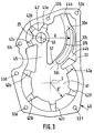
- la figure 2 est une vue en élévation d'un moto-réducteur montrant les pistes d'appui, concentriques à l'arbre de sortie, rapportées sous la plaque de fermeture, selon l'invention et dans laquelle on considère que la plaque de fermeture est transparente;
- la figure 3 est une vue en élévation de la pièce dénommée joint-butée dans laquelle s'intègre les pistes concentriques d'appui.
- Figure 1 is a schematic sectional view showing a gear motor provided with a closure plate according to the invention;
- Figure 2 is an elevational view of a gear motor showing the support tracks, concentric with the output shaft, reported under the closure plate, according to the invention and in which it is considered that the closure plate is transparent;
- Figure 3 is an elevational view of the part called joint-stop in which integrates the concentric support tracks.
Sur les figures 1 et 2, on a représenté un moto-réducteur, notamment pour l'entraînement d'un système d'essuyage, comprenant un moteur électrique 1 et un carter creux 2 muni d'une plaque de fermeture 3. Ce carter contient un système de réduction constitué d'une roue dentée 4 mobile en rotation autour d'un axe 5 et entraînée par une vis sans fin 6 issue du rotor du moteur électrique 1.In FIGS. 1 and 2, a geared motor is shown, in particular for driving a wiping system, comprising an electric motor 1 and a
La roue 4 porte un pion 7, parallèle à l'axe 5 et sensiblement excentré par rapport à celui-ci, monté libre en rotation dans un logement 8 de la roue 4.The
Le pion 7 est relié à un système bielle-manivelle 9 qui permet de transformer le mouvement de rotation de ladite roue 4 en mouvement de rotation alternatif à un arbre de sortie 10. Ledit arbre de sortie 10 est logé dans un fût 11 situé au fond du carter 2 en reposant sur un palier 12.The pin 7 is connected to a connecting rod-
Le système bielle-manivelle 9 est composé d'un bras 13 formant bielle, relié à l'une 14 de ses extrémités au pion 7 en laissant dépasser, au delà de sa face externe 15, un tronçon d'extrémité 16 du pion 7, et présentant à l'autre extrémité un secteur denté 17. Ce secteur denté s'engrène en 19 avec un autre secteur denté 18, lié de manière fixe à l'arbre de sortie 10.The connecting rod-
Les deux secteurs dentés 17 et 18 sont maintenus constamment en prise grâce à deux balanciers 20a et 20b, situés de part et d'autre des faces longitudinales desdits secteurs dentés, en formant une manivelle et en permettant de relier rigidement le bras 13 et l'arbre de sortie 10. Ces deux balanciers sont maintenus ensembles, d'une part par l'intermédiaire d'une ouverture 22a (pour le balancier 20a) et 22b (pour le balancier 20b) prévue à une extrémité desdits balanciers et qui vient entourer l'extrémité 23 de l'arbre de sortie 10, et d'autre part par un pivot 21, libre en rotation, disposé à l'autre extrémité desdits balanciers.The two
Les deux balanciers ont ainsi un mouvement de rotation autour de l'arbre de sortie 10.The two pendulums thus have a rotational movement around the
En variante non représentée, le système bielle-manivelle est composé d'un premier bras relié, à une extrémité au pion porté par la roue denté, et à l'autre extrémité à un deuxième bras par l'intermédiaire d'un axe de pivotement, ce deuxième bras étant lui-même relié à l'arbre de sortie.In a variant not shown, the rod-crank system is composed of a first arm connected, at one end to the pin carried by the toothed wheel, and at the other end to a second arm via a pivot axis , this second arm being itself connected to the output shaft.
Comme mieux visible sur la figure 1, le pivot 21 comporte deux diamètres différents, un premier diamètre, dans sa partie centrale, sensiblement inférieur à celui de l'alésage 25 du bras 13 de manière à ce que le pivot vienne s'insérer avec un jeu minime dans ledit bras 13, et un second diamètres, à ses deux extrémités, sensiblement inférieur à celui des alésages 24a et 24b des deux balanciers.As best seen in Figure 1, the
En relation avec la figure 1, le pivot 21 a une dimension axiale supérieure à l'épaisseur réunie des deux balanciers 20a, 20b et du bras 13 de manière à dégager deux extrémités 26a et 26b qui dépassent de part et d'autre des balanciers. Ces extrémités sont écrasées pour former deux rivetages, que l'on désignera aussi par 26a et 26b, qui maintiennent axialement les deux balanciers 20a, 20b autour de l'arbre 13.In relation to FIG. 1, the
En considérant la figure 1, le carter 2 est fermé à sa partie supérieure par une plaque de fermeture 3, généralement réalisée à partir d'une feuille métallique de faible épaisseur, et reliée aux bords dudit carter par tous moyens connus tel que serrage par vis ou rivetage.Considering FIG. 1, the
Cette plaque de fermeture présente, sur sa face interne, une surépaisseur 27a, 27b entourant le rivetage 26a et formant deux pistes concentriques à l'arbre de sortie 37a et 37b comme mieux visible sur la figure 2.This closure plate has, on its internal face, an
Cette surépaisseur 27a, 27b, est dans l'exemple représenté, en un matériaux plastique à faible coefficient de frottement et est rapportée, en appui, de manière fixe sur ladite plaque de fermeture.This
Il est en outre prévu que les pistes concentriques 37a et 37b soient d'une épaisseur telle que cette surépaisseur 27a, 27b soit en contact avec la surface supérieure du balancier 20a comme mieux visible sur la figure 1.It is further provided that the
Les pistes concentriques 37a et 37b forment une fente de guidage en arc de cercle et grâce à la composition et à la forme de cette fente en arc de cercle 37a, 37b, le rivetage 26a, dépassant de la surface du balancier 20a, peut glisser dans ladite fente de guidage. Pour cette raison, le rayon R du cercle servant de support à l'arc de cercle formant ladite fente de guidage 37a, 37b correspond à la distance entre l'axe 29 de l'arbre de sortie 10 et l'axe 28 du pivot 21.The
Ainsi, les balanciers 20a, 20b, sont guidés dans leur mouvement de rotation autour de l'arbre 10 par le rivetage 26a glissant entre les pistes concentriques 37a et 37b. De plus, le contact de la surépaisseur 27a, 27b avec les balanciers 20a, 20b évite l'arc-boutement desdits balanciers lorsque le bras 13 formant bielle transmet le mouvement de rotation audits balanciers. Les pistes concentriques d'appui 37a et 37b permettent ainsi de supprimer les efforts axiaux, dus par exemple à une mauvaise position de travail, qui cumulés avec les efforts radiaux, détériorent la liaison entre le pivot 21 et le bras formant bielle 13.Thus, the
En outre, les deux extrémités 30a et 30b de la fente en arc de cercle 37a, 37b peuvent servir de butées de fin de course pour le sertissage 26a de manière à limiter les à-coups aux moments des changements de sens de l'engrènement.In addition, the two
Dans l'exemple présenté sur la figure 1, la face interne de la plaque de fermeture 3 présente, en plus de la surépaisseur 27a, 27b, deux surépaisseurs 31 et 32.In the example presented in FIG. 1, the internal face of the
Ces surépaisseurs sont parties intégrantes d'une pièce 40 comprenant un joint 33 placé entre le bord du carter 2 et le bord de la plaque de fermeture 3.These extra thicknesses are an integral part of a
A la figure 3, on a représenté un mode de réalisation de la pièce 40, que nous désignerons par joint-butée, comprenant un joint 33, à la périphérie de ladite pièce 40, une plaquette plane 41 de forme circulaire, une rondelle 42 et la fente de guidage en arc de cercle 37a, 37b.In FIG. 3, an embodiment of the
Ce joint-butée 40 est en un matériau à faible coefficient de frottement et il est prévu qu'il soit positionné en appui sur la plaque de fermeture 3, le joint 33 étant situé entre le bord supérieur 50 du carter 2 et le bord 51 de la plaque de fermeture 3 comme mieux visible sur la figure 1.This
Ce joint 33 a une forme calquée sur celle du bord supérieur 50 du carter 2, en se référant à la figure 2, et à des perçages 52a-52f situés sur ledit bord supérieur 50 correspondent des perçages 53a-53f du joint 33 (visibles à la figure 3), ces perçages servant à relier ensemble le carter 2 et la plaque de fermeture 3, au moyen de vis ou de rivets par exemple.This
Le joint 33 se glisse ainsi exactement à la jointure de la plaque de fermeture 3 et du carter 2 et il assure une liaison étanche de ces deux éléments. Il empêche en effet de la graisse ou des poussières de pénétrer à l'intérieur du carter.The
En relation avec la figure 3, la plaquette 41 présente une forme périphérique circulaire dont le rayon R' est au moins égal au rayon r considéré entre l'axe 5 de rotation de la roue 4 et l'axe du pion 7 (visible à la figure 2), de préférence R' est égal au rayon r augmenté du rayon du pion 7. Ladite plaquette est placée coaxialement avec l'axe 5 et en appui sur la plaque de fermeture 3.In relation to FIG. 3, the
Ainsi lors du montage et du vissage de la plaque de fermeture 3 sur le bord 50 du carter, il est prévu que la face externe 54, dirigée vers le carter 2, de la plaquette 41 vienne porter à glissement sur la surface supérieure située à l'extrémité 16 du pion 7.Thus during assembly and screwing of the
Grâce à la composition et à la forme circulaire de la plaquette 41, la surface de l'extrémité 16 du pion 7 peut glisser facilement tout au long du mouvement circulaire du pion 7 autour de l'axe 5 alors que le pion 7, et donc également l'extrémité 14 du bras formant bielle 13, est calé en direction axiale.Thanks to the composition and the circular shape of the
En se référant à la figure 3, la rondelle évidée 42 présente un alésage 55 de diamètre sensiblement supérieur au diamètre de l'extrémité 23 de l'arbre de sortie 10. Elle est disposée coaxialement avec l'axe 29 de l'arbre de sortie 10 de manière à venir entourer l'extrémité 23 en prenant appui, sur le balancier 20a d'une part, et sur la plaque de fermeture d'autre part, lorsque cette dernière est mise en place sur le carter 2, comme mieux visible sur la figure 1.Referring to Figure 3, the
Bien entendu, il est prévu un espace entre la surface terminale 56 de l'extrémité 23 de l'arbre de sortie et la surface interne, celle dirigée vers l'intérieur du carter 2, de la plaque de fermeture 3, lorsque cette dernière est mise en place sur ledit carter. La surépaisseur 32 sera prévue pour être d'une épaisseur suffisante pour que l'extrémité 23 de l'arbre 10 ne vienne pas en contact avec la face interne de la plaque de fermeture 3.Of course, a space is provided between the
Ainsi, l'arbre de sortie 10 est immobilisé en translation axiale grâce à la surépaisseur 32, mais aussi tous mouvements radiaux de la portion d'arbre 10 située au delà du palier 12 sont empêchés par la disposition de l'extrémité 23 dans l'alésage 55 de la rondelle 42 servant dans ce cas de palier radial.Thus, the
Le joint-butée 40 permet donc d'avoir une pièce unique assurant les fonctions:
- d'étanchéité à la graisse et à la poussière de la
liaison carter 2/plaque de fermeture 3 grâce au joint 33, - d'appui et de maintien radial au niveau de l'arbre de sortie 10 grâce à la rondelle 42,
- d'appui et de frottement du
bras formant bielle 13 au niveau de la roue 4 grâce à la plaquette 41, - et d'appui et de guidage de l'extrémité du balancier formant manivelle pour éviter son arc-boutement grâce à la fente en arc de cercle 37a, 37b.
- grease and dust tightness of the
casing 2 /closing plate 3 connection thanks to thegasket 33, - radial support and maintenance at the
output shaft 10 thanks to thewasher 42, - of support and friction of the connecting
rod arm 13 at the level of thewheel 4 thanks to theplate 41, - and for supporting and guiding the end of the balance forming a crank to avoid its bracing thanks to the slot in a
circular arc
Les liaisons, comme la liaison entre le pivot 21 et le bras formant bielle 13, la liaison entre le pion 7 et la roue 4 et la liaison entre l'arbre d'axe 5 portant la roue 4 et ladite roue, s'en trouvent améliorées ainsi que l'engrènement entre les secteurs dentés 17 et 18.The connections, such as the connection between the
En pratique, et comme cela est visible sur la figure 3, la fente en arc de cercle 37a, 37b est reliée au joint 33 par des languettes 44a et 44b, la plaquette 41 est reliée au joint 33 par une pluralité de languettes 42a-42e et la rondelle 42 est reliée au joint 33 par des languettes 43a-43c. De plus la fente en arc de cercle 37a, 37b est reliée à la plaquette 41 en une jonction 57 et un bras 45 relie entre elles la rondelle 42 et la plaquette 41. Ainsi, le joint-butée 40 est une pièce monobloc pouvant être par exemple moulée.In practice, and as can be seen in FIG. 3, the slot in a
Bien entendu, il est possible de ne pas relier ensembles dans une même pièce les éléments: fente en arc de cercle 37a, 37b, plaquette 41, rondelle 42 et joint 33, par exemple en fixant directement l'un ou plus de ces éléments directement sur la face interne de la plaque de fermeture 3 au moyen de picots ou par tout autre moyen connu.Of course, it is possible not to connect the elements together in the same part: slot in a
D'autre part, dans le cas où la plaque de fermeture 3 est réalisée en matière plastique, il est prévu que cette matière soit à faible coefficient de frottement de manière à élaborer, conjointement avec la plaque de fermeture, les surépaisseurs 27a, 27b de la fente en arc de cercle 37a, 37b et/ou la surépaisseur 31 de la plaquette 41 et/ou la surépaisseur 32 de la rondelle 42 en réalisant une seule pièce dans la même matière.On the other hand, in the case where the
On a décrit ici l'invention dans le cas d'un moto-réducteur où l'embiellage est formé par un bras formant bielle muni d'un secteur denté s'engrenant dans un autre secteur denté mais elle peut naturellement s'appliquer à tout type de moteur avec un mécanisme bielle-manivelle incorporé.The invention has been described here in the case of a geared motor where the linkage is formed by an arm forming a connecting rod provided with a toothed sector meshing with another toothed sector but it can naturally be applied to any type of motor with a rod-crank mechanism incorporated.
Claims (10)
Applications Claiming Priority (2)
| Application Number | Priority Date | Filing Date | Title |
|---|---|---|---|
| FR9406978 | 1994-06-06 | ||
| FR9406978A FR2720706B1 (en) | 1994-06-06 | 1994-06-06 | Geared motor comprising a hollow casing provided with a closing plate, in particular wiping geared motor. |
Publications (2)
| Publication Number | Publication Date |
|---|---|
| EP0686536A1 true EP0686536A1 (en) | 1995-12-13 |
| EP0686536B1 EP0686536B1 (en) | 1998-07-22 |
Family
ID=9463978
Family Applications (1)
| Application Number | Title | Priority Date | Filing Date |
|---|---|---|---|
| EP95108246A Expired - Lifetime EP0686536B1 (en) | 1994-06-06 | 1995-05-30 | A motorized reduction gear unit having a hollow casing with a cover plate, especially for a vehicle screen wiper drive unit |
Country Status (5)
| Country | Link |
|---|---|
| US (1) | US5622077A (en) |
| EP (1) | EP0686536B1 (en) |
| DE (1) | DE69503573T2 (en) |
| ES (1) | ES2120665T3 (en) |
| FR (1) | FR2720706B1 (en) |
Families Citing this family (13)
| Publication number | Priority date | Publication date | Assignee | Title |
|---|---|---|---|---|
| DE69506322T2 (en) * | 1994-09-29 | 1999-05-06 | Valeo Systemes Dessuyage | Geared motor with a hollow housing provided with a sealing cover, in particular a wiper geared motor |
| JP3180018B2 (en) * | 1996-02-16 | 2001-06-25 | アスモ株式会社 | Motor device |
| JP3607400B2 (en) * | 1996-02-19 | 2005-01-05 | アスモ株式会社 | Motor equipment |
| US5983439A (en) * | 1998-04-30 | 1999-11-16 | Trico Products Corporation | Windshield wiper assembly having a variable speed drive mechanism |
| DE19947620A1 (en) * | 1999-10-04 | 2001-04-05 | Valeo Auto Electric Gmbh | Vehicle windscreen wiping device, with press joint connecting transmission driven shaft to crank |
| DE10242304A1 (en) * | 2002-09-12 | 2004-03-25 | Robert Bosch Gmbh | Windscreen wiper system is driven by gearwheel which cooperates with worm, gearwheel having rib on one side which connects with stud on drive housing to lock wipers in their starting position |
| JP4508799B2 (en) * | 2004-09-21 | 2010-07-21 | 株式会社ミツバ | Wiper motor |
| JP4495559B2 (en) * | 2004-09-21 | 2010-07-07 | 株式会社ミツバ | Wiper motor |
| DE102006042322A1 (en) * | 2006-09-08 | 2008-03-27 | Robert Bosch Gmbh | Windscreen wiper system with a windshield wiper drive, in particular for a rear window wiper of a motor vehicle with a modular interchangeable gear assembly |
| EP2881623A1 (en) * | 2013-12-05 | 2015-06-10 | Continental Automotive GmbH | Actuator |
| JP6632904B2 (en) * | 2016-02-08 | 2020-01-22 | 株式会社エンプラス | Gear device and method of assembling gear device |
| US10935123B2 (en) * | 2016-12-22 | 2021-03-02 | Siemens Aktiengesellschaft | Angle geared motor |
| US10760675B1 (en) * | 2019-06-05 | 2020-09-01 | American Axle & Manufacturing, Inc. | Assembly with gasket configured to partly form lubricant delivery channel |
Citations (3)
| Publication number | Priority date | Publication date | Assignee | Title |
|---|---|---|---|---|
| FR2552723A1 (en) * | 1983-10-03 | 1985-04-05 | Bosch Gmbh Robert | Gearing for windscreen wiper drive |
| EP0479673A1 (en) * | 1990-10-05 | 1992-04-08 | Valeo Systemes D'essuyage | Geared motor with its housing closure cover, especially for a windscreenwiper |
| EP0498949A1 (en) * | 1991-02-14 | 1992-08-19 | ITT Automotive Europe GmbH | Driving device, especially for a windscreen wiper system on a motor vehicle |
Family Cites Families (10)
| Publication number | Priority date | Publication date | Assignee | Title |
|---|---|---|---|---|
| FR479673A (en) * | 1915-09-04 | 1916-04-27 | Eugene Ropp | Showcase |
| DE498949C (en) * | 1928-09-28 | 1930-05-26 | Leopold Spira | Paint atomizer |
| US2237919A (en) * | 1938-11-03 | 1941-04-08 | Apex Electrical Mfg Co | Agitator drive mechanism |
| US2357152A (en) * | 1941-04-02 | 1944-08-29 | Stewart Warner Corp | Electric windshield wiper |
| US2861457A (en) * | 1954-06-07 | 1958-11-25 | Gen Motors Corp | Windshield wiper actuating mechanism |
| US4885953A (en) * | 1984-07-02 | 1989-12-12 | Cummins Engine Company, Inc. | Gear train housing of an engine |
| US4918363A (en) * | 1988-09-30 | 1990-04-17 | Venture Mfg. Co. | Actuator for TVRO parabolic antenna |
| DE3916945C2 (en) * | 1989-05-24 | 1999-08-05 | Teves Gmbh Alfred | Pendulum gear, in particular for windshield wipers on motor vehicles |
| DE3920731C2 (en) * | 1989-06-24 | 1999-09-02 | Teves Gmbh Alfred | Drive device, in particular for a windshield wiper system on a motor vehicle |
| FR2699758B1 (en) * | 1992-12-17 | 1995-02-03 | Valeo Systemes Dessuyage | Drive unit for a motor vehicle wiper. |
-
1994
- 1994-06-06 FR FR9406978A patent/FR2720706B1/en not_active Expired - Fee Related
-
1995
- 1995-05-30 DE DE69503573T patent/DE69503573T2/en not_active Expired - Fee Related
- 1995-05-30 EP EP95108246A patent/EP0686536B1/en not_active Expired - Lifetime
- 1995-05-30 ES ES95108246T patent/ES2120665T3/en not_active Expired - Lifetime
- 1995-06-05 US US08/462,846 patent/US5622077A/en not_active Expired - Lifetime
Patent Citations (4)
| Publication number | Priority date | Publication date | Assignee | Title |
|---|---|---|---|---|
| FR2552723A1 (en) * | 1983-10-03 | 1985-04-05 | Bosch Gmbh Robert | Gearing for windscreen wiper drive |
| EP0479673A1 (en) * | 1990-10-05 | 1992-04-08 | Valeo Systemes D'essuyage | Geared motor with its housing closure cover, especially for a windscreenwiper |
| FR2667670A1 (en) | 1990-10-05 | 1992-04-10 | Valeo Systemes Dessuyage | MOTOR REDUCER PROVIDED WITH A COVER FOR CLOSING THE HOUSING OF THE MOTOR REDUCER, ESPECIALLY MOTOR REDUCER OF WIPING. |
| EP0498949A1 (en) * | 1991-02-14 | 1992-08-19 | ITT Automotive Europe GmbH | Driving device, especially for a windscreen wiper system on a motor vehicle |
Also Published As
| Publication number | Publication date |
|---|---|
| US5622077A (en) | 1997-04-22 |
| DE69503573D1 (en) | 1998-08-27 |
| FR2720706A1 (en) | 1995-12-08 |
| DE69503573T2 (en) | 1999-02-11 |
| FR2720706B1 (en) | 1996-07-26 |
| ES2120665T3 (en) | 1998-11-01 |
| EP0686536B1 (en) | 1998-07-22 |
Similar Documents
| Publication | Publication Date | Title |
|---|---|---|
| CA2234436C (en) | Device for closing and locking the blockers of a thrust reverser | |
| EP0686536B1 (en) | A motorized reduction gear unit having a hollow casing with a cover plate, especially for a vehicle screen wiper drive unit | |
| EP0686537B1 (en) | Geared motor having a hollow housing equipped with a closure plate, especially a geared motor for a wiping system | |
| EP2073228B1 (en) | Compact control for medium- and high-voltage electric devices | |
| FR2508090A1 (en) | WIRE DRIVING DEVICE FOR MEANS FOR WINDOW ADJUSTMENT | |
| FR2698060A1 (en) | Wiper device for wiping a window carried by an opening panel of a motor vehicle. | |
| EP0479673B1 (en) | Geared motor with its housing closure cover, especially for a windscreenwiper | |
| FR2801652A1 (en) | ADJUSTABLE REINFORCEMENT FOR A PIVOT MOVEMENT SYSTEM OF A FIRST HINGE PIECE IN RELATION TO A SECOND HINGE PIECE | |
| EP0603085B1 (en) | Windscreen wiper with rotation damper, especially for motorvehicles | |
| EP0685374A1 (en) | Geared motor, especially for the windscreen wiper assembly of a vehicle | |
| FR2720707A1 (en) | Motor and reduction gear unit esp. for windscreen wiper | |
| FR2611837A1 (en) | Device for actuating a clutch with control | |
| FR2610259A1 (en) | DEVICE FOR CONTROLLING A COUPLING MEANS SUCH AS FOR EXAMPLE A CLUTCH | |
| EP0711689B1 (en) | Geared motor having a hollow housing equipped with a closure plate, especially for a vehicle windscreen wiper device | |
| EP0467750B1 (en) | Driving arm mounting arrangement, in particular for windshield wiper | |
| FR2720991A1 (en) | Wiper for rear windows of vehicle with double opening doors | |
| FR2462303A1 (en) | DEVICE HAVING TWO ELECTRIC MOTORS FOR ORIENTING EXTERIOR MIRRORS OF MOTOR VEHICLES | |
| EP0519141B1 (en) | Hinge with integral stop for vehicle doors or other closure members | |
| EP0072278A1 (en) | Double ball-joint device | |
| EP0568462B1 (en) | Window washing device, in particular for the glazed surfaces of a motor vehicle | |
| EP0534835B1 (en) | Seal, in particular for pump shafts | |
| FR3023766A1 (en) | GEAR PADING SYSTEM FOR A WIPER MOTOREDUCER | |
| EP2073227B1 (en) | Compact and robust control for medium- and high-voltage electric devices | |
| FR2737445A1 (en) | Flow regulator for controlling temperature in air conditioned motor vehicle - has two drive motors with separate transmissions, with nearer control vane and transmission having passage for shaft driving second control vane | |
| FR3096634A1 (en) | Drum brake actuator gear motor, including a reduction rate of 30 A 210 |
Legal Events
| Date | Code | Title | Description |
|---|---|---|---|
| PUAI | Public reference made under article 153(3) epc to a published international application that has entered the european phase |
Free format text: ORIGINAL CODE: 0009012 |
|
| AK | Designated contracting states |
Kind code of ref document: A1 Designated state(s): DE ES GB IT |
|
| 17P | Request for examination filed |
Effective date: 19960531 |
|
| 17Q | First examination report despatched |
Effective date: 19970411 |
|
| GRAG | Despatch of communication of intention to grant |
Free format text: ORIGINAL CODE: EPIDOS AGRA |
|
| GRAG | Despatch of communication of intention to grant |
Free format text: ORIGINAL CODE: EPIDOS AGRA |
|
| GRAH | Despatch of communication of intention to grant a patent |
Free format text: ORIGINAL CODE: EPIDOS IGRA |
|
| GRAH | Despatch of communication of intention to grant a patent |
Free format text: ORIGINAL CODE: EPIDOS IGRA |
|
| GRAA | (expected) grant |
Free format text: ORIGINAL CODE: 0009210 |
|
| AK | Designated contracting states |
Kind code of ref document: B1 Designated state(s): DE ES GB IT |
|
| GBT | Gb: translation of ep patent filed (gb section 77(6)(a)/1977) |
Effective date: 19980723 |
|
| REF | Corresponds to: |
Ref document number: 69503573 Country of ref document: DE Date of ref document: 19980827 |
|
| REG | Reference to a national code |
Ref country code: ES Ref legal event code: FG2A Ref document number: 2120665 Country of ref document: ES Kind code of ref document: T3 |
|
| PLBE | No opposition filed within time limit |
Free format text: ORIGINAL CODE: 0009261 |
|
| STAA | Information on the status of an ep patent application or granted ep patent |
Free format text: STATUS: NO OPPOSITION FILED WITHIN TIME LIMIT |
|
| 26N | No opposition filed | ||
| REG | Reference to a national code |
Ref country code: GB Ref legal event code: IF02 |
|
| PGFP | Annual fee paid to national office [announced via postgrant information from national office to epo] |
Ref country code: ES Payment date: 20080522 Year of fee payment: 14 Ref country code: DE Payment date: 20080514 Year of fee payment: 14 |
|
| PGFP | Annual fee paid to national office [announced via postgrant information from national office to epo] |
Ref country code: IT Payment date: 20080520 Year of fee payment: 14 |
|
| PGFP | Annual fee paid to national office [announced via postgrant information from national office to epo] |
Ref country code: GB Payment date: 20080506 Year of fee payment: 14 |
|
| GBPC | Gb: european patent ceased through non-payment of renewal fee |
Effective date: 20090530 |
|
| PG25 | Lapsed in a contracting state [announced via postgrant information from national office to epo] |
Ref country code: GB Free format text: LAPSE BECAUSE OF NON-PAYMENT OF DUE FEES Effective date: 20090530 |
|
| PG25 | Lapsed in a contracting state [announced via postgrant information from national office to epo] |
Ref country code: DE Free format text: LAPSE BECAUSE OF NON-PAYMENT OF DUE FEES Effective date: 20091201 |
|
| REG | Reference to a national code |
Ref country code: ES Ref legal event code: FD2A Effective date: 20090601 |
|
| PG25 | Lapsed in a contracting state [announced via postgrant information from national office to epo] |
Ref country code: ES Free format text: LAPSE BECAUSE OF NON-PAYMENT OF DUE FEES Effective date: 20090601 |
|
| PG25 | Lapsed in a contracting state [announced via postgrant information from national office to epo] |
Ref country code: IT Free format text: LAPSE BECAUSE OF NON-PAYMENT OF DUE FEES Effective date: 20090530 |