EP2072939A1 - Fin tube type heat exchanger - Google Patents
Fin tube type heat exchanger Download PDFInfo
- Publication number
- EP2072939A1 EP2072939A1 EP07828734A EP07828734A EP2072939A1 EP 2072939 A1 EP2072939 A1 EP 2072939A1 EP 07828734 A EP07828734 A EP 07828734A EP 07828734 A EP07828734 A EP 07828734A EP 2072939 A1 EP2072939 A1 EP 2072939A1
- Authority
- EP
- European Patent Office
- Prior art keywords
- heat
- cut
- transfer
- parts
- transfer tubes
- Prior art date
- Legal status (The legal status is an assumption and is not a legal conclusion. Google has not performed a legal analysis and makes no representation as to the accuracy of the status listed.)
- Withdrawn
Links
Images




Classifications
-
- F—MECHANICAL ENGINEERING; LIGHTING; HEATING; WEAPONS; BLASTING
- F28—HEAT EXCHANGE IN GENERAL
- F28F—DETAILS OF HEAT-EXCHANGE AND HEAT-TRANSFER APPARATUS, OF GENERAL APPLICATION
- F28F1/00—Tubular elements; Assemblies of tubular elements
- F28F1/10—Tubular elements and assemblies thereof with means for increasing heat-transfer area, e.g. with fins, with projections, with recesses
- F28F1/12—Tubular elements and assemblies thereof with means for increasing heat-transfer area, e.g. with fins, with projections, with recesses the means being only outside the tubular element
- F28F1/24—Tubular elements and assemblies thereof with means for increasing heat-transfer area, e.g. with fins, with projections, with recesses the means being only outside the tubular element and extending transversely
- F28F1/32—Tubular elements and assemblies thereof with means for increasing heat-transfer area, e.g. with fins, with projections, with recesses the means being only outside the tubular element and extending transversely the means having portions engaging further tubular elements
- F28F1/325—Fins with openings
-
- F—MECHANICAL ENGINEERING; LIGHTING; HEATING; WEAPONS; BLASTING
- F28—HEAT EXCHANGE IN GENERAL
- F28F—DETAILS OF HEAT-EXCHANGE AND HEAT-TRANSFER APPARATUS, OF GENERAL APPLICATION
- F28F1/00—Tubular elements; Assemblies of tubular elements
- F28F1/10—Tubular elements and assemblies thereof with means for increasing heat-transfer area, e.g. with fins, with projections, with recesses
-
- F—MECHANICAL ENGINEERING; LIGHTING; HEATING; WEAPONS; BLASTING
- F28—HEAT EXCHANGE IN GENERAL
- F28F—DETAILS OF HEAT-EXCHANGE AND HEAT-TRANSFER APPARATUS, OF GENERAL APPLICATION
- F28F1/00—Tubular elements; Assemblies of tubular elements
- F28F1/10—Tubular elements and assemblies thereof with means for increasing heat-transfer area, e.g. with fins, with projections, with recesses
- F28F1/12—Tubular elements and assemblies thereof with means for increasing heat-transfer area, e.g. with fins, with projections, with recesses the means being only outside the tubular element
- F28F1/24—Tubular elements and assemblies thereof with means for increasing heat-transfer area, e.g. with fins, with projections, with recesses the means being only outside the tubular element and extending transversely
- F28F1/32—Tubular elements and assemblies thereof with means for increasing heat-transfer area, e.g. with fins, with projections, with recesses the means being only outside the tubular element and extending transversely the means having portions engaging further tubular elements
-
- F—MECHANICAL ENGINEERING; LIGHTING; HEATING; WEAPONS; BLASTING
- F28—HEAT EXCHANGE IN GENERAL
- F28F—DETAILS OF HEAT-EXCHANGE AND HEAT-TRANSFER APPARATUS, OF GENERAL APPLICATION
- F28F13/00—Arrangements for modifying heat-transfer, e.g. increasing, decreasing
- F28F13/06—Arrangements for modifying heat-transfer, e.g. increasing, decreasing by affecting the pattern of flow of the heat-exchange media
-
- F—MECHANICAL ENGINEERING; LIGHTING; HEATING; WEAPONS; BLASTING
- F28—HEAT EXCHANGE IN GENERAL
- F28F—DETAILS OF HEAT-EXCHANGE AND HEAT-TRANSFER APPARATUS, OF GENERAL APPLICATION
- F28F17/00—Removing ice or water from heat-exchange apparatus
- F28F17/005—Means for draining condensates from heat exchangers, e.g. from evaporators
Definitions
- the present invention relates to a finned tube heat exchanger, and particularly to a finned tube heat exchanger provided with heat-transfer fins disposed along an airflow, and a plurality of heat-transfer tubes inserted into the heat-transfer fins and arranged in a direction substantially orthogonal to the direction of airflow.
- a finned tube heat exchanger i.e., cross fin-and-tube heat exchanger
- heat-transfer fins disposed along an airflow
- a plurality of heat-transfer tubes inserted into the heat-transfer fins and arranged in a direction substantially orthogonal to the direction of airflow.
- a method using cut-and-raised machining is sometimes adopted in a finned tube heat exchanger for enhancing heat transfer by forming parts that are cut, raised up, and opened toward the upstream side of the airflow direction in positions of the heat-transfer fin surfaces on the two sides of the heat-transfer tubes, for the purpose of renewing the boundary layers on the heat-transfer fins and reducing the dead water regions formed in parts of the heat-transfer fins downstream of the heat-transfer tubes in the airflow direction (see Patent Document 1).
- drain water condensed water and other water droplets
- An object of the present invention is to provide a finned tube heat exchanger having both a heat transfer enhancing effect produced by the cut-and-raised parts and drainage efficiency.
- the finned tube heat exchanger according to a first aspect is provided with heat-transfer fins and a plurality of heat-transfer tubes.
- the heat-transfer fins are disposed along an airflow.
- the plurality of heat-transfer tubes is inserted into the heat-transfer fins and arranged in a direction substantially orthogonal to the airflow direction.
- a plurality of cut-and-raised parts is formed in the heat-transfer fins by cut-and-raise machining, the parts being straightly aligned from the upstream side toward the downstream side in the airflow direction on two sides, as viewed in a perpendicular direction, of the heat-transfer tubes.
- Imaginary straight lines that connect the plurality of cut-and-raised parts are sloped relative to the airflow direction so that the airflow in the vicinity of the heat-transfer tubes is guided to the rearward side of the heat-transfer tubes in the airflow direction.
- Concavities are formed in the heat-transfer fins about the periphery of the heat-transfer tubes at least in a part below a horizontal plane that passes through a center axis of the heat-transfer tubes.
- a plurality of cut-and-raised parts is divided from the upstream side toward the downstream side in the airflow direction.
- the plurality of cut-and-raised parts is disposed in the forward area in the airflow direction so that air in the vicinity of the heat-transfer tubes is guided to the rearward side of the heat-transfer tubes in the airflow direction.
- the cut-and-raised parts are not provided in a portion of the heat-transfer fins toward the lower part of the heat-transfer tubes. Concavities are formed at least in the lower part of the periphery of the heat-transfer tubes in the heat-transfer fins.
- an effect can be obtained in which the boundary layers are renewed by the cut-and-raised parts.
- An effect can also be obtained in which the dead water regions formed in the portions of the heat-transfer fins disposed rearward in the airflow direction are reduced. Drain water can be made less liable to be trapped between the heat-transfer tubes and the cut-and-raised parts. Drain water generated on the surface of the heat-transfer fins can furthermore be made to be more readily removed from the gaps between the cut-and-raised parts. Drain water is temporarily trapped in the concavities, and is then made to flow downward and be removed after a predetermined amount or more of the drain water has accumulated. Consequently, a heat transfer enhancing effect produced by the cut-and-raised parts can be obtained without being affected by drain water generated on the surface of the heat-transfer fins.
- the finned tube heat exchanger according to a second aspect is the finned tube heat exchanger according to the first aspect, wherein concavities are formed in the heat-transfer fins about the entire periphery of the heat-transfer tubes.
- concavities are formed in the heat-transfer fins about the entire periphery of the heat-transfer tubes. Therefore, drain water is temporarily trapped in the concavities, and is then made to flow downward and be removed after a predetermined amount or more of the drain water has accumulated. Accordingly, the drain water can be removed without being trapped between the heat-transfer tubes and the cut-and-raised parts. A heat transfer enhancing effect can be obtained thereby.
- the finned tube heat exchanger according to a third aspect is the finned tube heat exchanger according to the first or second aspect, wherein the heat-transfer fins are shaped as waffles having folds formed in a direction substantially orthogonal to the airflow direction.
- the heat-transfer fins are shaped as waffles having folds formed in a direction substantially orthogonal to the airflow direction.
- the finned tube heat exchanger according to a fourth aspect is the finned tube heat exchanger according to the first or second aspect, wherein the concavities have lower end parts and upper end parts.
- the lower end parts and the upper end parts have a protruding shape.
- a first point on the lower parts of the concavities is set to be a vertex of the lower end parts.
- a second point at the upper parts of the concavities is set to be a vertex of the upper end parts.
- the concavities are shaped so that a protruding shape is given to the lower end parts whose vertices are set to be the first points in the lower parts of the concavities, and to the upper end parts whose vertices are set to be the second points in the upper parts of the concavities. Therefore, generated drain water can be more readily removed from the concavities. Accordingly, drain water generated in the heat exchanger can be made to flow smoothly downward.
- the finned tube heat exchanger according to a fifth aspect is the finned tube heat exchanger according to the first or second aspect, wherein the concavities have lower end parts whose vertices are set to be first points on the lower parts thereof.
- the concavities are also shaped so that a protruding shape is given to the lower end parts.
- the concavities are shaped so that a protruding shape is given to the lower end parts whose vertices are set to be the first points in the lower parts of the concavities. Therefore, generated drain water can be more readily removed from the concavities. Accordingly, the drain water generated in the heat exchanger can be made to flow smoothly downward.
- the finned tube heat exchanger according to a sixth aspect is the finned tube heat exchanger according to the third aspect, wherein the folds are shaped at least as concave folds.
- the concavities have lower end parts whose vertices are set to be first points on the lower parts thereof.
- the concavities are shaped so that a protruding shape is given to the lower end parts, and are formed so that there is a match between the lower end parts and the concave folds.
- the concavities are formed so that the downward protruding lower end parts are superimposed on the concave folds. Therefore, the generated drain water can be more readily removed from the concavities. Accordingly, drain water generated in the heat exchanger can be made to flow smoothly downward.
- the finned tube heat exchanger according to a seventh aspect is the finned tube heat exchanger according to the sixth aspect, wherein the cut-and-raised parts are formed in a region that excludes the region directly below the heat-transfer tubes.
- drain water generated in the heat exchanger can be made to flow smoothly downward.
- the finned tube heat exchanger according to an eighth aspect is the finned tube heat exchanger according to the sixth or seventh aspect, wherein the plurality of cut-and-raised parts includes a plurality of first cut-and-raised parts and a plurality of second cut-and-raised parts.
- the plurality of first cut-and-raised parts is formed below the heat-transfer tubes.
- the plurality of second cut-and-raised parts is formed above the heat-transfer tubes.
- a first imaginary straight line that connects the plurality of first cut-and-raised parts is sloped in relation to the third straight line that passes through the center axis of the heat-transfer tubes and is parallel to the airflow direction, so that the downstream side in the airflow direction is farther away than the upstream side from the third straight line.
- a second imaginary straight line that connects the plurality of second cut-and-raised parts is sloped in relation to the third straight line so that the downstream side in the airflow direction is closer than the upstream side to the third straight line.
- the first cut-and-raised parts formed below the heat-transfer tubes are sloped in relation to the third straight line that passes through the center axis of the heat-transfer tubes and is parallel to the airflow direction, so that the downstream side in the airflow direction is farther away than the upstream side from the third straight line.
- the first cut-and-raised parts formed below the heat-transfer tubes where drain water is readily trapped are arranged in a sloped manner so that there is a match between the airflow direction and the direction in which drain water flows and falls downward.
- the drain water when drain water has been generated, the drain water can be readily removed without being trapped between the heat-transfer tubes and the cut-and-raised parts. Accordingly, the water drainage performance of the heat-transfer fins can be improved and the heat transfer effect can be enhanced.
- an effect can be obtained in which the boundary layers are renewed by the cut-and-raised parts.
- An effect can also be obtained in which the dead water regions formed in the portions of the area rearward of the heat-transfer fins in the airflow direction are reduced. Drain water can be made less liable to be trapped between the heat-transfer tubes and the cut-and-raised parts. Drain water generated on the surface of the heat-transfer fins can furthermore be more readily removed from the gaps between the cut-and-raised parts. Drain water is temporarily trapped in the concavities, and is then made to flow downward and be removed after a predetermined amount or more of the drain water has accumulated. Consequently, a heat transfer enhancing effect produced by the cut-and-raised parts can be obtained without being affected by drain water generated on the surface of heat-transfer fins.
- drain water is temporarily trapped in the concavities, and is then made to flow downward and be removed after a predetermined amount or more of the drain water has accumulated. Accordingly, the drain water can be removed without being trapped between the heat-transfer tubes and the cut-and-raised parts. A heat transfer enhancing effect can be obtained thereby.
- heat exchange between the heat-transfer fins and air can be enhanced. Drain water can be more readily brought to the folds and made to flow downward. Accordingly, a heat transfer enhancing effect produced by the cut-and-raised parts can be obtained without being affected by drain water generated on the surface of the heat-transfer fins.
- the generated drain water can be more readily removed from the concavities. Accordingly, drain water generated in the heat exchanger can be made to flow smoothly downward.
- the generated drain water can be more readily removed from the concavities. Accordingly, drain water generated in the heat exchanger can be made to flow smoothly downward.
- the generated drain water can be more readily removed from the concavities. Accordingly, drain water generated in the heat exchanger can be made to flow smoothly downward.
- the generated drain water can be more readily removed from the concavities. Accordingly, drain water generated in the heat exchanger can be made to flow smoothly downward.
- the drain water when drain water has been generated, the drain water can be readily removed without being trapped between the heat-transfer tubes and the cut-and-raised parts. Accordingly, the water drainage performance of the heat-transfer fins can be improved and the heat transfer effect can be enhanced.
- FIGS. 1 to 3 show the main part of the finned tube heat exchanger 1 according to an embodiment of the present invention.
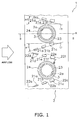
- FIG. 1 is a cross-sectional view of the finned tube heat exchanger 1.
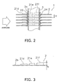
- FIG. 2 is a cross-sectional view along the line II-II of FIG. 1 .
- FIG. 3 is a cross-sectional view along the line III-III of FIG. 1 .
- the finned tube heat exchanger 1 is a cross fin-and-tube heat exchanger, and is mainly composed of a plurality of plate-shaped heat-transfer fins 2 and a plurality of heat-transfer tubes 3.
- the heat-transfer fins 2 are aligned and disposed in the plate thickness direction in a state in which the plane direction of the fins is made to substantially match the airflow direction of air or the like.
- a plurality of through-holes 2a is formed in the heat-transfer fins 2 at intervals in the direction substantially orthogonal to the airflow direction.
- the peripheral portion of the through-holes 2a is an annular collar part 23 that protrudes to one side in the plate thickness direction of the heat-transfer fins 2.
- the collar part 23 makes contact with the surface opposite from the surface on which the collar part 23 of the heat-transfer fins 2 adjacent in the plate thickness direction is formed, and a predetermined interval H is maintained between each heat-transfer fin 2 in the plate thickness direction.
- the heat-transfer tubes 3 are tube members through which a refrigerant or another heating medium flows inside, are inserted into the plurality of heat-transfer fins 2 aligned and disposed in the plate thickness direction, and are arranged in a direction substantially orthogonal to the airflow direction. Specifically, the heat-transfer tubes 3 are passed via the through-holes 2a formed in the heat-transfer fins 2 and are brought into close contact with the inside surface of the collar part 23 by expanding the tube during assembly of the finned tube heat exchanger 1.
- the finned tube heat exchanger 1 of the present embodiment is used in a state in which the plurality of heat-transfer tubes 3 is arranged so as to be aligned substantially in the vertical direction. Accordingly, the airflow moves crosswise to the finned tube heat exchanger 1, substantially toward the horizontal direction.
- the terms "upper side,” “upper,” “lower side,” and “lower” refer to the arrangement direction of the heat-transfer tubes 3.
- a plurality (three on each lower and upper side in the present embodiment)of cut-and-raised parts 21a to 21f formed in the surfaces of the heat-transfer fins 2b by the cut-and-raise machining is disposed on the heat-transfer fins 2, the cut-and-raised parts being straightly aligned from the upstream side toward the downstream side in the airflow direction on two sides of the heat-transfer tubes 3 in a perpendicular direction(i.e., lower and upper side of each heat-transfer tube 3).
- the lower cut-and-raised parts are first cut-and-raised parts 21 a to 2 1 c
- the upper cut-and-raised parts are second cut-and-raised parts 21d to 21f.
- a first imaginary straight line L1 that connects the first cut-and-raised parts 21a to 21c, and a second imaginary straight line L2 that connects the second cut-and-raised parts 21d to 21f are sloped relative to the airflow direction so that the airflow in the vicinity of the heat-transfer tubes 3 is guided rearward of the heat-transfer tubes 3 in the airflow direction.
- the angles of attack ⁇ 1, ⁇ 2 of the first straight line L1 and the second straight line L2 with respect to the airflow direction are set so as to be in the range of 10° to 30°.
- the first cut-and-raised parts 21a to 21c and the second cut-and-raised parts 21 d to 21 f are thus sloped with respect to the airflow direction so that the airflow in the vicinity of the heat-transfer tubes 3 is guided rearward of the heat-transfer tubes 3 in the airflow direction. Accordingly, an effect of renewing the boundary layers can be reliably obtained mainly by the first cut-and-raised part 21a and the second cut-and-raised part 21d disposed in the forward area of the heat-transfer fins 2 in the airflow direction, among the cut-and-raised parts 21a to 21f.
- each of the cut-and-raised parts 21a to 21f is formed so that the height increases gradually toward the downstream side in the airflow direction.
- each of the cut-and-raised parts 21a to 21f are substantially trapezoidal or substantially triangular in shape (see FIG. 3; FIG. 3 is a diagram showing the second cut-and-raised parts 21d to 21f, but the first cut-and-raised parts 21a to 21c have the same shape), and the maximum height h is formed so as to be lower than the height H of the collar part 23.
- Each of the cut-and-raised parts 21a to 21f formed in the two sides of the heat-transfer tubes 3 is thus divided into a plurality (three in each upper and lower side in the present embodiment) of first cut-and-raised parts 21 a to 21c and second cut-and-raised parts 21d to 21f in sequence from upstream to downstream in the airflow direction. Accordingly, drain water generated on the heat-transfer fins 2 can be more readily removed from the gaps in the first cut-and-raised parts 21a to 21 c and the gaps in the second cut-and-raised parts 21d to 21f. A heat transfer enhancing effect produced by the cut-and-raised parts 21a to 21f can thereby be obtained without being affected by drain water generated on the heat-transfer fins 2.
- Slits 22a to 22f formed in the heat-transfer fins 2 when the cut-and-raised parts 21a to 21f are cut and raised are arranged above the cut-and-raised parts 21a to 21f respectively.
- Concentrically shaped concavities 24 that are concentric with the collar part 23 are provided at the periphery of the collar part 23 in the heat-transfer fins 2.
- the concavities 24 are formed by concaving the heat-transfer fins 2 in the direction opposite from the collar part 23 in a position in which the cross-section circumscribes the collar part 23 in the manner shown in FIG. 2 .
- the cut-and-raised parts 21a to 21f are thus formed by cutting and raising the heat-transfer fins 2 from the top toward the bottom. Accordingly, first slits 22a to 22c are formed between the heat-transfer tubes 3 and the first cut-and-raised parts 21 a to 21c where drain water is particularly readily trapped, and the drain water is less likely to be trapped between the heat-transfer tubes 3 and the first cut-and-raised parts 21a to 21c. For this reason, drain water is more readily removed from the heat-transfer fins 2. Also, the concavities 24 are formed in the entire periphery of the heat-transfer tubes 3 in the heat-transfer fins 2.
- drain water is temporarily trapped in the concavities 24 and then made to flow and be removed after a predetermined amount or more of the drain water has accumulated. Accordingly, drain water can be removed without being trapped between the heat-transfer tubes 3 and the first cut-and-raised parts 21a to 21 c.
- the first cut-and-raised parts 21a to 21c and the second cut-and-raised parts 21d to 21f are straightly aligned on the first straight line L1 and the second straight line L2 from the upstream side of the airflow to the downstream side, whereby the first cut-and-raised part 21c, which is disposed on the heat-transfer fins 2 downstream in the airflow direction has the same slope as the first cut-and-raised part 21a disposed on the upstream side of the airflow direction, and the second cut-and-raised part 21f has the same slope as the second cut-and-raised part 21d disposed on the upstream side of the airflow direction, among the cut-and-raised parts 21a to 21f.
- a heat transfer enhancing effect produced by the cut-and-raised parts 21a to 21f can be obtained without being affected by drain water generated on the heat-transfer fins 2, and since it is also possible to prevent the formation to new dead water zones behind the first cut-and-raised part 2 1 c and the second cut-and-raised part 21f, the cut-and-raised parts 21a to 21f provide a heat transfer enhancing effect and better drainage characteristics.
- the cut-and-raised parts 21a to 21f are shaped so that the height gradually increases toward the downstream side in the airflow direction, whereby longitudinal vortices can be generated behind the cut-and-raised parts 21 a to 21f. Therefore, the cut-and-raised parts 21a to 21f can further improve heat transfer enhancing effect.
- the finned tube heat exchanger according to the present invention allows drain water to be more readily removed, can effectively provide a heat transfer effect, and can be used as a finned tube heat exchanger, and particularly as a finned tube heat exchanger provided with heat-transfer fins disposed along an airflow, and a plurality of heat-transfer tubes inserted into the heat-transfer fins and arranged in a direction substantially orthogonal to the direction of airflow.
Landscapes
- Engineering & Computer Science (AREA)
- Physics & Mathematics (AREA)
- Thermal Sciences (AREA)
- Mechanical Engineering (AREA)
- General Engineering & Computer Science (AREA)
- Geometry (AREA)
- Heat-Exchange Devices With Radiators And Conduit Assemblies (AREA)
Abstract
Description
- The present invention relates to a finned tube heat exchanger, and particularly to a finned tube heat exchanger provided with heat-transfer fins disposed along an airflow, and a plurality of heat-transfer tubes inserted into the heat-transfer fins and arranged in a direction substantially orthogonal to the direction of airflow.
- Often used in a conventional air conditioning apparatus or the like is a finned tube heat exchanger (i.e., cross fin-and-tube heat exchanger) provided with heat-transfer fins disposed along an airflow, and a plurality of heat-transfer tubes inserted into the heat-transfer fins and arranged in a direction substantially orthogonal to the direction of airflow. Therefore, a method using cut-and-raised machining is sometimes adopted in a finned tube heat exchanger for enhancing heat transfer by forming parts that are cut, raised up, and opened toward the upstream side of the airflow direction in positions of the heat-transfer fin surfaces on the two sides of the heat-transfer tubes, for the purpose of renewing the boundary layers on the heat-transfer fins and reducing the dead water regions formed in parts of the heat-transfer fins downstream of the heat-transfer tubes in the airflow direction (see Patent Document 1).
- Japanese Laid-open Patent Application No.
61-110889 - When a finned tube heat exchanger that employs cut-and-raised parts as described above is used as an evaporator having refrigerant or another heating medium in which air is used as a heat source typified by an air conditioning apparatus or the like, there is a problem in that condensed water and other water droplets (hereinafter referred to as "drain water") generated by heat exchange between air and the heating medium are trapped in the cut-and-raised parts and cause ventilation resistance to increase.
- An object of the present invention is to provide a finned tube heat exchanger having both a heat transfer enhancing effect produced by the cut-and-raised parts and drainage efficiency.
- The finned tube heat exchanger according to a first aspect is provided with heat-transfer fins and a plurality of heat-transfer tubes. The heat-transfer fins are disposed along an airflow. The plurality of heat-transfer tubes is inserted into the heat-transfer fins and arranged in a direction substantially orthogonal to the airflow direction. A plurality of cut-and-raised parts is formed in the heat-transfer fins by cut-and-raise machining, the parts being straightly aligned from the upstream side toward the downstream side in the airflow direction on two sides, as viewed in a perpendicular direction, of the heat-transfer tubes. Imaginary straight lines that connect the plurality of cut-and-raised parts are sloped relative to the airflow direction so that the airflow in the vicinity of the heat-transfer tubes is guided to the rearward side of the heat-transfer tubes in the airflow direction. Concavities are formed in the heat-transfer fins about the periphery of the heat-transfer tubes at least in a part below a horizontal plane that passes through a center axis of the heat-transfer tubes.
- In the finned tube heat exchanger, a plurality of cut-and-raised parts is divided from the upstream side toward the downstream side in the airflow direction. The plurality of cut-and-raised parts is disposed in the forward area in the airflow direction so that air in the vicinity of the heat-transfer tubes is guided to the rearward side of the heat-transfer tubes in the airflow direction. The cut-and-raised parts are not provided in a portion of the heat-transfer fins toward the lower part of the heat-transfer tubes. Concavities are formed at least in the lower part of the periphery of the heat-transfer tubes in the heat-transfer fins.
- Therefore, an effect can be obtained in which the boundary layers are renewed by the cut-and-raised parts. An effect can also be obtained in which the dead water regions formed in the portions of the heat-transfer fins disposed rearward in the airflow direction are reduced. Drain water can be made less liable to be trapped between the heat-transfer tubes and the cut-and-raised parts. Drain water generated on the surface of the heat-transfer fins can furthermore be made to be more readily removed from the gaps between the cut-and-raised parts. Drain water is temporarily trapped in the concavities, and is then made to flow downward and be removed after a predetermined amount or more of the drain water has accumulated. Consequently, a heat transfer enhancing effect produced by the cut-and-raised parts can be obtained without being affected by drain water generated on the surface of the heat-transfer fins.
- The finned tube heat exchanger according to a second aspect is the finned tube heat exchanger according to the first aspect, wherein concavities are formed in the heat-transfer fins about the entire periphery of the heat-transfer tubes.
- In the present invention, concavities are formed in the heat-transfer fins about the entire periphery of the heat-transfer tubes. Therefore, drain water is temporarily trapped in the concavities, and is then made to flow downward and be removed after a predetermined amount or more of the drain water has accumulated. Accordingly, the drain water can be removed without being trapped between the heat-transfer tubes and the cut-and-raised parts. A heat transfer enhancing effect can be obtained thereby.
- The finned tube heat exchanger according to a third aspect is the finned tube heat exchanger according to the first or second aspect, wherein the heat-transfer fins are shaped as waffles having folds formed in a direction substantially orthogonal to the airflow direction.
- In the present invention, the heat-transfer fins are shaped as waffles having folds formed in a direction substantially orthogonal to the airflow direction.
- Therefore, heat exchange between the heat-transfer fins and air can be enhanced. Drain water can be more readily brought to the folds and made to flow downward. Accordingly, a heat transfer enhancing effect produced by the cut-and-raised parts can be obtained without being affected by drain water generated on the surface of the heat-transfer fins.
- The finned tube heat exchanger according to a fourth aspect is the finned tube heat exchanger according to the first or second aspect, wherein the concavities have lower end parts and upper end parts. The lower end parts and the upper end parts have a protruding shape. In this case, a first point on the lower parts of the concavities is set to be a vertex of the lower end parts. A second point at the upper parts of the concavities is set to be a vertex of the upper end parts.
- In the present invention, the concavities are shaped so that a protruding shape is given to the lower end parts whose vertices are set to be the first points in the lower parts of the concavities, and to the upper end parts whose vertices are set to be the second points in the upper parts of the concavities. Therefore, generated drain water can be more readily removed from the concavities. Accordingly, drain water generated in the heat exchanger can be made to flow smoothly downward.
- The finned tube heat exchanger according to a fifth aspect is the finned tube heat exchanger according to the first or second aspect, wherein the concavities have lower end parts whose vertices are set to be first points on the lower parts thereof. The concavities are also shaped so that a protruding shape is given to the lower end parts.
- In the present invention, the concavities are shaped so that a protruding shape is given to the lower end parts whose vertices are set to be the first points in the lower parts of the concavities. Therefore, generated drain water can be more readily removed from the concavities. Accordingly, the drain water generated in the heat exchanger can be made to flow smoothly downward.
- The finned tube heat exchanger according to a sixth aspect is the finned tube heat exchanger according to the third aspect, wherein the folds are shaped at least as concave folds. The concavities have lower end parts whose vertices are set to be first points on the lower parts thereof. The concavities are shaped so that a protruding shape is given to the lower end parts, and are formed so that there is a match between the lower end parts and the concave folds.
- In the present invention, the concavities are formed so that the downward protruding lower end parts are superimposed on the concave folds. Therefore, the generated drain water can be more readily removed from the concavities. Accordingly, drain water generated in the heat exchanger can be made to flow smoothly downward.
- The finned tube heat exchanger according to a seventh aspect is the finned tube heat exchanger according to the sixth aspect, wherein the cut-and-raised parts are formed in a region that excludes the region directly below the heat-transfer tubes.
- Therefore, the generated drain water can be more readily removed from the concavities. Accordingly, drain water generated in the heat exchanger can be made to flow smoothly downward.
- The finned tube heat exchanger according to an eighth aspect is the finned tube heat exchanger according to the sixth or seventh aspect, wherein the plurality of cut-and-raised parts includes a plurality of first cut-and-raised parts and a plurality of second cut-and-raised parts. The plurality of first cut-and-raised parts is formed below the heat-transfer tubes. The plurality of second cut-and-raised parts is formed above the heat-transfer tubes. A first imaginary straight line that connects the plurality of first cut-and-raised parts is sloped in relation to the third straight line that passes through the center axis of the heat-transfer tubes and is parallel to the airflow direction, so that the downstream side in the airflow direction is farther away than the upstream side from the third straight line. A second imaginary straight line that connects the plurality of second cut-and-raised parts is sloped in relation to the third straight line so that the downstream side in the airflow direction is closer than the upstream side to the third straight line.
- In the present invention, the first cut-and-raised parts formed below the heat-transfer tubes are sloped in relation to the third straight line that passes through the center axis of the heat-transfer tubes and is parallel to the airflow direction, so that the downstream side in the airflow direction is farther away than the upstream side from the third straight line. In other words, the first cut-and-raised parts formed below the heat-transfer tubes where drain water is readily trapped are arranged in a sloped manner so that there is a match between the airflow direction and the direction in which drain water flows and falls downward.
- Therefore, when drain water has been generated, the drain water can be readily removed without being trapped between the heat-transfer tubes and the cut-and-raised parts. Accordingly, the water drainage performance of the heat-transfer fins can be improved and the heat transfer effect can be enhanced.
- In the finned tube heat exchanger according to the first aspect, an effect can be obtained in which the boundary layers are renewed by the cut-and-raised parts. An effect can also be obtained in which the dead water regions formed in the portions of the area rearward of the heat-transfer fins in the airflow direction are reduced. Drain water can be made less liable to be trapped between the heat-transfer tubes and the cut-and-raised parts. Drain water generated on the surface of the heat-transfer fins can furthermore be more readily removed from the gaps between the cut-and-raised parts. Drain water is temporarily trapped in the concavities, and is then made to flow downward and be removed after a predetermined amount or more of the drain water has accumulated. Consequently, a heat transfer enhancing effect produced by the cut-and-raised parts can be obtained without being affected by drain water generated on the surface of heat-transfer fins.
- In the finned tube heat exchanger according to the second aspect, drain water is temporarily trapped in the concavities, and is then made to flow downward and be removed after a predetermined amount or more of the drain water has accumulated. Accordingly, the drain water can be removed without being trapped between the heat-transfer tubes and the cut-and-raised parts. A heat transfer enhancing effect can be obtained thereby.
- In the finned tube heat exchanger according to the third aspect, heat exchange between the heat-transfer fins and air can be enhanced. Drain water can be more readily brought to the folds and made to flow downward. Accordingly, a heat transfer enhancing effect produced by the cut-and-raised parts can be obtained without being affected by drain water generated on the surface of the heat-transfer fins.
- In the finned tube heat exchanger according to the fourth aspect, the generated drain water can be more readily removed from the concavities. Accordingly, drain water generated in the heat exchanger can be made to flow smoothly downward.
- In the finned tube heat exchanger according to the fifth aspect, the generated drain water can be more readily removed from the concavities. Accordingly, drain water generated in the heat exchanger can be made to flow smoothly downward.
- In the finned tube heat exchanger according to the sixth aspect, the generated drain water can be more readily removed from the concavities. Accordingly, drain water generated in the heat exchanger can be made to flow smoothly downward.
- In the finned tube heat exchanger according to the seventh aspect, the generated drain water can be more readily removed from the concavities. Accordingly, drain water generated in the heat exchanger can be made to flow smoothly downward.
- In the finned tube heat exchanger according to the eighth aspect, when drain water has been generated, the drain water can be readily removed without being trapped between the heat-transfer tubes and the cut-and-raised parts. Accordingly, the water drainage performance of the heat-transfer fins can be improved and the heat transfer effect can be enhanced.
-
-
FIG. 1 is a cross-sectional view of a finned tube heat exchanger according to an embodiment of the present invention. -
FIG. 2 is a cross-sectional view along the line II-II ofFIG. 1 . -
FIG. 3 is a cross-sectional view along the line III-III ofFIG. 1 . -
FIG. 4 is a cross-sectional view of the finned tube heat exchanger according to modified example (1). -
FIG. 5 is a cross-sectional view of the finned tube heat exchanger according to modified example (2). -
FIG. 6 is a cross-sectional view of the finned tube heat exchanger according to modified example (2). -
FIG. 7 is a cross-sectional view of the finned tube heat exchanger according to modified example (3). -
FIG. 8 is a cross-sectional view of the finned tube heat exchanger according to modified example (4). -
FIG. 9 is a cross-sectional view along the line IX-IX ofFIG. 8 . -
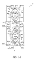
FIG. 10 is a cross-sectional view of the finned tube heat exchanger according to modified example (5). -
FIG. 11 is a cross-sectional view of the finned tube heat exchanger according to modified example (5). -
FIG. 12 is a cross-sectional view of the finned tube heat exchanger according to modified example (6). -
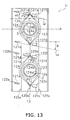
FIG. 13 is a cross-sectional view of the finned tube heat exchanger according to modified example (7). -
- 1 to 1i i
- finned tube heat exchanger
- 2, 4 to 12
- heat-transfer fins
- 3
- heat-transfer tube
- 24, 44, 54, 64, 74, 84, 94, 104, 114, 124
- concavity
- 21 a to 21c c
- first cut-and-raised part
- 21 d to 21f
- second cut-and-raised part
- 41 a to 41c c
- first cut-and-raised part
- 41 d to 41f
- second cut-and-raised part
- 51a, 51b
- first cut-and-raised part
- 51 d to 51f
- second cut-and-raised part
- 61 a, 61 c
- first cut-and-raised part
- 61 d to 61f
- second cut-and-raised part
- 71a to 71 c
- first cut-and-raised part
- 71 d to 71 f
- second cut-and-raised part
- 81a to 81 c
- first cut-and-raised part
- 81 d to 81 f
- second cut-and-raised part
- 85a to 85c
- fold
- 94a, 104a, 114a, 124a
- lower end part
- 94b, 124b
- upper end part
- 95a to 95c
- fold
- 105a to 105c
- fold
- 115a to 115c
- fold
- 125a to 125c
- fold
- 91 a to 91 c
- first cut-and-raised part
- 91 d to 91f
- second cut-and-raised part
- 101a to 101c
- first cut-and-raised part
- 101d to 101f
- second cut-and-raised part
- 111a first
- cut-and-raised part
- 111b to 111d
- second cut-and-raised part
- 121a, 121b
- first cut-and-raised part
- 121c to 121e
- second cut-and-raised part
- L1
- first straight line
- L2
- second straight line
- L3
- third straight line
- L4
- fourth straight line
- P1
- first point
- P2
- second point
- Embodiments of the finned tube heat exchanger according to the present invention will be described below with reference to the drawings.
-
FIGS. 1 to 3 show the main part of the finnedtube heat exchanger 1 according to an embodiment of the present invention. Here,FIG. 1 is a cross-sectional view of the finnedtube heat exchanger 1.FIG. 2 is a cross-sectional view along the line II-II ofFIG. 1 .FIG. 3 is a cross-sectional view along the line III-III ofFIG. 1 . - The finned
tube heat exchanger 1 is a cross fin-and-tube heat exchanger, and is mainly composed of a plurality of plate-shaped heat-transfer fins 2 and a plurality of heat-transfer tubes 3. The heat-transfer fins 2 are aligned and disposed in the plate thickness direction in a state in which the plane direction of the fins is made to substantially match the airflow direction of air or the like. A plurality of through-holes 2a is formed in the heat-transfer fins 2 at intervals in the direction substantially orthogonal to the airflow direction. The peripheral portion of the through-holes 2a is anannular collar part 23 that protrudes to one side in the plate thickness direction of the heat-transfer fins 2. Thecollar part 23 makes contact with the surface opposite from the surface on which thecollar part 23 of the heat-transfer fins 2 adjacent in the plate thickness direction is formed, and a predetermined interval H is maintained between each heat-transfer fin 2 in the plate thickness direction. The heat-transfer tubes 3 are tube members through which a refrigerant or another heating medium flows inside, are inserted into the plurality of heat-transfer fins 2 aligned and disposed in the plate thickness direction, and are arranged in a direction substantially orthogonal to the airflow direction. Specifically, the heat-transfer tubes 3 are passed via the through-holes 2a formed in the heat-transfer fins 2 and are brought into close contact with the inside surface of thecollar part 23 by expanding the tube during assembly of the finnedtube heat exchanger 1. - The finned
tube heat exchanger 1 of the present embodiment is used in a state in which the plurality of heat-transfer tubes 3 is arranged so as to be aligned substantially in the vertical direction. Accordingly, the airflow moves crosswise to the finnedtube heat exchanger 1, substantially toward the horizontal direction. In the following description, the terms "upper side," "upper," "lower side," and "lower" refer to the arrangement direction of the heat-transfer tubes 3. - Next, the specific shape of the heat-
transfer fins 2 used in the finnedtube heat exchanger 1 of the finned tube heat exchanger according to the present embodiment will be described. - A plurality (three on each lower and upper side in the present embodiment)of cut-and-raised
parts 21a to 21f formed in the surfaces of the heat-transfer fins 2b by the cut-and-raise machining is disposed on the heat-transfer fins 2, the cut-and-raised parts being straightly aligned from the upstream side toward the downstream side in the airflow direction on two sides of the heat-transfer tubes 3 in a perpendicular direction(i.e., lower and upper side of each heat-transfer tube 3). Here, the lower cut-and-raised parts are first cut-and-raisedparts 21 a to 2 1 c, and the upper cut-and-raised parts are second cut-and-raisedparts 21d to 21f. A first imaginary straight line L1 that connects the first cut-and-raisedparts 21a to 21c, and a second imaginary straight line L2 that connects the second cut-and-raisedparts 21d to 21f are sloped relative to the airflow direction so that the airflow in the vicinity of the heat-transfer tubes 3 is guided rearward of the heat-transfer tubes 3 in the airflow direction. Here, the angles of attack α1, α2 of the first straight line L1 and the second straight line L2 with respect to the airflow direction are set so as to be in the range of 10° to 30°. - In this manner, the first cut-and-raised
parts 21a to 21c and the second cut-and-raisedparts 21 d to 21 f are thus sloped with respect to the airflow direction so that the airflow in the vicinity of the heat-transfer tubes 3 is guided rearward of the heat-transfer tubes 3 in the airflow direction. Accordingly, an effect of renewing the boundary layers can be reliably obtained mainly by the first cut-and-raisedpart 21a and the second cut-and-raisedpart 21d disposed in the forward area of the heat-transfer fins 2 in the airflow direction, among the cut-and-raisedparts 21a to 21f. An effect is also obtained in which the dead water regions formed in the portions of the area rearward of the heat-transfer tubes 3 in the airflow direction are reduced by the first cut-and-raisedpart 21c and the second cut-and-raisedpart 21f disposed in the area rearward of the heat-transfer fins 2 in the airflow direction. - Each of the cut-and-raised
parts 21a to 21f is formed so that the height increases gradually toward the downstream side in the airflow direction. In the present embodiment, each of the cut-and-raisedparts 21a to 21f are substantially trapezoidal or substantially triangular in shape (seeFIG. 3; FIG. 3 is a diagram showing the second cut-and-raisedparts 21d to 21f, but the first cut-and-raisedparts 21a to 21c have the same shape), and the maximum height h is formed so as to be lower than the height H of thecollar part 23. - Each of the cut-and-raised
parts 21a to 21f formed in the two sides of the heat-transfer tubes 3 is thus divided into a plurality (three in each upper and lower side in the present embodiment) of first cut-and-raisedparts 21 a to 21c and second cut-and-raisedparts 21d to 21f in sequence from upstream to downstream in the airflow direction. Accordingly, drain water generated on the heat-transfer fins 2 can be more readily removed from the gaps in the first cut-and-raisedparts 21a to 21 c and the gaps in the second cut-and-raisedparts 21d to 21f. A heat transfer enhancing effect produced by the cut-and-raisedparts 21a to 21f can thereby be obtained without being affected by drain water generated on the heat-transfer fins 2. -
Slits 22a to 22f formed in the heat-transfer fins 2 when the cut-and-raisedparts 21a to 21f are cut and raised are arranged above the cut-and-raisedparts 21a to 21f respectively. Concentrically shapedconcavities 24 that are concentric with thecollar part 23 are provided at the periphery of thecollar part 23 in the heat-transfer fins 2. Theconcavities 24 are formed by concaving the heat-transfer fins 2 in the direction opposite from thecollar part 23 in a position in which the cross-section circumscribes thecollar part 23 in the manner shown inFIG. 2 . - The cut-and-raised
parts 21a to 21f are thus formed by cutting and raising the heat-transfer fins 2 from the top toward the bottom. Accordingly,first slits 22a to 22c are formed between the heat-transfer tubes 3 and the first cut-and-raisedparts 21 a to 21c where drain water is particularly readily trapped, and the drain water is less likely to be trapped between the heat-transfer tubes 3 and the first cut-and-raisedparts 21a to 21c. For this reason, drain water is more readily removed from the heat-transfer fins 2. Also, theconcavities 24 are formed in the entire periphery of the heat-transfer tubes 3 in the heat-transfer fins 2. Therefore, the drain water is temporarily trapped in theconcavities 24 and then made to flow and be removed after a predetermined amount or more of the drain water has accumulated. Accordingly, drain water can be removed without being trapped between the heat-transfer tubes 3 and the first cut-and-raisedparts 21a to 21 c. - The first cut-and-raised
parts 21a to 21c and the second cut-and-raisedparts 21d to 21f are straightly aligned on the first straight line L1 and the second straight line L2 from the upstream side of the airflow to the downstream side, whereby the first cut-and-raisedpart 21c, which is disposed on the heat-transfer fins 2 downstream in the airflow direction has the same slope as the first cut-and-raisedpart 21a disposed on the upstream side of the airflow direction, and the second cut-and-raisedpart 21f has the same slope as the second cut-and-raisedpart 21d disposed on the upstream side of the airflow direction, among the cut-and-raisedparts 21a to 21f. Therefore, not only can dead water regions formed in the area rearward of the heat-transfer tubes 3 in the airflow direction be reduced, but also new dead water regions can be prevented from forming behind the first cut-and-raisedpart 21c and the second cut-and-raisedpart 21f. - As described above, in the finned
tube heat exchanger 1 of the present embodiment, a heat transfer enhancing effect produced by the cut-and-raisedparts 21a to 21f can be obtained without being affected by drain water generated on the heat-transfer fins 2, and since it is also possible to prevent the formation to new dead water zones behind the first cut-and-raisedpart 2 1 c and the second cut-and-raisedpart 21f, the cut-and-raisedparts 21a to 21f provide a heat transfer enhancing effect and better drainage characteristics. - In the finned
tube heat exchanger 1, the cut-and-raisedparts 21a to 21f are shaped so that the height gradually increases toward the downstream side in the airflow direction, whereby longitudinal vortices can be generated behind the cut-and-raisedparts 21 a to 21f. Therefore, the cut-and-raisedparts 21a to 21f can further improve heat transfer enhancing effect. -
- (1) In the present embodiment, all of the first cut-and-raised
parts 21a to 21c on the heat-transfer fins 2 below the heat-transfer tubes 3 are formed by cut-and-raise machining from the top toward the bottom. Drain water is sometimes trapped between the first cut-and-raised parts and the heat-transfer tubes 3. Therefore, all of the first cut-and-raised parts are formed by cut-and-raise machining from the top toward the bottom, whereby trapping of drain water can be minimized.
Consequently,first slits 22a to 22c are formed between the heat-transfer tubes 3 and the first cut-and-raisedparts 21a to 21c, and drain water is not liable to be trapped between the heat-transfer tubes 3 and the first cut-and-raisedparts 21a to 21c. Accordingly, the cut-and-raisedparts 21a to 21f can provide a heat transfer enhancing effect while allowing drain water to be efficiently removed. - (2) In the present invention, the
concavities 24 are formed in the heat-transfer fins 2 around the entire periphery of the heat-transfer tubes 3. Therefore, the drain water is temporarily trapped in theconcavities 24 and then made to flow and be removed after a predetermined amount or more of the drain water has accumulated. Accordingly, drain water can be removed without being trapped between the heat-transfer tubes 3 and the first cut-and-raisedparts 21a to 21c. As a result, an effect can be obtained in which heat transfer is enhanced. -
- (1) All three of the first cut-and-raised
parts 21a to 21c below the heat-transfer tubes 3 in the present embodiment are formed by cutting and raising the heat-transfer fins 2 from the top, but no limitation is imposed thereby, and it is possible to form only the first cut-and-raisedpart 41c in a position most proximate to the heat-transfer tubes 3 by cut-and-raise machining from the top, and the other first cut-and-raisedparts FIG. 4 ). In this case, not only the first cut-and-raisedpart 41c, but also the first cut-and-raisedpart 41b may be formed by cut-and-raise machining from the top. Thereference numerals FIG. 4 are substituted for 2, 2a in the present embodiment, and the 40s are substituted for 20s (in the present embodiment).
Drain water is most readily trapped between the heat-transfer tubes 3 and the first cut-and-raisedpart 41c in the region (first region R) nearest to the heat-transfer tubes 3. Therefore, the amount of trapped drain water can be minimized by forming the first cut-and-raisedpart 41c of the first region R by cut-and-raise machining from the top toward the bottom.
In the finned tube heat exchanger 1a such as the one shown inFIG. 4 , droplets of drain water are thus less liable to be trapped between the heat-transfer tubes 3 and the first cut-and-raisedpart 41c because at least the first cut-and-raisedpart 41c provided in the position most proximate to the heat-transfer tubes 3 is formed by cut-and-raise machining from the top. Accordingly, drain water can be removed with good efficiency and a heat transfer enhancing effect can be obtained. - (2) In the present embodiment, the first cut-and-raised
parts 21a to 21c below the heat-transfer tubes 3 are formed by cut-and-raise machining from the top of the heat-transfer fins 2, but no limitation is imposed thereby, and it is possible to form cut-and-raised parts by performing cutting and raising from the bottom, as shown inFIG. 5 , so as to achieve vertical symmetry with second cut-and-raised parts 51d to 51f on the upper side with respect to the horizontal plane A that passes through the center of the heat-transfer tubes 3. However, in this case, first cut-and-raisedparts part 51f It is furthermore possible to provide only one first cut-and-raised part so as to leave only the first cut-and-raisedpart 51a furthest from the heat-transfer tubes 3. It is also possible to provide only slits in the manner shown inFIG. 6 in place of providing cut-and-raised parts. In this case, thereference numerals FIG. 5 are substituted for 2,2a in the preset embodiment, and the 50s are substituted for the 20s in the present embodiment. Thereference numerals FIG. 6 are substituted for 2, 2a, and the 60s are substituted for 20s in the present embodiment.
Drain water is most readily trapped between the heat-transfer tubes 3 and the first cut-and-raised part when a first cut-and-raised part is present in the region (first region R) nearest to the heat-transfer tubes 3. In the finnedtube heat exchangers 1b, 1c, a first cut-and-raised part was not provided in the first region R in the heat-transfer fins
Therefore, drain water can be made less likely to be trapped between the heat-transfer tubes 3 and the first cut-and-raised part. Accordingly, the cut-and-raisedparts parts 6 1 a, 61b, 61d to 61f can produce a heat transfer enhancing effect without being affected by drain water generated on the heat-transfer fins - (3) In the present embodiment, the
concavities 24 are formed in the entire periphery of the heat-transfer tubes 3, but no limitation is imposed thereby, andarched concavities 74 may be formed (seeFIG. 7 ) only on the lower part side of the heat-transfer tubes 3 (below the horizontal plane A that passes through the center of the heat-transfer tubes 3). In this case, thereference numerals FIG. 7 are substituted for 2, 2a in the present embodiment, and the 70s are substituted with the 20s in the present embodiment. - (4) In the present embodiment, flat fins are used as the heat-
transfer fins 2, but no limitation is imposed thereby, and waffle-shaped heat-transfer fins 8 (seeFIG 8 ) havingfolds 85a to 85c that are parallel to the perpendicular direction may be used.FIG. 8 is a cross-sectional view of a finnedtube heat exchanger 1e in which waffle-shaped heat-transfer fins 8 have been adopted, andFIG. 9 is a cross-sectional view (excluding the heat-transfer tubes 3) along the line IX-IX ofFIG. 8 . Here, thefolds 85a to 85c shown inFIG. 9 are configured so that thefolds fold 85b is a concave fold.
Since the heat-transfer fins 8 are shaped aswaffles having folds 85a to 85c formed in the direction substantially orthogonal to the airflow direction, an air vortex can be generated and heat transfer between the heat-transfer fins 8 and air can be enhanced. Drain water generated in the vicinity of the heat-transfer tubes 3 can be made to readily flow down along thefold 85b, which is a concave fold. Accordingly, the heat transfer enhancing effect of the cut-and-raisedparts 81a to 81f can be obtained without being affected by the drain water generated on the heat-transfer fins. Thereference numerals - (5) In the present embodiment, the
concavities 24 provided to the heat-transfer fins 2 have a circular shape that is concentric with thecollar part 23, but no limitation is imposed thereby, and also possible are concavities 94 (seeFIG. 10 ) shaped so that thelower end parts 94a and theupper end parts 94b of theconcavities 24 in the heat-transfer fins 2 are made to protrude in a pointed manner, as well as concavities 104 (seeFIG. 11 ) shaped so that only thelower end parts 104a of theconcavities 24 in the heat-transfer fins 2 are made to protrude. The cross-sections of the heat-transfer fins 9 and the heat-transfer fins 10 in the present modified example (5) have the same shape as the cross-section of the heat-transfer fins 8 in modified example (4).
In the present modified example (5), the heat-transfer fins FIGS. 10 and11 are waffle-shaped heat-transfer fins folds 95a to 95c and 105a to 105c that are parallel to the perpendicular direction in the same manner as the heat-transfer fins 8 of modified example (4). In this case, theconcavities 94 having the protrudinglower end parts 94a andupper end parts 94b are formed so that the protrudinglower end parts 94a andupper end parts 94b of theconcavities 94 match thefold 95b, which is a concave fold and which is one of thefolds 95a to 95c of the waffle-shaped heat-transfer fins 9, as shown inFIG. 10 , for example. Here, a first point P1 on the lower part of theconcavities 94 is set to be a vertex of thelower end parts 94a. Also, a second point P2 at the upper part of theconcavities 94 is set to be a vertex of theupper end parts 94b.
Theconcavities 104 in which only thelower end parts 104a protrude are formed so that the protrudinglower end parts 104a of theconcavities 104 match thefold 105b, which is a concave fold and which is one of the folds 105a to 105c of the waffle-shaped heat-transfer fins 10 in the same manner as theconcavities 94 formed in the heat-transfer fins 9 ofFIG. 10 , as shown inFIG. 11 , for example. Here, a first point P1 on the lower part of theconcavities 104 is set to be a vertex of thelower end parts 104a.
In the finned tube heat exchangers 1f, 1g, concavities are thus formed so that the protrudinglower end parts concavities folds folds 95a to 95c and 105a to 105c of the waffle-shaped heat-transfer fins 9, 10 (also superimposed on theupper end parts 94b of theconcavities 94 in the case ofFIG. 10 ). Therefore, drain water generated on the heat-transfer fins concavities
Thereference numerals FIG.10 of the present modified example (5) are substituting for 2, 2a in the present embodiment, and the 90s are substituting for the 20s in the present embodiment. The reference numerals 10, 10a inFIG. 11 of the present modified example (5) are substituting for 2, 2a in the present embodiment, and the 100s are substituting for the 20s in the present embodiment. - (6) The three first cut-and-raised
parts 101a to 101c disposed below the heat-transfer tubes 3 in the finned tube heat exchanger 1g of modified example (5) are formed by cutting and raising the heat-transfer fins 10, but no limitation is imposed thereby, and it is possible to use heat-transfer fins 11 (seeFIG. 12 ) shaped so that a first cut-and-raisedpart 111a is cut and raised in a region that excludes the region directly below the heat-transfer tubes 3. The cross-section of the heat-transfer fins 11 in modified example (6) is the same shape as the cross-section of the heat-transfer fins 8 in modified example (4). The reference numerals 11, 11a inFIG.12 of the present modified example (6) are substituting for 8, 8a in modified example (4), and the 110s are substituting for the 80s in modified example (4). - (7) In the finned tube heat exchanger 1f of the modified example (5), first cut-and-raised
parts 91 a to 91c below the heat-transfer tubes 3 are sloped so that the first cut-and-raisedparts 91c on the downstream side of the airflow direction are closer to the straight line (third straight line L3 inFIG. 13 ) that passes through the center axis of the heat-transfer tubes 3 and is parallel to the airflow direction than the first cut-and-raisedparts 91a on the upstream side, but no limitation is imposed thereby. For example, first cut-and-raisedparts transfer tubes 3 may be formed so that the first cut-and-raisedparts 121b on the downstream side of the airflow direction slope away and are farther away from the third straight line than the first cut-and-raisedparts 121a on the upstream of the airflow direction, in the manner of the heat-transfer fins 12 of the finnedtube heat exchanger 1i ofFIG. 13 . In this case, the first cut-and-raisedparts parts 121c to 121e are arranged. The cross-section of the heat-transfer fins 12 in modified example (7) have the same shape as the cross-section of the heat-transfer fins 8 in modified example (4). The reference numerals 12, 12a inFIG.13 of the present modified example (7) are substituting for 8, 8a in modified example (4), and the 120s are substituting for the 80s in modified example (4). - Embodiments of the present invention were described above with reference to the drawings, but the specific configuration is not limited by these embodiments, and modifications are possible within a scope that does not depart from the spirit of the invention.
- The finned tube heat exchanger according to the present invention allows drain water to be more readily removed, can effectively provide a heat transfer effect, and can be used as a finned tube heat exchanger, and particularly as a finned tube heat exchanger provided with heat-transfer fins disposed along an airflow, and a plurality of heat-transfer tubes inserted into the heat-transfer fins and arranged in a direction substantially orthogonal to the direction of airflow.
Claims (8)
- A finned tube heat exchanger (1 to 1i) comprising:heat-transfer fins (2, 4 to 12) disposed along an airflow;a plurality of heat-transfer tubes (3) inserted into the heat-transfer fins and arranged in a direction substantially orthogonal to the airflow direction, wherein:a plurality of cut-and-raised parts (21a to 21f, 41 a to 41f, 51a, 51b, 51d to 51f, 61a, 61b, 61d to 61f, 71a to 71f, 81a to 81f, 91a to 91f, 101a to 101f, 111a to 111d, 112a to 112e) is formed in the heat-transfer fins by cut-and-raise machining, the parts being straightly aligned from the upstream side toward the downstream side in the airflow direction on two sides, as viewed in a perpendicular direction, of the heat-transfer tubes;imaginary straight lines (L1, L2, L4) that connect the plurality of cut-and-raised parts are sloped relative to the airflow direction so that the airflow in the vicinity of the heat-transfer tubes is guided to the rearward side of the heat-transfer tubes in the airflow direction; andconcavities (24, 44, 54, 64, 74, 84, 94, 104, 114, 124) are formed in the heat-transfer fins on the periphery of the heat-transfer tubes at least in a part below a horizontal plane that passes through a center axis of the heat-transfer tubes.
- The finned tube heat exchanger (1 to 1c, 1e to 1i) according to claim 1, wherein:concavities (24, 44, 54, 64, 84, 94, 104, 114, 124) are formed in the heat-transfer fins about the entire periphery of the heat-transfer tubes.
- The finned tube heat exchanger (1e to 1i) according to claim 1 or 2, wherein:the heat-transfer fins (8 to 12) are shaped as waffles having folds (85a to 85c, 95a to 95c, 105a to 105c, 115a to 115c, 125a to 125c) formed in a direction substantially orthogonal to the airflow direction.
- The finned tube heat exchanger (1f to 1i) according to claim 1 or 2, wherein;
the concavities (94, 124) have lower end parts (94a, 124a) whose vertices are set to be first points (P1) on the lower parts thereof and upper end parts (94b, 124b) pointed at a second point (P2) at the upper parts thereof, and are shaped so that a protruding shape is give to the lower end parts and the upper end parts. - The finned tube heat exchanger (1g, 1h) according to claim 1 or 2, wherein
the concavities (104, 114) have lower end parts (104a, 114a) whose vertices are set to be first points (P1) on the lower parts thereof, and are shaped so that a protruding shape is given to the lower end parts. - The finned tube heat exchanger (1g, 1h) according to claim 3, wherein:the folds (105a, 115a) are shaped as concave folds; and concavities (104, 114) have lower end parts (104a, 114a) whose vertices are set to be first points (P1) on the lower parts thereof, are shaped so that a protruding shape is given to the lower end parts, and are formed so that there is a match between the lower end parts and the concave folds.
- The finned tube heat exchanger (1h) according to claim 6, wherein:the plurality of cut-and-raised parts (111a to 111d) is formed in a region that excludes the region directly below the heat-transfer tubes.
- The finned tube heat exchanger (1i) according to claim 6 or 7, wherein:the plurality of cut-and-raised parts (121a to 121e) includes a plurality of first cut-and-raised parts formed below the heat-transfer tubes and a plurality of second cut-and-raised parts formed above the heat-transfer tubes;a fourth imaginary straight line (L4) that connects the plurality of first cut-and-raised parts is sloped in relation to the third straight line (L3) that passes through the center axis of the heat-transfer tubes and is parallel to the airflow direction, so that the downstream side in the airflow direction is farther away than the upstream side from the third straight line; anda second imaginary straight line (L2) that connects the plurality of second cut-and-raised parts is sloped in relation to the third straight line (L3) so that the downstream side in the airflow direction is closer than the upstream side to the third straight line.
Applications Claiming Priority (3)
| Application Number | Priority Date | Filing Date | Title |
|---|---|---|---|
| JP2006270713 | 2006-10-02 | ||
| JP2007076711A JP4169079B2 (en) | 2006-10-02 | 2007-03-23 | Finned tube heat exchanger |
| PCT/JP2007/068993 WO2008041635A1 (en) | 2006-10-02 | 2007-09-28 | Fin tube type heat exchanger |
Publications (2)
| Publication Number | Publication Date |
|---|---|
| EP2072939A1 true EP2072939A1 (en) | 2009-06-24 |
| EP2072939A4 EP2072939A4 (en) | 2014-05-21 |
Family
ID=39268494
Family Applications (1)
| Application Number | Title | Priority Date | Filing Date |
|---|---|---|---|
| EP07828734.9A Withdrawn EP2072939A4 (en) | 2006-10-02 | 2007-09-28 | HEAT EXCHANGER OF TUBE TYPE WITH FINS |
Country Status (6)
| Country | Link |
|---|---|
| US (1) | US8613307B2 (en) |
| EP (1) | EP2072939A4 (en) |
| JP (1) | JP4169079B2 (en) |
| KR (1) | KR20090075706A (en) |
| AU (1) | AU2007303342B2 (en) |
| WO (1) | WO2008041635A1 (en) |
Cited By (3)
| Publication number | Priority date | Publication date | Assignee | Title |
|---|---|---|---|---|
| CN103857974A (en) * | 2012-04-23 | 2014-06-11 | 松下电器产业株式会社 | Fin tube heat exchanger and method for manufacturing same |
| WO2016075666A1 (en) * | 2014-11-14 | 2016-05-19 | Stefani S.P.A. | Fin for a finned pack for heat exchangers, as well as heat exchanger |
| EP2314973B1 (en) * | 2008-05-27 | 2019-07-10 | Daikin Industries, Ltd. | Fin-tube heat exchanger |
Families Citing this family (16)
| Publication number | Priority date | Publication date | Assignee | Title |
|---|---|---|---|---|
| JP5251237B2 (en) * | 2008-04-30 | 2013-07-31 | ダイキン工業株式会社 | Fin tube type heat exchanger, refrigeration apparatus and hot water supply apparatus provided with the same |
| JP5088236B2 (en) * | 2008-05-27 | 2012-12-05 | ダイキン工業株式会社 | Finned tube heat exchanger |
| JP5266876B2 (en) * | 2008-05-27 | 2013-08-21 | ダイキン工業株式会社 | Finned tube heat exchanger |
| CN102141354B (en) * | 2011-03-25 | 2013-04-24 | 兰州交通大学 | Cambered vortex generator type round tube finned heat exchanger |
| CN102162705B (en) * | 2011-03-25 | 2012-08-15 | 兰州交通大学 | Combined curved-surface vortex generator-type round fin-tube heat exchanger |
| CN103874901B (en) * | 2011-10-14 | 2015-12-23 | 松下电器产业株式会社 | Finned tube heat exchanger |
| JP5974276B2 (en) * | 2012-04-23 | 2016-08-23 | パナソニックIpマネジメント株式会社 | Finned tube heat exchanger |
| WO2017179399A1 (en) * | 2016-04-15 | 2017-10-19 | 三菱電機株式会社 | Heat exchanger |
| WO2019062493A1 (en) * | 2017-09-30 | 2019-04-04 | 杭州三花微通道换热器有限公司 | Heat exchanger and fin |
| WO2019175973A1 (en) * | 2018-03-13 | 2019-09-19 | 日立ジョンソンコントロールズ空調株式会社 | Heat exchanger and air conditioner with same |
| JP2020063883A (en) * | 2018-10-18 | 2020-04-23 | 三星電子株式会社Samsung Electronics Co.,Ltd. | Heat exchanger and air conditioner |
| US11236951B2 (en) * | 2018-12-06 | 2022-02-01 | Johnson Controls Technology Company | Heat exchanger fin surface enhancement |
| WO2022045667A1 (en) * | 2020-08-31 | 2022-03-03 | Samsung Electronics Co., Ltd. | Heat exchanger and air conditioner using the heat exchanger |
| JP7436895B1 (en) * | 2022-08-12 | 2024-02-22 | ダイキン工業株式会社 | Heat exchanger |
| JP7453578B2 (en) * | 2022-08-12 | 2024-03-21 | ダイキン工業株式会社 | Heat exchanger |
| KR20240050865A (en) * | 2022-10-12 | 2024-04-19 | 엘지전자 주식회사 | Heat exchanger |
Family Cites Families (21)
| Publication number | Priority date | Publication date | Assignee | Title |
|---|---|---|---|---|
| US4434844A (en) * | 1981-05-15 | 1984-03-06 | Daikin Kogyo Co., Ltd. | Cross-fin coil type heat exchanger |
| JPS61110889A (en) | 1984-11-05 | 1986-05-29 | Matsushita Electric Ind Co Ltd | Finned heat exchanger |
| JPS62206384A (en) * | 1986-03-05 | 1987-09-10 | Hitachi Ltd | Heat exchanger |
| US4709753A (en) * | 1986-09-08 | 1987-12-01 | Nordyne, Inc. | Uni-directional fin-and-tube heat exchanger |
| DE3737217C3 (en) * | 1987-11-03 | 1994-09-01 | Gea Luftkuehler Happel Gmbh | Heat exchanger tube |
| US4984626A (en) * | 1989-11-24 | 1991-01-15 | Carrier Corporation | Embossed vortex generator enhanced plate fin |
| JP2661356B2 (en) * | 1990-10-22 | 1997-10-08 | 松下電器産業株式会社 | Finned heat exchanger |
| JP2834339B2 (en) * | 1991-02-21 | 1998-12-09 | 松下電器産業株式会社 | Finned heat exchanger |
| JPH0886584A (en) * | 1994-09-20 | 1996-04-02 | Fujitsu General Ltd | Heat exchanger with fins |
| JP3268422B2 (en) * | 1995-09-12 | 2002-03-25 | 株式会社日立製作所 | Fin tube heat exchanger |
| JPH09203593A (en) | 1996-01-30 | 1997-08-05 | Matsushita Electric Ind Co Ltd | Heat exchanger |
| KR100210073B1 (en) | 1996-07-09 | 1999-07-15 | 윤종용 | Heat exchanger of air conditioner |
| US5730214A (en) * | 1997-01-16 | 1998-03-24 | General Motors Corporation | Heat exchanger cooling fin with varying louver angle |
| JPH10332291A (en) | 1997-05-30 | 1998-12-15 | Mitsubishi Heavy Ind Ltd | Fin and tube type heat-exchanger |
| JP3430921B2 (en) | 1997-10-03 | 2003-07-28 | 株式会社日立製作所 | Heat exchanger |
| JP4106779B2 (en) | 1998-12-04 | 2008-06-25 | ダイキン工業株式会社 | Heat transfer fins for heat exchangers for air conditioning |
| CA2391077A1 (en) * | 2001-06-28 | 2002-12-28 | York International Corporation | High-v plate fin for a heat exchanger and a method of manufacturing |
| US7337831B2 (en) * | 2001-08-10 | 2008-03-04 | Yokohama Tlo Company Ltd. | Heat transfer device |
| US6578627B1 (en) * | 2001-12-28 | 2003-06-17 | Industrial Technology Research Institute | Pattern with ribbed vortex generator |
| US6786274B2 (en) * | 2002-09-12 | 2004-09-07 | York International Corporation | Heat exchanger fin having canted lances |
| US7428920B2 (en) * | 2003-08-21 | 2008-09-30 | Visteon Global Technologies, Inc. | Fin for heat exchanger |
-
2007
- 2007-03-23 JP JP2007076711A patent/JP4169079B2/en not_active Expired - Fee Related
- 2007-09-28 AU AU2007303342A patent/AU2007303342B2/en not_active Ceased
- 2007-09-28 EP EP07828734.9A patent/EP2072939A4/en not_active Withdrawn
- 2007-09-28 US US12/442,977 patent/US8613307B2/en not_active Expired - Fee Related
- 2007-09-28 KR KR1020097008507A patent/KR20090075706A/en not_active Ceased
- 2007-09-28 WO PCT/JP2007/068993 patent/WO2008041635A1/en not_active Ceased
Cited By (7)
| Publication number | Priority date | Publication date | Assignee | Title |
|---|---|---|---|---|
| EP2314973B1 (en) * | 2008-05-27 | 2019-07-10 | Daikin Industries, Ltd. | Fin-tube heat exchanger |
| CN103857974A (en) * | 2012-04-23 | 2014-06-11 | 松下电器产业株式会社 | Fin tube heat exchanger and method for manufacturing same |
| EP2843346A4 (en) * | 2012-04-23 | 2015-06-03 | Panasonic Corp | HEAT EXCHANGER WITH FINNED TUBE AND METHOD FOR MANUFACTURING THE SAME |
| CN103857974B (en) * | 2012-04-23 | 2018-03-16 | 松下电器产业株式会社 | Fin-tube heat exchanger and its manufacture method |
| WO2016075666A1 (en) * | 2014-11-14 | 2016-05-19 | Stefani S.P.A. | Fin for a finned pack for heat exchangers, as well as heat exchanger |
| US10948244B2 (en) | 2014-11-14 | 2021-03-16 | Stefani S.P.A. | Fin for a finned pack for heat exchangers, as well as heat exchanger |
| EP3218664B1 (en) * | 2014-11-14 | 2022-06-01 | Stefani S.p.A. | Fin for a finned pack for heat exchangers, as well as heat exchanger |
Also Published As
| Publication number | Publication date |
|---|---|
| JP4169079B2 (en) | 2008-10-22 |
| US20100089557A1 (en) | 2010-04-15 |
| EP2072939A4 (en) | 2014-05-21 |
| AU2007303342A1 (en) | 2008-04-10 |
| AU2007303342B2 (en) | 2010-07-29 |
| WO2008041635A1 (en) | 2008-04-10 |
| JP2008111646A (en) | 2008-05-15 |
| US8613307B2 (en) | 2013-12-24 |
| KR20090075706A (en) | 2009-07-08 |
Similar Documents
| Publication | Publication Date | Title |
|---|---|---|
| AU2007303342B2 (en) | Finned tube heat exchanger | |
| CN102047064B (en) | Heat exchanger | |
| EP2985558B1 (en) | Fin-and-tube heat exchanger and refrigeration cycle device | |
| EP2410266A1 (en) | Drainage structure of corrugated fin-type heat exchanger | |
| EP2048465B1 (en) | Heat exchanger and air conditioner | |
| JP5678392B2 (en) | Corrugated fin heat exchanger drainage structure | |
| US20200011607A1 (en) | Heat exchanger including heat-transfer-tube unit | |
| EP2314973A1 (en) | Fin-tube heat exchanger | |
| JP5958744B2 (en) | Finned tube heat exchanger | |
| US20230003467A1 (en) | Heat exchanger and corrugated fin | |
| JP2022040969A (en) | Heat exchanger and air conditioner using that heat exchanger | |
| EP2843345B1 (en) | Fin-tube heat exchanger and refrigeration cycle device using same | |
| CN101523148A (en) | Fin tube type heat exchanger | |
| JP2010025479A (en) | Heat exchanger | |
| EP1906129A1 (en) | Fin tube heat exchanger | |
| JP2006200788A (en) | Heat exchanger | |
| US20140202670A1 (en) | Stamped thermal expansion relief feature for heat exchangers | |
| JP2010014329A (en) | Heat exchanger | |
| JP2010065892A (en) | Heat exchanger | |
| JP2006207966A (en) | Heat exchanger | |
| JP4940871B2 (en) | Finned tube heat exchanger | |
| JP2008249298A (en) | Finned tube heat exchanger | |
| WO2024224835A1 (en) | Heat exchanger | |
| JPH0674865U (en) | Automotive heat exchanger | |
| JP2013221681A (en) | Fin tube heat exchanger |
Legal Events
| Date | Code | Title | Description |
|---|---|---|---|
| PUAI | Public reference made under article 153(3) epc to a published international application that has entered the european phase |
Free format text: ORIGINAL CODE: 0009012 |
|
| 17P | Request for examination filed |
Effective date: 20090421 |
|
| AK | Designated contracting states |
Kind code of ref document: A1 Designated state(s): AT BE BG CH CY CZ DE DK EE ES FI FR GB GR HU IE IS IT LI LT LU LV MC MT NL PL PT RO SE SI SK TR |
|
| AX | Request for extension of the european patent |
Extension state: AL BA HR MK RS |
|
| DAX | Request for extension of the european patent (deleted) | ||
| A4 | Supplementary search report drawn up and despatched |
Effective date: 20140425 |
|
| RIC1 | Information provided on ipc code assigned before grant |
Ipc: F28F 13/06 20060101ALI20140417BHEP Ipc: F28F 1/32 20060101AFI20140417BHEP Ipc: F28F 17/00 20060101ALI20140417BHEP |
|
| GRAP | Despatch of communication of intention to grant a patent |
Free format text: ORIGINAL CODE: EPIDOSNIGR1 |
|
| INTG | Intention to grant announced |
Effective date: 20170302 |
|
| STAA | Information on the status of an ep patent application or granted ep patent |
Free format text: STATUS: THE APPLICATION IS DEEMED TO BE WITHDRAWN |
|
| 18D | Application deemed to be withdrawn |
Effective date: 20170713 |