EP2072368A1 - Articulation alvéolée notamment pour bielle d'entraînement - Google Patents
Articulation alvéolée notamment pour bielle d'entraînement Download PDFInfo
- Publication number
- EP2072368A1 EP2072368A1 EP08291164A EP08291164A EP2072368A1 EP 2072368 A1 EP2072368 A1 EP 2072368A1 EP 08291164 A EP08291164 A EP 08291164A EP 08291164 A EP08291164 A EP 08291164A EP 2072368 A1 EP2072368 A1 EP 2072368A1
- Authority
- EP
- European Patent Office
- Prior art keywords
- outer tube
- central axis
- articulation according
- articulation
- plane
- Prior art date
- Legal status (The legal status is an assumption and is not a legal conclusion. Google has not performed a legal analysis and makes no representation as to the accuracy of the status listed.)
- Granted
Links
Images
Classifications
-
- B—PERFORMING OPERATIONS; TRANSPORTING
- B61—RAILWAYS
- B61F—RAIL VEHICLE SUSPENSIONS, e.g. UNDERFRAMES, BOGIES OR ARRANGEMENTS OF WHEEL AXLES; RAIL VEHICLES FOR USE ON TRACKS OF DIFFERENT WIDTH; PREVENTING DERAILING OF RAIL VEHICLES; WHEEL GUARDS, OBSTRUCTION REMOVERS OR THE LIKE FOR RAIL VEHICLES
- B61F5/00—Constructional details of bogies; Connections between bogies and vehicle underframes; Arrangements or devices for adjusting or allowing self-adjustment of wheel axles or bogies when rounding curves
- B61F5/02—Arrangements permitting limited transverse relative movements between vehicle underframe or bolster and bogie; Connections between underframes and bogies
- B61F5/04—Bolster supports or mountings
- B61F5/08—Bolster supports or mountings incorporating rubber springs
-
- F—MECHANICAL ENGINEERING; LIGHTING; HEATING; WEAPONS; BLASTING
- F16—ENGINEERING ELEMENTS AND UNITS; GENERAL MEASURES FOR PRODUCING AND MAINTAINING EFFECTIVE FUNCTIONING OF MACHINES OR INSTALLATIONS; THERMAL INSULATION IN GENERAL
- F16F—SPRINGS; SHOCK-ABSORBERS; MEANS FOR DAMPING VIBRATION
- F16F1/00—Springs
- F16F1/36—Springs made of rubber or other material having high internal friction, e.g. thermoplastic elastomers
- F16F1/38—Springs made of rubber or other material having high internal friction, e.g. thermoplastic elastomers with a sleeve of elastic material between a rigid outer sleeve and a rigid inner sleeve or pin, i.e. bushing-type
- F16F1/3828—End stop features or buffering
-
- Y—GENERAL TAGGING OF NEW TECHNOLOGICAL DEVELOPMENTS; GENERAL TAGGING OF CROSS-SECTIONAL TECHNOLOGIES SPANNING OVER SEVERAL SECTIONS OF THE IPC; TECHNICAL SUBJECTS COVERED BY FORMER USPC CROSS-REFERENCE ART COLLECTIONS [XRACs] AND DIGESTS
- Y10—TECHNICAL SUBJECTS COVERED BY FORMER USPC
- Y10T—TECHNICAL SUBJECTS COVERED BY FORMER US CLASSIFICATION
- Y10T403/00—Joints and connections
- Y10T403/45—Flexibly connected rigid members
- Y10T403/455—Elastomer interposed between radially spaced members
- Y10T403/456—Elastomer encompasses shoulder on inner member
Definitions
- the present invention relates to a honeycomb joint especially for a drive rod which is part of a box-bogie drive device for a train.
- a honeycomb joint is intended to have very different radial stiffness along perpendicular stress axes.
- the stiffness difference is usually adjusted by the size of the cells that may or may not be through.
- the articulation must have firstly in a first direction a high flexibility to ensure comfort and filtration, and an additional function, namely a high stiffness for strong radial stresses, and on the other hand, a high stiffness in a second direction perpendicular to the first.
- the elastomeric arms provide high flexibility in the first direction, and high stiffness in the second direction, and the circular rubber sectors serve to provide the desired high stiffness when the stop comes into contact with the outer tube.
- This contact is effected by a rigid part, preferably metal, which avoids rapid wear by abrasion.
- the articulation is characterized in that, in longitudinal section, the abutment pieces have a convex profile directed towards the outer tube. In this way, localized pinching of the elastomer at a longitudinal end is avoided, which would be the case with a cylindrical abutment piece.
- the convex profile has a peak located in the vicinity of the middle of the outer tube.
- the convex profile has, in longitudinal section, a rounded vertex region advantageously bordered by two line segments inclined at an angle ⁇ , relative to the axis of the outer tube, for example between 5 ° and 12 ° and especially equal to 10 °.
- the articulation is characterized in that the central axis protrudes longitudinally on either side of the outer tube as well as the abutment pieces.
- the ends of the cylindrical sectors are advantageously concave, for example to form cross-section semicircular sectors.
- edges of the elastomeric arms which delimit said spaces are concave in cross section.
- the central axis may be equipped at its ends with mounting elements on a structural element of a railway vehicle.
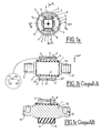
- the honeycomb joint according to the invention has a cylindrical piece 1 forming an axis which has at its ends square-section connections 11 and 12 connected to the axis 1 by a shoulder 14. These connections 11 and 12 serve to fix the articulation to a bogie or a box of a railway vehicle.
- An outer cylindrical tube 3 coaxial with the axis 1 (Y direction) is intended to be housed in the head of a rod.
- the hinged knuckle joint ( Figures 1b and 1c ) comprises two arms 5 which are cylindrical sectors adhered to the axis 1 and the tube 3. These two arms terminate on either side of their plane of symmetry (parallel to the Z axis, which in the application envisaged, is vertical) by concave ends 6 which define two spaces 8 which constitute cylindrical sectors for accommodating the abutment.
- the abutment comprises a cylindrical sector 4 of elastomer which is adhered to the axis 1 and a stop piece 2 of metal which, in the rest position shown in the figures, is spaced by a region 9 of the inner edge of the outer tube 3 , to define a clearance between the vertex 24 of the rounded vertex region 21 of the workpiece 2 and the inner contour of the tube 3.
- the piece 2 has, in longitudinal section, a convex region of vertex 21 having an apex 24, this vertex region 21 being bordered by two line segments 22 and 23 forming an angle ⁇ with the axis Y.
- the transverse direction X is that of movement of the train
- the longitudinal direction y of the articulation is the transverse direction of the train
- the z axis is the vertical.
- the function of the articulation is to have a high radial rigidity in the vertical direction Z (second direction), and in the X direction (first direction) a low rigidity to ensure comfort and filtration of noise, then a high stiffness under strong radial stresses.
- the high rigidity in the Z direction and the low rigidity in the X direction is provided by the elastomer arms 5.
- the cylindrical sector 4 made of elastomer ensures the high stiffness function which is sought in the X direction for high loads.
- the stops 2 are distinct elements of the arms 5 and are housed in the cells or spaces 8 between their ends. 6.
- This abutment effect is accompanied by a wear-resistant metal-to-metal contact between the part 2 and the tube 3 and which presents no practical inconvenience because the docking noise is dampened by the cylindrical elastomer sectors. 4.
- the outer contour of the part 2 is profiled so as to present (in longitudinal section) a convex profile with a rounded vertex region 21 having a top 24 located in the middle of the tube 3 in the Y direction, this region 21 being bordered by two straight segments 22 and 23.
- the part 2 bears on the cylindrical sector 4 in the vicinity of its middle which avoids a concentration of the stresses at the ends 7 of the cylindrical sectors 4 and a fatigue of the elastomer that constitutes them.
- the maximum angle is reached, it is a flat support on one of the line segments 22 or 23 with the tube 3, which also avoids a concentration of stresses at the ends 7 of the cylindrical sectors 4.
- the elastomer surface of the abutment can be increased, and for this purpose the cylindrical sectors 4, as well as the part 2 and the axis 1 protrude longitudinally on either side of the tube 3
- the ends 7 of the circular sectors 4 form a concave meniscus, for example semicircular.
Landscapes
- Engineering & Computer Science (AREA)
- Mechanical Engineering (AREA)
- General Engineering & Computer Science (AREA)
- Springs (AREA)
- Mutual Connection Of Rods And Tubes (AREA)
- Vibration Prevention Devices (AREA)
Abstract
Description
- La présente invention a pour objet une articulation alvéolée notamment pour une bielle d'entraînement qui fait partie d'un dispositif d'entraînement caisse-bogie pour un train.
- Une articulation alvéolée a pour but d'avoir des rigidités radiales très différentes suivant des axes de sollicitations perpendiculaires. L'écart de rigidité est en général réglé par la taille des alvéoles qui peuvent être traversantes ou non.
- Dans l'application envisagée, l'articulation doit présenter d'une part dans une première direction une souplesse élevée pour assurer le confort et la filtration, ainsi qu'une fonction supplémentaire, à savoir une forte raideur pour des sollicitations radiales fortes, et d'autre part, une raideur élevée dans une deuxième direction perpendiculaire à la première.
- La mise en oeuvre selon l'invention d'une articulation alvéolée à butée permet de réaliser cette fonction supplémentaire dans un volume réduit.
- L'invention concerne aussi une articulation alvéolée comportant un axe central et un tube extérieur caractérisée en ce qu'elle comporte :
- deux bras en élastomère formant des secteurs cylindriques ayant un premier plan de symétrie et diamétralement opposés, adhérisés sur une partie du contour curviligne de l'axe central et du tube extérieur de sorte qu'ils sont séparés par deux espaces,
- deux butées qui sont logées dans lesdits espaces et qui ont un deuxième plan de symétrie perpendiculaire au premier plan de symétrie, chaque butée comprenant un secteur cylindrique en élastomère adhérisé à l'axe central et à une pièce de butée en matériau rigide qui est espacée du tube extérieur lorsque l'articulation est au repos.
- Dans cette configuration, les bras en élastomère assurent la souplesse élevée dans la première direction, et la raideur élevée dans la deuxième direction, et les secteurs circulaires en caoutchouc servent à assurer la forte raideur désirée lorsque la butée vient en contact avec le tube extérieur. Cette mise en contact s'effectue par une pièce rigide, de préférence métallique, ce qui évite une usure rapide par abrasion.
- Pour satisfaire à une contrainte supplémentaire, à savoir la présence d'un mouvement conique important, l'articulation est caractérisée en ce que, en coupe longitudinale, les pièces de butée présentent un profil convexe dirigé vers le tube extérieur. De la sorte, on évite un pincement localisé de l'élastomère à une extrémité longitudinale, ce qui serait le cas avec une pièce de butée cylindrique.
- Plus particulièrement, le profil convexe présente un sommet situé au voisinage du milieu du tube extérieur. De préférence, le profil convexe présente, en coupe longitudinale, une région de sommet arrondi avantageusement bordée de deux segments de droite inclinés d'un angle α, par rapport à l'axe du tube extérieur par exemple compris entre 5° et 12° et notamment égal à 10°.
- La présence d'un sommet arrondi permet, lors d'un mouvement conique, que le point de contact entre la pièce de butée et le tube extérieur reste situé au voisinage du sommet, ce qui permet d'éviter une concentration de contraintes au niveau de la couche de caoutchouc.
- Avantageusement, l'articulation est caractérisée en ce que l'axe central déborde longitudinalement de part et d'autre du tube externe de même que les pièces de butée.
- De manière à éviter un gonflement de l'élastomère lorsque la butée est sous contrainte, les extrémités des secteurs cylindriques sont avantageusement concaves, par exemple pour former en coupe transversale des secteurs semi-circulaires.
- Il est avantageux que les bords des bras en élastomère qui délimitent lesdits espaces soient concaves en coupe transversale.
- L'axe central peut être équipé à ses extrémités d'éléments de montage sur un élément de structure d'un véhicule ferroviaire.
- D'autres caractéristiques et avantages de l'invention apparaîtront mieux à la lecture de la description ci-après en liaison avec les dessins dans lesquels :
- les
figures 1a à 1c sont respectivement une coupe transversale, une coupe longitudinale AA et une coupe AB d'une articulation selon un mode préféré de réalisation de l'invention, - les
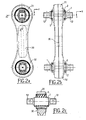
figures 2a, 2b et 2c sont respectivement une vue en plan, une vue latérale et une coupe AB d'une bielle pour dispositif d'entraînement caisse-bogie, équipée de deux articulations selon lesfigures 1a à 1c . - Selon les
figures 1 a à 1 c, l'articulation alvéolée selon l'invention présente une pièce cylindrique 1 formant un axe qui présente à ses extrémités des raccords 11 et 12 de section carrée raccordés à l'axe 1 par un épaulement 14. Ces raccords 11 et 12 servent à fixer l'articulation à un bogie ou à une caisse d'un véhicule ferroviaire. Un tube cylindrique externe 3 coaxial à l'axe 1 (direction Y) est destiné à être logé dans la tête d'une bielle. - L'articulation alvéolée à butée (
figures 1b et 1c ) comporte deux bras 5 qui sont des secteurs cylindriques adhérisés à l'axe 1 et au tube 3. Ces deux bras se terminent de part et d'autre de leur plan de symétrie (parallèle à l'axe Z, qui dans l'application envisagée, est vertical) par des extrémités 6 concaves qui définissent deux espaces 8 qui constituent des secteurs cylindriques permettant de loger la butée. - La butée comporte un secteur cylindrique 4 en élastomère qui est adhérisé à l'axe 1 et à une pièce de butée 2 en métal qui, dans la position de repos représentée aux figures, est espacée par une région 9 du bord interne du tube externe 3, pour définir un jeu entre le sommet 24 de la région de sommet arrondie 21 de la pièce 2 et le contour interne du tube 3. Comme représenté en encadré agrandi de la
figure 1b , la pièce 2 présente, en coupe longitudinale, une région de sommet 21 convexe ayant un sommet 24, cette région de sommet 21 étant bordée de deux segments de droite 22 et 23 faisant un angle α avec l'axe Y. - La direction transversale X est celle de déplacement du train, la direction longitudinale y de l'articulation est la direction transversale du train et l'axe z est la verticale.
- L'articulation a pour fonction de présenter une rigidité radiale élevée dans la direction verticale Z (deuxième direction), et dans la direction X (première direction) une rigidité faible pour assurer le confort et la filtration des bruits, puis une forte raideur sous des sollicitations radiales fortes.
- La rigidité élevée dans la direction Z et la faible rigidité dans la direction X est apportée par les bras en élastomère 5.
- Le secteur cylindrique 4 en élastomère assure la fonction de raideur élevée qui est recherchée dans la direction X pour les fortes sollicitations.
- On notera ici que, contrairement à des articulations alvéolées connues, où un même élément élastomère alvéolé assure les fonctions différentes dans les deux directions orthogonales, les butées 2 sont des éléments distincts des bras 5 et sont logées dans les alvéoles ou espaces 8 entre leurs extrémités 6.
- Pour les faibles sollicitations de l'articulation dans la direction X de déplacement du véhicule ferroviaire, l'élasticité est donc obtenue par les bras 5.
- Pour des charges plus élevées, dans la direction X, le jeu entre le sommet 24 et le tube 3 s'annule et la raideur est alors définie par les secteurs cylindriques 4.
- Cet effet de butée s'accompagne d'un contact métal-métal résistant à l'usure entre la pièce 2 et le tube 3 et qui ne présente pas d'inconvénient pratique car le bruit d'accostage est amorti par les secteurs cylindriques en élastomère 4.
- Pour permettre un fonctionnement avec des angles coniques, par exemple de 10°, sous sollicitation radiale dans la direction X, le contour externe de la pièce 2 est profilé de manière à présenter (en coupe longitudinale) un profil convexe avec une région de sommet arrondie 21 présentant un sommet 24 situé au milieu du tube 3 dans la direction Y, cette région 21 étant bordée par deux segments de droite 22 et 23.
- L'angle α que font ces deux segments de droites 22 et 23 avec la direction Y déterminent la valeur maximale de l'angle conique.
- Sous l'action d'une déformation conique, l'axe longitudinal de l'articulation ne reste pas parallèle à la direction Y, mais le point de contact entre la pièce de butée et l'intérieur du tube 3 reste localisé dans la région de sommet 21.
- Ainsi, même sous de fortes charges et un angle conique élevé sous sollicitation radiale dans la direction X, la pièce 2 appuie sur le secteur cylindrique 4 au voisinage de son milieu ce qui évite une concentration des contraintes aux extrémités 7 des secteurs cylindriques 4 et une fatigue de l'élastomère qui les constitue. Lorsque l'angle maximal est atteint, on a un appui à plat sur un des segments de droite 22 ou 23 avec le tube 3, ce qui évite aussi une concentration de contraintes aux extrémités 7 des secteurs cylindriques 4.
- Pour permettre une meilleure tenue en fatigue, la surface d'élastomère de la butée peut être augmentée, et à cet effet les secteurs cylindriques 4, ainsi que la pièce 2 et l'axe 1 dépassent longitudinalement de part et d'autre du tube 3
- Pour limiter les gonflements de l'élastomère et augmenter la durée de vie, les extrémités 7 des secteurs circulaires 4 forment un ménisque concave par exemple semi-circulaire.
Claims (11)
- Articulation alvéolée comportant un axe central et un tube extérieur qui comporte :- deux bras en élastomère (5) formant des secteurs cylindriques ayant un premier plan de symétrie et diamétralement opposés, adhérisés sur une partie du contour curviligne de l'axe central (1) et du tube extérieur (3) de sorte qu'ils sont séparés par deux espaces (8),- deux butées qui sont logées dans lesdits espaces (8) et qui ont un deuxième plan de symétrie perpendiculaire au premier plan de symétrie, caractérisée en ce que chaque butée comprend une pièce de butée (2) en matériau rigide et un secteur cylindrique (4) en élastomère adhérisé à l'axe central (1) et à la face interne de la pièce de butée (2) dont la face externe est espacée du tube extérieur (3) lorsque l'articulation est au repos.
- Articulation selon la revendication 1, caractérisé en ce que, en coupe longitudinale, les pièces de butée (2) présentent un profil convexe dirigé vers le tube extérieur (3).
- Articulation selon la revendication 2, caractérisé en ce que le profil convexe présente un sommet (24) situé au voisinage du milieu du tube extérieur (3).
- Articulation selon une des revendications 2 ou 3, caractérisé en ce que le profil convexe présente en coupe longitudinale une région de sommet arrondie (21).
- Articulation selon la revendication 4, caractérisé en ce que la région de sommet arrondie (21) est bordée de deux segments de droite (22, 23) inclinés d'un angle α avec l'axe du tube (3).
- Articulation selon une des revendications 4 ou 5, caractérisé en ce que l'angle α est compris entre 5° et 12° et notamment égal à 10°.
- Articulation selon une des revendications précédentes, caractérisé en ce que l'axe central (1) déborde longitudinalement de part et d'autre du tube externe (3) de même que les secteurs cylindriques (4) des butées et les pièces de butée (2).
- Articulation selon une des revendications précédentes, caractérisé en ce que les extrémités (7) des secteurs cylindriques (4) des butées sont concaves.
- Articulation selon la revendication 8, caractérisé en ce que les extrémités (7) des secteurs cylindriques (4) forment des ménisques concaves qui, en coupe transversales, sont sensiblement semi-circulaires.
- Articulation selon une des revendications précédentes, caractérisé en ce que les bords (6) des bras en élastomère (5) qui délimitent lesdits espaces (8) sont concaves en coupe transversale.
- Articulation selon une des revendications précédentes, caractérisé en ce que l'axe central (1) présente à ses deux extrémités des éléments de montage (11, 12) sur un élément de structure d'un véhicule ferroviaire.
Priority Applications (1)
| Application Number | Priority Date | Filing Date | Title |
|---|---|---|---|
| PL08291164T PL2072368T3 (pl) | 2007-12-17 | 2008-12-10 | Przegub z wnękami, zwłaszcza dla korbowodu napędowego |
Applications Claiming Priority (1)
| Application Number | Priority Date | Filing Date | Title |
|---|---|---|---|
| FR0708806A FR2925134B1 (fr) | 2007-12-17 | 2007-12-17 | Articulation alveolee notamment pour bielle d'entrainement |
Publications (2)
| Publication Number | Publication Date |
|---|---|
| EP2072368A1 true EP2072368A1 (fr) | 2009-06-24 |
| EP2072368B1 EP2072368B1 (fr) | 2012-06-27 |
Family
ID=39535276
Family Applications (1)
| Application Number | Title | Priority Date | Filing Date |
|---|---|---|---|
| EP08291164A Not-in-force EP2072368B1 (fr) | 2007-12-17 | 2008-12-10 | Articulation alvéolée notamment pour bielle d'entraînement |
Country Status (7)
| Country | Link |
|---|---|
| US (1) | US8272802B2 (fr) |
| EP (1) | EP2072368B1 (fr) |
| CN (1) | CN101462547B (fr) |
| CA (1) | CA2646614C (fr) |
| ES (1) | ES2392367T3 (fr) |
| FR (1) | FR2925134B1 (fr) |
| PL (1) | PL2072368T3 (fr) |
Families Citing this family (4)
| Publication number | Priority date | Publication date | Assignee | Title |
|---|---|---|---|---|
| JP6135205B2 (ja) * | 2013-03-11 | 2017-05-31 | 三菱自動車工業株式会社 | ロールロッド |
| JP6518139B2 (ja) * | 2015-06-12 | 2019-05-22 | 株式会社ブリヂストン | 防振装置 |
| JP2017101737A (ja) * | 2015-12-01 | 2017-06-08 | 住友理工株式会社 | 防振装置 |
| DE102016123501B4 (de) * | 2016-12-05 | 2020-11-26 | Vibracoustic Gmbh | Kern und Lager umfassend einen derartigen Kern |
Citations (4)
| Publication number | Priority date | Publication date | Assignee | Title |
|---|---|---|---|---|
| JP2000088026A (ja) * | 1998-09-14 | 2000-03-28 | Tokai Rubber Ind Ltd | ゴムブッシュおよびその製造方法 |
| DE19913777C1 (de) | 1999-03-26 | 2001-01-11 | Joern Gmbh | Gelenklager, insbesondere zur Lagerung von Achslenkern in Kraftfahrzeugen |
| JP2003072543A (ja) * | 2001-09-06 | 2003-03-12 | Hitachi Ltd | 鉄道車両 |
| EP1586789A1 (fr) * | 2004-04-15 | 2005-10-19 | Jörn GmbH | Support élastique pour une cabine de véhicule |
Family Cites Families (28)
| Publication number | Priority date | Publication date | Assignee | Title |
|---|---|---|---|---|
| US4007924A (en) * | 1975-06-27 | 1977-02-15 | Raoul Jorn | Elastic support mount |
| DE2630205A1 (de) * | 1976-07-05 | 1978-01-19 | Hurth Masch Zahnrad Carl | Kippzapfen fuer gelenke, insbesondere kardangelenke o.dgl. |
| JP2583212B2 (ja) * | 1985-05-27 | 1997-02-19 | 日産自動車株式会社 | 振動減衰装置 |
| US4872651A (en) * | 1988-03-14 | 1989-10-10 | Lord Corporation | Fluid filled resilient bushing |
| DE3909609A1 (de) * | 1989-03-23 | 1990-10-04 | Freudenberg Carl Fa | Huelsengummifeder |
| FR2695972B1 (fr) * | 1992-09-21 | 1994-11-18 | Hutchinson | Dispositif d'articulation élastique, en particulier pour triangle de suspension avant de véhicule. |
| US5374038A (en) * | 1993-04-27 | 1994-12-20 | Gencorp Inc. | Automotive torque strut bushing |
| FR2728949A1 (fr) * | 1995-01-04 | 1996-07-05 | Hutchinson | Perfectionnements aux manchons de support antivibratoires hydrauliques |
| US5846014A (en) * | 1996-05-08 | 1998-12-08 | Empire Rubber (Australia) Pty. Ltd. | Resilient joint |
| JP3706680B2 (ja) * | 1996-06-18 | 2005-10-12 | 本田技研工業株式会社 | 液体封入ブッシュ |
| DE19626535C2 (de) * | 1996-07-02 | 1999-10-14 | Daimler Chrysler Ag | Hydraulisch dämpfendes Elastomerlager |
| JP3811256B2 (ja) * | 1997-06-03 | 2006-08-16 | 本田技研工業株式会社 | 自動車のサスペンション用液体封入ブッシュ |
| US6517062B2 (en) * | 1999-03-08 | 2003-02-11 | Tokai Rubber Industries, Ltd. | Vibration isolator |
| FR2793854B1 (fr) * | 1999-05-21 | 2001-07-27 | Hutchinson | Bielle destinee a limiter des debattements relatifs entre deux elements rigides |
| US6430774B1 (en) * | 1999-07-02 | 2002-08-13 | The Pullman Company | Crimped bushing |
| FR2812363B1 (fr) * | 2000-07-31 | 2003-01-17 | Hutchinson | Manchon antivibratoire hydraulique |
| US6698731B2 (en) * | 2002-04-24 | 2004-03-02 | The Pullman Company | High compliance multiple chamber piston for fluid damped elastomer devices |
| US6899323B2 (en) * | 2002-09-05 | 2005-05-31 | Toyo Tire & Rubber Co., Ltd. | Vibration-isolating bushing |
| JP2004161249A (ja) * | 2002-09-27 | 2004-06-10 | Tokai Rubber Ind Ltd | ステアリングホイールの連結構造及び装置 |
| JP2004150537A (ja) * | 2002-10-30 | 2004-05-27 | Tokai Rubber Ind Ltd | 縦置式のサスペンションゴムブッシュ |
| DE10258986B4 (de) * | 2002-12-16 | 2005-07-14 | ZF Lemförder Metallwaren AG | Elastisches Fahrwerklager für Nutzfahrzeuge |
| JP4196401B2 (ja) * | 2003-05-30 | 2008-12-17 | 東海ゴム工業株式会社 | 流体封入式筒形防振装置 |
| FR2868140B1 (fr) * | 2004-03-29 | 2008-03-07 | Hutchinson Sa | Dispositif antivibratoire pour vehicule et biellette comportant un tel dispositif |
| GB0409595D0 (en) * | 2004-04-29 | 2004-06-02 | Avon Vibration Man Syst Ltd | Bush assembly |
| JP2006022907A (ja) * | 2004-07-08 | 2006-01-26 | Tokai Rubber Ind Ltd | 液封式防振ブッシュ |
| FR2876428B1 (fr) * | 2004-10-11 | 2008-08-08 | Hutchinson Sa | Dispositif antivibratoire et vehicule comportant un tel dispositif |
| US7296786B2 (en) * | 2004-11-23 | 2007-11-20 | Honda Motor Co., Ltd. | Composite bushing having dual damping capability |
| JP2010159873A (ja) * | 2008-12-09 | 2010-07-22 | Tokai Rubber Ind Ltd | 流体封入式筒形防振装置 |
-
2007
- 2007-12-17 FR FR0708806A patent/FR2925134B1/fr not_active Expired - Fee Related
-
2008
- 2008-12-10 PL PL08291164T patent/PL2072368T3/pl unknown
- 2008-12-10 ES ES08291164T patent/ES2392367T3/es active Active
- 2008-12-10 EP EP08291164A patent/EP2072368B1/fr not_active Not-in-force
- 2008-12-15 CA CA2646614A patent/CA2646614C/fr active Active
- 2008-12-16 CN CN2008101866576A patent/CN101462547B/zh not_active Expired - Fee Related
- 2008-12-16 US US12/336,436 patent/US8272802B2/en not_active Expired - Fee Related
Patent Citations (4)
| Publication number | Priority date | Publication date | Assignee | Title |
|---|---|---|---|---|
| JP2000088026A (ja) * | 1998-09-14 | 2000-03-28 | Tokai Rubber Ind Ltd | ゴムブッシュおよびその製造方法 |
| DE19913777C1 (de) | 1999-03-26 | 2001-01-11 | Joern Gmbh | Gelenklager, insbesondere zur Lagerung von Achslenkern in Kraftfahrzeugen |
| JP2003072543A (ja) * | 2001-09-06 | 2003-03-12 | Hitachi Ltd | 鉄道車両 |
| EP1586789A1 (fr) * | 2004-04-15 | 2005-10-19 | Jörn GmbH | Support élastique pour une cabine de véhicule |
Also Published As
| Publication number | Publication date |
|---|---|
| CA2646614A1 (fr) | 2009-06-17 |
| FR2925134B1 (fr) | 2010-05-21 |
| PL2072368T3 (pl) | 2012-12-31 |
| ES2392367T3 (es) | 2012-12-10 |
| CA2646614C (fr) | 2016-12-13 |
| EP2072368B1 (fr) | 2012-06-27 |
| US8272802B2 (en) | 2012-09-25 |
| US20090151597A1 (en) | 2009-06-18 |
| CN101462547B (zh) | 2013-07-10 |
| CN101462547A (zh) | 2009-06-24 |
| FR2925134A1 (fr) | 2009-06-19 |
Similar Documents
| Publication | Publication Date | Title |
|---|---|---|
| EP2139718B1 (fr) | Dispositif d' absorption d'energie pour siege de vehicule automobile, assemblage et ensemble comprenant le dispositif | |
| EP1400408B1 (fr) | Projecteur de véhicule automobile comportant des moyens perfectionnés de liaison au châssis du véhicule | |
| FR2510211A1 (fr) | Joints a calotte spherique amortisseurs de vibrations et hermetiquement scelles | |
| EP2237987A2 (fr) | Dispositif et ensemble d'absorption d'énergie renforcés | |
| EP1612126B1 (fr) | Dispositif de châssis de véhicule automobile | |
| EP2072368B1 (fr) | Articulation alvéolée notamment pour bielle d'entraînement | |
| FR2973747A1 (fr) | Entretoise et profile pour glissiere de siege de vehicule automobile | |
| FR2841609A1 (fr) | Cale de retenue du pied des aubes de soufflante | |
| FR3092314A1 (fr) | Structure portante à profil adaptable de manière passive | |
| WO2011036372A1 (fr) | Essieu arriere directeur a support de palonnier d'actionneur decouple | |
| EP1603778B1 (fr) | Butee d 'absorption de choc pour vehicule automobile | |
| EP2382364B1 (fr) | Systeme d'articulation d'un capot de vehicule automobile et capot associe | |
| EP2178726B1 (fr) | Raclette d'essuyage pour balai d'essuie-vitres d'automobiles, comportant une partie d'articulation | |
| FR2998524A1 (fr) | Ensemble de pare-chocs pour vehicule automobile a deux demi-coques | |
| EP3366955B1 (fr) | Joint d'etancheite souple pour un aeronef | |
| EP3148823B1 (fr) | Bras de suspension pour vehicule automobile | |
| EP3256348B1 (fr) | Support central de pare-choc arrière | |
| FR2979130A1 (fr) | Insert de raidissement pour vehicule automobile, notamment pour augmenter la stabilite des corps creux d'un vehicule, et systemes d'absorption de chocs comprenant un tel insert. | |
| FR2929568A1 (fr) | Ensemble d'absorption d'energie et vehicule comprenant ledit ensemble. | |
| EP4067125A1 (fr) | Bague de maintien d'une biellette de barre stabilisatrice d'un vehicule automobile | |
| FR2767508A1 (fr) | Butoir, notamment pour vehicules | |
| EP1901946A2 (fr) | Aile avant de vehicule automobile a cloison d'etancheite deformable | |
| FR2794503A1 (fr) | Bielle antivibratoire | |
| FR2764242A1 (fr) | Dispositif de verrouillage de paliers sur une barre anti-devers pour vehicules | |
| EP1772297A1 (fr) | Traverse de train arrière de véhicule automobile |
Legal Events
| Date | Code | Title | Description |
|---|---|---|---|
| PUAI | Public reference made under article 153(3) epc to a published international application that has entered the european phase |
Free format text: ORIGINAL CODE: 0009012 |
|
| AK | Designated contracting states |
Kind code of ref document: A1 Designated state(s): AT BE BG CH CY CZ DE DK EE ES FI FR GB GR HR HU IE IS IT LI LT LU LV MC MT NL NO PL PT RO SE SI SK TR |
|
| AX | Request for extension of the european patent |
Extension state: AL BA MK RS |
|
| 17P | Request for examination filed |
Effective date: 20091208 |
|
| 17Q | First examination report despatched |
Effective date: 20100108 |
|
| AKX | Designation fees paid |
Designated state(s): AT BE BG CH CY CZ DE DK EE ES FI FR GB GR HR HU IE IS IT LI LT LU LV MC MT NL NO PL PT RO SE SI SK TR |
|
| GRAP | Despatch of communication of intention to grant a patent |
Free format text: ORIGINAL CODE: EPIDOSNIGR1 |
|
| GRAS | Grant fee paid |
Free format text: ORIGINAL CODE: EPIDOSNIGR3 |
|
| GRAA | (expected) grant |
Free format text: ORIGINAL CODE: 0009210 |
|
| AK | Designated contracting states |
Kind code of ref document: B1 Designated state(s): AT BE BG CH CY CZ DE DK EE ES FI FR GB GR HR HU IE IS IT LI LT LU LV MC MT NL NO PL PT RO SE SI SK TR |
|
| REG | Reference to a national code |
Ref country code: GB Ref legal event code: FG4D Free format text: NOT ENGLISH |
|
| REG | Reference to a national code |
Ref country code: CH Ref legal event code: EP |
|
| REG | Reference to a national code |
Ref country code: AT Ref legal event code: REF Ref document number: 564016 Country of ref document: AT Kind code of ref document: T Effective date: 20120715 |
|
| REG | Reference to a national code |
Ref country code: IE Ref legal event code: FG4D Free format text: LANGUAGE OF EP DOCUMENT: FRENCH |
|
| REG | Reference to a national code |
Ref country code: DE Ref legal event code: R096 Ref document number: 602008016723 Country of ref document: DE Effective date: 20120823 |
|
| PG25 | Lapsed in a contracting state [announced via postgrant information from national office to epo] |
Ref country code: LT Free format text: LAPSE BECAUSE OF FAILURE TO SUBMIT A TRANSLATION OF THE DESCRIPTION OR TO PAY THE FEE WITHIN THE PRESCRIBED TIME-LIMIT Effective date: 20120627 Ref country code: FI Free format text: LAPSE BECAUSE OF FAILURE TO SUBMIT A TRANSLATION OF THE DESCRIPTION OR TO PAY THE FEE WITHIN THE PRESCRIBED TIME-LIMIT Effective date: 20120627 Ref country code: NO Free format text: LAPSE BECAUSE OF FAILURE TO SUBMIT A TRANSLATION OF THE DESCRIPTION OR TO PAY THE FEE WITHIN THE PRESCRIBED TIME-LIMIT Effective date: 20120927 Ref country code: SE Free format text: LAPSE BECAUSE OF FAILURE TO SUBMIT A TRANSLATION OF THE DESCRIPTION OR TO PAY THE FEE WITHIN THE PRESCRIBED TIME-LIMIT Effective date: 20120627 |
|
| REG | Reference to a national code |
Ref country code: NL Ref legal event code: T3 |
|
| REG | Reference to a national code |
Ref country code: LT Ref legal event code: MG4D Effective date: 20120627 |
|
| PG25 | Lapsed in a contracting state [announced via postgrant information from national office to epo] |
Ref country code: HR Free format text: LAPSE BECAUSE OF FAILURE TO SUBMIT A TRANSLATION OF THE DESCRIPTION OR TO PAY THE FEE WITHIN THE PRESCRIBED TIME-LIMIT Effective date: 20120627 Ref country code: LV Free format text: LAPSE BECAUSE OF FAILURE TO SUBMIT A TRANSLATION OF THE DESCRIPTION OR TO PAY THE FEE WITHIN THE PRESCRIBED TIME-LIMIT Effective date: 20120627 Ref country code: GR Free format text: LAPSE BECAUSE OF FAILURE TO SUBMIT A TRANSLATION OF THE DESCRIPTION OR TO PAY THE FEE WITHIN THE PRESCRIBED TIME-LIMIT Effective date: 20120928 Ref country code: SI Free format text: LAPSE BECAUSE OF FAILURE TO SUBMIT A TRANSLATION OF THE DESCRIPTION OR TO PAY THE FEE WITHIN THE PRESCRIBED TIME-LIMIT Effective date: 20120627 |
|
| REG | Reference to a national code |
Ref country code: ES Ref legal event code: FG2A Ref document number: 2392367 Country of ref document: ES Kind code of ref document: T3 Effective date: 20121210 |
|
| REG | Reference to a national code |
Ref country code: PL Ref legal event code: T3 |
|
| PG25 | Lapsed in a contracting state [announced via postgrant information from national office to epo] |
Ref country code: SK Free format text: LAPSE BECAUSE OF FAILURE TO SUBMIT A TRANSLATION OF THE DESCRIPTION OR TO PAY THE FEE WITHIN THE PRESCRIBED TIME-LIMIT Effective date: 20120627 Ref country code: CY Free format text: LAPSE BECAUSE OF FAILURE TO SUBMIT A TRANSLATION OF THE DESCRIPTION OR TO PAY THE FEE WITHIN THE PRESCRIBED TIME-LIMIT Effective date: 20120627 Ref country code: EE Free format text: LAPSE BECAUSE OF FAILURE TO SUBMIT A TRANSLATION OF THE DESCRIPTION OR TO PAY THE FEE WITHIN THE PRESCRIBED TIME-LIMIT Effective date: 20120627 Ref country code: IS Free format text: LAPSE BECAUSE OF FAILURE TO SUBMIT A TRANSLATION OF THE DESCRIPTION OR TO PAY THE FEE WITHIN THE PRESCRIBED TIME-LIMIT Effective date: 20121027 Ref country code: RO Free format text: LAPSE BECAUSE OF FAILURE TO SUBMIT A TRANSLATION OF THE DESCRIPTION OR TO PAY THE FEE WITHIN THE PRESCRIBED TIME-LIMIT Effective date: 20120627 |
|
| PG25 | Lapsed in a contracting state [announced via postgrant information from national office to epo] |
Ref country code: PT Free format text: LAPSE BECAUSE OF FAILURE TO SUBMIT A TRANSLATION OF THE DESCRIPTION OR TO PAY THE FEE WITHIN THE PRESCRIBED TIME-LIMIT Effective date: 20121029 |
|
| PG25 | Lapsed in a contracting state [announced via postgrant information from national office to epo] |
Ref country code: DK Free format text: LAPSE BECAUSE OF FAILURE TO SUBMIT A TRANSLATION OF THE DESCRIPTION OR TO PAY THE FEE WITHIN THE PRESCRIBED TIME-LIMIT Effective date: 20120627 |
|
| PLBE | No opposition filed within time limit |
Free format text: ORIGINAL CODE: 0009261 |
|
| STAA | Information on the status of an ep patent application or granted ep patent |
Free format text: STATUS: NO OPPOSITION FILED WITHIN TIME LIMIT |
|
| 26N | No opposition filed |
Effective date: 20130328 |
|
| BERE | Be: lapsed |
Owner name: HUTCHINSON Effective date: 20121231 |
|
| REG | Reference to a national code |
Ref country code: DE Ref legal event code: R097 Ref document number: 602008016723 Country of ref document: DE Effective date: 20130328 |
|
| PG25 | Lapsed in a contracting state [announced via postgrant information from national office to epo] |
Ref country code: BG Free format text: LAPSE BECAUSE OF FAILURE TO SUBMIT A TRANSLATION OF THE DESCRIPTION OR TO PAY THE FEE WITHIN THE PRESCRIBED TIME-LIMIT Effective date: 20120927 Ref country code: MC Free format text: LAPSE BECAUSE OF NON-PAYMENT OF DUE FEES Effective date: 20121231 |
|
| REG | Reference to a national code |
Ref country code: CH Ref legal event code: PL |
|
| REG | Reference to a national code |
Ref country code: IE Ref legal event code: MM4A |
|
| PG25 | Lapsed in a contracting state [announced via postgrant information from national office to epo] |
Ref country code: BE Free format text: LAPSE BECAUSE OF NON-PAYMENT OF DUE FEES Effective date: 20121231 |
|
| PG25 | Lapsed in a contracting state [announced via postgrant information from national office to epo] |
Ref country code: IE Free format text: LAPSE BECAUSE OF NON-PAYMENT OF DUE FEES Effective date: 20121210 Ref country code: LI Free format text: LAPSE BECAUSE OF NON-PAYMENT OF DUE FEES Effective date: 20121231 Ref country code: CH Free format text: LAPSE BECAUSE OF NON-PAYMENT OF DUE FEES Effective date: 20121231 |
|
| PG25 | Lapsed in a contracting state [announced via postgrant information from national office to epo] |
Ref country code: MT Free format text: LAPSE BECAUSE OF FAILURE TO SUBMIT A TRANSLATION OF THE DESCRIPTION OR TO PAY THE FEE WITHIN THE PRESCRIBED TIME-LIMIT Effective date: 20120627 |
|
| PG25 | Lapsed in a contracting state [announced via postgrant information from national office to epo] |
Ref country code: TR Free format text: LAPSE BECAUSE OF FAILURE TO SUBMIT A TRANSLATION OF THE DESCRIPTION OR TO PAY THE FEE WITHIN THE PRESCRIBED TIME-LIMIT Effective date: 20120627 |
|
| PG25 | Lapsed in a contracting state [announced via postgrant information from national office to epo] |
Ref country code: LU Free format text: LAPSE BECAUSE OF NON-PAYMENT OF DUE FEES Effective date: 20121210 |
|
| PG25 | Lapsed in a contracting state [announced via postgrant information from national office to epo] |
Ref country code: HU Free format text: LAPSE BECAUSE OF FAILURE TO SUBMIT A TRANSLATION OF THE DESCRIPTION OR TO PAY THE FEE WITHIN THE PRESCRIBED TIME-LIMIT Effective date: 20081210 |
|
| REG | Reference to a national code |
Ref country code: FR Ref legal event code: PLFP Year of fee payment: 8 |
|
| REG | Reference to a national code |
Ref country code: FR Ref legal event code: PLFP Year of fee payment: 9 |
|
| REG | Reference to a national code |
Ref country code: FR Ref legal event code: PLFP Year of fee payment: 10 |
|
| PGFP | Annual fee paid to national office [announced via postgrant information from national office to epo] |
Ref country code: NL Payment date: 20221222 Year of fee payment: 15 Ref country code: GB Payment date: 20221222 Year of fee payment: 15 Ref country code: FR Payment date: 20221125 Year of fee payment: 15 Ref country code: DE Payment date: 20221213 Year of fee payment: 15 Ref country code: CZ Payment date: 20221207 Year of fee payment: 15 Ref country code: AT Payment date: 20221222 Year of fee payment: 15 |
|
| PGFP | Annual fee paid to national office [announced via postgrant information from national office to epo] |
Ref country code: PL Payment date: 20221208 Year of fee payment: 15 |
|
| PGFP | Annual fee paid to national office [announced via postgrant information from national office to epo] |
Ref country code: ES Payment date: 20230224 Year of fee payment: 15 |
|
| PGFP | Annual fee paid to national office [announced via postgrant information from national office to epo] |
Ref country code: IT Payment date: 20221228 Year of fee payment: 15 |
|
| REG | Reference to a national code |
Ref country code: DE Ref legal event code: R119 Ref document number: 602008016723 Country of ref document: DE |
|
| PG25 | Lapsed in a contracting state [announced via postgrant information from national office to epo] |
Ref country code: CZ Free format text: LAPSE BECAUSE OF NON-PAYMENT OF DUE FEES Effective date: 20231210 |
|
| PG25 | Lapsed in a contracting state [announced via postgrant information from national office to epo] |
Ref country code: CZ Free format text: LAPSE BECAUSE OF NON-PAYMENT OF DUE FEES Effective date: 20231210 |
|
| REG | Reference to a national code |
Ref country code: NL Ref legal event code: MM Effective date: 20240101 |
|
| REG | Reference to a national code |
Ref country code: AT Ref legal event code: MM01 Ref document number: 564016 Country of ref document: AT Kind code of ref document: T Effective date: 20231210 |
|
| GBPC | Gb: european patent ceased through non-payment of renewal fee |
Effective date: 20231210 |
|
| PG25 | Lapsed in a contracting state [announced via postgrant information from national office to epo] |
Ref country code: NL Free format text: LAPSE BECAUSE OF NON-PAYMENT OF DUE FEES Effective date: 20240101 |
|
| PG25 | Lapsed in a contracting state [announced via postgrant information from national office to epo] |
Ref country code: NL Free format text: LAPSE BECAUSE OF NON-PAYMENT OF DUE FEES Effective date: 20240101 |
|
| PG25 | Lapsed in a contracting state [announced via postgrant information from national office to epo] |
Ref country code: DE Free format text: LAPSE BECAUSE OF NON-PAYMENT OF DUE FEES Effective date: 20240702 |
|
| PG25 | Lapsed in a contracting state [announced via postgrant information from national office to epo] |
Ref country code: GB Free format text: LAPSE BECAUSE OF NON-PAYMENT OF DUE FEES Effective date: 20231210 |
|
| PG25 | Lapsed in a contracting state [announced via postgrant information from national office to epo] |
Ref country code: FR Free format text: LAPSE BECAUSE OF NON-PAYMENT OF DUE FEES Effective date: 20231231 |
|
| PG25 | Lapsed in a contracting state [announced via postgrant information from national office to epo] |
Ref country code: AT Free format text: LAPSE BECAUSE OF NON-PAYMENT OF DUE FEES Effective date: 20231210 |
|
| PG25 | Lapsed in a contracting state [announced via postgrant information from national office to epo] |
Ref country code: GB Free format text: LAPSE BECAUSE OF NON-PAYMENT OF DUE FEES Effective date: 20231210 Ref country code: FR Free format text: LAPSE BECAUSE OF NON-PAYMENT OF DUE FEES Effective date: 20231231 Ref country code: DE Free format text: LAPSE BECAUSE OF NON-PAYMENT OF DUE FEES Effective date: 20240702 Ref country code: AT Free format text: LAPSE BECAUSE OF NON-PAYMENT OF DUE FEES Effective date: 20231210 |
|
| REG | Reference to a national code |
Ref country code: ES Ref legal event code: FD2A Effective date: 20250129 |
|
| PG25 | Lapsed in a contracting state [announced via postgrant information from national office to epo] |
Ref country code: ES Free format text: LAPSE BECAUSE OF NON-PAYMENT OF DUE FEES Effective date: 20231211 |
|
| PG25 | Lapsed in a contracting state [announced via postgrant information from national office to epo] |
Ref country code: PL Free format text: LAPSE BECAUSE OF NON-PAYMENT OF DUE FEES Effective date: 20231210 |
|
| PG25 | Lapsed in a contracting state [announced via postgrant information from national office to epo] |
Ref country code: IT Free format text: LAPSE BECAUSE OF NON-PAYMENT OF DUE FEES Effective date: 20231210 |