EP2072331A2 - Fixing device for a lighting unit and method of exchanging the bulb - Google Patents
Fixing device for a lighting unit and method of exchanging the bulb Download PDFInfo
- Publication number
- EP2072331A2 EP2072331A2 EP08019451A EP08019451A EP2072331A2 EP 2072331 A2 EP2072331 A2 EP 2072331A2 EP 08019451 A EP08019451 A EP 08019451A EP 08019451 A EP08019451 A EP 08019451A EP 2072331 A2 EP2072331 A2 EP 2072331A2
- Authority
- EP
- European Patent Office
- Prior art keywords
- lighting unit
- unit
- end position
- receiving
- fastening device
- Prior art date
- Legal status (The legal status is an assumption and is not a legal conclusion. Google has not performed a legal analysis and makes no representation as to the accuracy of the status listed.)
- Granted
Links
Images


Classifications
-
- B—PERFORMING OPERATIONS; TRANSPORTING
- B60—VEHICLES IN GENERAL
- B60Q—ARRANGEMENT OF SIGNALLING OR LIGHTING DEVICES, THE MOUNTING OR SUPPORTING THEREOF OR CIRCUITS THEREFOR, FOR VEHICLES IN GENERAL
- B60Q1/00—Arrangement of optical signalling or lighting devices, the mounting or supporting thereof or circuits therefor
- B60Q1/02—Arrangement of optical signalling or lighting devices, the mounting or supporting thereof or circuits therefor the devices being primarily intended to illuminate the way ahead or to illuminate other areas of way or environments
- B60Q1/04—Arrangement of optical signalling or lighting devices, the mounting or supporting thereof or circuits therefor the devices being primarily intended to illuminate the way ahead or to illuminate other areas of way or environments the devices being headlights
- B60Q1/0408—Arrangement of optical signalling or lighting devices, the mounting or supporting thereof or circuits therefor the devices being primarily intended to illuminate the way ahead or to illuminate other areas of way or environments the devices being headlights built into the vehicle body, e.g. details concerning the mounting of the headlamps on the vehicle body
- B60Q1/0416—Arrangement of optical signalling or lighting devices, the mounting or supporting thereof or circuits therefor the devices being primarily intended to illuminate the way ahead or to illuminate other areas of way or environments the devices being headlights built into the vehicle body, e.g. details concerning the mounting of the headlamps on the vehicle body the housing being mounted on the vehicle body using rails
-
- B—PERFORMING OPERATIONS; TRANSPORTING
- B60—VEHICLES IN GENERAL
- B60Q—ARRANGEMENT OF SIGNALLING OR LIGHTING DEVICES, THE MOUNTING OR SUPPORTING THEREOF OR CIRCUITS THEREFOR, FOR VEHICLES IN GENERAL
- B60Q1/00—Arrangement of optical signalling or lighting devices, the mounting or supporting thereof or circuits therefor
- B60Q1/0064—Arrangement of optical signalling or lighting devices, the mounting or supporting thereof or circuits therefor with provision for maintenance, e.g. changing the light bulb
-
- B—PERFORMING OPERATIONS; TRANSPORTING
- B60—VEHICLES IN GENERAL
- B60Q—ARRANGEMENT OF SIGNALLING OR LIGHTING DEVICES, THE MOUNTING OR SUPPORTING THEREOF OR CIRCUITS THEREFOR, FOR VEHICLES IN GENERAL
- B60Q1/00—Arrangement of optical signalling or lighting devices, the mounting or supporting thereof or circuits therefor
- B60Q1/02—Arrangement of optical signalling or lighting devices, the mounting or supporting thereof or circuits therefor the devices being primarily intended to illuminate the way ahead or to illuminate other areas of way or environments
- B60Q1/04—Arrangement of optical signalling or lighting devices, the mounting or supporting thereof or circuits therefor the devices being primarily intended to illuminate the way ahead or to illuminate other areas of way or environments the devices being headlights
- B60Q1/0408—Arrangement of optical signalling or lighting devices, the mounting or supporting thereof or circuits therefor the devices being primarily intended to illuminate the way ahead or to illuminate other areas of way or environments the devices being headlights built into the vehicle body, e.g. details concerning the mounting of the headlamps on the vehicle body
- B60Q1/0425—Arrangement of optical signalling or lighting devices, the mounting or supporting thereof or circuits therefor the devices being primarily intended to illuminate the way ahead or to illuminate other areas of way or environments the devices being headlights built into the vehicle body, e.g. details concerning the mounting of the headlamps on the vehicle body the housing being swivel mounted on the vehicle body
-
- B—PERFORMING OPERATIONS; TRANSPORTING
- B60—VEHICLES IN GENERAL
- B60Q—ARRANGEMENT OF SIGNALLING OR LIGHTING DEVICES, THE MOUNTING OR SUPPORTING THEREOF OR CIRCUITS THEREFOR, FOR VEHICLES IN GENERAL
- B60Q1/00—Arrangement of optical signalling or lighting devices, the mounting or supporting thereof or circuits therefor
- B60Q1/02—Arrangement of optical signalling or lighting devices, the mounting or supporting thereof or circuits therefor the devices being primarily intended to illuminate the way ahead or to illuminate other areas of way or environments
- B60Q1/04—Arrangement of optical signalling or lighting devices, the mounting or supporting thereof or circuits therefor the devices being primarily intended to illuminate the way ahead or to illuminate other areas of way or environments the devices being headlights
- B60Q1/0408—Arrangement of optical signalling or lighting devices, the mounting or supporting thereof or circuits therefor the devices being primarily intended to illuminate the way ahead or to illuminate other areas of way or environments the devices being headlights built into the vehicle body, e.g. details concerning the mounting of the headlamps on the vehicle body
- B60Q1/0441—Arrangement of optical signalling or lighting devices, the mounting or supporting thereof or circuits therefor the devices being primarily intended to illuminate the way ahead or to illuminate other areas of way or environments the devices being headlights built into the vehicle body, e.g. details concerning the mounting of the headlamps on the vehicle body the housing being fastened onto the vehicle body using means other than screws
Definitions
- the invention relates to a fastening device for a lighting unit to a body opening of a vehicle having a mountable on the body of the vehicle and a receiving trough receiving means comprising guide means for guiding the lighting unit along a translational trajectory between located within the receiving trough inner end position and a essentially located outside of the receiving trough outer end position thereof, with locking means for moving the located in the inner end position light unit from an unlocked state to a locked state and vice versa.
- the invention relates to a method for changing the light source of a lamp unit mounted in a body recess of a vehicle, wherein a housing of the lighting unit is unlocked in the body recess and along a translational guide track is moved from an inner end position.
- a fastening device for a lighting unit by means of which the lighting unit can be fastened in a body opening of a motor vehicle.
- the fastening device comprises, on the one hand, guide means, so that a housing of the lighting unit can be moved to an opening edge of the body opening along a translatory guide track into an end position within the body opening after attachment thereof.
- the fastening device comprises locking means, so that the housing of the lighting unit is held in the end position latching.
- a disadvantage of the known fastening device is that for disassembly of the lighting unit, the locking means must be actuated by a tool with the application of a force.
- a fastening device for lighting units is known, by means of which lighting units can be inserted into a body opening of a vehicle or removed again.
- the fastening device has as a guide means on a guide link, which is integrally formed on a receiving unit the light unit.
- the guide slot has two mutually perpendicular route sections, so that the lighting unit is moved by engaging a pin in the groove of the guide slot from an outer insertion position in which the lighting unit is arranged substantially in front of the body opening in an inner end position. In the inner end position of the lighting unit this is formed by a trained as a fastening screw locking means on a flange of the receiving device attached.
- Object of the present invention is therefore to provide a fastening device for a light unit and a method for attaching a light unit to a body opening such that the assembly and disassembly of the light unit is facilitated to change bulbs, without the aid of a tool is required.
- the fastening device in conjunction with the preamble of claim 1, characterized in that the receiving device as a guide means in the region of an edge of the receiving trough has a tilting unit, such that the lighting unit arranged inclined in the outer end position, exposing a rear side thereof is.
- the particular advantage of the invention is that the light unit for changing the light source does not have to be completely removed from the receiving device by the tilting unit integrated in the receiving device. Instead, the lighting unit is arranged in an outer end position in a tilted position, in which a rear side of the lighting unit is accessible for changing the lighting means.
- the lighting unit is arranged in an outer end position in a tilted position, in which a rear side of the lighting unit is accessible for changing the lighting means.
- no complete disassembly of the lighting unit for changing the light source is not required. The light source change can thus be done relatively quickly and easy to use.
- the tilting unit is formed by a hinge unit, wherein a hinge element of the lighting unit cooperates with a hinge element of the receiving device, so that the lighting unit can be moved out of the receiving recess into an intermediate position after translational movement outwards, in which the hinge element engage and pivot allow the lighting unit.
- the hinge elements are designed such that the lighting unit is pivoted to form an acute angle between a longitudinal axis of the lighting unit and a longitudinal axis of the receiving trough and held self-supporting in the outer end position.
- the hinge elements of the lighting unit on the one hand and the receiving device on the other hand in the inner end position spaced from each other.
- the hinge unit is thus effective only when the lighting unit has been moved out by a displacement from the receiving trough. Since now a front area of the lighting unit is arranged outside the body opening, the pivoting process can thus take place without wall parts of the receiving trough standing in the way.
- the hinge element of the lighting unit on the one hand and the receiving device on the other hand are complementary to each other.
- the hinge element of the lighting unit is fork-shaped, which surrounds the cylindrically shaped hinge element of the receiving device in the hinge position.
- the locking means are formed by a sliding / latching unit, which is arranged on a rear side of the receiving device.
- the light unit can be spent without the aid of tools from an unlocked position into a locking position and vice versa.
- the slider is slidably mounted at an angle to the vehicle longitudinal axis, preferably perpendicular to the vehicle longitudinal axis, the slide can be operated easy to use. He preferably has a resilient clamping element which is connected in the locking position latching with the pin of the light unit. As a result, a secure fixation of the lighting unit is given in the inner end position.
- the slide cooperates with a fixed element of the receiving device, so that the clamping element is clamped in the unlocked position.
- the slider can be advantageously held in a releasing the light unit position, so that the lamp unit is movable to expose the pin in the inner end position or from the inner end position for lamp replacement.
- the ejection movement of the lighting unit can thus be independent of the transverse movement of the slider.
- the method according to the invention in conjunction with the preamble of claim 12 is characterized in that the lighting unit is moved along the translational guide track to an intermediate position, and that the lighting unit then by a vertical pivoted to the translational guide track pivot axis is pivoted into an outer end position in which a rear side of the lighting unit is exposed.
- the particular advantage of the method according to the invention is that a light source change is made possible without the light unit having to be removed from the body opening.
- the light unit is brought while pushing it out of the body opening along the translational guide track in a tilted position in which a rear side of the lighting unit is freely accessible for lamp replacement.
- the tilting unit can be used for simplified mounting of the lighting unit.
- the lighting unit can be attached to the edge of the tilting unit and then moved by pivoting into the insertion position, in which the lighting unit is moved translationally into the inner end position.
- the assembly of the headlamp can be simplified as a result, since a defined attachment position is created by the tilting unit.
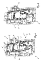
- a receiving device 1 can be designed as a front-end module, which can be fastened to a body of the motor vehicle via mounting brackets. Alternatively, the receiving device 1 may also be part of the body of the vehicle.
- the receiving device 1 has a receiving trough 2 for releasably securing a lighting unit 3. Like from the Figures 1 and 2 it can be seen, the receiving device 1 has an upper receiving trough 2 (body recess) for receiving a designed as a main headlamp light unit 3 and a lower receiving trough 2 'for receiving a designed as an additional headlamp light unit 3. In the following, only the attachment of the upper lighting unit 3 will be discussed.
- the fastening device has, on the one hand, a sliding / latching unit 4, which is arranged on a rear side 5 of the receiving device 1.
- the sliding / latching unit 4 has a rectilinear slide 6 which is mounted so as to be longitudinally displaceable in a slot formed by lugs 7 formed on the rear side 5 of the receiving device 1.
- the slider 6 is along a arranged perpendicular to a vehicle longitudinal axis extending sliding path 8 linearly movable.
- the slider 6 has at least one slot 9 and two spaced along the slider 6 to each other arranged clamping elements 10.
- the clamping elements 10 are designed as spring elements which have two spring arms 11, which are arranged transversely to the extension of the slider 6 resiliently. In accordance with FIG. 1 illustrated locking position of the slider 6 engage around the spring arms 11 latching a projecting from a rear side 12 of the light unit 3 pin 13, so that the light unit 3 is fixed in the receiving trough 2.
- a cross member 16 of the slider 6 is a fixed element 17 associated with the receiving device 1, so that the slider 6 can be fixed in the unlocked position. This ensures that during the insertion process of the lighting unit 3 into the receiving trough 2, the pin 13 can engage freely in the slot 9.
- a tilting unit 20 by means of which the lighting unit 3 after unlocking while moving along the translational guide track 14 about a pivot axis 21 along a rotary guide track 22 in an outer end position 23 is movable.
- the lighting unit 3 is held inclined at the edge 18 of the receiving opening 19, wherein the rear side 12 of the lighting unit 3 is accessible for making a change of light source.
- the tilting unit 20 forms a hinge unit, wherein a fork-shaped hinge element 24 of the lighting unit 3 engages around a cylindrical hinge element 25 of the receiving device 1 in the hinge position of the receiving device 1.
- the longitudinal axis of the hinge element 25 thus forms the pivot axis 21, which is skewed or perpendicular to the translational guide track 14 and perpendicular to the vehicle longitudinal axis.
- the hinge element 24 of the lighting unit 3 is arranged at a distance F to the hinge element 25 of the receiving device 1. This distance F corresponds to the length of the translatory guide track 14.
- the cylindrical hinge element 25 may also be formed on the extension 26 of the lighting unit 3 and the fork-shaped hinge element 24 on the receiving unit 1.
- the hinge element 24 of the lighting unit 3 extends at the end of an extension 26 of the lighting unit 3, which protrudes substantially below a housing of the lighting unit 3 at an angle from an underside.
- the hinge elements 25 of the receiving device 1 are arranged integrated in an attachable to the receiving device 1 insert member 27.
- the insert member 27 has a flat support threshold 28, so that the ends of the extension 6 are supported.
- the hinge element 25 of the receiving device 1 is shaped such that the lighting unit 3 can be pivoted about an acute or obtuse angle along the rotational trajectory 22, preferably 75 °. In an inclined outer end position of the lighting unit 3 abuts one end of a hinge arm 29 on a stop surface 30 of the hinge 25 at. In this outer end position 23, the lighting unit 3 is supported solely by the receiving device 1.
- the slider 6 is first moved from the locked position to an unlocked position.
- the lighting unit 3 can now be moved from the inner end position into an intermediate position 31, the lighting unit 3 being guided along a translatory guide track 14.
- the receiving device 1 on side walls elongated ribs 32 on which lugs 33 of the light unit 3 slide along.
- the lighting unit 3 By applying one in the axial direction the light unit 3 acting force the light unit 3 is now pivoted about the pivot axis 21 so far until it has reached the outer end position 23.
- the lighting means By opening a cap arranged on the back side of the lighting unit 3, the lighting means can now be exchanged.
- the hinge unit is designed so stable that the lighting unit 3 can be kept in the tilted state.
- this can be done by a light source change in a comfortable height of the light unit 3. It is ensured that the lighting unit 3 can not be removed automatically from the receiving device 1.
- the lighting unit 3 After changing the light source, the lighting unit 3 is pivoted back out of the outer end position 23 into the intermediate position 31 and subsequently moved along the translatory guide track 14 into the inner end position. By subsequently locking the slider 8, the lighting unit 3 is fixed again in the receiving trough 2.
- the receptacles may be formed as perforations or recesses, which allow a defined relative position of the lighting unit 3 to the receiving device 1.
- the lighting unit 3 For mounting the lighting unit 3, this can be applied by engaging the corresponding hinge elements 24 of the lighting unit 3 and the hinge elements 25 of the receiving device 1.
- the lighting unit 3 thus has a defined insertion position to the receiving device 1.
- the following can - as in the Lamp change - the lighting unit 3 are spent by pivoting along the rotary guideway 22 and subsequent displacement along the translational guide track in the inner end position, in which by locking means the locking of the light unit 3 takes place.
- two fastening tabs 40 are mounted on the back 5 of the receiving device 1 by means of screw 41.
- the elongate attachment tabs 40 extend substantially in the vertical direction or at a relatively small acute angle to a vertical plane.
- two fastening tabs 40 are provided, which are arranged at a distance from each other.
Landscapes
- Engineering & Computer Science (AREA)
- Mechanical Engineering (AREA)
- Lighting Device Outwards From Vehicle And Optical Signal (AREA)
Abstract
Description
Die Erfindung betrifft eine Befestigungsvorrichtung für eine Leuchteinheit an einer Karosserieöffnung eines Fahrzeugs mit einer an der Karosserie des Fahrzeugs befestigbaren und eine Aufnahmemulde aufweisenden Aufnahmeeinrichtung, die Führungsmittel aufweist zur Führung der Leuchteinheit entlang einer translatorischen Bewegungsbahn zwischen einer sich innerhalb der Aufnahmemulde befindlichen inneren Endstellung und einer sich im Wesentlichen außerhalb der Aufnahmemulde befindlichen äußeren Endstellung derselben, mit Verriegelungsmitteln zum Verbringen der sich in der inneren Endstellung befindenden Leuchteinheit aus einem Entriegelungszustand in einen Verriegelungszustand und vice versa.The invention relates to a fastening device for a lighting unit to a body opening of a vehicle having a mountable on the body of the vehicle and a receiving trough receiving means comprising guide means for guiding the lighting unit along a translational trajectory between located within the receiving trough inner end position and a essentially located outside of the receiving trough outer end position thereof, with locking means for moving the located in the inner end position light unit from an unlocked state to a locked state and vice versa.
Ferner betrifft die Erfindung ein Verfahren zum Leuchtmittelwechsel einer in einer Karosseriemulde eines Fahrzeugs gelagerten Leuchteinheit, wobei ein Gehäuse der Leuchteinheit in der Karosseriemulde entriegelt wird und entlang einer translatorischen Führungsbahn aus einer inneren Endstellung verschoben wird.Furthermore, the invention relates to a method for changing the light source of a lamp unit mounted in a body recess of a vehicle, wherein a housing of the lighting unit is unlocked in the body recess and along a translational guide track is moved from an inner end position.
Aus der
Aus der
Aufgabe der vorliegenden Erfindung ist es daher, eine Befestigungsvorrichtung für eine Leuchteinheit sowie ein Verfahren zum Befestigen einer Leuchteinheit an einer Karosserieöffnung derart anzugeben, dass die Montage und Demontage der Leuchteinheit zum Leuchtmittelwechsel vereinfacht wird, ohne dass die Zuhilfenahme eines Werkzeuges erforderlich ist.Object of the present invention is therefore to provide a fastening device for a light unit and a method for attaching a light unit to a body opening such that the assembly and disassembly of the light unit is facilitated to change bulbs, without the aid of a tool is required.
Zur Lösung dieser Aufgabe ist die erfindungsgemäße Befestigungsvorrichtung in Verbindung mit dem Oberbegriff des Patentanspruchs 1 dadurch gekennzeichnet, dass die Aufnahmeeinrichtung als Führungsmittel im Bereich eines Randes der Aufnahmemulde eine Kippeinheit aufweist, derart, dass die Leuchteinheit in der äußeren Endstellung unter Freilegung einer Rückseite derselben geneigt angeordnet ist.To solve this problem, the fastening device according to the invention in conjunction with the preamble of
Der besondere Vorteil der Erfindung besteht darin, dass durch die in der Aufnahmeeinrichtung integrierte Kippeinheit die Leuchteinheit zum Leuchtmittelwechsel nicht komplett von der Aufnahmeeinrichtung entfernt werden muss. Stattdessen ist die Leuchteinheit in einer äußeren Endstellung in einer Kippstellung angeordnet, in der eine Rückseite der Leuchteinheit zum Wechsel des Leuchtmittels zugänglich ist. Vorteilhaft ist somit keine vollständige Demontage der Leuchteinheit zum Wechsel des Leuchtmittels nicht erforderlich. Der Leuchtmittelwechsel kann somit relativ schnell und bedienungsfreundlich erfolgen.The particular advantage of the invention is that the light unit for changing the light source does not have to be completely removed from the receiving device by the tilting unit integrated in the receiving device. Instead, the lighting unit is arranged in an outer end position in a tilted position, in which a rear side of the lighting unit is accessible for changing the lighting means. Advantageously, therefore, no complete disassembly of the lighting unit for changing the light source is not required. The light source change can thus be done relatively quickly and easy to use.
Nach einer bevorzugten Ausführungsform der Erfindung ist die Kippeinheit durch ein Scharniereinheit gebildet, wobei ein Scharnierelement der Leuchteinheit mit einem Scharnierelement der Aufnahmeeinrichtung zusammenwirkt, so dass die Leuchteinheit nach translatorischem Herausbewegen aus der Aufnahmemulde in eine Zwischenstellung bringbar ist, in der die Scharnierelement ineinandergreifen und ein Verschwenken der Leuchteinheit ermöglichen. Die Scharnierelemente sind derart ausgelegt, dass die Leuchteinheit unter Bildung eines spitzen Winkels zwischen einer Längsachse der Leuchteinheit und einer Längsachse der Aufnahmemulde verschwenkt und in der äußeren Endstellung selbsttragend gehalten ist.According to a preferred embodiment of the invention, the tilting unit is formed by a hinge unit, wherein a hinge element of the lighting unit cooperates with a hinge element of the receiving device, so that the lighting unit can be moved out of the receiving recess into an intermediate position after translational movement outwards, in which the hinge element engage and pivot allow the lighting unit. The hinge elements are designed such that the lighting unit is pivoted to form an acute angle between a longitudinal axis of the lighting unit and a longitudinal axis of the receiving trough and held self-supporting in the outer end position.
Nach einer Weiterbildung der Erfindung sind die Scharnierelemente der Leuchteinheit einerseits und der Aufnahmeeinrichtung andererseits in der inneren Endstellung beabstandet zueinander angeordnet. Die Scharniereinheit wird somit erst wirksam, wenn die Leuchteinheit um einen Verschiebeweg aus der Aufnahmemulde herausbewegt worden ist. Da nun ein vorderer Bereich der Leuchteinheit außerhalb der Karosserieöffnung angeordnet ist, kann somit der Schwenkvorgang erfolgen, ohne dass Wandungsteile der Aufnahmemulde im Weg stehen.According to a development of the invention, the hinge elements of the lighting unit on the one hand and the receiving device on the other hand in the inner end position spaced from each other. The hinge unit is thus effective only when the lighting unit has been moved out by a displacement from the receiving trough. Since now a front area of the lighting unit is arranged outside the body opening, the pivoting process can thus take place without wall parts of the receiving trough standing in the way.
Nach einer Weiterbildung der Erfindung sind das Scharnierelement der Leuchteinheit einerseits und der Aufnahmeeinrichtung andererseits komplementär zueinander ausgebildet. Vorzugsweise ist das Scharnierelement der Leuchteinheit gabelförmig ausgebildet, das das zylinderförmig ausgebildete Scharnierelement der Aufnahmeeinrichtung in der Scharnierstellung umgreift.According to a development of the invention, the hinge element of the lighting unit on the one hand and the receiving device on the other hand are complementary to each other. Preferably, the hinge element of the lighting unit is fork-shaped, which surrounds the cylindrically shaped hinge element of the receiving device in the hinge position.
Nach einer Weiterbildung der Erfindung sind die Verriegelungsmittel durch eine Schiebe-/Rasteinheit gebildet, die an einer Rückseite der Aufnahmeeinrichtung angeordnet ist. In Verbindung mit einem rückseitig der Leuchteinheit angeordneten abragenden Zapfen kann somit die Leuchteinheit ohne Zuhilfenahme von Werkzeug von einer Entriegelungsstellung in eine Verriegelungsstellung und vice versa verbracht werden. Da der Schieber in einem Winkel zu der Fahrzeuglängsachse, vorzugsweise senkrecht zur Fahrzeuglängsachse, verschiebbar gelagert ist, kann der Schieber bedienungsfreundlich betätigt werden. Er weist vorzugsweise ein federndes Klemmelement auf, das in der Verriegelungsstellung rastend mit den Zapfen der Leuchteinheit verbunden ist. Hierdurch ist eine sichere Fixierung der Leuchteinheit in der inneren Endstellung gegeben.According to a development of the invention, the locking means are formed by a sliding / latching unit, which is arranged on a rear side of the receiving device. In conjunction with a rear side of the light unit arranged projecting pin thus the light unit can be spent without the aid of tools from an unlocked position into a locking position and vice versa. Since the slider is slidably mounted at an angle to the vehicle longitudinal axis, preferably perpendicular to the vehicle longitudinal axis, the slide can be operated easy to use. He preferably has a resilient clamping element which is connected in the locking position latching with the pin of the light unit. As a result, a secure fixation of the lighting unit is given in the inner end position.
Nach einer weiterbildung der Erfindung wirkt der Schieber mit einem Festlegelement der Aufnahmeinrichtung zusammen, so dass das Klemmelement in der Entriegelungsstellung klemmend fixierbar ist. Auf diese Weise kann der Schieber vorteilhaft in einer die Leuchteinheit freigebenden Stellung gehalten werden, so dass zum Leuchtmittelwechsel die Leuchteinheit unter Freilegung des Zapfens in die innere Endstellung bzw. aus der inneren Endstellung bewegbar ist. Die Ausschubbewegung der Leuchteinheit kann somit unabhängig von der Querbewegung des Schiebers erfolgen.According to a development of the invention, the slide cooperates with a fixed element of the receiving device, so that the clamping element is clamped in the unlocked position. In this way, the slider can be advantageously held in a releasing the light unit position, so that the lamp unit is movable to expose the pin in the inner end position or from the inner end position for lamp replacement. The ejection movement of the lighting unit can thus be independent of the transverse movement of the slider.
Zur Lösung der Aufgabe ist das erfindungsgemäße Verfahren in Verbindung mit dem Oberbegriff des Patentanspruchs 12 dadurch gekennzeichnet, dass die Leuchteinheit entlang der translatorischen Führungsbahn bis in eine Zwischenstellung bewegt wird, und dass die Leuchteinheit dann um eine senkrecht zur translatorischen Führungsbahn verlaufenden Schwenkachse in eine äußere Endstellung verschwenkt wird, in der eine Rückseite der Leuchteinheit freigelegt ist.To solve the problem, the method according to the invention in conjunction with the preamble of
Der besondere Vorteil des erfindungsgemäßen Verfahrens besteht darin, dass ein Leuchtmittelwechsel ermöglicht wird, ohne dass die Leuchteinheit von der Karosserieöffnung entfernt werden muss. Mittels einer Kippeinheit wird die Leuchteinheit beim Herausschieben derselben aus der Karosserieöffnung entlang der translatorischen Führungsbahn in eine Kippposition gebracht, in der eine Rückseite der Leuchteinheit, zum Lampenwechsel frei zugänglich ist.The particular advantage of the method according to the invention is that a light source change is made possible without the light unit having to be removed from the body opening. By means of a tilting unit, the light unit is brought while pushing it out of the body opening along the translational guide track in a tilted position in which a rear side of the lighting unit is freely accessible for lamp replacement.
Nach einer weiterbildung des erfindungsgemäßen Verfahrens kann die Kippeinheit zum vereinfachten Montieren der Leuchteinheit verwendet werden. Hierbei kann die Leuchteinheit randseitig an der Kippeinheit angesetzt und dann durch Verschwenken in die Einschubstellung verbracht werden, in der die Leuchteinheit translatorisch in die innere Endstellung verbracht wird. Die Montage des Scheinwerfers kann hierdurch vereinfacht werden, da durch die Kippeinheit eine definierte Ansetzlage geschaffen wird.After a further development of the method according to the invention, the tilting unit can be used for simplified mounting of the lighting unit. In this case, the lighting unit can be attached to the edge of the tilting unit and then moved by pivoting into the insertion position, in which the lighting unit is moved translationally into the inner end position. The assembly of the headlamp can be simplified as a result, since a defined attachment position is created by the tilting unit.
Weitere Vorteile ergeben sich aus den weiteren Unteransprüchen.Further advantages emerge from the further subclaims.
Ein Ausführungsbeispiel der Erfindung wird nachfolgend anhand der Zeichnungen näher erläutert.An embodiment of the invention will be explained in more detail with reference to the drawings.
Es zeigen:
Figur 1- eine Rückansicht einer Aufnahmeeinrichtung (Frontendmodul) mit einer Aufnahmemulde zur Aufnanme einer Leuchteinheit in einer Verriegelungsstellung eines Schiebers,
Figur 2- eine Rückansicht einer Aufnahmeeinrichtung (Frontendmodul) mit einer Aufnahmemulde zur Aufnahme einer Leuchteinheit in einer Entriegelungsstellung des Schiebers,
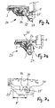
- Figur 3a
- eine teilweise vergrößerte Detailansicht X des Schiebers in der Verriegelungsstellung,
- Figur 3b
- eine teilweise vergrößerte Detailansicht X des Schiebers in einer Entriegelungsstellung,
- Figur 4a
- eine teilweise Detaildarstellung Y des Schiebers im Bereich eines Festlegelementes in Klemmstellung desselben,
- Figur 4b
- eine teilweise Detaildarstellung Y des Schiebers im Bereich einer Festlegelementes in Nichtklemmstellung desselben,
Figur 5- eine Seitenansicht der Aufnahmeeinrichtung mit einer Leuchteinheit in einer der Einschubstellung nahen Lage,
Figur 6- eine Seitenansicht der Aufnahmeeinrichtung mit einer Leuchteinheit in einer Einschubstellung und in einer Kippstellung,
- Figur 7a
- eine Detailansicht Y in
Figur 5 - Figur 7b
- eine Detailansicht Y in
Figur 5 - Figur 7c
- ein schematischer Vertikalschnitt durch die Kippeinheit.
- FIG. 1
- a rear view of a receiving device (front end module) with a receiving trough for Aufnanme a lighting unit in a locking position of a slider,
- FIG. 2
- a rear view of a receiving device (front end module) with a receiving trough for receiving a lighting unit in an unlocked position of the slider,
- FIG. 3a
- a partially enlarged detail view X of the slider in the locking position,
- FIG. 3b
- a partially enlarged detail view X of the slider in an unlocked position,
- FIG. 4a
- a partial detail representation Y of the slider in the region of a fixed element in clamping position thereof,
- FIG. 4b
- a partial detail representation Y of the slider in the region of a fixed element in the non-clamping position of the same,
- FIG. 5
- a side view of the receiving device with a light unit in a position close to the insertion position,
- FIG. 6
- a side view of the receiving device with a lighting unit in an insertion position and in a tilted position,
- Figure 7a
- a detailed view Y in
FIG. 5 a tilting unit of the fastening device in a disengaged position hinge elements of the lighting unit and the receiving device, - FIG. 7b
- a detailed view Y in
FIG. 5 a tilting unit of the fastening device in an engaged position of hinge elements of the lighting unit and the receiving device, and - FIG. 7c
- a schematic vertical section through the tilting unit.
Eine Aufnahmeeinrichtung 1 kann als ein Frontendmodul ausgebildet sein, das über Montageträger an einer Karosserie des Kraftfahrzeuges befestigbar ist. Alternativ kann die Aufnahmeeinrichtung 1 auch Bestandteil der Karosserie des Fahrzeugs sein. Die Aufnahmeeinrichtung 1 weist eine Aufnahmemulde 2 zur lösbaren Befestigung einer Leuchteinheit 3 auf. Wie aus den
Die erfindungsgemäße Befestigungsvorrichtung weist zum einen eine Schiebe-/Rasteinheit 4 auf, die an einer Rückseite 5 der Aufnahmeeinrichtung 1 angeordnet ist. Die Schiebe-/Rasteinheit 4 weist einen geradlinigen Schieber 6 auf, der in einem durch an der Rückseite 5 der Aufnahmeeinrichtung 1 angeformte Laschen 7 gebildeten Schlitz längsverschieblich gelagert ist. Der Schieber 6 ist entlang eines senkrecht zu einer Fahrzeuglängsachse verlaufenden Schiebeweges 8 linear beweglich angeordnet. Der Schieber 6 weist mindestens ein Langloch 9 sowie zwei längs des Schiebers 6 beabstandet zueinander angeordnete Klemmelemente 10 auf. Die Klemmelemente 10 sind als Federelemente ausgebildet, die über zwei Federarme 11 verfügen, die quer zur Erstreckung des Schiebers 6 federnd angeordnet sind. In der gemäß
Durch Verschieben des Schiebers 6 entlang des Schiebeweges 8 in eine Entriegelungsstellung gemäß
Wie aus den
In dem Bereich eines Randes 18 der Aufnahmemulde 2 der Aufnahmeeinrichtung 1 bzw. einer Karosserieöffnung des Fahrzeugs ist eine Kippeinheit 20 vorgesehen, mittels derer die Leuchteinheit 3 nach Entriegeln unter Bewegung entlang der translatorischen Führungsbahn 14 um eine Schwenkachse 21 entlang einer rotatorischen Führungsbahn 22 in eine äußere Endstellung 23 bewegbar ist. In dieser äußeren Endstellung 23 ist die Leuchteinheit 3 geneigt an dem Rand 18 der Aufnahmeöffnung 19 gehalten, wobei die Rückseite 12 der Leuchteinheit 3 zugänglich ist zur Vornahme eines Leuchmittelwechsels.In the region of an edge 18 of the receiving
Die Kippeinheit 20 bildet eine Scharniereinheit, wobei ein gabelförmiges Scharnierelement 24 der Leuchteinheit 3 ein zylinderförmiges Scharnierelement 25 der Aufnahmeeinrichtung 1 in der Scharnierstellung der Aufnahmeeinrichtung 1 umgreift. Die Längsachse des Scharnierelementes 25 bildet somit die Schwenkachse 21, die windschief oder senkrecht zu der translatorischen Führungsbahn 14 und senkrecht zur Fahrzeuglängsachse verläuft. In der inneren Endstellung der Leuchteinheit 3 ist das Scharnierelement 24 der Leuchteinheit 3 in einem Abstand F zu dem Scharnierelement 25 der Aufnahmeeinrichtung 1 angeordnet. Dieser Abstand F entspricht der Länge der translatorischen Führungsbahn 14. Alternativ kann das zylinderförmige Scharnierelement 25 auch an dem Fortsatz 26 der Leuchteinheit 3 und das gabelförmige Scharnierelement 24 an der Aufnahmeeinheit 1 angeformt sein.The tilting
Wie besser aus den
Zum Verbringen der Leuchteinheit 3 aus der inneren Endstellung in die äußere Endstellung 23, in der die Leuchteinheit 3 geneigt unter Zugänglichkeit der Rückseite 12 derselben angeordnet ist, wird zuerst der Schieber 6 aus der Verriegelungsstellung in eine Entriegelungsstellung verbracht. Die Leuchteinheit 3 kann nun aus der inneren Endstellung in eine Zwischenstellung 31 verbracht werden, wobei die Leuchteinheit 3 entlang einer translatorischen Führungsbahn 14 geführt wird. Zur geführten translatorischen Bewegung der Leuchteinheit 3 weist die Aufnahmeeinrichtung 1 an Seitenwänden langgestreckte Rippen 32 auf, an denen Nasen 33 der Leuchteinheit 3 entlanggleiten. Sobald das Scharnierelement 25 der Aufnahmeeinrichtung 1 von dem Scharnierelement 24 der Leuchteinheit 3 erfasst wird (Scharnierstellung), ist die translatorische Bewegung beendet und die Leuchteinheit 3 befindet sich in einer aufrechten zwischenstellung 31. Durch Aufwenden einer in Axialrichtung der Leuchteinheit 3 wirkenden Kraft wird die Leuchteinheit 3 nun um die Schwenkachse 21 soweit verschwenkt, bis sie die äußere Endstellung 23 erreicht hat. Durch Öffnen einer rückseitig der Leuchteinheit 3 angeordneten Kappe kann nun das Leuchtmittel gewechselt werden. Die Scharniereinheit ist derart stabil ausgebildet, dass die Leuchteinheit 3 in dem gekippten Zustand gehalten werden kann. Vorteilhaft kann hierdurch ein Leuchtmittelwechsel in einer angenehmen Höhe der Leuchteinheit 3 erfolgen. Es ist sichergestellt, dass die Leuchteinheit 3 nicht selbsttätig von der Aufnahmeeinrichtung 1 entfernt werden kann.To bring the
Nach dem Leuchtmittelwechsel wird die Leuchteinheit 3 aus der äußeren Endstellung 23 in die Zwischenstellung 31 zurückgeschwenkt und nachfolgend entlang der translatorischen Führungsbahn 14 in die innere Endstellung verbracht. Durch nachfolgendes Verriegeln des Schiebers 8 ist die Leuchteinheit 3 wieder in der Aufnahmemulde 2 fixiert. Vorzugsweise weist die Leuchteinheit 3 von dem Gehäuse derselben rückseitig abragende Stifte auf, die in korrespondierende Aufnahmen an der Rückseite 5 der Aufnahmeeinrichtung 1 eingreifen. Die Aufnahmen können als Lochungen oder Ausnehmungen ausgebildet sein, die eine definierte Relativlage der Leuchteinheit 3 zu der Aufnahmeeinrichtung 1 ermöglichen.After changing the light source, the
Zur Montage der Leuchteinheit 3 kann diese unter I-neingriffbringen der korrespondierenden Scharnierelemente 24 der Leuchteinheit 3 und der Scharnierelemente 25 der Aufnahmeeinrichtung 1 angesetzt werden. Die Leuchteinheit 3 weist somit eine definierte Einsetzposition zu der Aufnahmeeinrichtung 1 auf. Nachfolgend kann - wie beim Leuchtmittelwechsel - die Leuchteinheit 3 durch Verschwenken entlang der rotatorischen Führungsbahn 22 und nachfolgendem Verschieben entlang der translatorischen Führungsbahn in die innere Endstellung verbracht werden, in der durch Verriegelungsmittel die Verriegelung der Leuchteinheit 3 erfolgt.For mounting the
Zur Erhöhung der Vibrationsfestigkeit der Leuchteinheit 3 in der inneren Endstellung derselben sind an der Rückseite 5 der Aufnahmeeinrichtung 1 mittels Verschraubung 41 zwei Befestigungslaschen 40 montiert. Die langgestreckten Befestigungslaschen 40 erstrecken sich im Wesentlichen in vertikaler Richtung bzw. in einem relativ kleinen spitzen Winkel zu einer vertikalen Ebene. Im vorliegenden Ausführungsbeispiel sind zwei Befestigungslaschen 40 vorgesehen, die in einem Abstand zueinander angeordnet sind.To increase the vibration resistance of the
Claims (13)
Applications Claiming Priority (1)
| Application Number | Priority Date | Filing Date | Title |
|---|---|---|---|
| DE102007062434A DE102007062434A1 (en) | 2007-12-20 | 2007-12-20 | Fastening device for a light unit and method for changing the bulb |
Publications (3)
| Publication Number | Publication Date |
|---|---|
| EP2072331A2 true EP2072331A2 (en) | 2009-06-24 |
| EP2072331A3 EP2072331A3 (en) | 2009-09-30 |
| EP2072331B1 EP2072331B1 (en) | 2015-02-11 |
Family
ID=40474686
Family Applications (1)
| Application Number | Title | Priority Date | Filing Date |
|---|---|---|---|
| EP08019451.7A Not-in-force EP2072331B1 (en) | 2007-12-20 | 2008-11-06 | Fixing device for a lighting unit and method of exchanging the bulb |
Country Status (2)
| Country | Link |
|---|---|
| EP (1) | EP2072331B1 (en) |
| DE (1) | DE102007062434A1 (en) |
Cited By (2)
| Publication number | Priority date | Publication date | Assignee | Title |
|---|---|---|---|---|
| DE102010021567A1 (en) * | 2010-05-26 | 2011-12-01 | Gm Global Technology Operations Llc (N.D.Ges.D. Staates Delaware) | Headlight arrangement for motor vehicle, has illuminating medium with headlight casing and with carrier structure |
| US10400977B2 (en) | 2017-02-27 | 2019-09-03 | Motor Coach Industries Limited | Quick adjust vehicle headlight assembly |
Families Citing this family (3)
| Publication number | Priority date | Publication date | Assignee | Title |
|---|---|---|---|---|
| DE102011011701A1 (en) * | 2011-02-18 | 2012-08-23 | Gm Global Technology Operations, Llc | Mounting bracket for mounting module of front headlight of motor vehicle, comprises receptacle recess for headlight, and pivot support for front headlight, which is engaged with one or multiple support elements |
| DE102011115797A1 (en) | 2011-10-11 | 2013-04-11 | Gm Global Technology Operations, Llc | Headlamp assembly of a vehicle with headlamp fixture |
| DE102022202836A1 (en) | 2022-03-23 | 2023-09-28 | Psa Automobiles Sa | Body part for accommodating an exterior lighting device of a vehicle as well as the exterior lighting device and a method for assembling the exterior lighting device |
Citations (5)
| Publication number | Priority date | Publication date | Assignee | Title |
|---|---|---|---|---|
| US5428511A (en) | 1994-09-29 | 1995-06-27 | General Motors Corporation | Quick release vehicle headlamp arrangement |
| DE4133002C3 (en) | 1991-10-04 | 1996-02-15 | Bayerische Motoren Werke Ag | Fastening device for a motor vehicle headlight assembly |
| EP1103417A1 (en) | 1999-11-29 | 2001-05-30 | Valeo Vision | Mobile lighting or signaling device for vehicle |
| EP1231107A1 (en) | 2001-02-08 | 2002-08-14 | Faurecia Industries | Headlamp unit for vehicle with improved headlamp fastening means |
| DE19741522C2 (en) | 1997-09-20 | 2002-08-22 | Bosch Gmbh Robert | Pre-assembled unit |
Family Cites Families (14)
| Publication number | Priority date | Publication date | Assignee | Title |
|---|---|---|---|---|
| JPH0329232Y2 (en) * | 1985-07-19 | 1991-06-21 | ||
| IT1232138B (en) * | 1989-07-07 | 1992-01-23 | Carello Spa | RECESSED PROJECTOR, PARTICULARLY FOR VEHICLES |
| DE4127716C1 (en) * | 1991-08-22 | 1992-06-17 | Mercedes-Benz Aktiengesellschaft, 7000 Stuttgart, De | Motor vehicle headlamp mounted above bumper - has hinged lever allowing pivoting outwards from bodywork recess for changing bulb |
| JPH06107060A (en) * | 1992-09-30 | 1994-04-19 | Mazda Motor Corp | Head lamp installation structure |
| DE4311419C2 (en) * | 1993-04-07 | 1995-09-07 | Porsche Ag | Fixing device for a headlight |
| US5420762A (en) * | 1993-09-24 | 1995-05-30 | Trw Inc. | Automotive headlamp assembly fastening system |
| DE4334721B4 (en) * | 1993-10-12 | 2005-06-23 | Automotive Lighting Reutlingen Gmbh | Headlights for vehicles |
| DE19741605B4 (en) * | 1996-09-27 | 2006-06-29 | Volkswagen Ag | Fastening device for a headlight on a motor vehicle |
| JP3443598B2 (en) * | 1997-10-22 | 2003-09-02 | 日野自動車株式会社 | Mounting structure of vehicle front lighting device |
| FR2785037B1 (en) * | 1998-10-21 | 2001-03-23 | Valeo Vision | LIGHTING OR SIGNALING DEVICE FOR A MOTOR VEHICLE, PARTICULARLY A SPOTLIGHT, EQUIPPED WITH NEW MEANS OF ACCESS TO A LAMP |
| JP3891007B2 (en) * | 2001-04-23 | 2007-03-07 | 日産自動車株式会社 | Front body structure of automobile and assembly method of front body |
| FR2833661B1 (en) * | 2001-12-19 | 2004-08-13 | Renault | ATTACHMENT DEVICE FOR A PARTICULARLY AUTOMOTIVE ACCESSORY, IN PARTICULAR A SIGNAL LIGHT |
| JP2004314873A (en) * | 2003-04-18 | 2004-11-11 | Toyota Motor Corp | Lamp mounting structure for vehicle |
| DE102006017166A1 (en) * | 2006-04-12 | 2007-10-18 | Hella Kgaa Hueck & Co. | Method for mounting a headlamp and fastening device |
-
2007
- 2007-12-20 DE DE102007062434A patent/DE102007062434A1/en not_active Withdrawn
-
2008
- 2008-11-06 EP EP08019451.7A patent/EP2072331B1/en not_active Not-in-force
Patent Citations (5)
| Publication number | Priority date | Publication date | Assignee | Title |
|---|---|---|---|---|
| DE4133002C3 (en) | 1991-10-04 | 1996-02-15 | Bayerische Motoren Werke Ag | Fastening device for a motor vehicle headlight assembly |
| US5428511A (en) | 1994-09-29 | 1995-06-27 | General Motors Corporation | Quick release vehicle headlamp arrangement |
| DE19741522C2 (en) | 1997-09-20 | 2002-08-22 | Bosch Gmbh Robert | Pre-assembled unit |
| EP1103417A1 (en) | 1999-11-29 | 2001-05-30 | Valeo Vision | Mobile lighting or signaling device for vehicle |
| EP1231107A1 (en) | 2001-02-08 | 2002-08-14 | Faurecia Industries | Headlamp unit for vehicle with improved headlamp fastening means |
Cited By (2)
| Publication number | Priority date | Publication date | Assignee | Title |
|---|---|---|---|---|
| DE102010021567A1 (en) * | 2010-05-26 | 2011-12-01 | Gm Global Technology Operations Llc (N.D.Ges.D. Staates Delaware) | Headlight arrangement for motor vehicle, has illuminating medium with headlight casing and with carrier structure |
| US10400977B2 (en) | 2017-02-27 | 2019-09-03 | Motor Coach Industries Limited | Quick adjust vehicle headlight assembly |
Also Published As
| Publication number | Publication date |
|---|---|
| EP2072331A3 (en) | 2009-09-30 |
| EP2072331B1 (en) | 2015-02-11 |
| DE102007062434A1 (en) | 2009-06-25 |
Similar Documents
| Publication | Publication Date | Title |
|---|---|---|
| EP1780086B1 (en) | Device for the exact positioning and fastening of a bumper | |
| EP2152542B1 (en) | Front end module for vehicles | |
| DE2847908C3 (en) | Flashing lamp / headlamp mounting in motor vehicle bodies | |
| EP1912827B1 (en) | Device for the adjustable fixing of a headlamp | |
| EP2072331B1 (en) | Fixing device for a lighting unit and method of exchanging the bulb | |
| DE102009011708B4 (en) | vehicle light | |
| EP1871644B1 (en) | Motor vehicle headlamp provided with a removably mounted component | |
| EP2762390A1 (en) | Fastening device and alignment method for parts atttached to vehicles | |
| DE102006027460A1 (en) | Vehicle light unit fixing and adjusting device, has locking device with adjusting element as aligning unit which is supported on wall of holding device adjusted about adjusting path where adjusting element is regulated by latch element | |
| EP1645467A2 (en) | Fastening device for a lamp and assembly process | |
| EP1710122B1 (en) | Headlamp for vehicles | |
| DE102012200004B4 (en) | Headlight adjustment device | |
| DE19745928A1 (en) | Road vehicle door fixture | |
| DE102006018305A1 (en) | Headlamp for motor vehicle, has sliding unit that comprises clamping unit such that sliding unit is held in recess of support frame in drawing direction, which runs transverse to insertion direction using bayonet fixing | |
| DE102007062435B4 (en) | Fastening device for a light unit | |
| EP4382708A2 (en) | Guide arrangement for guiding at least one movable furniture part | |
| DE9312695U1 (en) | Adjustment arrangement for the pivotability of a reflector of a motor vehicle headlight | |
| EP1384622A1 (en) | Lighting unit and method for mounting a lighting unit | |
| DE102007026262A1 (en) | Illuminating device for vehicles, has guiding unit, which comprises linear guide medium, such that lamp is linearly guided between disassembly position and intermediate position | |
| DE102007024558A1 (en) | Headlight for motor vehicle, has adjustment element coupled to support frame by connecting rod at mounting point, and support frame guidably supported at another mounting point parallel to effective direction of adjustment element | |
| DE69005673T2 (en) | Headlights with adjustable beam angle. | |
| DE102005033114A1 (en) | Headlight for vehicle, has actuator with double sided adjusting element whereby first adjusting arm is protrude downwards by first face of actuator and second adjusting arm is protrude downwards by second face of actuator | |
| DE102008011718A1 (en) | Headlight for motor vehicle, has headlight housing with bag-like retaining recess into which deflection device is joined, so that shifting movement is enabled by joint connection between device and housing to create tolerance balancing | |
| DE102011000557B4 (en) | Adjustment device for headlights | |
| DE69935048T2 (en) | Coupling system for a headlight body with cover |
Legal Events
| Date | Code | Title | Description |
|---|---|---|---|
| PUAI | Public reference made under article 153(3) epc to a published international application that has entered the european phase |
Free format text: ORIGINAL CODE: 0009012 |
|
| AK | Designated contracting states |
Kind code of ref document: A2 Designated state(s): AT BE BG CH CY CZ DE DK EE ES FI FR GB GR HR HU IE IS IT LI LT LU LV MC MT NL NO PL PT RO SE SI SK TR |
|
| AX | Request for extension of the european patent |
Extension state: AL BA MK RS |
|
| PUAL | Search report despatched |
Free format text: ORIGINAL CODE: 0009013 |
|
| AK | Designated contracting states |
Kind code of ref document: A3 Designated state(s): AT BE BG CH CY CZ DE DK EE ES FI FR GB GR HR HU IE IS IT LI LT LU LV MC MT NL NO PL PT RO SE SI SK TR |
|
| AX | Request for extension of the european patent |
Extension state: AL BA MK RS |
|
| 17P | Request for examination filed |
Effective date: 20100315 |
|
| 17Q | First examination report despatched |
Effective date: 20100412 |
|
| AKX | Designation fees paid |
Designated state(s): AT BE BG CH CY CZ DE DK EE ES FI FR GB GR HR HU IE IS IT LI LT LU LV MC MT NL NO PL PT RO SE SI SK TR |
|
| GRAP | Despatch of communication of intention to grant a patent |
Free format text: ORIGINAL CODE: EPIDOSNIGR1 |
|
| INTG | Intention to grant announced |
Effective date: 20140915 |
|
| GRAS | Grant fee paid |
Free format text: ORIGINAL CODE: EPIDOSNIGR3 |
|
| GRAA | (expected) grant |
Free format text: ORIGINAL CODE: 0009210 |
|
| AK | Designated contracting states |
Kind code of ref document: B1 Designated state(s): AT BE BG CH CY CZ DE DK EE ES FI FR GB GR HR HU IE IS IT LI LT LU LV MC MT NL NO PL PT RO SE SI SK TR |
|
| REG | Reference to a national code |
Ref country code: GB Ref legal event code: FG4D Free format text: NOT ENGLISH |
|
| REG | Reference to a national code |
Ref country code: CH Ref legal event code: EP |
|
| REG | Reference to a national code |
Ref country code: IE Ref legal event code: FG4D Free format text: LANGUAGE OF EP DOCUMENT: GERMAN |
|
| REG | Reference to a national code |
Ref country code: AT Ref legal event code: REF Ref document number: 709808 Country of ref document: AT Kind code of ref document: T Effective date: 20150315 |
|
| REG | Reference to a national code |
Ref country code: DE Ref legal event code: R096 Ref document number: 502008012658 Country of ref document: DE Effective date: 20150326 |
|
| REG | Reference to a national code |
Ref country code: DE Ref legal event code: R081 Ref document number: 502008012658 Country of ref document: DE Owner name: HELLA KGAA HUECK & CO., DE Free format text: FORMER OWNER: HELLA AUTOTECHNIK SPOL. S.R.O., HELLA KGAA HUECK & CO., , CZ Ref country code: DE Ref legal event code: R081 Ref document number: 502008012658 Country of ref document: DE Owner name: HELLA AUTOTECHNIK NOVA, S.R.O., CZ Free format text: FORMER OWNER: HELLA AUTOTECHNIK SPOL. S.R.O., HELLA KGAA HUECK & CO., , CZ Ref country code: DE Ref legal event code: R081 Ref document number: 502008012658 Country of ref document: DE Owner name: HELLA AUTOTECHNIK NOVA, S.R.O., CZ Free format text: FORMER OWNERS: HELLA AUTOTECHNIK SPOL. S.R.O., MOHELNICE, CZ; HELLA KGAA HUECK & CO., 59557 LIPPSTADT, DE Ref country code: DE Ref legal event code: R081 Ref document number: 502008012658 Country of ref document: DE Owner name: HELLA KGAA HUECK & CO., DE Free format text: FORMER OWNERS: HELLA AUTOTECHNIK SPOL. S.R.O., MOHELNICE, CZ; HELLA KGAA HUECK & CO., 59557 LIPPSTADT, DE Ref country code: DE Ref legal event code: R081 Ref document number: 502008012658 Country of ref document: DE Owner name: HELLA GMBH & CO. KGAA, DE Free format text: FORMER OWNERS: HELLA AUTOTECHNIK SPOL. S.R.O., MOHELNICE, CZ; HELLA KGAA HUECK & CO., 59557 LIPPSTADT, DE |
|
| REG | Reference to a national code |
Ref country code: NL Ref legal event code: VDEP Effective date: 20150211 |
|
| RAP2 | Party data changed (patent owner data changed or rights of a patent transferred) |
Owner name: HELLA AUTOTECHNIK NOVA, S.R.O. Owner name: HELLA KGAA HUECK & CO. |
|
| REG | Reference to a national code |
Ref country code: LT Ref legal event code: MG4D |
|
| PG25 | Lapsed in a contracting state [announced via postgrant information from national office to epo] |
Ref country code: HR Free format text: LAPSE BECAUSE OF FAILURE TO SUBMIT A TRANSLATION OF THE DESCRIPTION OR TO PAY THE FEE WITHIN THE PRESCRIBED TIME-LIMIT Effective date: 20150211 Ref country code: SE Free format text: LAPSE BECAUSE OF FAILURE TO SUBMIT A TRANSLATION OF THE DESCRIPTION OR TO PAY THE FEE WITHIN THE PRESCRIBED TIME-LIMIT Effective date: 20150211 Ref country code: NO Free format text: LAPSE BECAUSE OF FAILURE TO SUBMIT A TRANSLATION OF THE DESCRIPTION OR TO PAY THE FEE WITHIN THE PRESCRIBED TIME-LIMIT Effective date: 20150511 Ref country code: ES Free format text: LAPSE BECAUSE OF FAILURE TO SUBMIT A TRANSLATION OF THE DESCRIPTION OR TO PAY THE FEE WITHIN THE PRESCRIBED TIME-LIMIT Effective date: 20150211 Ref country code: LT Free format text: LAPSE BECAUSE OF FAILURE TO SUBMIT A TRANSLATION OF THE DESCRIPTION OR TO PAY THE FEE WITHIN THE PRESCRIBED TIME-LIMIT Effective date: 20150211 Ref country code: FI Free format text: LAPSE BECAUSE OF FAILURE TO SUBMIT A TRANSLATION OF THE DESCRIPTION OR TO PAY THE FEE WITHIN THE PRESCRIBED TIME-LIMIT Effective date: 20150211 |
|
| PG25 | Lapsed in a contracting state [announced via postgrant information from national office to epo] |
Ref country code: IS Free format text: LAPSE BECAUSE OF FAILURE TO SUBMIT A TRANSLATION OF THE DESCRIPTION OR TO PAY THE FEE WITHIN THE PRESCRIBED TIME-LIMIT Effective date: 20150611 Ref country code: NL Free format text: LAPSE BECAUSE OF FAILURE TO SUBMIT A TRANSLATION OF THE DESCRIPTION OR TO PAY THE FEE WITHIN THE PRESCRIBED TIME-LIMIT Effective date: 20150211 Ref country code: GR Free format text: LAPSE BECAUSE OF FAILURE TO SUBMIT A TRANSLATION OF THE DESCRIPTION OR TO PAY THE FEE WITHIN THE PRESCRIBED TIME-LIMIT Effective date: 20150512 Ref country code: LV Free format text: LAPSE BECAUSE OF FAILURE TO SUBMIT A TRANSLATION OF THE DESCRIPTION OR TO PAY THE FEE WITHIN THE PRESCRIBED TIME-LIMIT Effective date: 20150211 |
|
| PG25 | Lapsed in a contracting state [announced via postgrant information from national office to epo] |
Ref country code: DK Free format text: LAPSE BECAUSE OF FAILURE TO SUBMIT A TRANSLATION OF THE DESCRIPTION OR TO PAY THE FEE WITHIN THE PRESCRIBED TIME-LIMIT Effective date: 20150211 Ref country code: EE Free format text: LAPSE BECAUSE OF FAILURE TO SUBMIT A TRANSLATION OF THE DESCRIPTION OR TO PAY THE FEE WITHIN THE PRESCRIBED TIME-LIMIT Effective date: 20150211 Ref country code: RO Free format text: LAPSE BECAUSE OF FAILURE TO SUBMIT A TRANSLATION OF THE DESCRIPTION OR TO PAY THE FEE WITHIN THE PRESCRIBED TIME-LIMIT Effective date: 20150211 Ref country code: SK Free format text: LAPSE BECAUSE OF FAILURE TO SUBMIT A TRANSLATION OF THE DESCRIPTION OR TO PAY THE FEE WITHIN THE PRESCRIBED TIME-LIMIT Effective date: 20150211 |
|
| REG | Reference to a national code |
Ref country code: DE Ref legal event code: R097 Ref document number: 502008012658 Country of ref document: DE |
|
| REG | Reference to a national code |
Ref country code: FR Ref legal event code: PLFP Year of fee payment: 8 |
|
| PG25 | Lapsed in a contracting state [announced via postgrant information from national office to epo] |
Ref country code: PL Free format text: LAPSE BECAUSE OF FAILURE TO SUBMIT A TRANSLATION OF THE DESCRIPTION OR TO PAY THE FEE WITHIN THE PRESCRIBED TIME-LIMIT Effective date: 20150211 |
|
| PLBE | No opposition filed within time limit |
Free format text: ORIGINAL CODE: 0009261 |
|
| STAA | Information on the status of an ep patent application or granted ep patent |
Free format text: STATUS: NO OPPOSITION FILED WITHIN TIME LIMIT |
|
| PG25 | Lapsed in a contracting state [announced via postgrant information from national office to epo] |
Ref country code: IT Free format text: LAPSE BECAUSE OF FAILURE TO SUBMIT A TRANSLATION OF THE DESCRIPTION OR TO PAY THE FEE WITHIN THE PRESCRIBED TIME-LIMIT Effective date: 20150211 |
|
| 26N | No opposition filed |
Effective date: 20151112 |
|
| PGFP | Annual fee paid to national office [announced via postgrant information from national office to epo] |
Ref country code: GB Payment date: 20151123 Year of fee payment: 8 |
|
| PG25 | Lapsed in a contracting state [announced via postgrant information from national office to epo] |
Ref country code: SI Free format text: LAPSE BECAUSE OF FAILURE TO SUBMIT A TRANSLATION OF THE DESCRIPTION OR TO PAY THE FEE WITHIN THE PRESCRIBED TIME-LIMIT Effective date: 20150211 |
|
| PG25 | Lapsed in a contracting state [announced via postgrant information from national office to epo] |
Ref country code: LU Free format text: LAPSE BECAUSE OF FAILURE TO SUBMIT A TRANSLATION OF THE DESCRIPTION OR TO PAY THE FEE WITHIN THE PRESCRIBED TIME-LIMIT Effective date: 20151106 Ref country code: MC Free format text: LAPSE BECAUSE OF FAILURE TO SUBMIT A TRANSLATION OF THE DESCRIPTION OR TO PAY THE FEE WITHIN THE PRESCRIBED TIME-LIMIT Effective date: 20150211 |
|
| REG | Reference to a national code |
Ref country code: CH Ref legal event code: PL |
|
| PG25 | Lapsed in a contracting state [announced via postgrant information from national office to epo] |
Ref country code: LI Free format text: LAPSE BECAUSE OF NON-PAYMENT OF DUE FEES Effective date: 20151130 Ref country code: CH Free format text: LAPSE BECAUSE OF NON-PAYMENT OF DUE FEES Effective date: 20151130 |
|
| REG | Reference to a national code |
Ref country code: IE Ref legal event code: MM4A |
|
| PG25 | Lapsed in a contracting state [announced via postgrant information from national office to epo] |
Ref country code: IE Free format text: LAPSE BECAUSE OF NON-PAYMENT OF DUE FEES Effective date: 20151106 |
|
| REG | Reference to a national code |
Ref country code: FR Ref legal event code: PLFP Year of fee payment: 9 |
|
| REG | Reference to a national code |
Ref country code: AT Ref legal event code: PC Ref document number: 709808 Country of ref document: AT Kind code of ref document: T Owner name: HELLA AUTOTECHNIK NOVA. S.R.O., CZ Effective date: 20161018 Ref country code: AT Ref legal event code: PC Ref document number: 709808 Country of ref document: AT Kind code of ref document: T Owner name: HELLA KGAA HUECK & CO., DE Effective date: 20161018 |
|
| PGFP | Annual fee paid to national office [announced via postgrant information from national office to epo] |
Ref country code: CZ Payment date: 20161026 Year of fee payment: 9 Ref country code: FR Payment date: 20161124 Year of fee payment: 9 Ref country code: DE Payment date: 20161110 Year of fee payment: 9 |
|
| PGFP | Annual fee paid to national office [announced via postgrant information from national office to epo] |
Ref country code: AT Payment date: 20161122 Year of fee payment: 9 |
|
| PG25 | Lapsed in a contracting state [announced via postgrant information from national office to epo] |
Ref country code: HU Free format text: LAPSE BECAUSE OF FAILURE TO SUBMIT A TRANSLATION OF THE DESCRIPTION OR TO PAY THE FEE WITHIN THE PRESCRIBED TIME-LIMIT; INVALID AB INITIO Effective date: 20081106 Ref country code: BG Free format text: LAPSE BECAUSE OF FAILURE TO SUBMIT A TRANSLATION OF THE DESCRIPTION OR TO PAY THE FEE WITHIN THE PRESCRIBED TIME-LIMIT Effective date: 20150211 |
|
| PG25 | Lapsed in a contracting state [announced via postgrant information from national office to epo] |
Ref country code: CY Free format text: LAPSE BECAUSE OF FAILURE TO SUBMIT A TRANSLATION OF THE DESCRIPTION OR TO PAY THE FEE WITHIN THE PRESCRIBED TIME-LIMIT Effective date: 20150211 |
|
| GBPC | Gb: european patent ceased through non-payment of renewal fee |
Effective date: 20161106 |
|
| PG25 | Lapsed in a contracting state [announced via postgrant information from national office to epo] |
Ref country code: BE Free format text: LAPSE BECAUSE OF NON-PAYMENT OF DUE FEES Effective date: 20151130 |
|
| PG25 | Lapsed in a contracting state [announced via postgrant information from national office to epo] |
Ref country code: MT Free format text: LAPSE BECAUSE OF FAILURE TO SUBMIT A TRANSLATION OF THE DESCRIPTION OR TO PAY THE FEE WITHIN THE PRESCRIBED TIME-LIMIT Effective date: 20150211 Ref country code: TR Free format text: LAPSE BECAUSE OF FAILURE TO SUBMIT A TRANSLATION OF THE DESCRIPTION OR TO PAY THE FEE WITHIN THE PRESCRIBED TIME-LIMIT Effective date: 20150211 |
|
| PG25 | Lapsed in a contracting state [announced via postgrant information from national office to epo] |
Ref country code: GB Free format text: LAPSE BECAUSE OF NON-PAYMENT OF DUE FEES Effective date: 20161106 |
|
| REG | Reference to a national code |
Ref country code: DE Ref legal event code: R082 Ref document number: 502008012658 Country of ref document: DE Representative=s name: PATENTANWAELTE FIEDLER, OSTERMANN & SCHNEIDER, DE Ref country code: DE Ref legal event code: R081 Ref document number: 502008012658 Country of ref document: DE Owner name: HELLA GMBH & CO. KGAA, DE Free format text: FORMER OWNERS: HELLA AUTOTECHNIK NOVA, S.R.O., MOHELNICE, CZ; HELLA KGAA HUECK & CO., 59557 LIPPSTADT, DE Ref country code: DE Ref legal event code: R081 Ref document number: 502008012658 Country of ref document: DE Owner name: HELLA AUTOTECHNIK NOVA, S.R.O., CZ Free format text: FORMER OWNERS: HELLA AUTOTECHNIK NOVA, S.R.O., MOHELNICE, CZ; HELLA KGAA HUECK & CO., 59557 LIPPSTADT, DE |
|
| REG | Reference to a national code |
Ref country code: DE Ref legal event code: R119 Ref document number: 502008012658 Country of ref document: DE |
|
| PG25 | Lapsed in a contracting state [announced via postgrant information from national office to epo] |
Ref country code: PT Free format text: LAPSE BECAUSE OF FAILURE TO SUBMIT A TRANSLATION OF THE DESCRIPTION OR TO PAY THE FEE WITHIN THE PRESCRIBED TIME-LIMIT Effective date: 20150211 |
|
| REG | Reference to a national code |
Ref country code: AT Ref legal event code: MM01 Ref document number: 709808 Country of ref document: AT Kind code of ref document: T Effective date: 20171106 |
|
| PG25 | Lapsed in a contracting state [announced via postgrant information from national office to epo] |
Ref country code: CZ Free format text: LAPSE BECAUSE OF NON-PAYMENT OF DUE FEES Effective date: 20171106 |
|
| PG25 | Lapsed in a contracting state [announced via postgrant information from national office to epo] |
Ref country code: AT Free format text: LAPSE BECAUSE OF NON-PAYMENT OF DUE FEES Effective date: 20171106 |
|
| REG | Reference to a national code |
Ref country code: FR Ref legal event code: ST Effective date: 20180731 |
|
| PG25 | Lapsed in a contracting state [announced via postgrant information from national office to epo] |
Ref country code: FR Free format text: LAPSE BECAUSE OF NON-PAYMENT OF DUE FEES Effective date: 20171130 Ref country code: DE Free format text: LAPSE BECAUSE OF NON-PAYMENT OF DUE FEES Effective date: 20180602 |