EP2072175A1 - Laser working apparatus - Google Patents
Laser working apparatus Download PDFInfo
- Publication number
- EP2072175A1 EP2072175A1 EP07829589A EP07829589A EP2072175A1 EP 2072175 A1 EP2072175 A1 EP 2072175A1 EP 07829589 A EP07829589 A EP 07829589A EP 07829589 A EP07829589 A EP 07829589A EP 2072175 A1 EP2072175 A1 EP 2072175A1
- Authority
- EP
- European Patent Office
- Prior art keywords
- microdeformation
- lens
- shape
- laser
- lenses
- Prior art date
- Legal status (The legal status is an assumption and is not a legal conclusion. Google has not performed a legal analysis and makes no representation as to the accuracy of the status listed.)
- Withdrawn
Links
Images


Classifications
-
- B—PERFORMING OPERATIONS; TRANSPORTING
- B23—MACHINE TOOLS; METAL-WORKING NOT OTHERWISE PROVIDED FOR
- B23K—SOLDERING OR UNSOLDERING; WELDING; CLADDING OR PLATING BY SOLDERING OR WELDING; CUTTING BY APPLYING HEAT LOCALLY, e.g. FLAME CUTTING; WORKING BY LASER BEAM
- B23K26/00—Working by laser beam, e.g. welding, cutting or boring
- B23K26/02—Positioning or observing the workpiece, e.g. with respect to the point of impact; Aligning, aiming or focusing the laser beam
- B23K26/06—Shaping the laser beam, e.g. by masks or multi-focusing
- B23K26/073—Shaping the laser spot
-
- B—PERFORMING OPERATIONS; TRANSPORTING
- B23—MACHINE TOOLS; METAL-WORKING NOT OTHERWISE PROVIDED FOR
- B23K—SOLDERING OR UNSOLDERING; WELDING; CLADDING OR PLATING BY SOLDERING OR WELDING; CUTTING BY APPLYING HEAT LOCALLY, e.g. FLAME CUTTING; WORKING BY LASER BEAM
- B23K26/00—Working by laser beam, e.g. welding, cutting or boring
- B23K26/02—Positioning or observing the workpiece, e.g. with respect to the point of impact; Aligning, aiming or focusing the laser beam
- B23K26/03—Observing, e.g. monitoring, the workpiece
- B23K26/032—Observing, e.g. monitoring, the workpiece using optical means
-
- B—PERFORMING OPERATIONS; TRANSPORTING
- B23—MACHINE TOOLS; METAL-WORKING NOT OTHERWISE PROVIDED FOR
- B23K—SOLDERING OR UNSOLDERING; WELDING; CLADDING OR PLATING BY SOLDERING OR WELDING; CUTTING BY APPLYING HEAT LOCALLY, e.g. FLAME CUTTING; WORKING BY LASER BEAM
- B23K26/00—Working by laser beam, e.g. welding, cutting or boring
- B23K26/02—Positioning or observing the workpiece, e.g. with respect to the point of impact; Aligning, aiming or focusing the laser beam
- B23K26/04—Automatically aligning, aiming or focusing the laser beam, e.g. using the back-scattered light
- B23K26/046—Automatically focusing the laser beam
-
- B—PERFORMING OPERATIONS; TRANSPORTING
- B23—MACHINE TOOLS; METAL-WORKING NOT OTHERWISE PROVIDED FOR
- B23K—SOLDERING OR UNSOLDERING; WELDING; CLADDING OR PLATING BY SOLDERING OR WELDING; CUTTING BY APPLYING HEAT LOCALLY, e.g. FLAME CUTTING; WORKING BY LASER BEAM
- B23K26/00—Working by laser beam, e.g. welding, cutting or boring
- B23K26/02—Positioning or observing the workpiece, e.g. with respect to the point of impact; Aligning, aiming or focusing the laser beam
- B23K26/06—Shaping the laser beam, e.g. by masks or multi-focusing
- B23K26/064—Shaping the laser beam, e.g. by masks or multi-focusing by means of optical elements, e.g. lenses, mirrors or prisms
-
- B—PERFORMING OPERATIONS; TRANSPORTING
- B23—MACHINE TOOLS; METAL-WORKING NOT OTHERWISE PROVIDED FOR
- B23K—SOLDERING OR UNSOLDERING; WELDING; CLADDING OR PLATING BY SOLDERING OR WELDING; CUTTING BY APPLYING HEAT LOCALLY, e.g. FLAME CUTTING; WORKING BY LASER BEAM
- B23K26/00—Working by laser beam, e.g. welding, cutting or boring
- B23K26/02—Positioning or observing the workpiece, e.g. with respect to the point of impact; Aligning, aiming or focusing the laser beam
- B23K26/06—Shaping the laser beam, e.g. by masks or multi-focusing
- B23K26/064—Shaping the laser beam, e.g. by masks or multi-focusing by means of optical elements, e.g. lenses, mirrors or prisms
- B23K26/0648—Shaping the laser beam, e.g. by masks or multi-focusing by means of optical elements, e.g. lenses, mirrors or prisms comprising lenses
-
- B—PERFORMING OPERATIONS; TRANSPORTING
- B23—MACHINE TOOLS; METAL-WORKING NOT OTHERWISE PROVIDED FOR
- B23K—SOLDERING OR UNSOLDERING; WELDING; CLADDING OR PLATING BY SOLDERING OR WELDING; CUTTING BY APPLYING HEAT LOCALLY, e.g. FLAME CUTTING; WORKING BY LASER BEAM
- B23K26/00—Working by laser beam, e.g. welding, cutting or boring
- B23K26/02—Positioning or observing the workpiece, e.g. with respect to the point of impact; Aligning, aiming or focusing the laser beam
- B23K26/06—Shaping the laser beam, e.g. by masks or multi-focusing
- B23K26/0665—Shaping the laser beam, e.g. by masks or multi-focusing by beam condensation on the workpiece, e.g. for focusing
Definitions
- the present invention relates to a laser processing apparatus which performs a processing by irradiating a laser beam emitted from a laser oscillator onto a surface of a workpiece through a condenser lens which condenses the laser beam on the workpiece.
- Patent Reference 1 Japanese Patent Application Kokai Publication No. 2006-7257
- Patent Reference 1 there are no drawings illustrating the detailed structure of the microdeformation mirrors, but there is a description of a structure wherein electrodes serving as about 40 actuators are covered with a transparent film formed by coating, and the transparent film is caused to undergo microdeformation due to an electric drag force generated by the actuators.
- the problems which the present invention aims to solve are: (1) In the method whereby 2 or more lenses are moved by means of a moving mechanism when changing a laser beam to a desired size and shape, there is a limit to the speed at which it is capable of responding to rapidly change to the desired beam shape; and (2) In the method whereby the microdeformation mirrors are deformed by means of actuators, discontinuities readily arise in laser beam intensity distribution.
- the laser processing apparatus of the present invention performs a processing by irradiating a laser beam emitted from a laser oscillator onto a surface of a workpiece through a condenser lens so as to rapidly change to the desired beam shape on a smooth curved surface.
- the apparatus comprises at least one microdeformation lens which changes the beam shape of the laser beam, and a lens deformation control device for controlling the amount of deformation of the at least one microdeformation lens in order to change the beam shape of the laser beam to a predetermined shape.
- the microdeformation lenses have a structure such that they can be caused to change to the predetermined shape by means of a plurality of actuators disposed around the outer periphery of the lenses.
- Control of the amount of microdeformation in the microdeformation lenses of the laser processing apparatus of the present invention is accomplished by controlling the operating position and/or the operating amount of the plurality of actuators.
- the laser processing apparatus of the present invention further comprises a processing distance measurement device for measuring the distance from the condenser lens to the workpiece.
- a processing distance measurement device for measuring the distance from the condenser lens to the workpiece.
- the focal point position is corrected, while maintaining the laser beam shape after being changed to a predetermined shape by the first microdeformation lens and/or the second microdeformation lens, by controlling the amount of deformation of the first microdeformation lens and the second microdeformation lens according to the distance from the condenser lens to the workpiece, measured by the processing distance measuring device, thereby making it possible to accurately adjust to changes in focal point position according to the distance from the workpiece.
- the curved surfaces of the lenses during deformation of the microdeformation lenses are smooth curved surfaces equivalent to ordinary lenses, it becomes possible to reduce discontinuities in laser intensity distribution, thereby making it possible to reduce processing flaws in the workpiece and to achieve high-precision processing.
- it is possible to rapidly change the laser beam to the desired beam shape it is also possible to apply it to cases where processing of a workpiece is to be performed at high speeds.
- the present invention achieves its objective of rapidly changing to the desired beam shape on a smooth curved surface by means of the following constitution.
- the present invention changes the shape of microdeformation lenses which change the beam shape of the laser beam shape to the desired shape by controlling the operating position and/or the operating amount of a plurality of actuators disposed around the outer periphery of the lenses.
- FIG. 1 is a diagram illustrating an example of the basic structure of a laser processing apparatus of the present invention.
- FIG. 2 is a basic structural diagram for when a beam shape is changed.
- FIG. 3 is an applied structural diagram for when a beam shape is changed.
- FIG. 4 is a diagram illustrating the focal point position during processing.
- FIG. 5 and FIG. 6 are schematic diagrams illustrating other examples of a laser processing apparatus of the present invention.
- FIG. 1 illustrates an example of a laser processing apparatus of the present invention when removing a metal layer formed on the surface of a workpiece 1 such as a substrate.
- Reference Numeral 2 is a laser beam emitted, for example, from a YAG laser oscillator (referred to below simply as a laser oscillator), having a wavelength and intensity at least one of which is set suitable for removing a metal layer.
- the laser beam 2 emitted from this laser oscillator is irradiated onto the surface of the workpiece 1, through a condenser lens 3, to remove the metal layer.
- two microdeformation lenses 4 and 5 are arranged to change the beam shape in the X (horizontal) and Y (vertical) directions, for example, in an optical path between the laser oscillator and the condenser lens 3. Moreover, the amount of deformation of these two microdeformation lenses 4 and 5 is controlled by a lens deformation control device 6.
- the microdeformation lenses 4 and 5 have a structure such that a plurality of actuators (such as piezoelectric elements) 4b and 5b are disposed around the outer periphery of commercially available lenses (BK7 glass, quartz glass, etc.) 4a and 5a at predetermined intervals (e.g., equal intervals).
- actuators such as piezoelectric elements
- the lens deformation control device 6 determines at what operating amount to operate which actuators 4b and 5b, according to the change in beam shape, so as to change the lenses 4a and 5a to the desired shape, thereby changing the beam shape.
- the lenses 4a and 5a it is possible to subject the lenses 4a and 5a to microdeformation by arranging at least two actuators 4b and 5b, as shown in FIG. 2 . It is also possible to subject the lenses 4a and 5a to microdeformation in any direction at high speed, if the actuators 4b and 5b are arranged so as to encompass the outer periphery of the lenses 4a and 5a, as shown in FIG. 3 .
- Such microdeformation lenses 4 and 5 are designed so that the lenses 4a and 5a can be changed to the desired shape at higher speeds than in conventional cases where lenses are operated mechanically. Furthermore, the curved surfaces of the lenses are smoother after deformation than in methods where deformation is performed with actuators from behind the mirrors, since the shape of the lenses 4a and 5a is adjusted by the actuators 4b and 5b which encompass the outer periphery of the lenses 4a and 5a. Moreover, it is possible to observe the state of laser processing while laser the processing is being performed, since transmitted light can be utilized.
- the laser processing apparatus of the present invention is able to adapt to such changes in the focal point position, by mutually changing the shape of the two microdeformation lenses 4 and 5 shown in FIG. 1 .
- the focal point position of the laser beam 2 with a circular cross section shown in FIG. 4 (a) when the laser beam 2 has an elliptical cross section with a vertical main axis shown in FIG. 4 (b) , the focal point position shortens, as shown by the broken line.
- the distance from the condenser lens 3 to the workpiece is measured with a processing distance measurement device (CCD camera for observation) 7 installed on the rear surface side of the X-direction microdeformation lens 5, for example.
- the amount of deformation of the microdeformation lenses 4 and 5 is controlled in response to this measured distance, and the focal point position can be corrected while maintaining the shape of the changed laser beam 2.
- the focal point position changes according to the distance from the workpiece 1 and the angle of incidence.
- the amount of deformation of the microdeformation lenses 4 and 5 is controlled by utilizing the fact that the laser beam 2 arrives at the workpiece 1 in a straight line from the condenser lens 3.
- the amount of deformation is controlled by calculating the amount of correction of the focal point distance from the distance from the workpiece 1, by using the angle of incidence of the laser beam 2 and the position at which the laser beam 2 reaches the condenser lens 3 from galvanomirrors 8a and 8b disposed between the X-direction microdeformation lens 5 and the condenser lens 3. Consequently, high-precision processing is possible even with laser processing using diagonal irradiation.
- FIG. 5 (a) illustrates an example in which the laser irradiation position and the beam shape are controlled when an output signal is generated from the lens deformation control device 6 to the X and Y-direction microdeformation lenses 4 and 5, on the basis of input signals from the processing distance measurement device 7, which ascertains the laser irradiation position on the workpiece 1, and also observes whether a predetermined beam shape has been achieved.
- FIG. 5 (b) illustrates an example in which a CCD camera 9 for inspection is added to the rear surface side of the Y-direction microdeformation lens 4.
- the CCD camera 9 for inspection it becomes possible to examine whether only the metal material designated for processing has been processed, by detecting a characteristic flame reaction color for the metal material at the time of laser processing, for, instance, when only a specified metal material of the workpiece 1 is to be processed. Therefore, if the flame reaction color is not characteristic of the specified material, then it is conceivable that slippage of the processing position has occurred.
- the irradiation position of the laser beam 2 is corrected by generating an output signal from the lens deformation control device 6 to the X and Y-direction microdeformation lenses 4 and 5.
- FIG. 6 (a) shows the wave form of the laser beam 2 prior to reflection by the Y-direction microdeformation lens 4.
- FIG. 6 (c) shows the wave form of the laser beam 2 prior to passing through the X-direction microdeformation lens 5.
- FIG. 6 (d) shows the wave form of the laser beam 2 after passing through the condenser lens 3.
- the present invention is not limited to the above examples, and the embodiments can of course be suitably modified, as long as they are within the scope of the technical ideas recited in the claims.
- the operating position and the operating amount of the actuators are controlled together, but if it is possible to change to a predetermined shape, then only one of either of them may be controlled.
- processing is to be performed on only a limited area such as a junction to a substrate of an IC chip in electronic circuitry, it is possible to use one microdeformation lens in laser processing in which the beam shape of a laser beam is changed in only one direction.
- the structure of the apparatus of the present invention is not limited to the structures shown in FIG. 1 and FIG. 5 , but in the example shown in FIG. 5 (b) , for example, if the processing distance measurement device 7 is installed on the rear surface side of the Y-direction microdeformation lens 4, it is no longer possible to detect the beam shape since the beam is deformed by the X-direction microdeformation lens 5 at a later stage.
- the present invention can be used for laser processing such as thin-film removal, micromachining, and the like, as long as the processing requires the irradiation of a laser beam onto a workpiece.
Landscapes
- Physics & Mathematics (AREA)
- Optics & Photonics (AREA)
- Engineering & Computer Science (AREA)
- Plasma & Fusion (AREA)
- Mechanical Engineering (AREA)
- Laser Beam Processing (AREA)
Abstract
PROBLEM: To rapidly change to a desired beam shape on a smooth curved surface.
MEANS: A laser processing apparatus which performs a predetermined processing by irradiating a laser beam (2) emitted from a laser oscillator onto a surface of a workpiece (1) through a condenser lens (3). There are provided microdeformation lenses (4), (5) for changing the beam shape in the vertical direction and the horizontal direction in a laser beam (2), for example, and a lens deformation control device for controlling the amount of deformation of the microdeformation lenses (4), (5) which are to adjust the beam shape of the laser beam (2) to a predetermined shape. The microdeformation lenses (4), (5) have a structure such that they can be caused to change to a desired shape by means of a plurality of actuators (4b), (5b) disposed around the outer periphery of the lenses.
ADVANTAGEOUS EFFECTS: High-precision processing can be achieved, while maintaining the desired beam shape, even if the shape of the workpiece changes, since the laser beam shape can be rapidly changed to the desired shape, on a smooth curved surface equivalent to that of an ordinary lens.
Description
- The present invention relates to a laser processing apparatus which performs a processing by irradiating a laser beam emitted from a laser oscillator onto a surface of a workpiece through a condenser lens which condenses the laser beam on the workpiece.
- When using laser beams in the processing of a workpiece, it is a routine practice to change the laser beams to the desired size and shape according to the workpiece. A typical example of a specific method for changing the shape of laser beams involves changing the beam shape by moving 2 or more lenses.
- In this method, a mechanism is required for moving the lenses, but there is a limit to the speed at which such a lens-moving mechanism is capable of responding in cases where processing of a workpiece is to be performed at high speeds or in cases where adjustment change to the desired beam shape is to be made rapidly, thus resulting in the drawback that it cannot be used.
- Accordingly, in order to eliminate this drawback, a laser processing apparatus was disclosed which adjusts to the desired beam shape at high speeds by deforming microdeformation mirrors by means of actuators (e.g., Patent Reference 1).
Patent Reference 1: Japanese Patent Application Kokai Publication No.2006-7257 - In
Patent Reference 1, there are no drawings illustrating the detailed structure of the microdeformation mirrors, but there is a description of a structure wherein electrodes serving as about 40 actuators are covered with a transparent film formed by coating, and the transparent film is caused to undergo microdeformation due to an electric drag force generated by the actuators. - However, in the case of such microdeformation mirrors, since the mirror surface at the time of deformation does not form a smooth curved surface, but tends, rather, to form a pseudo-curved surface, it is thought that discontinuities readily arise in laser beam intensity distribution.
- The problems which the present invention aims to solve are: (1) In the method whereby 2 or more lenses are moved by means of a moving mechanism when changing a laser beam to a desired size and shape, there is a limit to the speed at which it is capable of responding to rapidly change to the desired beam shape; and (2) In the method whereby the microdeformation mirrors are deformed by means of actuators, discontinuities readily arise in laser beam intensity distribution.
- The laser processing apparatus of the present invention performs a processing by irradiating a laser beam emitted from a laser oscillator onto a surface of a workpiece through a condenser lens so as to rapidly change to the desired beam shape on a smooth curved surface. The apparatus comprises at least one microdeformation lens which changes the beam shape of the laser beam, and a lens deformation control device for controlling the amount of deformation of the at least one microdeformation lens in order to change the beam shape of the laser beam to a predetermined shape. The microdeformation lenses have a structure such that they can be caused to change to the predetermined shape by means of a plurality of actuators disposed around the outer periphery of the lenses.
- Control of the amount of microdeformation in the microdeformation lenses of the laser processing apparatus of the present invention is accomplished by controlling the operating position and/or the operating amount of the plurality of actuators.
- The laser processing apparatus of the present invention further comprises a processing distance measurement device for measuring the distance from the condenser lens to the workpiece. There is a first microdeformation lens for changing the beam shape in one direction, and a second microdeformation lens for changing the beam shape in the other direction.
The focal point position is corrected, while maintaining the laser beam shape after being changed to a predetermined shape by the first microdeformation lens and/or the second microdeformation lens, by controlling the amount of deformation of the first microdeformation lens and the second microdeformation lens according to the distance from the condenser lens to the workpiece, measured by the processing distance measuring device, thereby making it possible to accurately adjust to changes in focal point position according to the distance from the workpiece. - In the present invention, due to the fact that the curved surfaces of the lenses during deformation of the microdeformation lenses are smooth curved surfaces equivalent to ordinary lenses, it becomes possible to reduce discontinuities in laser intensity distribution, thereby making it possible to reduce processing flaws in the workpiece and to achieve high-precision processing. In addition, since it is possible to rapidly change the laser beam to the desired beam shape, it is also possible to apply it to cases where processing of a workpiece is to be performed at high speeds.
-
-
FIG. 1 is a diagram illustrating an example of the basic structure of a laser processing apparatus of the present invention. -
FIG. 2 is a basic structural diagram for when a beam shape is changed, whereFIG. 2 (a) is a frontal view andFIG. 2 (b) is a side view. -
FIG. 3 is an applied structural diagram for when a beam shape is changed, whereFIG. 3 (a) is a frontal view andFIG. 3 (b) is a side view. -
FIG. 4 is a diagram illustrating the focal point position during processing, whereFIG. 4 (a) describes a typical focal point position,FIG. 4 (b) describes a focal point position after beam shape is changed, andFIG. 4 (c) describes a focal point position during actual processing. -
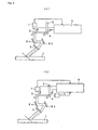
FIG. 5 (a) and (b) are schematic diagrams illustrating examples of the basic structure of another laser processing apparatus of the present invention. -
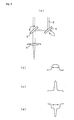
FIG. 6 (a) is a schematic diagram illustrating an example the basic structure of yet another laser processing apparatus of the present invention, andFIG. 6 (b)-(d) are diagrams of waveforms of laser beams at various positions. - 1 Workpiece
- 2
- Laser beam
- 3
- Condenser lens
- 4, 5
- Microdeformation lenses
- 4b, 5b
- Actuators
- 6
- Lens deformation control device
- 7
- Processing distance measurement device
- The present invention achieves its objective of rapidly changing to the desired beam shape on a smooth curved surface by means of the following constitution.
- The present invention changes the shape of microdeformation lenses which change the beam shape of the laser beam shape to the desired shape by controlling the operating position and/or the operating amount of a plurality of actuators disposed around the outer periphery of the lenses.
- A preferred embodiment of the present invention is described in detail with
FIGS. 1-6 with various embodiments of the invention.
FIG. 1 is a diagram illustrating an example of the basic structure of a laser processing apparatus of the present invention.FIG. 2 is a basic structural diagram for when a beam shape is changed.FIG. 3 is an applied structural diagram for when a beam shape is changed.FIG. 4 is a diagram illustrating the focal point position during processing.FIG. 5 andFIG. 6 are schematic diagrams illustrating other examples of a laser processing apparatus of the present invention. -
FIG. 1 illustrates an example of a laser processing apparatus of the present invention when removing a metal layer formed on the surface of aworkpiece 1 such as a substrate. - In
FIG. 1 ,Reference Numeral 2 is a laser beam emitted, for example, from a YAG laser oscillator (referred to below simply as a laser oscillator), having a wavelength and intensity at least one of which is set suitable for removing a metal layer. Thelaser beam 2 emitted from this laser oscillator is irradiated onto the surface of theworkpiece 1, through acondenser lens 3, to remove the metal layer. - In such a laser processing apparatus of the present invention, two
microdeformation lenses condenser lens 3. Moreover, the amount of deformation of these twomicrodeformation lenses deformation control device 6. - As shown in
FIG. 2 and FIG. 3 , themicrodeformation lenses - The lens
deformation control device 6 determines at what operating amount to operate which actuators 4b and 5b, according to the change in beam shape, so as to change the lenses 4a and 5a to the desired shape, thereby changing the beam shape. - In this case, it is possible to subject the lenses 4a and 5a to microdeformation by arranging at least two actuators 4b and 5b, as shown in
FIG. 2 . It is also possible to subject the lenses 4a and 5a to microdeformation in any direction at high speed, if the actuators 4b and 5b are arranged so as to encompass the outer periphery of the lenses 4a and 5a, as shown inFIG. 3 . -
Such microdeformation lenses - In the course of processing the
workpiece 1 with shape-changedlaser beam 2, slippage occurs in the focal point position when there are irregularities in the surface of the workpiece as shown inFIG. 1 . However, the laser processing apparatus of the present invention is able to adapt to such changes in the focal point position, by mutually changing the shape of the twomicrodeformation lenses FIG. 1 . - That is to say, in contrast to the focal point position of the
laser beam 2 with a circular cross section shown inFIG. 4 (a) , when thelaser beam 2 has an elliptical cross section with a vertical main axis shown inFIG. 4 (b) , the focal point position shortens, as shown by the broken line. - Therefore, it is possible to implement high-speed correction of the focal point position only, by moving the
condenser lens 3 as inFIG. 4 (c) , while maintaining the changed state of the beam shape such as inFIG. 4 (b) , for example, which was changed by means of a microdeformation lens 4 (the Y direction inFIG. 1 ). Accordingly, it is possible to adjust to changes the focal point position even when performing high-speed processing of theworkpiece 1. - When adjusting to changes in the focal point position, the distance from the
condenser lens 3 to the workpiece is measured with a processing distance measurement device (CCD camera for observation) 7 installed on the rear surface side of theX-direction microdeformation lens 5, for example. The amount of deformation of themicrodeformation lenses laser beam 2. - Moreover, when processing the
workpiece 1 by diagonally irradiating thelaser beam 2, as shown inFIG. 5 , the focal point position changes according to the distance from theworkpiece 1 and the angle of incidence. Accordingly, the amount of deformation of themicrodeformation lenses laser beam 2 arrives at theworkpiece 1 in a straight line from thecondenser lens 3. In other words, the amount of deformation is controlled by calculating the amount of correction of the focal point distance from the distance from theworkpiece 1, by using the angle of incidence of thelaser beam 2 and the position at which thelaser beam 2 reaches thecondenser lens 3 from galvanomirrors 8a and 8b disposed between theX-direction microdeformation lens 5 and thecondenser lens 3. Consequently, high-precision processing is possible even with laser processing using diagonal irradiation. -
FIG. 5 (a) illustrates an example in which the laser irradiation position and the beam shape are controlled when an output signal is generated from the lensdeformation control device 6 to the X and Y-direction microdeformation lenses distance measurement device 7, which ascertains the laser irradiation position on theworkpiece 1, and also observes whether a predetermined beam shape has been achieved. -
FIG. 5 (b) illustrates an example in which aCCD camera 9 for inspection is added to the rear surface side of the Y-direction microdeformation lens 4. In cases where theCCD camera 9 for inspection is added, it becomes possible to examine whether only the metal material designated for processing has been processed, by detecting a characteristic flame reaction color for the metal material at the time of laser processing, for, instance, when only a specified metal material of theworkpiece 1 is to be processed. Therefore, if the flame reaction color is not characteristic of the specified material, then it is conceivable that slippage of the processing position has occurred. Thus, as above, the irradiation position of thelaser beam 2 is corrected by generating an output signal from the lensdeformation control device 6 to the X and Y-direction microdeformation lenses - In an example where a laser beam is allowed to pass through a microdeformation lens, it is possible not only to directly observe the state of processing using the processing distance measurement device (CCD camera for observation) 7, but it is also possible to combine transmitted light (broken line) and reflected light (solid line) at the
X-direction microdeformation lens 5, as shown inFIG. 6 (a) . However, if transmitted light is used in theX-direction microdeformation lens 5, then it is not possible to change the beam shape in the X direction, and the beam shape is changed by using only the Y-direction microdeformation lens 4.FIG. 6 (b) shows the wave form of thelaser beam 2 prior to reflection by the Y-direction microdeformation lens 4.FIG. 6 (c) shows the wave form of thelaser beam 2 prior to passing through theX-direction microdeformation lens 5.FIG. 6 (d) shows the wave form of thelaser beam 2 after passing through thecondenser lens 3. - The present invention is not limited to the above examples, and the embodiments can of course be suitably modified, as long as they are within the scope of the technical ideas recited in the claims.
For example, in the above examples, the operating position and the operating amount of the actuators are controlled together, but if it is possible to change to a predetermined shape, then only one of either of them may be controlled. Moreover, if processing is to be performed on only a limited area such as a junction to a substrate of an IC chip in electronic circuitry, it is possible to use one microdeformation lens in laser processing in which the beam shape of a laser beam is changed in only one direction. - The structure of the apparatus of the present invention is not limited to the structures shown in
FIG. 1 andFIG. 5 , but in the example shown inFIG. 5 (b) , for example, if the processingdistance measurement device 7 is installed on the rear surface side of the Y-direction microdeformation lens 4, it is no longer possible to detect the beam shape since the beam is deformed by theX-direction microdeformation lens 5 at a later stage. - The present invention can be used for laser processing such as thin-film removal, micromachining, and the like, as long as the processing requires the irradiation of a laser beam onto a workpiece.
Claims (4)
- Laser processing apparatus which performs a processing by irradiating a laser beam emitted from a laser oscillator onto a surface of a workpiece through a condenser lens, comprising:at least one microdeformation lens which changes a beam shape of the laser beam;a lens deformation control device for controlling an amount of deformation of the at least one microdeformation lens in order to change the shape of the laser beam to a predetermined shape; anda plurality of actuators disposed around an outer periphery of the at least one microdeformation lens to change the shape of the at least one microdeformation lens to the predetermined shape.
- The laser processing apparatus according to claim 1, wherein control of an amount of deformation in the at least one microdeformation lens is accomplished by controlling an operating position and/or an operating amount of the plurality of actuators.
- The laser processing apparatus according to claim 1 or claim 2, wherein there are two microdeformation lenses consisting of a first microdeformation lens for changing the beam shape in one direction, and a second microdeformation lens for changing the beam shape in another direction.
- The laser processing apparatus according to claim 3, further comprising a processing distance measurement device for measuring a distance from the condenser lens to the workpiece, wherein a focal point position is corrected, while maintaining the laser beam shape which has been changed to the predetermined shape by the first microdeformation lens and/or the second microdeformation lens, by controlling the amount of deformation of the first microdeformation lens and the second microdeformation lens according to a distance from the condenser lens to the workpiece measured by this processing distance measurement device.
Applications Claiming Priority (2)
| Application Number | Priority Date | Filing Date | Title |
|---|---|---|---|
| JP2006279115A JP5242036B2 (en) | 2006-10-12 | 2006-10-12 | Laser processing equipment |
| PCT/JP2007/069851 WO2008047675A1 (en) | 2006-10-12 | 2007-10-11 | Laser working apparatus |
Publications (2)
| Publication Number | Publication Date |
|---|---|
| EP2072175A1 true EP2072175A1 (en) | 2009-06-24 |
| EP2072175A4 EP2072175A4 (en) | 2010-12-15 |
Family
ID=39313913
Family Applications (1)
| Application Number | Title | Priority Date | Filing Date |
|---|---|---|---|
| EP07829589A Withdrawn EP2072175A4 (en) | 2006-10-12 | 2007-10-11 | LASER MACHINING APPARATUS |
Country Status (6)
| Country | Link |
|---|---|
| US (1) | US8094350B2 (en) |
| EP (1) | EP2072175A4 (en) |
| JP (1) | JP5242036B2 (en) |
| KR (1) | KR20090079234A (en) |
| CN (1) | CN101522357A (en) |
| WO (1) | WO2008047675A1 (en) |
Families Citing this family (9)
| Publication number | Priority date | Publication date | Assignee | Title |
|---|---|---|---|---|
| JP5371514B2 (en) * | 2009-04-01 | 2013-12-18 | 株式会社日立ハイテクノロジーズ | Laser light state inspection method and apparatus, and solar panel manufacturing method |
| JP5536929B2 (en) * | 2013-04-22 | 2014-07-02 | 日本特殊陶業株式会社 | Glow plug manufacturing method |
| CN105983780A (en) * | 2015-03-06 | 2016-10-05 | 中国兵器装备研究院 | Method for heating metal material in additive manufacturing |
| US12544854B2 (en) | 2017-10-25 | 2026-02-10 | Nikon Corporation | Processing apparatus, processing system, and manufacturing method of movable body |
| WO2019082309A1 (en) * | 2017-10-25 | 2019-05-02 | 株式会社ニコン | Processing device, coating, processing method, and method for producing moving body |
| CN108957736B (en) * | 2018-07-25 | 2019-05-21 | 清华大学 | Mechanically actuated flexible zoom lens |
| EP3747588A1 (en) * | 2019-06-07 | 2020-12-09 | Bystronic Laser AG | Processing device for laser processing of a workpiece and method for laser processing of a workpiece |
| CN216990332U (en) * | 2021-06-15 | 2022-07-19 | 苏州创鑫激光科技有限公司 | A laser processing device |
| CN114951966A (en) * | 2022-05-30 | 2022-08-30 | 深圳华工新能源装备有限公司 | A method and system for automatic focus and dynamic focus compensation in wafer processing |
Family Cites Families (18)
| Publication number | Priority date | Publication date | Assignee | Title |
|---|---|---|---|---|
| FR2389143A1 (en) * | 1977-04-27 | 1978-11-24 | Quantel Sa | Piezoelectric variable mirror or lens - of laminated structure including two piezoelectric ceramic layers |
| JPS61137693A (en) * | 1984-12-07 | 1986-06-25 | Mitsubishi Electric Corp | Laser beam machine |
| FR2584824B1 (en) * | 1985-07-10 | 1987-09-25 | Commissariat Energie Atomique | DEFORMABLE MIRROR |
| JPH0755521Y2 (en) * | 1989-09-18 | 1995-12-20 | エヌオーケー株式会社 | Variable magnification lens device |
| JPH04305387A (en) * | 1991-04-02 | 1992-10-28 | Kawasaki Steel Corp | Laser welding method for thin steel plates |
| US6001297A (en) * | 1997-04-28 | 1999-12-14 | 3D Systems, Inc. | Method for controlling exposure of a solidfiable medium using a pulsed radiation source in building a three-dimensional object using stereolithography |
| DE19725353B4 (en) * | 1997-06-16 | 2004-07-01 | Trumpf Gmbh & Co. | Device for influencing the beam of a laser beam |
| DE19827603A1 (en) * | 1998-06-20 | 1999-12-23 | Zeiss Carl Fa | Projection light exposure system for microlithography |
| JP3514129B2 (en) * | 1998-07-22 | 2004-03-31 | スズキ株式会社 | Laser processing equipment |
| DE10046379A1 (en) * | 2000-09-20 | 2002-03-28 | Zeiss Carl | System for the targeted deformation of optical elements |
| US6528762B2 (en) * | 2001-02-12 | 2003-03-04 | W. A. Whitney Co. | Laser beam position control apparatus for a CNC laser equipped machine tool |
| JP2002239768A (en) * | 2001-02-15 | 2002-08-28 | Komatsu Ltd | Laser processing equipment |
| US7245412B2 (en) * | 2001-02-16 | 2007-07-17 | Electro Scientific Industries, Inc. | On-the-fly laser beam path error correction for specimen target location processing |
| JP3918583B2 (en) * | 2002-03-01 | 2007-05-23 | 株式会社デンソー | High density energy processing apparatus and high density energy processing method |
| US6966649B2 (en) * | 2002-08-12 | 2005-11-22 | John H Shadduck | Adaptive optic lens system and method of use |
| US7201318B2 (en) * | 2004-03-11 | 2007-04-10 | Symbol Technologies, Inc. | Optical adjustment for increased working range and performance in electro-optical readers |
| GB0407231D0 (en) * | 2004-03-30 | 2004-05-05 | Koninkl Philips Electronics Nv | Variable lens |
| JP2006007257A (en) | 2004-06-24 | 2006-01-12 | Matsushita Electric Ind Co Ltd | Laser processing equipment |
-
2006
- 2006-10-12 JP JP2006279115A patent/JP5242036B2/en active Active
-
2007
- 2007-10-11 EP EP07829589A patent/EP2072175A4/en not_active Withdrawn
- 2007-10-11 WO PCT/JP2007/069851 patent/WO2008047675A1/en not_active Ceased
- 2007-10-11 KR KR1020097009688A patent/KR20090079234A/en not_active Ceased
- 2007-10-11 CN CNA2007800373325A patent/CN101522357A/en active Pending
-
2009
- 2009-04-07 US US12/419,653 patent/US8094350B2/en not_active Expired - Fee Related
Also Published As
| Publication number | Publication date |
|---|---|
| WO2008047675A1 (en) | 2008-04-24 |
| US20090189097A1 (en) | 2009-07-30 |
| CN101522357A (en) | 2009-09-02 |
| EP2072175A4 (en) | 2010-12-15 |
| JP5242036B2 (en) | 2013-07-24 |
| US8094350B2 (en) | 2012-01-10 |
| KR20090079234A (en) | 2009-07-21 |
| JP2008093710A (en) | 2008-04-24 |
Similar Documents
| Publication | Publication Date | Title |
|---|---|---|
| US8094350B2 (en) | Laser processing apparatus | |
| EP2259893B1 (en) | Laser processing a workpiece | |
| TWI466748B (en) | Laser processing apparatus | |
| JP4551086B2 (en) | Partial machining with laser | |
| CN102974936B (en) | System for laser focus positioning and method for positioning material on laser focus point | |
| TW202042946A (en) | Laser-processing apparatus, methods of operating the same, and methods of processing workpieces using the same | |
| KR102705403B1 (en) | Active control of laser processing of transparent workpieces | |
| JP2004528991A5 (en) | ||
| KR20010034366A (en) | Laser marking method and apparatus, and marked member | |
| JP2000312985A (en) | Method and apparatus for focusing a laser | |
| CN217112941U (en) | Laser repairing device | |
| CN1145540C (en) | Laser processing apparatus | |
| KR20110081164A (en) | Post Lens Steering Of Laser Beams For Micro Machining Applications | |
| KR20160127461A (en) | Laser apparatus and method of manufacturing the same | |
| KR101026356B1 (en) | Laser scanning device | |
| Franz et al. | Evaluation of an ultrashort pulsed laser robot system for flexible and large-area micromachining | |
| CN112975162B (en) | Ground glass cutting device and method based on adaptive optics | |
| JP5328406B2 (en) | Laser processing method, laser processing apparatus, and solar panel manufacturing method | |
| JP2006007257A (en) | Laser processing equipment | |
| JP4801634B2 (en) | Laser processing apparatus and laser processing method | |
| KR20220110484A (en) | laser irradiation device | |
| CN118234593A (en) | Laser processing system with improved laser beam uniformity | |
| TW202231393A (en) | Laser processing apparatus, methods of operating the same, and methods of processing workpieces using the same | |
| KR100862522B1 (en) | Laser processing device and substrate cutting method | |
| KR20190056895A (en) | Micro Pattern Processing Apparatus Using Laser |
Legal Events
| Date | Code | Title | Description |
|---|---|---|---|
| PUAI | Public reference made under article 153(3) epc to a published international application that has entered the european phase |
Free format text: ORIGINAL CODE: 0009012 |
|
| 17P | Request for examination filed |
Effective date: 20090317 |
|
| AK | Designated contracting states |
Kind code of ref document: A1 Designated state(s): DE GB |
|
| RBV | Designated contracting states (corrected) |
Designated state(s): DE GB |
|
| A4 | Supplementary search report drawn up and despatched |
Effective date: 20101117 |
|
| STAA | Information on the status of an ep patent application or granted ep patent |
Free format text: STATUS: THE APPLICATION HAS BEEN WITHDRAWN |
|
| 18W | Application withdrawn |
Effective date: 20121025 |