EP2071989B1 - Work container for a household cooking appliance and appliance equipped with such a container - Google Patents
Work container for a household cooking appliance and appliance equipped with such a container Download PDFInfo
- Publication number
- EP2071989B1 EP2071989B1 EP20080356154 EP08356154A EP2071989B1 EP 2071989 B1 EP2071989 B1 EP 2071989B1 EP 20080356154 EP20080356154 EP 20080356154 EP 08356154 A EP08356154 A EP 08356154A EP 2071989 B1 EP2071989 B1 EP 2071989B1
- Authority
- EP
- European Patent Office
- Prior art keywords
- container
- rotary tool
- casing
- raised portion
- food
- Prior art date
- Legal status (The legal status is an assumption and is not a legal conclusion. Google has not performed a legal analysis and makes no representation as to the accuracy of the status listed.)
- Active
Links
- 238000010411 cooking Methods 0.000 title 1
- 235000013305 food Nutrition 0.000 claims description 21
- 238000002360 preparation method Methods 0.000 claims description 9
- 235000021478 household food Nutrition 0.000 claims 2
- 238000001816 cooling Methods 0.000 description 2
- 238000005119 centrifugation Methods 0.000 description 1
- 238000004140 cleaning Methods 0.000 description 1
- 230000000295 complement effect Effects 0.000 description 1
- 230000003670 easy-to-clean Effects 0.000 description 1
- 239000004615 ingredient Substances 0.000 description 1
- 239000007788 liquid Substances 0.000 description 1
- 238000012986 modification Methods 0.000 description 1
- 230000004048 modification Effects 0.000 description 1
- 230000000750 progressive effect Effects 0.000 description 1
- 238000006467 substitution reaction Methods 0.000 description 1
Images

Classifications
-
- A—HUMAN NECESSITIES
- A47—FURNITURE; DOMESTIC ARTICLES OR APPLIANCES; COFFEE MILLS; SPICE MILLS; SUCTION CLEANERS IN GENERAL
- A47J—KITCHEN EQUIPMENT; COFFEE MILLS; SPICE MILLS; APPARATUS FOR MAKING BEVERAGES
- A47J43/00—Implements for preparing or holding food, not provided for in other groups of this subclass
- A47J43/04—Machines for domestic use not covered elsewhere, e.g. for grinding, mixing, stirring, kneading, emulsifying, whipping or beating foodstuffs, e.g. power-driven
- A47J43/07—Parts or details, e.g. mixing tools, whipping tools
- A47J43/0727—Mixing bowls
-
- A—HUMAN NECESSITIES
- A47—FURNITURE; DOMESTIC ARTICLES OR APPLIANCES; COFFEE MILLS; SPICE MILLS; SUCTION CLEANERS IN GENERAL
- A47J—KITCHEN EQUIPMENT; COFFEE MILLS; SPICE MILLS; APPARATUS FOR MAKING BEVERAGES
- A47J44/00—Multi-purpose machines for preparing food with several driving units
Definitions
- the present invention relates to the general technical field of electrical household appliances for culinary preparation comprising a motor housing and a working container comprising a rotary tool intended to be rotated by the motor housing and relates more particularly to a working container of form special.
- a blender-type culinary preparation apparatus comprising a motor housing and a working receptacle comprising a rotary tool intended to be rotated by the motor housing.
- a blender device comprises an oblong container provided with an eccentric tool and vertical internal ribs to disrupt the circular flow generated by the rotary movement of the tool, the food tends to rise vertically along the ribs of the container then fall back on the tool.
- such a container has an envelope having a lateral protrusion cantilevered from the bottom of the container, which has the disadvantage of making the container relatively unstable when placed on a table.
- such a container generates a flow in which food goes up along the walls to fall violently above the tool which has the disadvantage of causing a significant load on the rotary tool, especially when the container contains a lot of 'food.
- such a container has an area around the tool where the wall of the container is relatively far from the tool, which does not effectively mix small amounts of food, the latter being expelled quickly in outside the working area of the tool.
- a food preparation apparatus comprising a working container having a bottom provided with a lower part receiving a rotary tool and a raised portion having a surface inclined towards the lower part.
- an object of the present invention is to provide a working container for a food preparation appliance which makes it possible to easily handle small quantities of food and which ensures a progressive mixing flow that does not require much power at the level of the food processor. 'tool.
- Another object of the present invention is to provide a working container which is stable and easy to clean.
- the invention relates to a working container, intended to equip a kitchen appliance blender type of food preparation, comprising an envelope defining a food processing volume above a bottom comprising a rotary tool for being rotated by a motor, and having, in the extension of the casing, a skirt extending under the bottom of the container, the rotary tool comprising at least one lower blade extending near the bottom of the container, characterized in that the bottom of the container comprises a bottom portion receiving the rotary tool and a raised portion forming a step in the bottom of the container, the raised portion having a surface inclined towards the bottom and extending at a level greater than that of the lower blade of the rotary tool.
- the rotary tool is eccentric in the bottom of the container.
- the envelope of the container has no rib.
- the lower part and the raised part of the bottom of the container are interconnected by a curved surface having a point of inflection.
- the slope of the curved surface at the point of inflection forms an angle of more than 45 ° with respect to the horizontal.
- the bottom of the container has an oblong contour, the lower part being disposed at one longitudinal end of the bottom of the container and the raised portion being disposed at the other longitudinal end of the bottom of the container.
- the bottom of the container has a contour consisting of two semi-circular ends interconnected by two parallel lines.
- the envelope of the container has a cross section similar in shape to that of the bottom of the container, the envelope being slightly divergent from the bottom to the top of the container.
- the container comprises a lid comprising a central opening for the introduction of food.
- the bottom and the shell of the container define a cavity comprising, over the entire periphery of the rotary tool, a wall at least 1 cm away from the path traversed by the end of the lower blade of the rotary tool.
- the invention also relates to an electrical household appliance for culinary preparation comprising a housing enclosing a motor and comprising a working receptacle comprising a rotary tool driven in rotation by the motor, characterized in that the receptacle conforms to the receptacle according to the invention described above. .
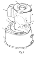
- the figures 1 and 2 illustrate a food preparation apparatus comprising a housing 1 having an upper face having a receiving base 2 having an eccentric driver 3 having the shape of a toothed ring protruding from the rear of the housing 1 and a central trainer 4 having the shape of a shaft provided with ribs extending over a greater height in the center of the housing 1.
- the receiving base 2 comprises a first recess 21, hollow, having an oblong contour adapted to receive the lower end of a blender container 5 having a bottom 50 receiving a rotary tool 6 eccentric in the bottom 50 of the container, shown in FIG. dotted on the figure 1 , and whose lower end mates with the eccentric driver 3 of the housing 1.
- the rotary tool 6 comprises, in a manner known per se, a cylindrical central hub 60 supporting a lower blade 61 having two branches curved downwards and an upper blade 62 having two branches curved upwards, the lower blades 61 and upper 62 being arranged at 90 ° to one another.
- the bottom 50 of the container has an oblong shaped contour having two semi-circular ends interconnected by two parallel straight lines and the container 5 comprises a casing 54, extending above the bottom 50 of the container, having a cross section similar in shape to that of the bottom 50 of the container, the casing 54 having a shape slightly divergent from the bottom 50 to the top of the container 5.
- the container also comprises, in the extension of the casing 54, a skirt 55 s extending under the bottom 50 of the container and having an oblong shape complementary to the shape of the first cavity 21 of the base 2 of reception.
- the container 5 is preferably closed by a lid 7 having a central opening 70 which can be closed by a removable cap, not shown in the figures, this opening 70 allowing the introduction of food into the container during the operation of the apparatus .
- the receiving base 2 also comprises a second recess 22, in relief, having a substantially circular contour that can receive the lower end of a chopper-type container, not shown in the figures, enclosing a tool that mates with the Central coach 4.
- the housing 1 contains an electric motor 10 whose operation is controlled by a control button 11 disposed on the front face of the housing 1, this motor being disposed in the rear part of the housing 1 and having an output shaft 10A of which upper end is coupled directly to the eccentric trainer 3.
- the output shaft 10A of the motor 10 supports a pinion 12 disposed under the eccentric driver 3, this pinion 12 being disposed inside the housing 1 and having a diameter of the order of 15 mm.
- This pinion 12 is geared on a toothed wheel 40 with a diameter of the order of 100 mm which extends under the receiving base 2 and which is integral with the central trainer 4 so as to drive the latter with a speed reduced by more than six times in relation to the rotational speed of the motor 10.
- the lower end of the shaft 10A is connected to a cooling fan 13 and the lower shell of the housing 1 has slots for the circulation of air under the fan 13.
- the motor 10 is preferably a universal type motor with a power of between 500W and 700W.
- the bottom 50 of the container comprises a step comprising a lower portion 51 disposed at one longitudinal end of the bottom of the container and an elevated portion 52 disposed at the other longitudinal end of the bottom of the container, the lower part 51 receiving the rotary tool 6 and the raised portion 52 having an inclined surface of the order of 30 ° relative to the horizontal, in the direction of the rotary tool 6.
- the raised portion 52 of the bottom of the container extends above the central driver 4 of the housing 1 and is at a level higher than that of the lower blade 61 of the rotary tool so that the lower blade 61 of the rotary tool is found bathed in a cavity gradually receiving all of the food flowing over the raised portion 52.
- the cavity thus formed has a depth of about 3 cm and comprises over the entire periphery of the tool, a wall at least 1 cm away from the path traveled by the end of the lower blade 61 of the rotary tool.
- the envelope 54 of the container has a smooth internal surface, that is to say without rib, and the lower part 51 of the bottom of the container has a substantially flat surface, extending around the tool rotary 6, which is connected to the raised portion 52 by a curved surface 53 having a point of inflection A at the height of the upper end of the hub 60 of the rotary tool.
- the curved surface 53 has a first portion, joining the point of inflection A and the lower part 51, having a radius of curvature of the order of 2 cm and a second part, establishing the junction between the point of inflection A and the raised portion 52, having a radius of curvature of the order of 3 cm, the slope of the curved surface 53 at the point of inflection A being of the order of 85 ° compared to the horizontal.
- Such a container has the advantage of making it possible to obtain a mixing flow generating a vortex according to the spiral arrows illustrated in FIG. figure 2 , generating excellent mixing of food throughout the container, while charging little rotational tool allowing to use a low power engine.
- Such a container also makes it possible to treat small amounts of ingredients with a very high efficiency, the presence of walking preventing the centrifugation of food outside the cavity.
- the container envelope being devoid of internal rib, it has the advantage of very easy cleaning.
- the step in the bottom of the container ensures a deviation of the vortex from the eccentric rotary tool to the center of the container so that the vortex sweeps the central part of the lid at the top of the container, thus avoiding the rise of liquid by the central opening of the cover during operation of the device.
- the shape of the cross section of the container may be different.
Landscapes
- Engineering & Computer Science (AREA)
- Food Science & Technology (AREA)
- Mechanical Engineering (AREA)
- Food-Manufacturing Devices (AREA)
Description
La présente invention se rapporte au domaine technique général des appareils électroménagers de préparation culinaire comportant un boîtier moteur et un récipient de travail comprenant un outil rotatif destiné à être entraîné en rotation par le boîtier moteur et se rapporte plus particulièrement à un récipient de travail de forme particulière.The present invention relates to the general technical field of electrical household appliances for culinary preparation comprising a motor housing and a working container comprising a rotary tool intended to be rotated by the motor housing and relates more particularly to a working container of form special.
Il est connu, du brevet
Cependant, un tel récipient comporte une enveloppe présentant une excroissance latérale en porte à faux par rapport au fond du récipient, ce qui présente l'inconvénient de rendre le récipient relativement instable lorsqu'il est posé sur une table. De plus, un tel récipient génère un flux dans lequel les aliments remontent le long des parois pour retomber violement au dessus de l'outil qui présente l'inconvénient de provoquer une charge importante sur l'outil rotatif, notamment lorsque le récipient contient beaucoup d'aliments. A l'inverse, un tel récipient présente une zone autour de l'outil où la paroi du récipient est relativement éloignée de l'outil, ce qui ne permet pas de mixer efficacement de faibles quantités d'aliments, ces derniers étant expulsés rapidement en dehors de la zone de travail de l'outil.However, such a container has an envelope having a lateral protrusion cantilevered from the bottom of the container, which has the disadvantage of making the container relatively unstable when placed on a table. In addition, such a container generates a flow in which food goes up along the walls to fall violently above the tool which has the disadvantage of causing a significant load on the rotary tool, especially when the container contains a lot of 'food. Conversely, such a container has an area around the tool where the wall of the container is relatively far from the tool, which does not effectively mix small amounts of food, the latter being expelled quickly in outside the working area of the tool.
Enfin, un tel récipient muni de nombreuses nervures présente l'inconvénient d'être difficile à nettoyer, la base des nervures formant des recoins dans lesquels les aliments ont tendance à s'agglomérer.Finally, such a container with many ribs has the disadvantage of being difficult to clean, the base of the ribs forming recesses in which food tends to agglomerate.
Il est également connu, de la demande de brevet
Cependant, un tel récipient ne permet pas un bon brassage des aliments lorsque peu d'aliments sont introduits dans le récipient.However, such a container does not allow a good mixing of food when little food is introduced into the container.
Aussi, un but de la présente invention est de proposer un récipient de travail pour appareil électroménager de préparation culinaire qui permette de traiter facilement de faibles quantités d'aliments et qui assure un flux de mixage progressif ne réclamant pas beaucoup de puissance au niveau de l'outil. Un autre but de la présente invention est de proposer un récipient de travail qui soit stable et facile à nettoyer.Also, an object of the present invention is to provide a working container for a food preparation appliance which makes it possible to easily handle small quantities of food and which ensures a progressive mixing flow that does not require much power at the level of the food processor. 'tool. Another object of the present invention is to provide a working container which is stable and easy to clean.
A cet effet, l'invention se rapporte à un récipient de travail, destiné à équiper un appareil électroménager de préparation culinaire de type blender, comprenant une enveloppe définissant un volume de traitement des aliments au dessus d'un fond comportant un outil rotatif destiné à être entraîné en rotation par un moteur, et comportant, dans le prolongement de l'enveloppe, une jupe s'étendant sous le fond du récipient, l'outil rotatif comportant au moins une lame inférieure s'étendant à proximité du fond du récipient, caractérisé en ce que le fond du récipient comporte une partie basse recevant l'outil rotatif et une partie surélevée formant une marche dans le fond du récipient, la partie surélevée présentant une surface inclinée en direction de la partie basse et s'étendant à un niveau supérieur à celui de la lame inférieure de l'outil rotatif.To this end, the invention relates to a working container, intended to equip a kitchen appliance blender type of food preparation, comprising an envelope defining a food processing volume above a bottom comprising a rotary tool for being rotated by a motor, and having, in the extension of the casing, a skirt extending under the bottom of the container, the rotary tool comprising at least one lower blade extending near the bottom of the container, characterized in that the bottom of the container comprises a bottom portion receiving the rotary tool and a raised portion forming a step in the bottom of the container, the raised portion having a surface inclined towards the bottom and extending at a level greater than that of the lower blade of the rotary tool.
Selon une autre caractéristique de l'invention, l'outil rotatif est excentré dans le fond du récipient.According to another characteristic of the invention, the rotary tool is eccentric in the bottom of the container.
Selon une autre caractéristique de l'invention, l'enveloppe du récipient est démunie de nervure.According to another characteristic of the invention, the envelope of the container has no rib.
Selon une autre caractéristique de l'invention, la partie basse et la partie surélevée du fond du récipient sont reliées entre elles par une surface courbe présentant un point d'inflexion.According to another characteristic of the invention, the lower part and the raised part of the bottom of the container are interconnected by a curved surface having a point of inflection.
Selon encore une autre caractéristique de l'invention, la pente de la surface courbe au niveau du point d'inflexion forme un angle de plus de 45° par rapport à l'horizontal.According to yet another characteristic of the invention, the slope of the curved surface at the point of inflection forms an angle of more than 45 ° with respect to the horizontal.
Selon encore une autre caractéristique de l'invention, le fond du récipient présente un contour oblong, la partie basse étant disposée à une extrémité longitudinale du fond du récipient et la partie surélevée étant disposée à l'autre extrémité longitudinale du fond du récipient.According to yet another characteristic of the invention, the bottom of the container has an oblong contour, the lower part being disposed at one longitudinal end of the bottom of the container and the raised portion being disposed at the other longitudinal end of the bottom of the container.
Selon une autre caractéristique de l'invention, le fond du récipient présente un contour constitué par deux extrémités semi-circulaires reliées entre elles par deux droites parallèles.According to another characteristic of the invention, the bottom of the container has a contour consisting of two semi-circular ends interconnected by two parallel lines.
Selon une autre caractéristique de l'invention, l'enveloppe du récipient présente une section transversale de forme semblable à celle du fond du récipient, l'enveloppe étant faiblement divergente du fond vers le sommet du récipient.According to another characteristic of the invention, the envelope of the container has a cross section similar in shape to that of the bottom of the container, the envelope being slightly divergent from the bottom to the top of the container.
Selon une autre caractéristique de l'invention, le récipient comporte un couvercle comprenant une ouverture centrale pour l'introduction des aliments.According to another characteristic of the invention, the container comprises a lid comprising a central opening for the introduction of food.
Selon une autre caractéristique de l'invention, le fond et l'enveloppe du récipient définissent une cavité comportant, sur toute la périphérie de l'outil rotatif, une paroi distante de moins de 1 cm de la trajectoire parcourue par l'extrémité de la lame inférieure de l'outil rotatif.According to another characteristic of the invention, the bottom and the shell of the container define a cavity comprising, over the entire periphery of the rotary tool, a wall at least 1 cm away from the path traversed by the end of the lower blade of the rotary tool.
L'invention concerne également un appareil électroménager de préparation culinaire comportant un boîtier renfermant un moteur et comportant un récipient de travail comprenant un outil rotatif entraîné en rotation par le moteur, caractérisé en ce que le récipient est conforme au récipient selon l'invention précédemment décrit.The invention also relates to an electrical household appliance for culinary preparation comprising a housing enclosing a motor and comprising a working receptacle comprising a rotary tool driven in rotation by the motor, characterized in that the receptacle conforms to the receptacle according to the invention described above. .
On comprendra mieux les buts, aspects et avantages de la présente invention, d'après la description donnée ci-après d'un mode particulier de réalisation de l'invention présenté à titre d'exemple non limitatif, en se référant aux dessins annexés dans lesquels :
- la
figure 1 est une vue en perspective d'un appareil blender selon un mode particulier de réalisation de l'invention, - la
figure 2 est une vue en coupe longitudinale de l'appareil de lafigure 1 .
- the
figure 1 is a perspective view of a blender apparatus according to a particular embodiment of the invention, - the
figure 2 is a longitudinal sectional view of the apparatus of thefigure 1 .
Seuls les éléments nécessaires à la compréhension de l'invention ont été représentés. Pour faciliter la lecture des dessins les mêmes éléments portent les mêmes références d'une figure à l'autre.Only the elements necessary for the understanding of the invention have been represented. To facilitate the reading of the drawings, the same elements bear the same references from one figure to another.
Les
Le socle de réception 2 comporte une première empreinte 21, en creux, présentant un contour oblong adapté pour recevoir l'extrémité inférieure d'un récipient blender 5 comportant un fond 50 recevant un outil rotatif 6 excentré dans le fond 50 du récipient, représentés en pointillé sur la
L'outil rotatif 6 comporte, de manière connue en soi, un moyeu central 60 cylindrique supportant une lame inférieure 61 présentant deux branches incurvées vers le bas et une lame supérieure 62 présentant deux branches incurvées vers le haut, les lames inférieure 61 et supérieure 62 étant disposées à 90° l'une de l'autre.The
De manière avantageuse, le fond 50 du récipient comporte un contour de forme oblongue présentant deux extrémités semi-circulaires reliées entre elles par deux droites parallèles et le récipient 5 comporte une enveloppe 54, s'étendant au dessus du fond 50 du récipient, présentant une section transversale de forme similaire à celle du fond 50 du récipient, l'enveloppe 54 présentant une forme légèrement divergente du fond 50 vers le sommet du récipient 5. Le récipient comporte également, dans le prolongement de l'enveloppe 54, une jupe 55 s'étendant sous le fond 50 du récipient et présentant une forme oblongue complémentaire à la forme de la première empreinte 21 du socle 2 de réception.Advantageously, the
Le récipient 5 est préférentiellement fermé par un couvercle 7 comportant une ouverture centrale 70 pouvant être fermée par un capuchon amovible, non représenté sur les figures, cette ouverture 70 permettant l'introduction d'aliments dans le récipient au cours du fonctionnement de l'appareil.The container 5 is preferably closed by a
Le socle de réception 2 comporte également une seconde empreinte 22, en relief, présentant un contour sensiblement circulaire pouvant recevoir l'extrémité inférieure d'un récipient de type hachoir, non représenté sur les figures, renfermant un outil venant s'accoupler avec l'entraîneur 4 central.The
Conformément à la
L'arbre de sortie 10A du moteur 10 supporte un pignon 12 disposé sous l'entraîneur 3 excentré, ce pignon 12 étant disposé à l'intérieur du boîtier 1 et présentant un diamètre de l'ordre de 15 mm. Ce pignon 12 est engrené sur une roue dentée 40 d'un diamètre de l'ordre de 100 mm qui s'étend sous le socle de réception 2 et qui est solidaire de l'entraîneur central 4 de manière à entraîner ce dernier avec une vitesse réduite de plus de six fois par rapport à la vitesse de rotation du moteur 10.The
Afin de favoriser le refroidissement du moteur, l'extrémité inférieure de l'arbre 10A est reliée à un ventilateur de refroidissement 13 et la coque inférieure du boîtier 1 comporte des fentes pour la circulation de l'air sous ce ventilateur 13.To promote engine cooling, the lower end of the
Le moteur 10 est préférentiellement un moteur de type universel d'une puissance comprise entre 500W et 700W.The
Plus particulièrement selon l'invention, le fond 50 du récipient comporte une marche comprenant une partie basse 51 disposée à une extrémité longitudinale du fond du récipient et une partie surélevée 52 disposée à l'autre extrémité longitudinale du fond du récipient, la partie basse 51 recevant l'outil rotatif 6 et la partie surélevée 52 présentant une surface inclinée de l'ordre de 30° par rapport à l'horizontal, en direction de l'outil rotatif 6.More particularly according to the invention, the
La partie surélevée 52 du fond du récipient s'étend au dessus de l'entraîneur 4 central du boîtier 1 et se trouve à un niveau supérieur à celui de la lame inférieure 61 de l'outil rotatif de sorte que la lame inférieure 61 de l'outil rotatif se retrouve baignée dans une cavité recevant progressivement l'ensemble des aliments s'écoulant sur la partie surélevée 52. De manière préférentielle, la cavité ainsi formée présente une profondeur de l'ordre de 3 cm et comporte sur toute la périphérie de l'outil, une paroi distante de moins de 1 cm de la trajectoire parcourue par l'extrémité de la lame inférieure 61 de l'outil rotatif.The raised
De manière avantageuse, l'enveloppe 54 du récipient comporte une surface interne lisse, c'est-à-dire démunie de nervure, et la partie basse 51 du fond du récipient présente une surface sensiblement plane, s'étendant autour de l'outil rotatif 6, qui est reliée à la partie surélevée 52 par une surface courbe 53 comportant un point d'inflexion A à hauteur de l'extrémité supérieure du moyeu 60 de l'outil rotatif.Advantageously, the
A titre d'exemple, la surface courbe 53 présente une première partie, faisant la jonction entre le point d'inflexion A et la partie basse 51, présentant un rayon de courbure de l'ordre de 2 cm et une deuxième partie, établissant la jonction entre le point d'inflexion A et la partie surélevée 52, présentant un rayon de courbure de l'ordre de 3 cm, la pente de la surface courbe 53 au niveau du point d'inflexion A étant de l'ordre de 85° par rapport à l'horizontal.For example, the
Un tel récipient présente l'avantage de permettre l'obtention d'un flux de mixage générant un vortex suivant les flèches en spirale illustrées sur la
De plus, l'enveloppe du récipient étant démunie de nervure interne, elle présente l'avantage d'une très grande facilité de nettoyage.In addition, the container envelope being devoid of internal rib, it has the advantage of very easy cleaning.
Enfin, la marche dans le fond du récipient assure une déviation du vortex depuis l'outil rotatif excentré vers le centre du récipient de sorte que le vortex balaye la partie centrale du couvercle en haut du récipient, évitant ainsi la remonté de liquide par l'ouverture centrale du couvercle lors du fonctionnement de l'appareil.Finally, the step in the bottom of the container ensures a deviation of the vortex from the eccentric rotary tool to the center of the container so that the vortex sweeps the central part of the lid at the top of the container, thus avoiding the rise of liquid by the central opening of the cover during operation of the device.
Bien entendu, l'invention n'est nullement limitée au mode de réalisation décrit et illustré qui n'a été donné qu'à titre d'exemple. Des modifications restent possibles, notamment du point de vue de la constitution des divers éléments ou par substitution d'équivalents techniques, sans sortir pour autant du domaine de protection de l'invention.Of course, the invention is not limited to the embodiment described and illustrated which has been given by way of example. Modifications are possible, particularly from the point of view of the constitution of the various elements or by substitution of technical equivalents, without departing from the scope of protection of the invention.
Ainsi, dans une variante de réalisation de l'invention, la forme de la section transversale du récipient pourra être différente.Thus, in an alternative embodiment of the invention, the shape of the cross section of the container may be different.
Claims (9)
- A working container (5), for an electrical household food preparation appliance such as a blender, comprising a casing (54) defining a volume wherein food is processed above a bottom (50) comprising a rotary tool (6) to be driven in rotation by a motor (10) and comprising, in the extension of the casing (54), a skirt (55) extending below the bottom (50) of the container, said rotary tool (6) comprising at least one lower blade (61) extending close to the bottom (50) of the container, the bottom (50) of the container having a lower portion (51) receiving the rotary tool (6) and a raised portion (52) forming a step in the bottom (50) of the container, the raised portion (52) having a surface inclined towards the lower portion (51) and extending to a level higher than that of the lower blade (61) of the rotary tool (6), characterised in that the rotary tool (6) is arranged eccentrically in the bottom (50) of the container (5) and in that the lower portion (51) and the raised portion (52) of the container bottom are connected with each other by a curved surface (53) having a point of inflection (A).
- A container according to claim 1, characterised in that the casing (54) of the container is devoid of rib.
- A container according to any one of claims 1 to 2, characterised in that the slope of the curved surface (53) at the point of inflection (A) forms an angle of more than 45° relative to the horizontal.
- A container according to any one of claims 1 to 3, characterised in that the bottom (50) of the container has an oblong contour and in that the lower portion (51) is arranged at one longitudinal end of the bottom (50) of the container and the raised portion (52) being arranged at the other longitudinal end of the bottom (50) of the container (5).
- A container according to claim 4, characterised that the bottom (50) of the container has a contour consisting of two semi-circular ends joined together by two parallel lines.
- A container according to any one of claims 1 to 5, characterised in that the casing (54) of the container has a cross-section with a shape similar to that of the bottom (50) of the container, the casing (54) being slightly divergent from the bottom to the top of the container (5).
- A container according to any one of claims 1 to 6, characterised in that the container (5) has a cover (7) comprising a central opening (70) for the introduction of food.
- A container according to any one of claims 1 to 7, characterised in that the bottom (50) and the casing (54) of the container define a cavity having, on the entire periphery of the rotary tool (6), a wall at least 1 cm away from the trajectory taken by the end of the lower blade (61) of the rotary tool.
- An electrical household food preparation appliance comprising a housing (1) containing a motor (10) and comprising a working container (5) comprising a rotary tool (6) driven in rotation by said motor (10), characterised in that said container conforms to one of claims 1 to 8.
Applications Claiming Priority (1)
| Application Number | Priority Date | Filing Date | Title |
|---|---|---|---|
| FR0708863A FR2925278B1 (en) | 2007-12-19 | 2007-12-19 | WORKING CONTAINER FOR CULINARY PREPARATION ELECTRICAL APPLIANCE APPARATUS AND APPARATUS PROVIDED WITH SUCH A CONTAINER |
Publications (2)
| Publication Number | Publication Date |
|---|---|
| EP2071989A1 EP2071989A1 (en) | 2009-06-24 |
| EP2071989B1 true EP2071989B1 (en) | 2013-07-24 |
Family
ID=39787864
Family Applications (1)
| Application Number | Title | Priority Date | Filing Date |
|---|---|---|---|
| EP20080356154 Active EP2071989B1 (en) | 2007-12-19 | 2008-12-16 | Work container for a household cooking appliance and appliance equipped with such a container |
Country Status (4)
| Country | Link |
|---|---|
| EP (1) | EP2071989B1 (en) |
| CN (1) | CN101461673B (en) |
| FR (1) | FR2925278B1 (en) |
| WO (1) | WO2009106709A2 (en) |
Families Citing this family (13)
| Publication number | Priority date | Publication date | Assignee | Title |
|---|---|---|---|---|
| EP2229853A1 (en) * | 2009-03-19 | 2010-09-22 | Green Lane Products Ltd. | Milk frothing device |
| GB201004136D0 (en) * | 2010-03-12 | 2010-04-28 | Green Lane Products Ltd | Milk frothing device |
| GB201004135D0 (en) * | 2010-03-12 | 2010-04-28 | Green Lane Products Ltd | Electrical apparatus |
| US8720325B2 (en) | 2010-04-29 | 2014-05-13 | Whirlpool Corporation | Food processor with a lockable adjustable blade assembly |
| US10449685B2 (en) | 2010-04-29 | 2019-10-22 | Whirlpool Corporation | Food processor with adjustable blade assembly |
| US8800905B2 (en) | 2011-02-08 | 2014-08-12 | Main Power Electrical Factory Ltd. | Mixing vessel |
| US10085599B2 (en) | 2014-12-19 | 2018-10-02 | Whirlpool Corporation | Multi-cook and food processing prep product |
| CA3035998C (en) * | 2016-10-28 | 2022-09-27 | Guangdong Midea Consumer Electrics Manufacturing Co., Ltd. | Food processor |
| CN107296533B (en) * | 2016-10-28 | 2023-05-26 | 广东美的生活电器制造有限公司 | Food processor |
| USD853782S1 (en) | 2017-02-20 | 2019-07-16 | Whirlpool Corporation | Food processor |
| US10575683B2 (en) | 2017-03-15 | 2020-03-03 | Spectrum Brands, Inc. | Quiet appliance motor housing |
| CN112781676B (en) * | 2019-11-08 | 2023-03-17 | 九阳股份有限公司 | Capacity detection method based on motor attribute and food processing machine |
| MX2023013337A (en) | 2021-05-11 | 2023-11-27 | Seb Sa | Large-capacity mixing and blending container, and appliance for food preparation comprising such a container. |
Family Cites Families (4)
| Publication number | Priority date | Publication date | Assignee | Title |
|---|---|---|---|---|
| DE3933036C3 (en) * | 1989-10-04 | 1996-02-08 | Braun Ag | Motorized multi-purpose food processor |
| US5323973A (en) * | 1993-04-20 | 1994-06-28 | Ferrara Jr Daniel A | Kitchen blender |
| CN1261067C (en) * | 2003-05-10 | 2006-06-28 | 黄顺贤 | Multifunctional juice squeezing and stirring machine for fruit and vegetable |
| US7918601B2 (en) * | 2005-02-04 | 2011-04-05 | Hamilton Beach Brands, Inc. | Dispensing blender jar |
-
2007
- 2007-12-19 FR FR0708863A patent/FR2925278B1/en active Active
-
2008
- 2008-12-15 CN CN2008101831806A patent/CN101461673B/en active Active
- 2008-12-16 EP EP20080356154 patent/EP2071989B1/en active Active
- 2008-12-16 WO PCT/FR2008/001749 patent/WO2009106709A2/en active Application Filing
Also Published As
| Publication number | Publication date |
|---|---|
| FR2925278B1 (en) | 2012-08-31 |
| WO2009106709A2 (en) | 2009-09-03 |
| EP2071989A1 (en) | 2009-06-24 |
| WO2009106709A3 (en) | 2009-10-29 |
| CN101461673A (en) | 2009-06-24 |
| CN101461673B (en) | 2011-12-07 |
| FR2925278A1 (en) | 2009-06-26 |
Similar Documents
| Publication | Publication Date | Title |
|---|---|---|
| EP2071989B1 (en) | Work container for a household cooking appliance and appliance equipped with such a container | |
| EP2085005B1 (en) | Household cooking appliance with a housing containing a motor and a container with a rotary tool | |
| EP1772087B1 (en) | Mixing rod and domestic mixing device of the immersing type with such a mixing rod | |
| EP2227125B1 (en) | Electrical household appliance comprising a working container fitted with a filter | |
| EP1900315B1 (en) | Immersed domestic mixer comprising a work tool in the shape of an Archimedes screw | |
| EP2206455A1 (en) | Household cooking appliance including a first and second working container on a case | |
| EP2675331B1 (en) | Electric household appliance for preparing food, comprising a means for driving a working tool in a planetary motion | |
| EP2074919B1 (en) | Electrical kitchen appliance comprising a casing with several driving means located on a supporting base | |
| EP1858633B1 (en) | Blender-type electrical cooking appliance comprising a stirrer | |
| EP2892405B1 (en) | Household food preparation apparatus comprising a dough-mixing hook driven in a planetary motion | |
| WO2000036960A1 (en) | Multifunction food processor | |
| EP3311719B1 (en) | Electrical kitchen appliance having a discharge duct | |
| FR2569970A1 (en) | Multipurpose kitchen appliance | |
| FR3057753B1 (en) | CULINARY PREPARATION ELECTRICAL APPLIANCE COMPRISING AN ELECTRIC POWER SUPPLY BASE | |
| FR3051651A1 (en) | PETROLING TOOL FOR CULINARY PREPARATION ELECTRICAL APPLIANCES | |
| EP2429359B1 (en) | Household culinary appliance comprising a working container in thermal contact with a heating element | |
| FR2877557A1 (en) | Working container closing cover for electric household appliance e.g. food processor, has speed accelerator/reducer module including input and output shafts and disposed in detachable module that is disposed in central cavity in cover body | |
| EP2124689A1 (en) | Filter for the production of crushed ice using a hand-held blender and device for producing crushed ice fitted with such filter | |
| EP3079542A1 (en) | Household food preparation appliance comprising a lower arm borne by a base and an upper arm connected to the lower arm by a hinge means | |
| BE525659A (en) |
Legal Events
| Date | Code | Title | Description |
|---|---|---|---|
| PUAI | Public reference made under article 153(3) epc to a published international application that has entered the european phase |
Free format text: ORIGINAL CODE: 0009012 |
|
| AK | Designated contracting states |
Kind code of ref document: A1 Designated state(s): AT BE BG CH CY CZ DE DK EE ES FI FR GB GR HR HU IE IS IT LI LT LU LV MC MT NL NO PL PT RO SE SI SK TR |
|
| AX | Request for extension of the european patent |
Extension state: AL BA MK RS |
|
| 17P | Request for examination filed |
Effective date: 20091221 |
|
| AKX | Designation fees paid |
Designated state(s): AT BE BG CH CY CZ DE DK EE ES FI FR GB GR HR HU IE IS IT LI LT LU LV MC MT NL NO PL PT RO SE SI SK TR |
|
| 17Q | First examination report despatched |
Effective date: 20100204 |
|
| GRAP | Despatch of communication of intention to grant a patent |
Free format text: ORIGINAL CODE: EPIDOSNIGR1 |
|
| INTG | Intention to grant announced |
Effective date: 20130508 |
|
| GRAS | Grant fee paid |
Free format text: ORIGINAL CODE: EPIDOSNIGR3 |
|
| GRAA | (expected) grant |
Free format text: ORIGINAL CODE: 0009210 |
|
| AK | Designated contracting states |
Kind code of ref document: B1 Designated state(s): AT BE BG CH CY CZ DE DK EE ES FI FR GB GR HR HU IE IS IT LI LT LU LV MC MT NL NO PL PT RO SE SI SK TR |
|
| REG | Reference to a national code |
Ref country code: GB Ref legal event code: FG4D Free format text: NOT ENGLISH |
|
| REG | Reference to a national code |
Ref country code: CH Ref legal event code: EP |
|
| REG | Reference to a national code |
Ref country code: AT Ref legal event code: REF Ref document number: 622900 Country of ref document: AT Kind code of ref document: T Effective date: 20130815 |
|
| REG | Reference to a national code |
Ref country code: IE Ref legal event code: FG4D Free format text: LANGUAGE OF EP DOCUMENT: FRENCH |
|
| REG | Reference to a national code |
Ref country code: DE Ref legal event code: R096 Ref document number: 602008026224 Country of ref document: DE Effective date: 20130919 |
|
| REG | Reference to a national code |
Ref country code: AT Ref legal event code: MK05 Ref document number: 622900 Country of ref document: AT Kind code of ref document: T Effective date: 20130724 |
|
| REG | Reference to a national code |
Ref country code: NL Ref legal event code: VDEP Effective date: 20130724 |
|
| REG | Reference to a national code |
Ref country code: LT Ref legal event code: MG4D |
|
| PG25 | Lapsed in a contracting state [announced via postgrant information from national office to epo] |
Ref country code: LT Free format text: LAPSE BECAUSE OF FAILURE TO SUBMIT A TRANSLATION OF THE DESCRIPTION OR TO PAY THE FEE WITHIN THE PRESCRIBED TIME-LIMIT Effective date: 20130724 Ref country code: PT Free format text: LAPSE BECAUSE OF FAILURE TO SUBMIT A TRANSLATION OF THE DESCRIPTION OR TO PAY THE FEE WITHIN THE PRESCRIBED TIME-LIMIT Effective date: 20131125 Ref country code: NO Free format text: LAPSE BECAUSE OF FAILURE TO SUBMIT A TRANSLATION OF THE DESCRIPTION OR TO PAY THE FEE WITHIN THE PRESCRIBED TIME-LIMIT Effective date: 20131024 Ref country code: IS Free format text: LAPSE BECAUSE OF FAILURE TO SUBMIT A TRANSLATION OF THE DESCRIPTION OR TO PAY THE FEE WITHIN THE PRESCRIBED TIME-LIMIT Effective date: 20131124 Ref country code: SE Free format text: LAPSE BECAUSE OF FAILURE TO SUBMIT A TRANSLATION OF THE DESCRIPTION OR TO PAY THE FEE WITHIN THE PRESCRIBED TIME-LIMIT Effective date: 20130724 Ref country code: CY Free format text: LAPSE BECAUSE OF FAILURE TO SUBMIT A TRANSLATION OF THE DESCRIPTION OR TO PAY THE FEE WITHIN THE PRESCRIBED TIME-LIMIT Effective date: 20130731 Ref country code: AT Free format text: LAPSE BECAUSE OF FAILURE TO SUBMIT A TRANSLATION OF THE DESCRIPTION OR TO PAY THE FEE WITHIN THE PRESCRIBED TIME-LIMIT Effective date: 20130724 Ref country code: HR Free format text: LAPSE BECAUSE OF FAILURE TO SUBMIT A TRANSLATION OF THE DESCRIPTION OR TO PAY THE FEE WITHIN THE PRESCRIBED TIME-LIMIT Effective date: 20130724 |
|
| PG25 | Lapsed in a contracting state [announced via postgrant information from national office to epo] |
Ref country code: LV Free format text: LAPSE BECAUSE OF FAILURE TO SUBMIT A TRANSLATION OF THE DESCRIPTION OR TO PAY THE FEE WITHIN THE PRESCRIBED TIME-LIMIT Effective date: 20130724 Ref country code: PL Free format text: LAPSE BECAUSE OF FAILURE TO SUBMIT A TRANSLATION OF THE DESCRIPTION OR TO PAY THE FEE WITHIN THE PRESCRIBED TIME-LIMIT Effective date: 20130724 Ref country code: ES Free format text: LAPSE BECAUSE OF FAILURE TO SUBMIT A TRANSLATION OF THE DESCRIPTION OR TO PAY THE FEE WITHIN THE PRESCRIBED TIME-LIMIT Effective date: 20130724 Ref country code: SI Free format text: LAPSE BECAUSE OF FAILURE TO SUBMIT A TRANSLATION OF THE DESCRIPTION OR TO PAY THE FEE WITHIN THE PRESCRIBED TIME-LIMIT Effective date: 20130724 Ref country code: FI Free format text: LAPSE BECAUSE OF FAILURE TO SUBMIT A TRANSLATION OF THE DESCRIPTION OR TO PAY THE FEE WITHIN THE PRESCRIBED TIME-LIMIT Effective date: 20130724 Ref country code: GR Free format text: LAPSE BECAUSE OF FAILURE TO SUBMIT A TRANSLATION OF THE DESCRIPTION OR TO PAY THE FEE WITHIN THE PRESCRIBED TIME-LIMIT Effective date: 20131025 Ref country code: NL Free format text: LAPSE BECAUSE OF FAILURE TO SUBMIT A TRANSLATION OF THE DESCRIPTION OR TO PAY THE FEE WITHIN THE PRESCRIBED TIME-LIMIT Effective date: 20130724 |
|
| PG25 | Lapsed in a contracting state [announced via postgrant information from national office to epo] |
Ref country code: CY Free format text: LAPSE BECAUSE OF FAILURE TO SUBMIT A TRANSLATION OF THE DESCRIPTION OR TO PAY THE FEE WITHIN THE PRESCRIBED TIME-LIMIT Effective date: 20130724 |
|
| PG25 | Lapsed in a contracting state [announced via postgrant information from national office to epo] |
Ref country code: EE Free format text: LAPSE BECAUSE OF FAILURE TO SUBMIT A TRANSLATION OF THE DESCRIPTION OR TO PAY THE FEE WITHIN THE PRESCRIBED TIME-LIMIT Effective date: 20130724 Ref country code: RO Free format text: LAPSE BECAUSE OF FAILURE TO SUBMIT A TRANSLATION OF THE DESCRIPTION OR TO PAY THE FEE WITHIN THE PRESCRIBED TIME-LIMIT Effective date: 20130724 Ref country code: CZ Free format text: LAPSE BECAUSE OF FAILURE TO SUBMIT A TRANSLATION OF THE DESCRIPTION OR TO PAY THE FEE WITHIN THE PRESCRIBED TIME-LIMIT Effective date: 20130724 Ref country code: DK Free format text: LAPSE BECAUSE OF FAILURE TO SUBMIT A TRANSLATION OF THE DESCRIPTION OR TO PAY THE FEE WITHIN THE PRESCRIBED TIME-LIMIT Effective date: 20130724 Ref country code: SK Free format text: LAPSE BECAUSE OF FAILURE TO SUBMIT A TRANSLATION OF THE DESCRIPTION OR TO PAY THE FEE WITHIN THE PRESCRIBED TIME-LIMIT Effective date: 20130724 |
|
| PG25 | Lapsed in a contracting state [announced via postgrant information from national office to epo] |
Ref country code: IT Free format text: LAPSE BECAUSE OF FAILURE TO SUBMIT A TRANSLATION OF THE DESCRIPTION OR TO PAY THE FEE WITHIN THE PRESCRIBED TIME-LIMIT Effective date: 20130724 |
|
| PLBE | No opposition filed within time limit |
Free format text: ORIGINAL CODE: 0009261 |
|
| STAA | Information on the status of an ep patent application or granted ep patent |
Free format text: STATUS: NO OPPOSITION FILED WITHIN TIME LIMIT |
|
| 26N | No opposition filed |
Effective date: 20140425 |
|
| REG | Reference to a national code |
Ref country code: CH Ref legal event code: PL |
|
| REG | Reference to a national code |
Ref country code: DE Ref legal event code: R097 Ref document number: 602008026224 Country of ref document: DE Effective date: 20140425 |
|
| PG25 | Lapsed in a contracting state [announced via postgrant information from national office to epo] |
Ref country code: LU Free format text: LAPSE BECAUSE OF FAILURE TO SUBMIT A TRANSLATION OF THE DESCRIPTION OR TO PAY THE FEE WITHIN THE PRESCRIBED TIME-LIMIT Effective date: 20131216 Ref country code: MC Free format text: LAPSE BECAUSE OF FAILURE TO SUBMIT A TRANSLATION OF THE DESCRIPTION OR TO PAY THE FEE WITHIN THE PRESCRIBED TIME-LIMIT Effective date: 20130724 |
|
| REG | Reference to a national code |
Ref country code: IE Ref legal event code: MM4A |
|
| PG25 | Lapsed in a contracting state [announced via postgrant information from national office to epo] |
Ref country code: LI Free format text: LAPSE BECAUSE OF NON-PAYMENT OF DUE FEES Effective date: 20131231 Ref country code: CH Free format text: LAPSE BECAUSE OF NON-PAYMENT OF DUE FEES Effective date: 20131231 Ref country code: IE Free format text: LAPSE BECAUSE OF NON-PAYMENT OF DUE FEES Effective date: 20131216 |
|
| PG25 | Lapsed in a contracting state [announced via postgrant information from national office to epo] |
Ref country code: TR Free format text: LAPSE BECAUSE OF FAILURE TO SUBMIT A TRANSLATION OF THE DESCRIPTION OR TO PAY THE FEE WITHIN THE PRESCRIBED TIME-LIMIT Effective date: 20130724 |
|
| PG25 | Lapsed in a contracting state [announced via postgrant information from national office to epo] |
Ref country code: HU Free format text: LAPSE BECAUSE OF FAILURE TO SUBMIT A TRANSLATION OF THE DESCRIPTION OR TO PAY THE FEE WITHIN THE PRESCRIBED TIME-LIMIT; INVALID AB INITIO Effective date: 20081216 Ref country code: BG Free format text: LAPSE BECAUSE OF FAILURE TO SUBMIT A TRANSLATION OF THE DESCRIPTION OR TO PAY THE FEE WITHIN THE PRESCRIBED TIME-LIMIT Effective date: 20130724 |
|
| PG25 | Lapsed in a contracting state [announced via postgrant information from national office to epo] |
Ref country code: MT Free format text: LAPSE BECAUSE OF FAILURE TO SUBMIT A TRANSLATION OF THE DESCRIPTION OR TO PAY THE FEE WITHIN THE PRESCRIBED TIME-LIMIT Effective date: 20130724 |
|
| REG | Reference to a national code |
Ref country code: FR Ref legal event code: PLFP Year of fee payment: 8 |
|
| REG | Reference to a national code |
Ref country code: FR Ref legal event code: PLFP Year of fee payment: 9 |
|
| REG | Reference to a national code |
Ref country code: FR Ref legal event code: CA Effective date: 20170518 |
|
| REG | Reference to a national code |
Ref country code: FR Ref legal event code: PLFP Year of fee payment: 10 |
|
| P01 | Opt-out of the competence of the unified patent court (upc) registered |
Effective date: 20230517 |
|
| PGFP | Annual fee paid to national office [announced via postgrant information from national office to epo] |
Ref country code: GB Payment date: 20231220 Year of fee payment: 16 |
|
| PGFP | Annual fee paid to national office [announced via postgrant information from national office to epo] |
Ref country code: FR Payment date: 20231220 Year of fee payment: 16 Ref country code: DE Payment date: 20231208 Year of fee payment: 16 |
|
| PGFP | Annual fee paid to national office [announced via postgrant information from national office to epo] |
Ref country code: BE Payment date: 20231212 Year of fee payment: 16 |