EP2071691A2 - Compensateur d'energie reactive - Google Patents
Compensateur d'energie reactive Download PDFInfo
- Publication number
- EP2071691A2 EP2071691A2 EP07822880A EP07822880A EP2071691A2 EP 2071691 A2 EP2071691 A2 EP 2071691A2 EP 07822880 A EP07822880 A EP 07822880A EP 07822880 A EP07822880 A EP 07822880A EP 2071691 A2 EP2071691 A2 EP 2071691A2
- Authority
- EP
- European Patent Office
- Prior art keywords
- power
- reactive power
- control means
- reactive
- wind power
- Prior art date
- Legal status (The legal status is an assumption and is not a legal conclusion. Google has not performed a legal analysis and makes no representation as to the accuracy of the status listed.)
- Withdrawn
Links
- 239000003990 capacitor Substances 0.000 claims abstract description 22
- 230000006698 induction Effects 0.000 claims abstract description 16
- 230000001939 inductive effect Effects 0.000 claims abstract description 8
- 230000003068 static effect Effects 0.000 claims abstract description 6
- 238000004458 analytical method Methods 0.000 claims abstract description 3
- 238000001514 detection method Methods 0.000 claims abstract description 3
- 238000002347 injection Methods 0.000 claims description 13
- 239000007924 injection Substances 0.000 claims description 13
- 238000005259 measurement Methods 0.000 claims description 7
- 230000009466 transformation Effects 0.000 claims description 5
- 238000000034 method Methods 0.000 claims description 3
- 238000011084 recovery Methods 0.000 description 3
- 238000009434 installation Methods 0.000 description 2
- 230000000712 assembly Effects 0.000 description 1
- 238000000429 assembly Methods 0.000 description 1
- 238000010276 construction Methods 0.000 description 1
- 239000000843 powder Substances 0.000 description 1
- 238000010248 power generation Methods 0.000 description 1
Images

Classifications
-
- F—MECHANICAL ENGINEERING; LIGHTING; HEATING; WEAPONS; BLASTING
- F03—MACHINES OR ENGINES FOR LIQUIDS; WIND, SPRING, OR WEIGHT MOTORS; PRODUCING MECHANICAL POWER OR A REACTIVE PROPULSIVE THRUST, NOT OTHERWISE PROVIDED FOR
- F03D—WIND MOTORS
- F03D9/00—Adaptations of wind motors for special use; Combinations of wind motors with apparatus driven thereby; Wind motors specially adapted for installation in particular locations
- F03D9/20—Wind motors characterised by the driven apparatus
- F03D9/25—Wind motors characterised by the driven apparatus the apparatus being an electrical generator
- F03D9/255—Wind motors characterised by the driven apparatus the apparatus being an electrical generator connected to electrical distribution networks; Arrangements therefor
-
- H—ELECTRICITY
- H02—GENERATION; CONVERSION OR DISTRIBUTION OF ELECTRIC POWER
- H02J—CIRCUIT ARRANGEMENTS OR SYSTEMS FOR SUPPLYING OR DISTRIBUTING ELECTRIC POWER; SYSTEMS FOR STORING ELECTRIC ENERGY
- H02J3/00—Circuit arrangements for ac mains or ac distribution networks
- H02J3/18—Arrangements for adjusting, eliminating or compensating reactive power in networks
- H02J3/1821—Arrangements for adjusting, eliminating or compensating reactive power in networks using shunt compensators
- H02J3/1828—Arrangements for adjusting, eliminating or compensating reactive power in networks using shunt compensators with stepwise control, the possibility of switching in or out the entire compensating arrangement not being considered as stepwise control
-
- H—ELECTRICITY
- H02—GENERATION; CONVERSION OR DISTRIBUTION OF ELECTRIC POWER
- H02J—CIRCUIT ARRANGEMENTS OR SYSTEMS FOR SUPPLYING OR DISTRIBUTING ELECTRIC POWER; SYSTEMS FOR STORING ELECTRIC ENERGY
- H02J3/00—Circuit arrangements for ac mains or ac distribution networks
- H02J3/12—Circuit arrangements for ac mains or ac distribution networks for adjusting voltage in ac networks by changing a characteristic of the network load
- H02J3/16—Circuit arrangements for ac mains or ac distribution networks for adjusting voltage in ac networks by changing a characteristic of the network load by adjustment of reactive power
-
- H—ELECTRICITY
- H02—GENERATION; CONVERSION OR DISTRIBUTION OF ELECTRIC POWER
- H02J—CIRCUIT ARRANGEMENTS OR SYSTEMS FOR SUPPLYING OR DISTRIBUTING ELECTRIC POWER; SYSTEMS FOR STORING ELECTRIC ENERGY
- H02J3/00—Circuit arrangements for ac mains or ac distribution networks
- H02J3/18—Arrangements for adjusting, eliminating or compensating reactive power in networks
-
- H—ELECTRICITY
- H02—GENERATION; CONVERSION OR DISTRIBUTION OF ELECTRIC POWER
- H02J—CIRCUIT ARRANGEMENTS OR SYSTEMS FOR SUPPLYING OR DISTRIBUTING ELECTRIC POWER; SYSTEMS FOR STORING ELECTRIC ENERGY
- H02J3/00—Circuit arrangements for ac mains or ac distribution networks
- H02J3/38—Arrangements for parallely feeding a single network by two or more generators, converters or transformers
-
- H—ELECTRICITY
- H02—GENERATION; CONVERSION OR DISTRIBUTION OF ELECTRIC POWER
- H02J—CIRCUIT ARRANGEMENTS OR SYSTEMS FOR SUPPLYING OR DISTRIBUTING ELECTRIC POWER; SYSTEMS FOR STORING ELECTRIC ENERGY
- H02J2300/00—Systems for supplying or distributing electric power characterised by decentralized, dispersed, or local generation
- H02J2300/20—The dispersed energy generation being of renewable origin
- H02J2300/28—The renewable source being wind energy
-
- H—ELECTRICITY
- H02—GENERATION; CONVERSION OR DISTRIBUTION OF ELECTRIC POWER
- H02J—CIRCUIT ARRANGEMENTS OR SYSTEMS FOR SUPPLYING OR DISTRIBUTING ELECTRIC POWER; SYSTEMS FOR STORING ELECTRIC ENERGY
- H02J3/00—Circuit arrangements for ac mains or ac distribution networks
- H02J3/38—Arrangements for parallely feeding a single network by two or more generators, converters or transformers
- H02J3/381—Dispersed generators
-
- Y—GENERAL TAGGING OF NEW TECHNOLOGICAL DEVELOPMENTS; GENERAL TAGGING OF CROSS-SECTIONAL TECHNOLOGIES SPANNING OVER SEVERAL SECTIONS OF THE IPC; TECHNICAL SUBJECTS COVERED BY FORMER USPC CROSS-REFERENCE ART COLLECTIONS [XRACs] AND DIGESTS
- Y02—TECHNOLOGIES OR APPLICATIONS FOR MITIGATION OR ADAPTATION AGAINST CLIMATE CHANGE
- Y02E—REDUCTION OF GREENHOUSE GAS [GHG] EMISSIONS, RELATED TO ENERGY GENERATION, TRANSMISSION OR DISTRIBUTION
- Y02E10/00—Energy generation through renewable energy sources
- Y02E10/70—Wind energy
- Y02E10/72—Wind turbines with rotation axis in wind direction
-
- Y—GENERAL TAGGING OF NEW TECHNOLOGICAL DEVELOPMENTS; GENERAL TAGGING OF CROSS-SECTIONAL TECHNOLOGIES SPANNING OVER SEVERAL SECTIONS OF THE IPC; TECHNICAL SUBJECTS COVERED BY FORMER USPC CROSS-REFERENCE ART COLLECTIONS [XRACs] AND DIGESTS
- Y02—TECHNOLOGIES OR APPLICATIONS FOR MITIGATION OR ADAPTATION AGAINST CLIMATE CHANGE
- Y02E—REDUCTION OF GREENHOUSE GAS [GHG] EMISSIONS, RELATED TO ENERGY GENERATION, TRANSMISSION OR DISTRIBUTION
- Y02E10/00—Energy generation through renewable energy sources
- Y02E10/70—Wind energy
- Y02E10/76—Power conversion electric or electronic aspects
-
- Y—GENERAL TAGGING OF NEW TECHNOLOGICAL DEVELOPMENTS; GENERAL TAGGING OF CROSS-SECTIONAL TECHNOLOGIES SPANNING OVER SEVERAL SECTIONS OF THE IPC; TECHNICAL SUBJECTS COVERED BY FORMER USPC CROSS-REFERENCE ART COLLECTIONS [XRACs] AND DIGESTS
- Y02—TECHNOLOGIES OR APPLICATIONS FOR MITIGATION OR ADAPTATION AGAINST CLIMATE CHANGE
- Y02E—REDUCTION OF GREENHOUSE GAS [GHG] EMISSIONS, RELATED TO ENERGY GENERATION, TRANSMISSION OR DISTRIBUTION
- Y02E40/00—Technologies for an efficient electrical power generation, transmission or distribution
- Y02E40/30—Reactive power compensation
Definitions
- the present invention relates to a reactive power compensator.
- Wind power generators with squirrel-cage induction machines use a certain amount of reactive electric power from the grid; this is, a certain amount of electric energy is used to generate the magnetic field required for operating the inductive units incorporated in those wind power generators.
- a voltage dip occurs in the power grid when the voltage of one or more phases falls under a pre-defined limit (generally 90% of the nominal voltage) without reaching zero, recovering after a specified time normally 10 milliseconds to 1 minute).
- the typical cause of voltage dips is a fault in the power grid or in the client installations, leading to short-circuit currents in one or more phases.
- the inductive units of these wind power generators remain substantially magnetised during the "voltage dips" associated to, for example, correctly cleared short-circuits and that they support, without substantial demagnetisation, tri-phasic bi-phasic or mono-phasic voltage dips in the point of connection to the grid with predetermined magnitude and duration profile.
- the present invention therefore provides a reactive power compensator that deals with the aforementioned problems; specifically, a static reactive power compensator for wind power generators with squirrel-cage induction machines, in dynamic operation in case of voltage dips in the electric power grid.
- the compensator of the invention comprises power means connected to the wind power injection line of a wind power generator device with a squirrel-cage induction machine, in parallel to said wind power generator device, including a capacitor unit and a transformer unit.
- Said capacitor unit comprises an array of capacitors and said transformer unit is a transformer with a variable transformation ratio.
- the compensator of the invention comprises control means and power means and is connected to the wind power injection line of a wind power generator device with sguirrel-cage induction machine, in parallel to said wind power generator device.
- Said power means are connected on one side to said control means, and on the other to the wind power injection line of said wind power generator device, and include a capacitor unit and a transformer unit.
- Said capacitor unit comprise an array of capacitors and said transformer unit is a transformer with a variable transformation ratio.
- Said control means include a detection unit and a command unit.
- Said control means mainly detect voltages and currents in real time in the wind power injection line of the aforementioned wind power generator device and in the connection point, analyse these parameters and calculate the voltage derivatives, as well as the reactive and active power at each time, to command the power means accordingly.
- control means are connected on one side to the wind power injection line of said wind power generator and the common connection point, and on the other side reciprocally to said power means.
- Said control means are preferably embodied in a microcomputer.
- control means calculate the reactive power demanded by both the power grid and the wind power generator device, acting on said power means to operate as a conventional and discrete compensator of reactive powers.
- control means act on said power means to supply the sufficient reactive powder so that, on one hand, the inductive units incorporated in the wind power generator device remain substantially magnetised and, on the other, reactive power is supplied to the common connection point of said wind power generator device to avoid consuming reactive power from the electric power grid at any time.
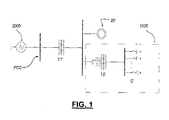
- Figure 1 shows a reactive power compensator 1000 according to the invention, connected in parallel to a wind power generator device 20' with a squirrel-cage induction machine.
- the assembly formed by said wind generator device 20' and said reactive power compensator 1000 according to the invention is connected to the electrical power grid 2000 by a common connection point PCC, with an intermediate transformer T1'.
- Said reactive power compensator 1000 comprises a capacitor array C' and a transformer with a variable transformation ratio or transformed T2'.
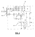
- Figure 2 shows an assembly 10 comprising a wind power generator device 20 provided with a reactive power compensator according to the invention, said assembly 10 being connected to the power grid 100 by a common connection point PCC.
- assembly 10 can comprise several wind power generator device 20, all of which are coupled in parallel to the same reactive power compensator according to the invention, also without being out of the scope of the present invention.
- figure 1 shows an assembly 10 including, on one hand, a wind power generator device 20 with its wind turbine A itself and its wind power injection line B with its polyphasic transformer TP (usually in the form of an electronic converter) and circuit breaker D1 and, on the other hand, a reactive power compensator according to the invention.
- a wind power generator device 20 with its wind turbine A itself and its wind power injection line B with its polyphasic transformer TP (usually in the form of an electronic converter) and circuit breaker D1 and, on the other hand, a reactive power compensator according to the invention.
- TP polyphasic transformer
- Said reactive power compensator is connected to the common connection point PCC in parallel to said wind power generator device 20 and comprises, starting from the common connection point PCC, a first fuse P1, a tri-phasic measurement transformer TM1 (formed by three mono-phasic transformers) and a second fuse P2, followed by three lines L1, L2 and L3a in radial disposition, each of which includes a fuse, respectively P3, P4 and P5.
- Said lines L1, L2 and L3a being in common with a line 3b that arrives from a measurement current transformer T1 interposed between the common connection point PCC and said wind power generator device 20, respectively generate a signal M1 with voltage V1, a signal M2 with voltage slope dV/dt and a signal M3 with reactive power Qr.
- These signals are fed via each of the lines L1, L2 and L3a+L3b to the control means materialised in this embodiment in a microcomputer 30.
- Said microcomputer 30 in turn supplies a signal M5 via a line L5 to the power means 40.
- Said power means 40 include a transformer that basically comprises, as is usual, a set of thyristors in antiparallel, labelled as a whole by the number 50, and an inductor 60.
- Said third branch is connected to said wind power generator device 20 with an intermediate circuit that includes, starting from said power means 40, a transformer T2 from which leave two shunts: a shunt S1 that ends in an intermediate point between said polyphasic transformer TP and the wind generator A itself, and a shunt S2 that ends in the circuit breaker D1.
- Said shunt S1 includes a circuit breaker D2 and said shunt S2 includes a numerical overcurrent protection device 70, a third shunt S3 being provided that connects said numerical overcurrent protection device 70 and said circuit breaker D2.
- This voltage dip has a voltage profile U represented by a continuous line in the graph of figure 2 , showing a time t 0 of instantaneous voltage drop (in which the voltage falls to 20% of the nominal value), an interval t 0 -t 1 (in which the voltage remains at 20% of the nominal voltage), a first phase t 1 -t 2 of recovery of the voltage (in which it rises to 80% of the nominal voltage) and a second phase t 2 -t of voltage recovery (in which it rises to its nominal value), where the duration of the first phase t 1 -t 2 is less than the duration of the second phase t 2 -t.
- Figure 3 represents the profile of the voltage V supplied by said power means 40, superimposed with a broken line on the voltage dip shown in figure 2 for comparison purposes. In this embodiment it is assumed that the power means 40 are not supplying power to the system at the time in which the voltage dip represented begins.
- said power means 40 increase their voltage when they are acted upon by the microcomputer 30 that detects in real time (by signals M1, M2 and M3) the start of the fault that leads to the voltage dip at the time to. Specifically, after a time t 0 ' included in the interval t 0 -t 1 , said power means 40 begin to provide gradually, in correspondence with the number of activated elements of the array of capacitors C, the reactive power needed to restore the voltage at the common connection point PCC, the voltage V reaching the nominal value Vn of the power means 40 (and therefore in this example also the nominal value Un of the power grid) at a time t 1 ' included in the interval t 1 -t 2 .
- said microcomputer 30 calculates the reactive power demanded by the power grid and the wind power generator device 20, based on said signal M3, so that the power means 40 operate as a conventional and discrete compensator of reactive powers.
- said microcomputer 30 acts on said power means 40 to supply the reactive power needed so that, on one hand, the induction units incorporated in said wind power generator device 20 remain substantially magnetised and, on the other hand, reactive power is supplied to the common connection point PCC to avoid consuming reactive power from the power grid at any time.
- the reactive power compensator according to the invention returns to the aforementioned configuration in which it operates again as a conventional and discrete reactive power compensator.
Landscapes
- Engineering & Computer Science (AREA)
- Power Engineering (AREA)
- Life Sciences & Earth Sciences (AREA)
- Sustainable Development (AREA)
- Sustainable Energy (AREA)
- Chemical & Material Sciences (AREA)
- Combustion & Propulsion (AREA)
- Mechanical Engineering (AREA)
- General Engineering & Computer Science (AREA)
- Control Of Electrical Variables (AREA)
- Supply And Distribution Of Alternating Current (AREA)
- Control Of Eletrric Generators (AREA)
Applications Claiming Priority (2)
| Application Number | Priority Date | Filing Date | Title |
|---|---|---|---|
| ES200602074A ES2289954B1 (es) | 2006-07-31 | 2006-07-31 | Compensador de energia reactiva. |
| PCT/ES2007/000472 WO2008015306A2 (fr) | 2006-07-31 | 2007-07-31 | Compensateur d'énergie réactive |
Publications (1)
| Publication Number | Publication Date |
|---|---|
| EP2071691A2 true EP2071691A2 (fr) | 2009-06-17 |
Family
ID=38961572
Family Applications (1)
| Application Number | Title | Priority Date | Filing Date |
|---|---|---|---|
| EP07822880A Withdrawn EP2071691A2 (fr) | 2006-07-31 | 2007-07-31 | Compensateur d'energie reactive |
Country Status (3)
| Country | Link |
|---|---|
| EP (1) | EP2071691A2 (fr) |
| ES (1) | ES2289954B1 (fr) |
| WO (1) | WO2008015306A2 (fr) |
Cited By (5)
| Publication number | Priority date | Publication date | Assignee | Title |
|---|---|---|---|---|
| US8063500B2 (en) | 2010-02-18 | 2011-11-22 | Mitsubishi Heavy Industries, Ltd. | Maintenance operation method for wind turbine generator and wind turbine generator |
| CN104819107A (zh) * | 2015-05-13 | 2015-08-05 | 北京天源科创风电技术有限责任公司 | 一种风电机组功率曲线异常漂移的诊断方法及系统 |
| CN109066818A (zh) * | 2018-08-30 | 2018-12-21 | 国家电网公司华东分部 | 同步发电机/调相机的动态无功储备计算方法 |
| RU2711537C1 (ru) * | 2018-12-28 | 2020-01-17 | Дмитрий Иванович Панфилов | Статический компенсатор реактивной мощности |
| RU2786130C1 (ru) * | 2022-08-08 | 2022-12-19 | Дмитрий Иванович Панфилов | Статический компенсатор реактивной мощности |
Families Citing this family (4)
| Publication number | Priority date | Publication date | Assignee | Title |
|---|---|---|---|---|
| CN102738807B (zh) * | 2012-06-20 | 2013-11-20 | 吉林省电力有限公司电力科学研究院 | 风电场集中接入公用变电站的全站无功优化控制方法 |
| ES2539534B1 (es) * | 2014-10-03 | 2016-02-19 | Jaime MARTÍN ASENSIO | Sistema recuperador de energía |
| CN105548741B (zh) * | 2015-12-04 | 2019-06-04 | 中国电力科学研究院 | 一种用于风电场无功补偿装置低电压运行能力的检测方法 |
| CN106374503B (zh) * | 2016-09-12 | 2018-12-07 | 珠海格力电器股份有限公司 | 电压跌落、电气设备并网处理方法、装置及系统 |
Family Cites Families (4)
| Publication number | Priority date | Publication date | Assignee | Title |
|---|---|---|---|---|
| JP2000041338A (ja) * | 1998-05-18 | 2000-02-08 | Nissin Electric Co Ltd | 系統連系装置 |
| JP2003199252A (ja) * | 2001-12-27 | 2003-07-11 | Kansai Electric Power Co Inc:The | 分散電源システム及びその制御方法 |
| JP2004320859A (ja) * | 2003-04-14 | 2004-11-11 | Hitachi Ltd | 無効電力補償装置 |
| ES2245608B1 (es) * | 2004-06-30 | 2007-03-01 | Gamesa Eolica S.A. | Procedimiento y dispositivo para evitar la desconexion de un parque de generacion de energia electrica de la red. |
-
2006
- 2006-07-31 ES ES200602074A patent/ES2289954B1/es not_active Expired - Fee Related
-
2007
- 2007-07-31 WO PCT/ES2007/000472 patent/WO2008015306A2/fr active Application Filing
- 2007-07-31 EP EP07822880A patent/EP2071691A2/fr not_active Withdrawn
Non-Patent Citations (1)
| Title |
|---|
| See references of WO2008015306A2 * |
Cited By (9)
| Publication number | Priority date | Publication date | Assignee | Title |
|---|---|---|---|---|
| US8063500B2 (en) | 2010-02-18 | 2011-11-22 | Mitsubishi Heavy Industries, Ltd. | Maintenance operation method for wind turbine generator and wind turbine generator |
| AU2010201620B2 (en) * | 2010-02-18 | 2012-03-29 | Mitsubishi Heavy Industries, Ltd. | Maintenance operation method for wind turbine generator and wind turbine generator |
| AU2010201620B8 (en) * | 2010-02-18 | 2012-05-03 | Mitsubishi Heavy Industries, Ltd. | Maintenance operation method for wind turbine generator and wind turbine generator |
| CN104819107A (zh) * | 2015-05-13 | 2015-08-05 | 北京天源科创风电技术有限责任公司 | 一种风电机组功率曲线异常漂移的诊断方法及系统 |
| CN104819107B (zh) * | 2015-05-13 | 2017-07-28 | 北京天源科创风电技术有限责任公司 | 一种风电机组功率曲线异常漂移的诊断方法及系统 |
| CN109066818A (zh) * | 2018-08-30 | 2018-12-21 | 国家电网公司华东分部 | 同步发电机/调相机的动态无功储备计算方法 |
| RU2711537C1 (ru) * | 2018-12-28 | 2020-01-17 | Дмитрий Иванович Панфилов | Статический компенсатор реактивной мощности |
| RU2791058C1 (ru) * | 2022-07-15 | 2023-03-02 | Дмитрий Иванович Панфилов | Статический компенсатор реактивной мощности |
| RU2786130C1 (ru) * | 2022-08-08 | 2022-12-19 | Дмитрий Иванович Панфилов | Статический компенсатор реактивной мощности |
Also Published As
| Publication number | Publication date |
|---|---|
| ES2289954B1 (es) | 2009-02-01 |
| WO2008015306A2 (fr) | 2008-02-07 |
| WO2008015306A3 (fr) | 2008-03-20 |
| ES2289954A1 (es) | 2008-02-01 |
Similar Documents
| Publication | Publication Date | Title |
|---|---|---|
| EP2071691A2 (fr) | Compensateur d'energie reactive | |
| DE102010060380B3 (de) | Notbetriebsfähige Pitchmotor-Antriebsschaltung | |
| US8120932B2 (en) | Low voltage ride through | |
| US7978445B2 (en) | Systems and apparatus relating to wind turbine electrical control and operation | |
| US6879062B2 (en) | Electrical substation | |
| EP1841050B1 (fr) | Procédé pour convertir une tension continue en une tension triphasée | |
| CN101682286B (zh) | 用于在暂态电网电压变化下运行双馈异步电机的方法和设备 | |
| DK2580836T3 (en) | Wind energy plant and method for operating a wind power plant | |
| CN107076118B (zh) | 用于模块化串式转换器的风力涡轮机转换器控制 | |
| EP2293431B1 (fr) | Procédé et système de commande d'une installation éolienne en cas de défaillances du réseau | |
| US9634490B2 (en) | Dynamic voltage restoration system and method | |
| JP4546486B2 (ja) | 電力ネットワーク | |
| MX2007006440A (es) | Metodo para controlar una turbina eolica conectada a una red de distribucion electrica. | |
| CA2891065C (fr) | Dispositif excitateur statique pour generateurs | |
| KR102383907B1 (ko) | 브러시리스 영구 자석 발전기와 보조 전압원 정전위 여자기 | |
| CN103560680A (zh) | 双馈感应发电机变流器以及用于改进电网故障穿越的方法 | |
| CN101682192A (zh) | 影响调速发电机发电的方法和系统 | |
| EP2311165A1 (fr) | Maintien d'alimentation en cas de sous-tension | |
| Lee et al. | Short-circuit protection for MV & LVDC grid | |
| Rohouma et al. | Reactive power compensation of time-varying load using capacitor-less D-STATCOM | |
| CN110649565B (zh) | 一种高铁再生制动能量回馈系统的保护方法 | |
| WO2016165739A1 (fr) | Système d'énergie renouvelable, parc d'énergie renouvelable, procédé de fonctionnement d'un système d'énergie renouvelable, et procédé de fonctionnement d'un parc d'énergie renouvelable | |
| CN210629117U (zh) | 一种具备高电压穿越功能的风电机组孤岛切出装置 | |
| JP2002142365A (ja) | 直流送電設備 | |
| CA2757353A1 (fr) | Alimentation en energie d'un reseau electrique |
Legal Events
| Date | Code | Title | Description |
|---|---|---|---|
| PUAI | Public reference made under article 153(3) epc to a published international application that has entered the european phase |
Free format text: ORIGINAL CODE: 0009012 |
|
| 17P | Request for examination filed |
Effective date: 20090226 |
|
| AK | Designated contracting states |
Kind code of ref document: A2 Designated state(s): AT BE BG CH CY CZ DE DK EE ES FI FR GB GR HU IE IS IT LI LT LU LV MC MT NL PL PT RO SE SI SK TR |
|
| AX | Request for extension of the european patent |
Extension state: AL BA HR MK RS |
|
| DAX | Request for extension of the european patent (deleted) | ||
| STAA | Information on the status of an ep patent application or granted ep patent |
Free format text: STATUS: THE APPLICATION IS DEEMED TO BE WITHDRAWN |
|
| 18D | Application deemed to be withdrawn |
Effective date: 20120201 |