EP2071661A1 - Ensemble de compensation de l'expansion thermique - Google Patents
Ensemble de compensation de l'expansion thermique Download PDFInfo
- Publication number
- EP2071661A1 EP2071661A1 EP09005083A EP09005083A EP2071661A1 EP 2071661 A1 EP2071661 A1 EP 2071661A1 EP 09005083 A EP09005083 A EP 09005083A EP 09005083 A EP09005083 A EP 09005083A EP 2071661 A1 EP2071661 A1 EP 2071661A1
- Authority
- EP
- European Patent Office
- Prior art keywords
- thermal expansion
- manifold
- assembly
- lever
- compensation
- Prior art date
- Legal status (The legal status is an assumption and is not a legal conclusion. Google has not performed a legal analysis and makes no representation as to the accuracy of the status listed.)
- Granted
Links
- 230000000712 assembly Effects 0.000 title abstract description 17
- 238000000429 assembly Methods 0.000 title abstract description 17
- 238000004873 anchoring Methods 0.000 claims abstract description 41
- 238000006073 displacement reaction Methods 0.000 claims abstract description 12
- 239000000463 material Substances 0.000 description 27
- 239000012528 membrane Substances 0.000 description 21
- 230000007246 mechanism Effects 0.000 description 18
- 230000000452 restraining effect Effects 0.000 description 17
- 229910001374 Invar Inorganic materials 0.000 description 14
- 238000013461 design Methods 0.000 description 13
- 229910052782 aluminium Inorganic materials 0.000 description 11
- XAGFODPZIPBFFR-UHFFFAOYSA-N aluminium Chemical compound [Al] XAGFODPZIPBFFR-UHFFFAOYSA-N 0.000 description 11
- 230000000694 effects Effects 0.000 description 8
- 230000008859 change Effects 0.000 description 7
- 230000008602 contraction Effects 0.000 description 7
- 230000033001 locomotion Effects 0.000 description 7
- 229910000831 Steel Inorganic materials 0.000 description 6
- 238000013459 approach Methods 0.000 description 6
- 230000009021 linear effect Effects 0.000 description 6
- 239000010959 steel Substances 0.000 description 6
- 230000001965 increasing effect Effects 0.000 description 5
- 238000000034 method Methods 0.000 description 5
- 230000009977 dual effect Effects 0.000 description 4
- 230000006870 function Effects 0.000 description 4
- 238000004519 manufacturing process Methods 0.000 description 4
- 230000004044 response Effects 0.000 description 4
- 239000000243 solution Substances 0.000 description 4
- 230000009471 action Effects 0.000 description 3
- 239000000470 constituent Substances 0.000 description 3
- 230000035515 penetration Effects 0.000 description 3
- 238000000926 separation method Methods 0.000 description 3
- 230000003321 amplification Effects 0.000 description 2
- 238000005452 bending Methods 0.000 description 2
- 230000005540 biological transmission Effects 0.000 description 2
- 238000006243 chemical reaction Methods 0.000 description 2
- 239000002131 composite material Substances 0.000 description 2
- 230000007423 decrease Effects 0.000 description 2
- 230000001419 dependent effect Effects 0.000 description 2
- 230000005489 elastic deformation Effects 0.000 description 2
- 230000001939 inductive effect Effects 0.000 description 2
- 238000002347 injection Methods 0.000 description 2
- 239000007924 injection Substances 0.000 description 2
- 238000012986 modification Methods 0.000 description 2
- 230000004048 modification Effects 0.000 description 2
- 238000003199 nucleic acid amplification method Methods 0.000 description 2
- 230000006641 stabilisation Effects 0.000 description 2
- 238000011105 stabilization Methods 0.000 description 2
- 239000010935 stainless steel Substances 0.000 description 2
- 229910001220 stainless steel Inorganic materials 0.000 description 2
- 230000035882 stress Effects 0.000 description 2
- 230000008646 thermal stress Effects 0.000 description 2
- 229910000851 Alloy steel Inorganic materials 0.000 description 1
- 230000008901 benefit Effects 0.000 description 1
- 230000006835 compression Effects 0.000 description 1
- 238000007906 compression Methods 0.000 description 1
- 238000010276 construction Methods 0.000 description 1
- 238000001816 cooling Methods 0.000 description 1
- 230000008878 coupling Effects 0.000 description 1
- 238000010168 coupling process Methods 0.000 description 1
- 238000005859 coupling reaction Methods 0.000 description 1
- 230000007812 deficiency Effects 0.000 description 1
- 238000010586 diagram Methods 0.000 description 1
- 239000006185 dispersion Substances 0.000 description 1
- 230000004907 flux Effects 0.000 description 1
- 238000010438 heat treatment Methods 0.000 description 1
- 230000006872 improvement Effects 0.000 description 1
- 230000010354 integration Effects 0.000 description 1
- 239000007769 metal material Substances 0.000 description 1
- VNWKTOKETHGBQD-UHFFFAOYSA-N methane Chemical class C VNWKTOKETHGBQD-UHFFFAOYSA-N 0.000 description 1
- 230000003094 perturbing effect Effects 0.000 description 1
- 238000005191 phase separation Methods 0.000 description 1
- 230000021715 photosynthesis, light harvesting Effects 0.000 description 1
- 230000008569 process Effects 0.000 description 1
- 230000035945 sensitivity Effects 0.000 description 1
- 229910001285 shape-memory alloy Inorganic materials 0.000 description 1
- 238000001228 spectrum Methods 0.000 description 1
- 238000006467 substitution reaction Methods 0.000 description 1
- 238000012360 testing method Methods 0.000 description 1
- 238000012546 transfer Methods 0.000 description 1
- 210000001364 upper extremity Anatomy 0.000 description 1
Images


Classifications
-
- H—ELECTRICITY
- H01—ELECTRIC ELEMENTS
- H01P—WAVEGUIDES; RESONATORS, LINES, OR OTHER DEVICES OF THE WAVEGUIDE TYPE
- H01P1/00—Auxiliary devices
- H01P1/30—Auxiliary devices for compensation of, or protection against, temperature or moisture effects ; for improving power handling capability
Definitions
- the embodiments described herein relate to multiplexers and more particularly to a thermal expansion compensation assembly for manifolds.
- FIG. 1 illustrates a conventional output multiplexer 5 and shows the filters 7, comprised of resonant structures, and the manifold 9 into which signals are injected and combined.
- the filters 7 interface directly with the manifold 9, without any intermediate provision to isolate the filter function from the combining function. This form achieves considerable economies of size and power efficiency, but results in a highly complex design that must be optimized and aligned as a whole because of the extreme interdependence of all constituent parts. Accordingly, output multiplexers are inherently sensitive structures.
- Output multiplexers have been traditionally fabricated from very low expansion steel alloys of which Invar, with a coefficient of thermal expansion (CTE) near 1 part per million per Celsius degree (ppm/C°), is most common.
- CTE coefficient of thermal expansion
- ppm/C° 1 part per million per Celsius degree
- Invar Invar
- power levels upwards of 450 Watts per channel
- Invar exhibits poor thermal conduction properties, which lead to self-defeating high temperatures.
- Temperatures of some extant designs approach the limits of the output multiplexer materials.
- Alternate low CTE materials, such as carbon fiber composites share this conduction deficiency.
- Invar has undesirably high mass density.
- Aluminum is a preferred material in general spacecraft application because of its lightness, strength, and excellent thermal conductivity.
- aluminum also has a noteably high CTE of 23.4 ppm/C°, which is untenable in a conventional output multiplexer application.
- an aluminum output multiplexer is highly desirable in a high power regime and is well suited in every aspect except in the dimensional stability of the radio frequency boundaries. What is needed is a means of compensating for the radio frequency effects of thermal expansion associated with an aluminum output multiplexer.
- a manifold compensation assembly for thermal compensation of a manifold enclosing a rectangular waveguide, having thin and compliant narrow walls and rigid broad walls, said manifold compensation assembly comprising:
- FIG. 1 is a conventional prior art output multiplexer
- FIG. 2A is a front perspective view of an exemplary embodiment of a filter compensation assembly
- FIG. 2B is top rear perspective view of the filter compensation assembly of FIG. 2A ;
- FIG. 3A is a side perspective view of two filter compensation assemblies of FIG. 2A installed on an exemplary cavity filter assembly;
- FIG. 3B is a front cross-sectional view of two filter compensation assemblies of FIG. 2A installed on a cavity filter assembly in the absence of thermal expansion;
- FIG. 3C is a front cross-sectional view of the filter compensation assembly of FIG. 2A installed on a cavity filter assembly in the presence of thermal expansion;
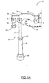
- FIG. 4 is a front perspective view of an exemplary embodiment of a manifold compensation assembly
- FIG. 5A is a side perspective view of two of the manifold compensation assemblies of FIG. 4 and two spreaders beam installed on a exemplary manifold;
- FIG. 5B is a front cross-sectional view of the manifold compensation assembly of FIG. 4 and two beam spreaders installed on a manifold in the absence of thermal expansion;
- FIG. 5C is a front cross-sectional view of the manifold compensation assembly of FIG. 4 and two beam spreaders installed on a manifold in the presence of thermal expansion;
- FIG. 6 is a graphical diagram that illustrates the performance of the exemplary compensated cavity filter of FIG. 3A .
- FIGS. 2A and 2B illustrate a filter compensation assembly 10.
- the filter compensation assembly 10 includes a lever element 12, a thermal expansion element 16, and an anchoring element 18.
- the lever element 12 is pivotally coupled to a membrane section 14 associated with a cavity end wall, the thermal expansion element 16 and the anchoring element 18.
- the filter compensation assembly 10 is designed to deform the membrane section 14 associated with an end wall of a cavity filter assembly 30 in order to compensate for (i.e. negate) the effects of thermal expansion, as will be described in detail.
- the lever element 12 is a substantially flat section with three pivot openings formed therein located at pivot points A, B and C. Accordingly, the lever element 12 is designed to be coupled to the membrane section 14, the anchoring element 18 and the thermal expansion element 16 at the three pivot points A, B and C, respectively as shown in FIG. 2A . Specifically, the lever element 12 is pivotally coupled to the membrane section 14 (of the end wall of a filter cavity assembly 30 ) at pivot point A through a pivoting connector 20. The lever element 12 is pivotally coupled to the anchoring element 18 at pivot point B through a pivoting connector 22. Finally, the lever element 12 is pivotally coupled at pivot point C to the thermal expansion element 16 using a pivoting connector 24.
- the lever element 12 is preferably manufactured out of a material with high tensile strength and stiffness (e.g. steel).
- the lever element 12 is sized sufficiently large to have negligible elastic deformation under the reaction loads from the cavity end wall. In this way, the compensation rate is a function only of the geometry and the CTE of constituent parts and therefore is predictable and controllable to a high precision.
- Any structural material of suitable stiffness may be employed with ANSI 440-C stainless steel being preferred because of its superior bearing qualities at the pivot points A, B and C.
- the lever element 12 is slotted at the end at which it pivotally connects to membrane section 14 ( FIGS. 3B and 3C ) to allow for radial expansion of the filter cavity assembly 30 and to allow the filter compensation assembly 10 to be fitted after filter tuning and stabilization.
- the coefficient of thermal expansion (CTE) of the lever element 12 is inconsequential since the slotted pivot hole at pivot A ( FIGS. 3B, 3C ) is designed to accommodate the radial expansion of the filter cavity assembly 30. Accordingly, the lever element 12 is designed to predictably transfer the relative motion of the thermal expansion element 16 to the membrane section 14 of the cavity filter assembly 30.
- the thermal expansion element 16 is coupled at pivot point C to the lever element 12 through the pivoting connector 24 ( FIG. 2A ).
- the thermal expansion element 16 is preferably a two-piece element that has a top section 17 and a bottom section 19 which are coupled together, preferably by threading the top section 17 inside the bottom section 19 and securing the engagement using a suitable locking device 21 such as a jam-nut (e.g. standard screw and bolt fastener).
- a suitable locking device 21 such as a jam-nut (e.g. standard screw and bolt fastener).
- the top section 17 and the bottom section 19 are each preferably rod-shaped, however it should be understood that they could be of any suitable shape and/or cross-section.
- the top section 17 and bottom section 19 of the thermal expansion element 16 are both manufactured from material or materials that have a relatively low coefficient of thermal expansion (CTE) in relation to the cavity filter assembly 30 as will be discussed.
- the top section 17 of thermal expansion element 16 is preferably manufactured from a material such as Invar having a coefficient of thermal expansion preferably in the range of 0.7 to 1.5 ppm/C°.
- the bottom section 19 is preferably manufactured of the same material (e.g., Invar).
- the bottom section 19 has a locating feature such as a shoulder (not shown) formed at the end of the bottom section 19 and which is adapted along with an mounting element 26 to securely couple the filter compensation assembly 10 to the bottom portion of the housing of a cavity filter assembly 30.
- a locating feature such as a shoulder (not shown) formed at the end of the bottom section 19 and which is adapted along with an mounting element 26 to securely couple the filter compensation assembly 10 to the bottom portion of the housing of a cavity filter assembly 30.
- a separate mounting element 26 in the form of a threaded plug assures that the anchoring shoulder and land surface of the anchoring boss of cavity filter assembly 30 remain in intimate contact at all times even when the thermal expansion element is in compression as would be the case at low temperature.
- Mounting element 26 is preferably manufactured from conventional steel for threaded fasteners, the CTE having minimal significance.
- the two-piece design of the thermal expansion element 16 allows for the necessary assembly adjustments to mitigate the effect of a combination of manufacturing tolerances and permits the identical thermal expansion element to be applied to a range of different cavity lengths. While the thermal expansion element 16 could be of unitary design, the two-piece construction is highly advantageous because of the adjustments permitted.
- top section 17 and the bottom section 19 are described above as both being manufactured out of a common material such as Invar, the inventors have observed that it is difficult to thread Invar material into Invar material because of the softness of the material.
- An alternative is to make one of the top section 17 and the bottom section 19 out of a material such as Invar and design it as long as possible dimensionally and make the companion part out of a harder material (e.g. steel) and as short dimensionally as possible.
- the underlying concept of this strategy would be that the short part would be optimized for strength but contributes little absolute expansion because of the minimum length.
- Another alternative for the thermal compensation element 16 to be manufactured as a single piece with an external thread positioned at the end that corresponds to the housing restraining element 32. A threaded nut fattener is then used to secure the thermal compensation element 16 to the restraining element 32 with adjustment provided by inserting shims under the fastener.
- thermal expansion element 16 is provided outside the cavity filter assembly 30 and is not strongly bound to the cavity in terms of heat flow. Therefore the thermal expansion element 16 can deviate in temperature from the cavity filter assembly 30 depending on application specific thermal boundary conditions. For this reason, the preferred material for the thermal expansion element 16 is Invar that is sufficiently near zero CTE that the temperature deviation is not of significant consequence. Thermal expansion element 16 can be manufactured out of higher CTE but this requires custom design.
- the relatively long dimension of the thermal expansion element 16 in relation to the other elements of the filter compensation assembly 10 reduces the sensitivity of the filter compensation assembly 10 to manufacturing tolerances. This is because the compensation rate is proportional to the length of the length of thermal expansion element 16.
- the only other critical elements to maintaining controlled compensation rate are the locations of the pivot points A, B, and C on lever 12, which are can be readily controlled.
- the anchoring element 18 is utilized to secure the filter compensation assembly 10 to the housing of the cavity filter assembly 30 as will be discussed.
- the anchoring element 18 is preferably a relatively short rod, however, it should be understood that anchoring element 18 could be of any suitable shape and/or cross-section.
- the anchoring element 18 includes a restraining element 28 which is positioned near the end of the anchoring element 18 and which is adapted to securely couple the filter compensation assembly 10 to the top portion of a filter housing at pivot point B.
- the anchoring element 18 is preferably manufactured from a material with substantial tensile strength (e.g. steel) to ensure stability.
- the restraining element 28 is sufficiently small that the CTE of the material does not significantly affect the compensation mechanism.
- FIGS. 3A , 3B and 3C illustrate the application of two identical filter compensation assemblies 10 to a Ku band four pole (two dual mode cavities) filter assembly 30.
- FIGS. 3A and 3B illustrate the baseline configuration (i.e. in the absence of thermal expansion) of two filter compensation assemblies 10 as implemented within a Ku band four pole (two dual mode cavities) filter cavity assembly 30.
- FIG. 3C illustrates two filter compensation assemblies 10 as implemented within a Ku band four pole (two dual mode cavities) filter cavity assembly 30 in the presence of thermal expansion.
- FIGS. 3B and 3C are cross-sectional views with the sectional plane being in the middle of the lever element 12.
- each filter compensation assembly 10 provides a driving mechanism that consists of the thermal expansion element 16 having a low CTE which in the presence of temperature increase, causes the lever element 12 to bear down onto the membrane section 14 (i.e. the cavity end wall) of the filter cavity assembly 30. Conversely, in the presence of a temperature decrease, the mechanism causes the lever element 12 to pull up on the membrane section 14.
- the thermal expansion element 16 when the thermal expansion element 16 is installed within the filter assembly 30, the thermal expansion element 16 is positioned substantially parallel to the longitudinal axis of the resonant cavities of the filter assembly 30. Also, the thermal expansion element 16 is substantially equal in length to the filter cavity.
- the mounting element 26 on the bottom section 19 of the thermal expansion element 16 is used to secure the filter compensation assembly 10 to the bottom housing of cavity filter assembly 30 and is specifically secured within a restraining element 32 as shown in FIG. 3A .
- the anchoring element 18 is used to pivotally secure the filter compensation assembly 10 to the top portion of the housing of cavity filter assembly 30 through a pivoting connector 22 at pivot point B.
- the anchoring element 18 is positioned and secured within a restraining element 34 of filter assembly 30 through the use of the restraining element 28.
- the anchoring elements can be made integral with the restraining element 34 of the filter assembly by designing the restraining element to incorporate a pivoting connection point 22. In practice, however, separate restraining elements 28 and 34 are more practical to ease assembly and to afford the use of high stiffness material at the pivoting connection point 22.
- the anchoring element 18 is a threaded shaft passing through a hole in the restraining feature 34 secured with a restraining element 28 that is a standard nut.
- lever element 12 is pivotally coupled to the membrane section 14 of the cavity filter assembly 30 through pivoting connector 20 at pivoting point A.
- the lever element 12 is pivotally coupled to anchoring element 18 at pivot point B through pivoting connector 22. Also, the lever element 12 is pivotally coupled to the thermal expansion element 16 at an intermediate pivot point C using pivoting connector 24. Also, the lever element 12 is pivotally coupled to the center region of a membrane section 14 of the filter cavity assembly 30 at pivot point A using the pivoting connector 20.
- the filter compensation assembly 10 can be fitted after filter tuning and stabilization.
- the initial alignment and adjustment of a filter often requires disassembly to access internal features, which process is greatly abetted by not requiring the integration of compensation at these initial stages.
- the thermal expansion element 16 will expand less relative to the aluminum cavity filter assembly 30 ( FIG. 3C ). As the aluminum cavity filter assembly 30 expands, the thermal expansion element 16 will remain relatively unaffected by the increase in operating temperature. Simultaneously, the thermal expansion element 16 will continue to be held in place by anchoring element 18 through lever element 12 and pivot points B and C.
- the lever element 12 Since the anchoring element 18 anchors one end of the lever element 12 at pivot point B, and since the thermal expansion element 16 does not expand as readily as the cavity filter assembly 30, the lever element 12 will exert downwards pressure on the membrane section 14 at pivot point A (as illustrated by arrow A in FIG. 3C ). That is, in the presence of a temperature increase, the membrane section 14 is deformed by the lever element 12 at pivot point A in a manner that alters the effective length of the filter assembly cavity sufficiently to negate the resonant frequency change due to thermal expansion of the filter assembly cavity.
- the filter compensation assembly 10 has freely moving pivot points that permit the mechanism to be arbitrarily stiff relative to the membrane section 14 and therefore highly deterministic in performance.
- the prior art compensation assemblies employ bi-metal material or flexure structures to deform cavity end walls. In these designs, the cavity wall position is determined by an equilibrium of opposing elastic forces and specifically the restoring force of the cavity wall and the deforming forces of the thermally induced stresses. The precision of these kinds of compensation assemblies is dependent on the stiffness of the elements that are difficult to control in manufacture.
- the design of the anchoring element 18 determines the degree of mechanical amplification at issue according to conventional principles of lever mechanical operation. Specifically, the difference between the lengthwise thermal expansion (or contraction) of the cavity filter assembly 30 and the expansion (or contraction) of the thermal expansion element 16 imparts a countervailing and larger displacement towards (or away from) the center of membrane section 14 of a magnitude equal to the expansion of the cavity filter assembly 14 times the ratio of the between pivot-point lengths B-A to B-C.
- This lever mechanism of the filter compensation assembly 10 amplifies the differential expansion (or contraction) of the various assembly elements, allowing for larger displacements than permitted in prior art devices, thereby accommodating greater temperature excursions that are inherent in high power applications.
- both the motion inducing element e.g. the low CTE element
- the target element e.g. membrane
- the main appeal of the present approach is that the motion inducing element is highly rigid, with all rotations achieved through pivots, so that the amount of mechanical compensation results from simple geometry calculations, such as the lever ratio, instead of a balance between opposing spring forces, which can be notoriously inconsistent in respect of material properties and manufacturing dimensions.
- the ability to amplify the relative size changes of the relevant elements of the filter compensation assembly 10 significantly extends the operating range of the mechanism in comparison with the prior art.
- the mechanical action of the filter compensation assembly 10 is substantially more linear in nature than is the case in prior art compensation assemblies.
- the resonant frequency of a cylindrical cavity is proportional to the scale, therefore, the proportional change in frequency with temperature is precisely the same as the CTE of the material from which it is made.
- the resonant frequency is not proportional to length alone, but over the range of operation of the present invention, very closely approximates a linear relationship. Therefore, a compensation method where the compensation is directly proportional to expansion represents a preferred solution. Accordingly, the filter compensation assembly 10 is more effective in controlling the linear effects of thermal expansion then other conventional non-linear solutions.
- FIG. 4 illustrates a manifold compensation assembly 50 in one exemplary embodiment.
- the manifold compensation assembly 50 includes first and second lever elements 52a and 52b, a thermal expansion element 56, first and second anchoring elements 54a and 54b.
- the first and second lever elements 52a and 52b are pivotally coupled to the first and second anchoring elements 54a and 54b and to the thermal expansion element 56 and adapted to also be pivotally coupled to the narrow wall 84 of the manifold 80 through (optional) spreader beams 86 ( FIG. 5A , 5B and 5C ).
- the manifold compensation assembly 50 is designed to deform the narrow wall 84 of the manifold 80 in the presence of increased operating temperatures, in order to negate the effects of thermal expansion, as will be described in detail.
- first and second lever elements 52a and 52b are substantially flat sections with three pivot openings defined within and located at pivot points D, E and F and D', E' and F', respectively.
- Each of the first and second lever elements 52a and 52b are adapted to be coupled at pivot points D and D', respectively to a spreader beam 86 mounted on a narrow wall 84 of a manifold 80 ( FIG. 5A , 5B and 5C ) through pivoting connectors 60.
- Each of the first and second lever elements 52a and 52b are also coupled at pivot points E and E' to the first and second anchoring elements 54a and 54b through pivoting connectors 64 such that the upper extremities of the first and second lever elements 52a and 52b are constrained by the first and second anchoring elements 54a and 54b, respectively.
- the first and second lever elements 52a and 52b are coupled at pivot points F and F', respectively to the thermal expansion element 56 through pivoting connectors 62.
- the first and second lever elements 52a and 52b are preferably manufactured out of a material with very high tensile strength and stiffness (e.g. steel).
- the lever elements 52a and 52b are sized sufficiently large to have negligible elastic deformation under the reaction loads from the manifold wall. In this way, the compensation rate is a function only of the geometry and the CTE of constituent parts and therefore is predictable and controllable to a high precision.
- the coefficient of thermal expansion (CTE) of the lever elements 52a and 52b is inconsequential because of the slotted pivot holes at the pivot points D and D' which are designed to accommodate any in-plane expansion of the manifold narrow wall. Any structural material of suitable stiffness may be employed with ANSI 440-C stainless steel being preferred because of its superior bearing qualities at the various pivot points.
- first anchoring element 54a is coupled to the first lever element 52a at pivot point E and the second anchoring element 54b is coupled to the second lever element 52b at pivot point E'.
- the first lever element 52a is coupled to the thermal expansion element 56 through a pivoting connector 62 at pivot point F and the second lever element 52b is coupled to the thermal expansion element 56 through a pivoting connector 62 at pivot point F'.
- first and second restraining elements 54a and 54b are shown as being separate, to permit a degree of adjustment in the mechanism, it should be understood that first and second restraining elements 54a and 54b could be replaced by a single restraining element or alternatively, could be realized as a feature of the rigid broad wall of the manifold structure.
- FIGS. 5B and 5C illustrate a cross-section which is taken through the center of the lever elements 52a and 52b. Both the restraining elements 54a and 54b and the thermal expansion element 56 thermal expansion element 56 have "forked ends" that surround the lever which are shown more markedly in FIG. 5C . It should be understood that the only physical connections between the lever elements 52a and 52b, the restraining elements 54a and 54b, and the thermal expansion element 56 are through pivot connections D, D', E, E', F, and F'.
- the thermal expansion element 56 is a substantially rectangular element and has openings formed therein at pivot points F and F' ( FIG. 4 ).
- the thermal expansion element 56 is coupled to and in between the first and second lever elements 52a and 52b at pivot points F and F' as shown.
- the thermal expansion element 56 is preferably manufactured from low CTE material such as Invar which has a range of 0.7 to 1.5 ppm/C°. A CTE close to zero is preferred in order to remove variability in performance if the expansion element 56 attains temperatures that are different from the manifold.
- the multiplexer manifold 80 of this exemplary illustration is an aluminum rectangular waveguide into which a plurality of signals are injected and combined into a composite signal.
- the manifold 80 is sensitive to thermal expansion which alters the electrical phase differential among signal injection points as shown.
- the manifold compensation assembly 50 is used to adjust the larger dimension of the rectangle section of the manifold 80 through controlled deformation of the narrow walls 84 (in a direction that is opposite to the thermal expansion) such that the phase separation of the injection points remains constant as the manifold 80 expands along its longitudinal axis.
- a plurality of manifold compensation assemblies 50 are deployed along the length of the manifold 80 to maintain uniform displacement over the operating length.
- two rigid steel spreader beams 86 are fitted to the narrow walls 84 of the manifold 80 ( FIGS. 5A , 5B and 5C ) to distribute the deforming (i.e. compensating) force provided by the manifold compensation assemblies 50 and to minimize the number of manifold compensation assemblies 50 required.
- the spreader beams 86 are rectangular beams having a length that is substantially equal to the length of the manifold.
- the spreader beams 86 each include an inside ridge 89 positioned next to the narrow wall 84 of the manifold 80.
- the inside ridge 89 is part of the manifold wall and is there to receive and attach to the spreader beams 86.
- a spreader beam 86 could be mounted to the manifold wall in order to implement manifold compensation assemblies 50, wherein the spreader beam 86 is free to push and pull on the manifold wall but constrained to maintain contact with the manifold wall.
- Each manifold compensation assembly 50 is positioned transverse to the length of the manifold such that the first and second lever elements 52a and 52b are located on opposite sides of the manifold 80.
- the first and second anchoring elements 54a and 54b are fixed to the manifold using standard fasteners.
- the first and second lever elements 52a and 52b have amplification which results from the relative spacing of the pivot points E, F, and D and E', F', and D', along the length of the first and second lever elements 52a.
- thermal expansion element 56 expands to a lesser degree than the first and second anchoring elements 54a and 54b, and the manifold 80 to which first and second anchoring elements 54a and 54b are rigidly fastened and form part. Accordingly, the first and second anchoring elements 54a and 54b force first and second lever elements 52a and 52b apart at pivot points E and E' by a first degree. Simultaneously, since the thermal expansion element 56 expands to a lesser degree than the first and second anchoring elements 54a and 54b, thermal expansion element 56 forces the first and second lever elements 52a and 52b apart to a second degree where the second degree is less than the first degree.
- first and second lever elements 52a and 52b exert deforming pressure inwards at pivot points D and D' onto the spreader beams 86 which then translates into inward pressure from the inside ridges 89 on the narrow walls 84 of the waveguide 80 as shown by the arrows D and D' in FIG. 5C .
- the manifold compensation assembly 50 has freely moving pivot points D, D', E, E', F, and F' that permit the temperature dependent mechanism to be arbitrarily stiff relative to the membrane section 84 and therefore highly deterministic in performance.
- the lever mechanism of the manifold compensation assembly 50 amplifies the differential expansion of the various assembly elements, allowing for larger displacements than permitted in prior art devices, thereby accommodating greater temperature excursions that are inherent in high power applications.
- manifold compensation assembly 50 is substantially more compact or of lower mass than other prior art solutions.
- FIG. 6 is a graph which illustrates superimposed response traces at ambient temperature and at 140° C for a prototype compensated cavity filter 30 that has been constructed and tested over the illustrated temperature ranges.
- the effective frequency shift is 90 kHz that corresponds to an apparent CTE of 0.07 ppm/C°. This demonstrates a thermal stability significantly better than obtained from Invar structures.
- the bold trace is 22° and the finer trace is 140°.
Applications Claiming Priority (2)
| Application Number | Priority Date | Filing Date | Title |
|---|---|---|---|
| US11/543,062 US7564327B2 (en) | 2006-10-05 | 2006-10-05 | Thermal expansion compensation assemblies |
| EP07253925A EP1909355B1 (fr) | 2006-10-05 | 2007-10-03 | Ensemble de compensation de l'expansion thermique |
Related Parent Applications (2)
| Application Number | Title | Priority Date | Filing Date |
|---|---|---|---|
| EP07253925A Division EP1909355B1 (fr) | 2006-10-05 | 2007-10-03 | Ensemble de compensation de l'expansion thermique |
| EP07253925.7 Division | 2007-10-03 |
Publications (2)
| Publication Number | Publication Date |
|---|---|
| EP2071661A1 true EP2071661A1 (fr) | 2009-06-17 |
| EP2071661B1 EP2071661B1 (fr) | 2010-07-07 |
Family
ID=38919807
Family Applications (2)
| Application Number | Title | Priority Date | Filing Date |
|---|---|---|---|
| EP09005083A Active EP2071661B1 (fr) | 2006-10-05 | 2007-10-03 | Ensemble de compensation de l'expansion thermique |
| EP07253925A Active EP1909355B1 (fr) | 2006-10-05 | 2007-10-03 | Ensemble de compensation de l'expansion thermique |
Family Applications After (1)
| Application Number | Title | Priority Date | Filing Date |
|---|---|---|---|
| EP07253925A Active EP1909355B1 (fr) | 2006-10-05 | 2007-10-03 | Ensemble de compensation de l'expansion thermique |
Country Status (3)
| Country | Link |
|---|---|
| US (2) | US7564327B2 (fr) |
| EP (2) | EP2071661B1 (fr) |
| DE (2) | DE602007007639D1 (fr) |
Families Citing this family (4)
| Publication number | Priority date | Publication date | Assignee | Title |
|---|---|---|---|---|
| FR2917904B1 (fr) * | 2007-06-22 | 2009-09-18 | Thales Sa | Dispositif mecanique de compensation en temperature pour guide d'onde a stabilite de phase |
| FR2949923B1 (fr) * | 2009-09-04 | 2011-08-26 | Thales Sa | Dispositif de multiplexage de canaux hyperfrequence thermiquement optimise et dispositif de repetition de signaux comportant au moins un tel dispositif de multiplexage. |
| FR2954597B1 (fr) | 2009-12-23 | 2015-01-02 | Thales Sa | Actionneur thermo-elastique compact pour guide d'ondes, guide d'ondes a stabilite de phase et dispositif de multiplexage comportant un tel actionneur. |
| CN108543352B (zh) * | 2018-06-14 | 2023-12-12 | 成都易态科技有限公司 | 滤芯接头及其组件 |
Citations (7)
| Publication number | Priority date | Publication date | Assignee | Title |
|---|---|---|---|---|
| US4342474A (en) * | 1980-11-03 | 1982-08-03 | Microwave Techniques | Waveguide hanger |
| US4677403A (en) | 1985-12-16 | 1987-06-30 | Hughes Aircraft Company | Temperature compensated microwave resonator |
| US5428323A (en) | 1993-06-16 | 1995-06-27 | Ant Nachrichtentechnik Gmbh | Device for compensating for temperature-dependent volume changes in a waveguide |
| US6002310A (en) | 1998-02-27 | 1999-12-14 | Hughes Electronics Corporation | Resonator cavity end wall assembly |
| US6433656B1 (en) | 1998-12-21 | 2002-08-13 | Robert Bosch Gmbh | Frequency-stabilized waveguide arrangement |
| US6535087B1 (en) | 2000-08-29 | 2003-03-18 | Com Dev Limited | Microwave resonator having an external temperature compensator |
| US6897746B2 (en) | 2002-06-20 | 2005-05-24 | Com Dev Ltd. | Phase stable waveguide assembly |
Family Cites Families (6)
| Publication number | Priority date | Publication date | Assignee | Title |
|---|---|---|---|---|
| US4178562A (en) * | 1977-01-10 | 1979-12-11 | Tavkozlesi Kutato Intezet | Cavity resonators with frequency-linear tuning |
| FR2598853A1 (fr) | 1986-05-16 | 1987-11-20 | Europ Agence Spatiale | Resonateur a cavites avec dispositif de compensation thermique. |
| US6232852B1 (en) | 1999-02-16 | 2001-05-15 | Andrew Passive Power Products, Inc. | Temperature compensated high power bandpass filter |
| AU1823701A (en) | 2000-03-28 | 2001-10-04 | Alcatel | Thermal compensation arrangement for microwave filter |
| FR2854279B1 (fr) | 2003-04-25 | 2005-07-08 | Cit Alcatel | Dispositif a cavite resonnante a conversion de variation dimensionnelle transversale, induite par une variation de temperature, en variation dimensionnelle longitudinale |
| FR2877773B1 (fr) | 2004-11-09 | 2007-05-04 | Cit Alcatel | Systeme de compensation en temperature reglable pour resonateur micro-ondes |
-
2006
- 2006-10-05 US US11/543,062 patent/US7564327B2/en active Active
-
2007
- 2007-10-03 EP EP09005083A patent/EP2071661B1/fr active Active
- 2007-10-03 DE DE602007007639T patent/DE602007007639D1/de active Active
- 2007-10-03 EP EP07253925A patent/EP1909355B1/fr active Active
- 2007-10-03 DE DE602007004397T patent/DE602007004397D1/de active Active
-
2009
- 2009-02-20 US US12/389,418 patent/US7564328B2/en active Active
Patent Citations (7)
| Publication number | Priority date | Publication date | Assignee | Title |
|---|---|---|---|---|
| US4342474A (en) * | 1980-11-03 | 1982-08-03 | Microwave Techniques | Waveguide hanger |
| US4677403A (en) | 1985-12-16 | 1987-06-30 | Hughes Aircraft Company | Temperature compensated microwave resonator |
| US5428323A (en) | 1993-06-16 | 1995-06-27 | Ant Nachrichtentechnik Gmbh | Device for compensating for temperature-dependent volume changes in a waveguide |
| US6002310A (en) | 1998-02-27 | 1999-12-14 | Hughes Electronics Corporation | Resonator cavity end wall assembly |
| US6433656B1 (en) | 1998-12-21 | 2002-08-13 | Robert Bosch Gmbh | Frequency-stabilized waveguide arrangement |
| US6535087B1 (en) | 2000-08-29 | 2003-03-18 | Com Dev Limited | Microwave resonator having an external temperature compensator |
| US6897746B2 (en) | 2002-06-20 | 2005-05-24 | Com Dev Ltd. | Phase stable waveguide assembly |
Also Published As
| Publication number | Publication date |
|---|---|
| US20090153274A1 (en) | 2009-06-18 |
| EP2071661B1 (fr) | 2010-07-07 |
| US7564328B2 (en) | 2009-07-21 |
| EP1909355A2 (fr) | 2008-04-09 |
| DE602007004397D1 (de) | 2010-03-11 |
| US7564327B2 (en) | 2009-07-21 |
| US20080084258A1 (en) | 2008-04-10 |
| DE602007007639D1 (de) | 2010-08-19 |
| EP1909355A3 (fr) | 2008-05-07 |
| EP1909355B1 (fr) | 2010-01-20 |
Similar Documents
| Publication | Publication Date | Title |
|---|---|---|
| US8988164B2 (en) | Waveguide busbar | |
| US7564328B2 (en) | Thermal expansion compensation assemblies | |
| US6181851B1 (en) | Temperature-compensated optical fiber package | |
| US6144789A (en) | Temperature compensating device for fiber gratings and a package therefor | |
| US20040151438A1 (en) | Temperature compensated ferrule holder for a fiber Fabry-Perot filter | |
| US7453337B2 (en) | Adjustable temperature compensation system for microwave resonators | |
| US5428323A (en) | Device for compensating for temperature-dependent volume changes in a waveguide | |
| US20180376537A1 (en) | Multiple Heaters in a MEMS Device for Drift-Free HREM with High Temperature Changes | |
| US6603611B1 (en) | Mount for ultra-high performance of optical components under thermal and vibrational distortion conditions | |
| US7671708B2 (en) | Mechanical temperature-compensating device for a phase-stable waveguide | |
| JP4002258B2 (ja) | 温度補償ファイバ・グレーティング組み立て構造 | |
| US6295399B1 (en) | Non-linear temperature compensating device for fiber gratings and a package therefor | |
| CN102035494A (zh) | 谐振器 | |
| US20030128932A1 (en) | Athermal optical coupler | |
| US6897746B2 (en) | Phase stable waveguide assembly | |
| US11424523B2 (en) | Resonator with temperature compensation | |
| US6337932B1 (en) | Apparatus and method for thermostatic compensation of temperature sensitive devices | |
| CA3069018C (fr) | Resonateur a cavite annulaire isolee | |
| WO2002039160A1 (fr) | Plate-forme a coefficient de dilatation thermique regule | |
| US11960130B2 (en) | Method and system for stabilizing fiber grating optical parameters | |
| JP2011135578A (ja) | 導波管用小型熱弾性アクチュエータ、位相安定性を有する導波管及びかかるアクチュエータを備える多重化装置 | |
| US6839487B2 (en) | Athermal, optical-fiber device comprising an integrated component | |
| Keats | Bimetal temperature compensation for waveguide microwave filters | |
| JP4725484B2 (ja) | 組立て構造体およびステージ装置 | |
| JP2011066603A (ja) | 空洞共振器 |
Legal Events
| Date | Code | Title | Description |
|---|---|---|---|
| PUAI | Public reference made under article 153(3) epc to a published international application that has entered the european phase |
Free format text: ORIGINAL CODE: 0009012 |
|
| AC | Divisional application: reference to earlier application |
Ref document number: 1909355 Country of ref document: EP Kind code of ref document: P |
|
| AK | Designated contracting states |
Kind code of ref document: A1 Designated state(s): DE FR GB IT |
|
| 17P | Request for examination filed |
Effective date: 20090701 |
|
| GRAP | Despatch of communication of intention to grant a patent |
Free format text: ORIGINAL CODE: EPIDOSNIGR1 |
|
| GRAS | Grant fee paid |
Free format text: ORIGINAL CODE: EPIDOSNIGR3 |
|
| GRAA | (expected) grant |
Free format text: ORIGINAL CODE: 0009210 |
|
| AC | Divisional application: reference to earlier application |
Ref document number: 1909355 Country of ref document: EP Kind code of ref document: P |
|
| AK | Designated contracting states |
Kind code of ref document: B1 Designated state(s): DE FR GB IT |
|
| REG | Reference to a national code |
Ref country code: GB Ref legal event code: FG4D |
|
| REF | Corresponds to: |
Ref document number: 602007007639 Country of ref document: DE Date of ref document: 20100819 Kind code of ref document: P |
|
| PLBE | No opposition filed within time limit |
Free format text: ORIGINAL CODE: 0009261 |
|
| STAA | Information on the status of an ep patent application or granted ep patent |
Free format text: STATUS: NO OPPOSITION FILED WITHIN TIME LIMIT |
|
| PG25 | Lapsed in a contracting state [announced via postgrant information from national office to epo] |
Ref country code: IT Free format text: LAPSE BECAUSE OF FAILURE TO SUBMIT A TRANSLATION OF THE DESCRIPTION OR TO PAY THE FEE WITHIN THE PRESCRIBED TIME-LIMIT Effective date: 20100707 |
|
| 26N | No opposition filed |
Effective date: 20110408 |
|
| REG | Reference to a national code |
Ref country code: DE Ref legal event code: R097 Ref document number: 602007007639 Country of ref document: DE Effective date: 20110408 |
|
| REG | Reference to a national code |
Ref country code: FR Ref legal event code: PLFP Year of fee payment: 9 |
|
| REG | Reference to a national code |
Ref country code: FR Ref legal event code: PLFP Year of fee payment: 10 |
|
| REG | Reference to a national code |
Ref country code: FR Ref legal event code: PLFP Year of fee payment: 11 |
|
| REG | Reference to a national code |
Ref country code: FR Ref legal event code: PLFP Year of fee payment: 12 |
|
| REG | Reference to a national code |
Ref country code: DE Ref legal event code: R081 Ref document number: 602007007639 Country of ref document: DE Owner name: HONEYWELL LIMITED HONEYWELL LIMITEE, MISSISSAU, CA Free format text: FORMER OWNER: COM DEV INTERNATIONAL LTD., CAMBRIDGE, ONTARIO, CA Ref country code: DE Ref legal event code: R082 Ref document number: 602007007639 Country of ref document: DE Ref country code: DE Ref legal event code: R081 Ref document number: 602007007639 Country of ref document: DE Owner name: COM DEV LTD., MISSISSAUGA, CA Free format text: FORMER OWNER: COM DEV INTERNATIONAL LTD., CAMBRIDGE, ONTARIO, CA |
|
| REG | Reference to a national code |
Ref country code: GB Ref legal event code: 732E Free format text: REGISTERED BETWEEN 20221027 AND 20221102 |
|
| REG | Reference to a national code |
Ref country code: DE Ref legal event code: R081 Ref document number: 602007007639 Country of ref document: DE Owner name: HONEYWELL LIMITED HONEYWELL LIMITEE, MISSISSAU, CA Free format text: FORMER OWNER: COM DEV LTD., MISSISSAUGA, ONTARIO, CA |
|
| P01 | Opt-out of the competence of the unified patent court (upc) registered |
Effective date: 20230830 |
|
| PGFP | Annual fee paid to national office [announced via postgrant information from national office to epo] |
Ref country code: GB Payment date: 20231024 Year of fee payment: 17 |
|
| PGFP | Annual fee paid to national office [announced via postgrant information from national office to epo] |
Ref country code: FR Payment date: 20231026 Year of fee payment: 17 Ref country code: DE Payment date: 20231027 Year of fee payment: 17 |