EP2070851A2 - Paper feeding device - Google Patents
Paper feeding device Download PDFInfo
- Publication number
- EP2070851A2 EP2070851A2 EP08170297A EP08170297A EP2070851A2 EP 2070851 A2 EP2070851 A2 EP 2070851A2 EP 08170297 A EP08170297 A EP 08170297A EP 08170297 A EP08170297 A EP 08170297A EP 2070851 A2 EP2070851 A2 EP 2070851A2
- Authority
- EP
- European Patent Office
- Prior art keywords
- paper
- near end
- feeding device
- end sensor
- rolls
- Prior art date
- Legal status (The legal status is an assumption and is not a legal conclusion. Google has not performed a legal analysis and makes no representation as to the accuracy of the status listed.)
- Granted
Links
Images
Classifications
-
- B—PERFORMING OPERATIONS; TRANSPORTING
- B41—PRINTING; LINING MACHINES; TYPEWRITERS; STAMPS
- B41J—TYPEWRITERS; SELECTIVE PRINTING MECHANISMS, i.e. MECHANISMS PRINTING OTHERWISE THAN FROM A FORME; CORRECTION OF TYPOGRAPHICAL ERRORS
- B41J15/00—Devices or arrangements of selective printing mechanisms, e.g. ink-jet printers or thermal printers, specially adapted for supporting or handling copy material in continuous form, e.g. webs
- B41J15/04—Supporting, feeding, or guiding devices; Mountings for web rolls or spindles
- B41J15/042—Supporting, feeding, or guiding devices; Mountings for web rolls or spindles for loading rolled-up continuous copy material into printers, e.g. for replacing a used-up paper roll; Point-of-sale printers with openable casings allowing access to the rolled-up continuous copy material
-
- B—PERFORMING OPERATIONS; TRANSPORTING
- B65—CONVEYING; PACKING; STORING; HANDLING THIN OR FILAMENTARY MATERIAL
- B65H—HANDLING THIN OR FILAMENTARY MATERIAL, e.g. SHEETS, WEBS, CABLES
- B65H16/00—Unwinding, paying-out webs
- B65H16/02—Supporting web roll
- B65H16/021—Multiple web roll supports
-
- B—PERFORMING OPERATIONS; TRANSPORTING
- B41—PRINTING; LINING MACHINES; TYPEWRITERS; STAMPS
- B41J—TYPEWRITERS; SELECTIVE PRINTING MECHANISMS, i.e. MECHANISMS PRINTING OTHERWISE THAN FROM A FORME; CORRECTION OF TYPOGRAPHICAL ERRORS
- B41J3/00—Typewriters or selective printing or marking mechanisms characterised by the purpose for which they are constructed
- B41J3/30—Typewriters or selective printing or marking mechanisms characterised by the purpose for which they are constructed for printing with large type, e.g. on bulletins, tickets
-
- B—PERFORMING OPERATIONS; TRANSPORTING
- B41—PRINTING; LINING MACHINES; TYPEWRITERS; STAMPS
- B41J—TYPEWRITERS; SELECTIVE PRINTING MECHANISMS, i.e. MECHANISMS PRINTING OTHERWISE THAN FROM A FORME; CORRECTION OF TYPOGRAPHICAL ERRORS
- B41J3/00—Typewriters or selective printing or marking mechanisms characterised by the purpose for which they are constructed
- B41J3/38—Typewriters or selective printing or marking mechanisms characterised by the purpose for which they are constructed for embossing, e.g. for making matrices for stereotypes
-
- B—PERFORMING OPERATIONS; TRANSPORTING
- B65—CONVEYING; PACKING; STORING; HANDLING THIN OR FILAMENTARY MATERIAL
- B65H—HANDLING THIN OR FILAMENTARY MATERIAL, e.g. SHEETS, WEBS, CABLES
- B65H16/00—Unwinding, paying-out webs
- B65H16/02—Supporting web roll
- B65H16/06—Supporting web roll both-ends type
-
- B—PERFORMING OPERATIONS; TRANSPORTING
- B65—CONVEYING; PACKING; STORING; HANDLING THIN OR FILAMENTARY MATERIAL
- B65H—HANDLING THIN OR FILAMENTARY MATERIAL, e.g. SHEETS, WEBS, CABLES
- B65H2511/00—Dimensions; Position; Numbers; Identification; Occurrences
- B65H2511/10—Size; Dimensions
- B65H2511/11—Length
- B65H2511/114—Remaining length of web roll
-
- B—PERFORMING OPERATIONS; TRANSPORTING
- B65—CONVEYING; PACKING; STORING; HANDLING THIN OR FILAMENTARY MATERIAL
- B65H—HANDLING THIN OR FILAMENTARY MATERIAL, e.g. SHEETS, WEBS, CABLES
- B65H2511/00—Dimensions; Position; Numbers; Identification; Occurrences
- B65H2511/10—Size; Dimensions
- B65H2511/14—Diameter, e.g. of roll or package
-
- B—PERFORMING OPERATIONS; TRANSPORTING
- B65—CONVEYING; PACKING; STORING; HANDLING THIN OR FILAMENTARY MATERIAL
- B65H—HANDLING THIN OR FILAMENTARY MATERIAL, e.g. SHEETS, WEBS, CABLES
- B65H2511/00—Dimensions; Position; Numbers; Identification; Occurrences
- B65H2511/20—Location in space
- B65H2511/23—Coordinates, e.g. three dimensional coordinates
-
- B—PERFORMING OPERATIONS; TRANSPORTING
- B65—CONVEYING; PACKING; STORING; HANDLING THIN OR FILAMENTARY MATERIAL
- B65H—HANDLING THIN OR FILAMENTARY MATERIAL, e.g. SHEETS, WEBS, CABLES
- B65H2801/00—Application field
- B65H2801/03—Image reproduction devices
- B65H2801/12—Single-function printing machines, typically table-top machines
Definitions
- a paper feeding device that feeds a sheet of a paper roll to a printing device, includes two side plates vertically arranged along both sides of the paper roll, in which the side plates are provided with a plurality of notches which are capable of bearing-supporting paper rolls having different diameters in an unused state.
- the notches are offset from one another. Preferably, they are offset so that one of the notches is closer to the printing device.
- end portions of outer peripheral surfaces of the paper rolls on a printing device side are arranged to be positioned in substantially the same vertical plane.
- the end portions of the outer peripheral surfaces of the paper rolls on the printing device side are arranged to be positioned in the substantially same vertical plane, whereby it is possible to stably feed a paper sheet to the printing device located downstream even in the case of using any one of the paper rolls.
Landscapes
- Unwinding Webs (AREA)
- Handling Of Continuous Sheets Of Paper (AREA)
- Replacement Of Web Rolls (AREA)
Abstract
A paper feeding device 3 that feeds a sheet of a paper roll 2a (2b) to a printing device 4, includes two side plates 8b vertically arranged along both sides of the paper roll 2a (2b), in which the side plates 8b are provided with a plurality of notches 11, 13 which are capable of bearing-supporting the paper rolls 2a (2b) having the different diameters in the unused state, and in which, when the notches 11, 13 are mounted with the corresponding paper rolls 2a (2b) in the unused state, end portions 14, 15 of outer peripheral surfaces of the paper rolls 2a (2b) on the printing device 4 side are arranged to be positioned in substantially the same vertical plane.
Description
- The present invention relates to a paper feeding device that is used in a printer, which prints and issues a receipt, ticket, or the like using a sheet of a paper roll, and feeds the sheet of the paper roll to a printing device.
- As such a paper feeding device, for example, there is known a paper feeding device disclosed in Patent Document 1 (
JP 05-345429 A - However, in the paper feeding device disclosed in Patent Document 1, a paper roll holder which bearing-supports the paper roll accommodates only one kind of paper roll, in other words, only, for example, a paper roll having 4 inches diameter in an unused (new) state. Thus, when a user intends to change to a paper roll having a larger diameter (paper roll having 6 inches diameter, for example) in response to usage condition or the like, the paper roll having the larger diameter cannot be mounted to the paper roll holder, thereby causing a problem of bad usability.
- The present invention has been made in view of the above, and therefore has an object to provide a paper feeding device in which a plurality of paper rolls having different diameters in an unused (new) state can be mounted freely according to a choice of a user, and can increase convenience for a user.
- In order to solve the above-mentioned problem, the present invention adopts the following means.
- A paper feeding device according to the present invention that feeds a sheet of a paper roll to a printing device, includes two side plates vertically arranged along both sides of the paper roll, in which the side plates are provided with a plurality of notches which are capable of bearing-supporting paper rolls having different diameters in an unused state. Preferably, the notches are offset from one another. Preferably, they are offset so that one of the notches is closer to the printing device. Alternatively, or as well, it is preferred that when the notches are mounted with corresponding paper rolls in the unused state, end portions of outer peripheral surfaces of the paper rolls on a printing device side are arranged to be positioned in substantially the same vertical plane.
- In the paper feeding device according to the present invention, there are provided the plurality of notches which are capable of bearing-supporting the paper rolls having the different diameters in the unused (new) state, and hence the paper rolls having the different diameters in the unused (new) state can be mounted freely according to a choice of a user, whereby it is possible to increase the convenience for a user.
- Further, when the notches are mounted with the corresponding paper rolls in the unused state, the end portions of the outer peripheral surfaces of the paper rolls on the printing device side are arranged to be positioned in the substantially same vertical plane, whereby it is possible to stably feed a paper sheet to the printing device located downstream even in the case of using any one of the paper rolls.
- In the above-mentioned paper feeding device, it is further preferred that on any one of the side plates, there be arranged a near end sensor which detects a remaining amount of the paper roll, and there be provided grooves which slide the near end sensor in a radial direction of the paper rolls bearing-supported by the notches.
- In the paper feeding device as described above, a user can set the near end sensor in a desired position easily and swiftly in accordance with the diameter of the paper roll selected appropriately as needed by solely moving the near end sensor along the grooves formed in the side plate.
- In the above-mentioned paper feeding device, it is further preferred that the groove be formed such that distances between rotation centers of the paper rolls and a sensor portion of the near end sensor are the same when the near end sensor is brought closest to the rotation centers of the paper rolls, and/or the distances between the rotation centers of the paper rolls and the sensor portion of the near end sensor are the same when the near end sensor is furthest away from the rotation centers of the paper rolls.
- In the paper feeding device as described above, a user can grasp the distances between the rotation centers of the paper rolls and the sensor portion of the near end sensor uniformly by solely positioning the near end sensor on an end of the grooves.
- In the above-mentioned paper feeding device, it is further preferred that the grooves be connected through a groove portion which rotates the near end sensor along the side plate.
- In the paper feeding device as described above, a user can set the near end sensor in a desired position easily and swiftly in accordance with the diameter of the paper roll selected appropriately as needed by solely moving the near end sensor along the grooves formed in the side plate without being detached from the side plate.
- A printer according to the present invention includes the paper feeding device which is capable of freely mounting the paper rolls having the different diameters in the unused (new) state according to the choice of a user, whereby it is possible to increase the convenience for a user.
- According to the present invention, the paper rolls having the different diameters in the unused (new) state can be mounted freely according to the choice of a user, thereby attaining an effect of increasing the convenience for a user.
- Embodiments of the present invention will now be described by way of further example only and with reference to the accompanying drawings, in which:
-
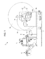
FIG. 1 is a side view of a printer provided with a paper feeding device according to an embodiment of the present invention; -
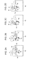
FIGS. 2A-2D are views of one side plate of the paper feeding device illustrated inFIG. 1 when seen from a back side, in which:FIG. 2A is a view when a near end sensor is brought closest to a rotating shaft set to a second notch;FIG. 2B is a view when the near end sensor is furthest away from the rotating shaft set to the second notch;FIG. 2C is a view when the near end sensor is furthest away from the rotating shaft set to a first notch; andFIG. 2D is a view when the near end sensor is brought closest to the rotating shaft set to the first notch; and -
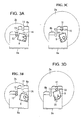
FIGS. 3A-3D are views of the one side plate of the paper feeding device illustrated inFIG. 1 andFigs. 2A and 2D when seen from a front side, in which:FIG. 3A is a view when a near end sensor is brought closest to a rotating shaft set to a second notch;FIG. 3B is a view when the near end sensor is furthest away from the rotating shaft set to the second notch;FIG. 3C is a view when the near end sensor is furthest away from the rotating shaft set to a first notch; andFIG. 3D is a view when the near end sensor is brought closest to the rotating shaft set to the first notch. - Hereinafter, an embodiment of a paper feeding device according to the present invention is described with reference to
FIGS. 1 to 3A-3D . -
FIG. 1 is a side view of a printer provided with the paper feeding device according to this embodiment.FIGS. 2A-2D are views of one side plate of the paper feeding device when seen from a back side.FIGS. 3A-3D are views of the one side plate of the paper feeding device illustrated inFIG. 1 when seen from a front side. - As illustrated in
FIG. 1 , a printer 1 includes a printing device 4 that prints various kinds of information on a thermal printing layer of a sheet of a paper roll (thermal paper, for example) 2a (2b) fed from apaper feeding device 3 in a conveying direction of the sheet of thepaper roll 2a (2b), a cutting device (paper cutting device) 5 that cuts the sheet of thepaper roll 2a (2b) printed by the printing device 4, and apaper discharging device 6 that takes out (discharges) the sheet of thepaper roll 2a (2b) cut by the cutting device 5 from a bezel (paper outlet) (not shown). - The printing device 4 is a so-called thermal printer, and has a thermal head for heating the thermal printing layer of the sheet of the
paper roll 2a (2b) and a platen roller (not shown) pressed to the thermal head. The printing device 4 performs printing while pinching the sheet of thepaper roll 2a (2b) fed from thepaper feeding device 3 between the thermal head and the platen roller, and conveys the same. - The cutting device 5 has, for example, a pair of disk-like rotating blades (not shown) for cutting the sheet of the
paper roll 2a (2b) taken out from the printing device 4 to a desired length, and conveys the cut sheet of thepaper roll 2a (2b) to thepaper discharging device 6. - Further, the
paper feeding device 3, the printing device 4, the cutting device 5, and thepaper discharging device 6 are combined through amain body frame 7. - As illustrated in
FIG. 1 , thepaper feeding device 3 according to this embodiment includes apaper holder 8 and anear end sensor 9. - The
paper holder 8 has abottom plate 8a having a substantially rectangular shape in plan view extending in the conveying direction and a width direction of the sheet of thepaper roll 2a (2b), and twoside plates 8b extending upward in a vertical direction from side edges of thebottom plate 8a. - On each
side plate 8b of thepaper holder 8 there are provided, for example, afirst notch 11 which is set to a center portion of thepaper roll 2a having 6 inches diameter and bearing-supports a rotatingshaft 10 rotating together with thepaper roll 2a, and, for example, asecond notch 13 which is set to a center portion of thepaper roll 2b having 4 inches diameter and bearing-supports a rotatingshaft 12 rotating together with thepaper roll 2b. Thefirst notch 11 and thesecond notch 13 are formed such that a front end (end portion on the printing device 4 side) 14 of an outer peripheral surface of the unused (new)paper roll 2a having 6 inches diameter when thepaper roll 2a is set to thefirst notch 11 through therotating shaft 10, and a front end (end portion on the printing device 4 side) 15 of an outer peripheral surface of the unused (new)paper roll 2b having 4 inches diameter when thepaper roll 2b is set to thesecond notch 13 through the rotatingshaft 12 are positioned in the same vertical plane. - Further,
grooves 16 are provided on oneside plate 8b of the paper holder 8 (near-side side plate 8b inFIG. 1 , in this embodiment). Thegrooves 16 guide twoprotrusions 9a protruding from a back surface of the near end sensor 9 (inner-side surface inFIG. 1 ) and serve as openings which are required for asensor portion 9b arranged on the back surface of thenear end sensor 9 to detect a remaining amount of thepaper roll 2a (2b). Thegrooves 16 are formed such that a distance between thesensor portion 9b of thenear end sensor 9 and a rotation center of therotating shaft 12 when thenear end sensor 9 is brought closest to the rotatingshaft 12 set to the second notch 13 (see,FIGS. 2A and3A ) and a distance between thesensor portion 9b of thenear end sensor 9 and a rotation center of therotating shaft 10 when thenear end sensor 9 is brought closest to the rotatingshaft 10 set to the first notch 11 (see,FIGS. 2D and3D ) are equal. Thegroove 16 is also formed such that a distance between thesensor portion 9b of thenear end sensor 9 and the rotation center of therotating shaft 12 when thenear end sensor 9 is furthest away from therotating shaft 12 set to the second notch 13 (see,FIGS. 2B and3B ) and a distance between thesensor portion 9b of thenear end sensor 9 and the rotation center of therotating shaft 10 when thenear end sensor 9 is furthest away from the rotatingshaft 10 set to the first notch 11 (see,FIGS. 2C and3C ) are equal. Further, thegrooves 16 allow thenear end sensor 9 to slide along the oneside plate 8b between a position illustrated inFIGS. 2A and3A and a position illustrated inFIGS. 2B and3B , and to slide along the oneside plate 8b between a position illustrated inFIGS. 2C and3C and a position illustrated inFIGS. 2D and3D . Moreover, thegrooves 16 are formed to allow thenear end sensor 9 to rotate along the oneside plate 8b between the position illustrated inFIGS. 2B and3B and the position illustrated inFIGS. 2C and3C . - In the
paper feeding device 3 according to this embodiment, thefirst notch 11 and thesecond notch 13 are provided on eachside plate 8b of thepaper holder 8, and hence any one of the twopaper rolls - Further, when the
paper roll 2a having 6 inches diameter or thepaper roll 2b having 4 inches diameter in the unused state is mounted to thefirst notch 11 or thesecond notch 13, thefirst notch 11 and thesecond notch 13 are formed such that the front ends 14, 15 of the outer peripheral surface of the paper rolls 2a, 2b are positioned in substantially the same vertical plane, whereby it is possible to stably feed a paper sheet to the printing device 4 in the case of using any one of the paper rolls 2a, 2b. - Moreover, in the
paper feeding device 3 according to this embodiment, thegrooves 16 are provided on the oneside plate 8b of thepaper holder 8. Accordingly, a user can set thenear end sensor 9 in a desired position easily and rapidly in accordance with the diameter of thepaper roll 2a (2b) selected appropriately as needed. - Note that, adjusting the position of the
near end sensor 9 can be performed by merely being slid or rotated along thegroove 16, and hence anyone can perform easily. - On the other hand, a manufacturer which manufactures and sells the paper feeding device does not need to prepare paper holders corresponding to respective paper rolls having the different diameters in the unused state, and hence the number of components can be reduced. Further, it is possible to reduce the manufacturing cost and to realize the simplification of parts control.
- The printer 1 provided with the
paper feeding device 3 according to the present invention includes thepaper feeding device 3 which can mount the paper rolls 2a, 2b having the different diameters in the unused (new) state freely according to the choice of a user, whereby it is possible to increase the convenience for a user. - Note that, the present invention is not limited to the embodiment as described above, and variation or modification can be effected appropriately as needed without departing from the technical idea of the present invention. For example, while in the above-mentioned embodiment, the
paper holder 8 which can hold thepaper roll 2a having 6 inches diameter or thepaper roll 2b having 4 inches diameter is described as a specific example, the present invention is not limited thereto. Thepaper holder 8 may hold a paper roll having 8 inches diameter or a paper roll having 4 inches diameter, the paper roll having 8 inches diameter or a paper roll having 6 inches diameter, or the paper roll having 8 inches diameter, the paper roll having 6 inches diameter, or the paper roll having 4 inches diameter, as further examples.
Claims (5)
- A paper feeding device (3) that feeds a sheet of a paper roll to a printing device (4), comprising:two side plates (8b) vertically arranged along both sides of the paper roll; anda plurality of notches (11, 13), which are capable of bearing-supporting paper rolls (2a, 2b) having different diameters in an unused state, formed in the side plates,wherein, when the notches are mounted with corresponding paper rolls in the unused state, end portions (14, 15) of outer peripheral surfaces of the paper rolls on a printing device side are arranged to be positioned in substantially the same vertical plane.
- A paper feeding device according to claim 1, wherein, on any one of the side plates (8b), a near end sensor (9) which detects a remaining amount of the paper roll is arranged, and grooves (16) which allow the near end sensor to slide in a radial direction of the paper rolls (2a, 2b) bearing-supported by the notches (11, 13) are provided.
- A paper feeding device according to claim 2, wherein the grooves (16) are formed such that distances between rotation centers of the paper rolls and a sensor portion (9b) of the near end sensor are the same when the near end sensor is brought closest to the rotation centers of the paper rolls, and distances between the rotation centers of the paper rolls and the sensor portion of the near end sensor are the same when the near end sensor is furthest away from the rotation centers of the paper rolls.
- A paper feeding device according to claim 2 or claim 3, wherein the grooves are connected through a groove portion which allows the near end sensor to rotate along the side plate.
- A printer comprising the paper feeding device according to any of the preceding claims.
Applications Claiming Priority (1)
| Application Number | Priority Date | Filing Date | Title |
|---|---|---|---|
| JP2007323597A JP2009143695A (en) | 2007-12-14 | 2007-12-14 | Paper feeder |
Publications (3)
| Publication Number | Publication Date |
|---|---|
| EP2070851A2 true EP2070851A2 (en) | 2009-06-17 |
| EP2070851A3 EP2070851A3 (en) | 2010-11-24 |
| EP2070851B1 EP2070851B1 (en) | 2013-01-16 |
Family
ID=40404945
Family Applications (1)
| Application Number | Title | Priority Date | Filing Date |
|---|---|---|---|
| EP08170297A Ceased EP2070851B1 (en) | 2007-12-14 | 2008-11-28 | Paper feeding device |
Country Status (4)
| Country | Link |
|---|---|
| US (1) | US7828239B2 (en) |
| EP (1) | EP2070851B1 (en) |
| JP (1) | JP2009143695A (en) |
| KR (1) | KR101483797B1 (en) |
Cited By (2)
| Publication number | Priority date | Publication date | Assignee | Title |
|---|---|---|---|---|
| DE202010008510U1 (en) | 2010-09-10 | 2010-11-18 | Hostert Pro Gmbh | Freestanding feeder for printing material rolls |
| EP2093172B1 (en) * | 2008-02-22 | 2015-10-14 | Seiko Instruments Inc. | Paper Feeding Device |
Families Citing this family (4)
| Publication number | Priority date | Publication date | Assignee | Title |
|---|---|---|---|---|
| JP6322381B2 (en) * | 2013-10-17 | 2018-05-09 | 富士通コンポーネント株式会社 | Printer device |
| DE102019001174A1 (en) * | 2019-02-18 | 2020-08-20 | Giesecke+Devrient Currency Technology Gmbh | Device for packaging sheet material |
| US11071416B2 (en) * | 2019-03-25 | 2021-07-27 | Hunter James Hollister | Product monitoring device |
| CN112706464B (en) * | 2019-10-26 | 2023-01-20 | 江苏亚振电力有限公司 | Automatic insulating crepe paper pipe processingequipment of material loading processing |
Citations (1)
| Publication number | Priority date | Publication date | Assignee | Title |
|---|---|---|---|---|
| JPH05345429A (en) | 1992-06-16 | 1993-12-27 | Nec Data Terminal Ltd | Thermal printer equipment |
Family Cites Families (8)
| Publication number | Priority date | Publication date | Assignee | Title |
|---|---|---|---|---|
| US4277034A (en) * | 1979-05-21 | 1981-07-07 | Centronics Data Computer Corp. | Paper roll holder with dancer bar for use with printers and the like |
| US5302037A (en) * | 1992-04-10 | 1994-04-12 | Hecon Corporation | Web handling and feeding system for printers |
| US5374007A (en) * | 1993-01-22 | 1994-12-20 | Ncr Corporation | Ribbon supply apparatus |
| JPH07101601A (en) * | 1993-10-04 | 1995-04-18 | Star Micronics Co Ltd | Roll paper holder |
| US5725321A (en) * | 1995-12-07 | 1998-03-10 | Interbold | Journal printer paper feed fault detection system for automated teller machine |
| JP2003267596A (en) | 2002-03-12 | 2003-09-25 | Fuji Photo Film Co Ltd | Recording paper roll holder device |
| TWI283650B (en) * | 2004-04-23 | 2007-07-11 | Bobst Sa | Module for supporting and driving a wound foil matter for a machine processing it |
| NL1027496C2 (en) * | 2004-11-12 | 2006-05-15 | Oce Tech Bv | Printer, supply unit for this printer and device for inclusion in this supply unit. |
-
2007
- 2007-12-14 JP JP2007323597A patent/JP2009143695A/en not_active Withdrawn
-
2008
- 2008-11-28 EP EP08170297A patent/EP2070851B1/en not_active Ceased
- 2008-12-04 US US12/315,637 patent/US7828239B2/en not_active Expired - Fee Related
- 2008-12-11 KR KR20080125875A patent/KR101483797B1/en not_active Expired - Fee Related
Patent Citations (1)
| Publication number | Priority date | Publication date | Assignee | Title |
|---|---|---|---|---|
| JPH05345429A (en) | 1992-06-16 | 1993-12-27 | Nec Data Terminal Ltd | Thermal printer equipment |
Cited By (3)
| Publication number | Priority date | Publication date | Assignee | Title |
|---|---|---|---|---|
| EP2093172B1 (en) * | 2008-02-22 | 2015-10-14 | Seiko Instruments Inc. | Paper Feeding Device |
| DE202010008510U1 (en) | 2010-09-10 | 2010-11-18 | Hostert Pro Gmbh | Freestanding feeder for printing material rolls |
| EP2428478A2 (en) | 2010-09-10 | 2012-03-14 | Hostert Pro GmbH | Free-standing supply device for rolls of print material |
Also Published As
| Publication number | Publication date |
|---|---|
| US7828239B2 (en) | 2010-11-09 |
| US20090152793A1 (en) | 2009-06-18 |
| EP2070851A3 (en) | 2010-11-24 |
| EP2070851B1 (en) | 2013-01-16 |
| KR20090064318A (en) | 2009-06-18 |
| JP2009143695A (en) | 2009-07-02 |
| KR101483797B1 (en) | 2015-01-16 |
Similar Documents
| Publication | Publication Date | Title |
|---|---|---|
| EP2093172B1 (en) | Paper Feeding Device | |
| EP2070851B1 (en) | Paper feeding device | |
| EP3619010B1 (en) | Stand-alone cutting apparatus | |
| CN105050822B (en) | printer | |
| EP2258555A1 (en) | Handheld type print label producing apparatus | |
| JP2009090491A (en) | Thermal printer unit and printing device | |
| JP2012152951A (en) | Printing device | |
| JP2006021497A (en) | Printing device | |
| CN1931673B (en) | Thermal activation device, printing device and printer | |
| JP3758118B2 (en) | Roll paper holding device | |
| JP6893612B2 (en) | Plate making equipment, stencil printing press and multiple types of master rolls of different sizes | |
| US20120031944A1 (en) | Conveying device, printer, and abutting member | |
| JP6458293B2 (en) | Master roll and stencil printing machine | |
| JP4770579B2 (en) | Printing device | |
| KR200401364Y1 (en) | Device for feeding paper of printer | |
| JP2004331351A (en) | Paper feeding device | |
| CN215944062U (en) | Width adjustable label printer | |
| JP4529741B2 (en) | Tape cassette | |
| JP5834552B2 (en) | Printer | |
| JP2012035637A (en) | Tape cassette | |
| JP4655148B2 (en) | Paper width detecting device and image forming apparatus | |
| JP3842523B2 (en) | Paper cutting device | |
| JP4725566B2 (en) | Roll sheet holder | |
| JP2013052606A (en) | Printer | |
| JP5686163B2 (en) | Tape cassette |
Legal Events
| Date | Code | Title | Description |
|---|---|---|---|
| PUAI | Public reference made under article 153(3) epc to a published international application that has entered the european phase |
Free format text: ORIGINAL CODE: 0009012 |
|
| AK | Designated contracting states |
Kind code of ref document: A2 Designated state(s): AT BE BG CH CY CZ DE DK EE ES FI FR GB GR HR HU IE IS IT LI LT LU LV MC MT NL NO PL PT RO SE SI SK TR |
|
| AX | Request for extension of the european patent |
Extension state: AL BA MK RS |
|
| PUAL | Search report despatched |
Free format text: ORIGINAL CODE: 0009013 |
|
| AK | Designated contracting states |
Kind code of ref document: A3 Designated state(s): AT BE BG CH CY CZ DE DK EE ES FI FR GB GR HR HU IE IS IT LI LT LU LV MC MT NL NO PL PT RO SE SI SK TR |
|
| AX | Request for extension of the european patent |
Extension state: AL BA MK RS |
|
| 17P | Request for examination filed |
Effective date: 20110412 |
|
| AKX | Designation fees paid |
Designated state(s): DE FR IT |
|
| REG | Reference to a national code |
Ref country code: DE Ref legal event code: R079 Ref document number: 602008021678 Country of ref document: DE Free format text: PREVIOUS MAIN CLASS: B65H0016000000 Ipc: B65H0016020000 |
|
| RIC1 | Information provided on ipc code assigned before grant |
Ipc: B65H 16/06 20060101ALI20120105BHEP Ipc: B65H 16/02 20060101AFI20120105BHEP |
|
| GRAP | Despatch of communication of intention to grant a patent |
Free format text: ORIGINAL CODE: EPIDOSNIGR1 |
|
| RIN1 | Information on inventor provided before grant (corrected) |
Inventor name: ITO, AKIHIKO |
|
| GRAS | Grant fee paid |
Free format text: ORIGINAL CODE: EPIDOSNIGR3 |
|
| GRAA | (expected) grant |
Free format text: ORIGINAL CODE: 0009210 |
|
| AK | Designated contracting states |
Kind code of ref document: B1 Designated state(s): DE FR IT |
|
| REG | Reference to a national code |
Ref country code: DE Ref legal event code: R096 Ref document number: 602008021678 Country of ref document: DE Effective date: 20130314 |
|
| PLBE | No opposition filed within time limit |
Free format text: ORIGINAL CODE: 0009261 |
|
| STAA | Information on the status of an ep patent application or granted ep patent |
Free format text: STATUS: NO OPPOSITION FILED WITHIN TIME LIMIT |
|
| 26N | No opposition filed |
Effective date: 20131017 |
|
| REG | Reference to a national code |
Ref country code: DE Ref legal event code: R097 Ref document number: 602008021678 Country of ref document: DE Effective date: 20131017 |
|
| REG | Reference to a national code |
Ref country code: FR Ref legal event code: PLFP Year of fee payment: 8 |
|
| REG | Reference to a national code |
Ref country code: FR Ref legal event code: PLFP Year of fee payment: 9 |
|
| REG | Reference to a national code |
Ref country code: FR Ref legal event code: PLFP Year of fee payment: 10 |
|
| REG | Reference to a national code |
Ref country code: FR Ref legal event code: PLFP Year of fee payment: 11 |
|
| PGFP | Annual fee paid to national office [announced via postgrant information from national office to epo] |
Ref country code: DE Payment date: 20201118 Year of fee payment: 13 Ref country code: FR Payment date: 20201013 Year of fee payment: 13 Ref country code: IT Payment date: 20201013 Year of fee payment: 13 |
|
| REG | Reference to a national code |
Ref country code: DE Ref legal event code: R119 Ref document number: 602008021678 Country of ref document: DE |
|
| PG25 | Lapsed in a contracting state [announced via postgrant information from national office to epo] |
Ref country code: DE Free format text: LAPSE BECAUSE OF NON-PAYMENT OF DUE FEES Effective date: 20220601 |
|
| PG25 | Lapsed in a contracting state [announced via postgrant information from national office to epo] |
Ref country code: FR Free format text: LAPSE BECAUSE OF NON-PAYMENT OF DUE FEES Effective date: 20211130 |
|
| PG25 | Lapsed in a contracting state [announced via postgrant information from national office to epo] |
Ref country code: IT Free format text: LAPSE BECAUSE OF NON-PAYMENT OF DUE FEES Effective date: 20211128 |