EP2070778A1 - Airbag apparatus - Google Patents
Airbag apparatus Download PDFInfo
- Publication number
- EP2070778A1 EP2070778A1 EP08169591A EP08169591A EP2070778A1 EP 2070778 A1 EP2070778 A1 EP 2070778A1 EP 08169591 A EP08169591 A EP 08169591A EP 08169591 A EP08169591 A EP 08169591A EP 2070778 A1 EP2070778 A1 EP 2070778A1
- Authority
- EP
- European Patent Office
- Prior art keywords
- airbag
- vehicle
- main expanding
- expanding portion
- main
- Prior art date
- Legal status (The legal status is an assumption and is not a legal conclusion. Google has not performed a legal analysis and makes no representation as to the accuracy of the status listed.)
- Withdrawn
Links
- 238000001514 detection method Methods 0.000 claims abstract description 9
- 230000003213 activating effect Effects 0.000 claims abstract description 3
- 238000007664 blowing Methods 0.000 claims abstract description 3
- 230000002265 prevention Effects 0.000 description 17
- 238000010276 construction Methods 0.000 description 13
- 230000008878 coupling Effects 0.000 description 10
- 238000010168 coupling process Methods 0.000 description 10
- 238000005859 coupling reaction Methods 0.000 description 10
- 238000000034 method Methods 0.000 description 2
- 238000012986 modification Methods 0.000 description 2
- 230000004048 modification Effects 0.000 description 2
- 239000004744 fabric Substances 0.000 description 1
- 239000011521 glass Substances 0.000 description 1
- 238000000465 moulding Methods 0.000 description 1
- 230000002093 peripheral effect Effects 0.000 description 1
- 238000004393 prognosis Methods 0.000 description 1
Images








Classifications
-
- B—PERFORMING OPERATIONS; TRANSPORTING
- B60—VEHICLES IN GENERAL
- B60R—VEHICLES, VEHICLE FITTINGS, OR VEHICLE PARTS, NOT OTHERWISE PROVIDED FOR
- B60R21/00—Arrangements or fittings on vehicles for protecting or preventing injuries to occupants or pedestrians in case of accidents or other traffic risks
- B60R21/34—Protecting non-occupants of a vehicle, e.g. pedestrians
- B60R21/36—Protecting non-occupants of a vehicle, e.g. pedestrians using airbags
Definitions
- the present invention belongs to a technical field of an airbag apparatus for absorbing an impact applied to an object of a collision or a vehicle, upon expanding and developing to an outside of the vehicle by means of a gas from an inflator or the like, in an emergency such as a case when the vehicle collides with the object of the collision, or the like.
- an airbag apparatus that absorbs an impact generated by a re-collision between a pedestrian or the like, and a vehicle, by means of causing the airbag to expand to a rear side of a hood and an outside of pillar portions of the vehicle at a time of collision between the vehicle and the pedestrian or the like, is known.
- an airbag apparatus in which an airbag apparatus is mounted in an engine hood, and an airbag is extended along a front shield glass and front pillars at a time of expansion and development of the airbag, is disclosed (refer to JP-A-2007-112183 (Patent Document 1)).
- an airbag apparatus in which an airbag module extending in a left-and-right direction of a vehicle is arranged between a rear edge of a hood and a front edge of a cowl top, is supported by means of a damper housing having high rigidity without applying an influence to the arrangement of an air-suction inlet, a wiper, and so forth is disclosed (refer to JP-A-2006-62488 (Patent Document 2)).
- the present invention is made in consideration of the above-described situation, and the object of the present invention is to provide an airbag apparatus that is capable of rapidly developing, and is small in size and light in weight.
- the invention as claimed in Claim 1 is characterized in that in an airbag apparatus including an airbag, a gas-generator for blowing out a gas into an inside of the airbag, a detection device for detecting a collision, and a control device for activating the gas-generator by means of a signal from the detection device, and expanding the airbag on an outside of a vehicle, the airbag is formed in an approximately U-shaped manner including a first main expanding portion, and a second main expanding portion respectively extending from both ends of the first main expanding portion, and is housed in an approximately U-shaped state, and is developed in an approximately U-shaped manner.
- the invention as claimed in Claim 2 is characterized in that the airbag is configured to fix only the second main expanding portions to a vehicle body side.
- the invention as claimed in Claim 3 is characterized in that the first main expanding portion is disposed at a front side below the windshield on the outside of the vehicle, and the second main expanding portions are disposed along front pillars, respectively, on the outside of the vehicle.
- the invention as claimed in Claim 4 is characterized in that the airbag includes a third main expanding portion that couples end portions of the respective second main expanding portions and faces the first main expanding portion, and that is disposed on the windshield side of a roof on the outside of the vehicle, and the airbag is formed to have an approximately closed rectangle shape, and is housed in a state of the approximately closed rectangle shape, and is developed in the approximately closed rectangle manner.
- the invention as claimed in Claim 5 is characterized in that the first main expanding portion is disposed on a windshield side of a roof on the outside of the vehicle, and the second main expanding portions are disposed along front pillars, respectively, on the outside of the vehicle.
- the airbag is formed in an approximately U-shaped manner including a first main expanding portion and second main expanding portions respectively extending from both ends of the first main expanding portion, and is housed in an approximately U-shaped state, and is developed in an approximately U-shaped manner, a distance from the housed position to the developing position is small and thereby the airbag can be rapidly developed.
- the airbag is configured to fix only the second main expanding portion to the vehicle body side, a case having rigidity, for the first main expanding portion is not necessary, and a size and a weight of the airbag apparatus can be lightened as a whole.
- the first main expanding portion is disposed at a front side below the windshield on the outside of the vehicle, and the second main expanding portions are disposed along the respective front pillars on the outside of the vehicle, the impact generated by a re-collision between a pedestrian or the like and a vehicle is absorbed.
- the airbag is provided with a third main expanding portion that couples end portions of the respective second main expanding portions and faces the first main expanding portion, and is disposed on the windshield side of the roof on the outside of the vehicle, and is formed to have an approximately closed rectangle shape, and is housed in a state of the approximately closed rectangle shape, and is developed in the approximately closed rectangle manner, the impact generated by the re-collision between the pedestrian or the like and the vehicle can be absorbed.
- the first main expanding portion is disposed on the windshield side of the roof on the outside of the vehicle, and the second main expanding portions are disposed along the respective front pillars on the outside of the vehicle, the impact generated by the re-collision between the pedestrian or the like and the vehicle can be absorbed.
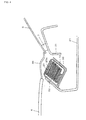
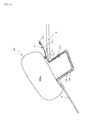
- Fig. 1 illustrates an airbag 20 according to the present invention.
- the airbag 20 according to the present invention is formed of a base cloth whose outer periphery is stitched, and is composed of a main expanding portion 20a formed of an approximately U-shape and including a first main expanding portion 20a 1 at a center and second main expanding portions 20a 2 respectively extending from both ends of the first main expanding portion 20a 1 , a pipe-connecting portion 20b, and a latching portion 20c.
- the main expanding portion 20a has an approximately elliptic shape, and is a portion that absorbs an impact generated by a collision between an object of the collision such as a pedestrian or the like, and a vehicle at a time of an expanding operation thereof.
- the pipe-connecting portion 20b is protruded from the main expanding portion 20a, and is a portion where a pipe 16 is inserted and swaged therewith.
- the latching portion 20c is provided upon protruded in an approximately perpendicular direction to a longitudinal direction of the second main expanding portion 20a 2 and is a portion for latching the airbag 20 to a vehicle body.
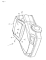
- Fig. 2 is a perspective view illustrating a vehicle on which an airbag apparatus according to the first embodiment is mounted
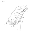
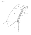
- Fig. 3 is a perspective view illustrating the vicinity of a front pillar of the vehicle according to the first embodiment
- Fig. 4 is a cross-sectional view taken along a line a-a in Fig. 3
- Fig. 5 is a cross-sectional view taken along a line b-b in Fig. 3
- Fig. 6 is a cross-sectional view taken along a line c-c in Fig. 3
- Fig. 7 is a cross-sectional view taken along a line d-d in Fig. 3
- Fig. 8 is a cross-sectional view taken along a line e-e in Fig. 3 .
- a numeral 1 denotes the vehicle
- a numeral 2 denotes the front pillar
- a numeral 3 denotes a fender
- a numeral 4 denotes a hood
- a numeral 5 denotes a roof
- a numeral 6 denotes a windshield
- a numeral 7 denotes a seal
- a numeral 8 denotes a side-outer panel
- a numeral 9 denotes a concave portion
- a numeral 10 denotes the airbag apparatus
- a numeral 11 denotes a cover
- a numeral 12 denotes a bag case
- a numeral 13 denotes an anchor
- a numeral 15 denotes a gas-generator
- a numeral 16 denotes a pipe
- a numeral 17 denotes a cover-splash prevention member
- a numeral 18 denotes a retainer
- a numeral 19 denotes a fixing
- the vehicle 1 is provided with the front pillars 2 that couple a not-illustrated member or an engine room frame with the roof 5. Further, the vehicle 1 is provided with the windshield 6 surrounded by the hood 4, the roof 5, and the front pillars 2, and attached thereto via the seal 7.
- Fig. 4 illustrates a housing state of the first main expanding portion 20a 1 of the airbag 20.
- the cowl top 30 is disposed in a clearance between a front side below the windshield 6 and a rear side of the hood 4.
- the first main expanding portion 20a 1 of the airbag 20 is held in the dashboard 31 underneath the cowl top 30 by means of the clip 32 or the like in a state of being housed in the bag case 12.
- the guide plate 33 for guiding a developing direction of the first main expanding portion 20a 1 of the airbag 20 at a time when the airbag 20 is expanded is provided.
- Fig. 5 also illustrates the housing state of the second main expanding portion 20a 2 of the airbag 20.
- the airbag apparatus 10 is housed on a windshield 6 side of the front pillar 2 and the fender 3.
- the front pillar 2 is provided with a first surface 2a facing an outside of the vehicle 1 and a second surface 2b facing the windshield 6 side, and the second main expanding portion 20a 2 of the airbag 20 is housed in the cover 11 in a state of being folded back and housed in the bag case 12 on the second surface 2b side.
- the bag case 12 is formed to have a U-shape in conformity to a U-shape of the airbag 20.
- the bag case 12 is not always necessary to be formed to have the U-shape.
- the cover 11 is formed of a member having an approximately L-shape in cross-section provided with an upper cover 11a and a side cover 11b on the windshield 6 side, and is disposed in a manner so as to hide the second main expanding portion 20a 2 of the airbag 20, which is folded back on the second surface 2b side of the front pillar 2.
- the second main expanding portion 20a 2 of the folded-back airbag 20 may be directly housed in the cover 11 without being housed in the bag case 12.
- the cover-splash prevention member 17 such as a strap or the like is inserted into a folded-back portion 11c of the upper cover 11a.
- a seal 11d is attached, and is configured to cover a clearance between the front pillar 2 and the cover 11 and to increase a design performance and a water-tightness.
- a gas-generator 15 that generates a gas for expanding the airbag 20 and the pipe 16 for supplying the gas generated by the gas-generator 15 into the airbag 20, and so forth are housed.
- the gas generator 15 is disposed in the concave portion 9 in a state of being covered by the retainer 18, and is fixed to the roof 5 and the side-outer panel 8 with a fixing device 19 such as a bolt 19a and a nut 19b, or the like.
- the concave portion 9 is configured such that an opening portion is obstructed by means of a roof molding 5a.
- the pipe 16 is disposed in the concave portion 9 similar to the case of the gas-generator 15, and is coupled with the airbag 20 by means of the coupling device 21, such as a clamp band or the like.
- the coupling device 21 is not always necessary to be disposed in the concave portion 9.
- a harness 30 which is coupled with a not-illustrated power source, a control device, and so forth, is coupled, and is disposed in the concave portion 9 along a vehicle-rear side.
- Fig. 9 is a view illustrating an attaching method for attaching a gas-generator 15 according to the present invention.
- the retainer 18 is provided with a main body portion 18a for covering and holding the gas-generator 15, an attaching portion 18b for fixing the retainer 15 to the vehicle body in the concave portion 9, and an attaching hole 18c.
- the gas-generator 15 in a state of being covered with the retainer 18 is inserted into the concave portion 9 while sliding therewith.
- a hole 58 is formed at a coupling portion in the concave portion 9 where the roof 5 and the side-outer panel 8 are coupled, and on an opposite side of the concave portion 9 of the hole 58, a nut 19b is previously fixed.
- the attaching hole 18c of the inserted retainer 18 is disposed in a manner so as to overlap with the hole 58 and fixed by means of the bolt 19a.
- FIG. 10 is a view illustrating an operation of the airbag apparatus 10 according to the present embodiment.
- the airbag apparatus 10 in a housed-state illustrated in Fig. 3 through Fig. 5 is operated by means of the control device or the like on the basis of a detection signal in a case that the vehicle 1 collides with a not-illustrated object of the collision, and an impact force generated in the vehicle 1 is detected by means of a not-illustrated detection device or the like, or in a case that the vehicle 1 collides with a not-illustrated object of the collision, and a prognosis of the collision is detected by means of a detection device or the like.
- Fig. 10(a) illustrates an initial stage of the expanding operation in which the airbag apparatus 10 starts the operation, and the gas flows into an inside of the airbag 20 from the gas-generator 15 housed in the concave portion 9 through the pipe 16, and the airbag 20 starts to be expanded.
- the airbag 20 starts to be expanded from the roof 5 side, and the cover 11 and the cowl top 30 illustrated in Fig. 3 through Fig. 5 are developed by means of an expanding pressure of the airbag 20.
- Fig. 10(b) illustrates an intermediate stage of the expanding operation in which the gas flows into the inside of the airbag 20 from the gas-generator 15 through the pipe 16, and the airbag 20 continues the expanding operation.
- the intermediate stage of the expanding operation an entire airbag 20 is completely exposed to the outside from the folded-back state.
- Fig. 10(c) illustrates a completion stage of the expanding operation in which the expanding operation of the airbag 20 is completed. In the completion stage of the expanding operation, the airbag 20 is completely expanded. A state of the airbag apparatus 10 in the completion stage of the expanding operation will be explained below.
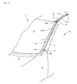
- Fig. 11 is a perspective view illustrating the vehicle in the completion stage of the expanding operation of the airbag
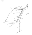
- Fig. 12 is a perspective view illustrating the vicinity of the front pillar 2 in the completion stage of the expanding operation of the airbag
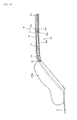
- Fig. 13 is a cross-sectional view taken along a line f-f in Fig. 12
- Fig. 14 is a cross-sectional view taken along a line g-g in Fig. 12
- Fig. 15 is a cross-sectional view taken along a line h-h in Fig. 12
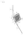
- Fig. 16 is a view similar to Fig. 12 where the airbag 20 is omitted.
- the first main expanding portion 20a 1 of the airbag 20 is developed in a direction following the cowl top 30 disposed in a clearance between a rear side of the hood 4 and the front side below the windshield 6, and the second main expanding portions 20a 2 of the airbag 20 is developed in a direction following the front pillars 2, respectively, above a part of the fender 3 and the hood 4, and at the front side of the front pillar 2.
- the first main expanding portion 20a 1 of the airbag 20 expands and opens the cowl top 30, and is developed toward a space at the rear side of the hood 4 and the front side below the windshield 6.
- the first main expanding portion 20a 1 itself is not fixed to any place, and is fixed via the second main expanding portions 20a 2 by means of the latching portion 20c.
- the first main expanding portion 20a 1 itself is not fixed to any place, a case having rigidity is not necessary, and a size and a weight of the airbag apparatus 10 can be vastly lightened.
- the cover 11 is spaced apart from the front pillar 2 and the windshield 6, and the second main expanding portions 20a 2 of the airbag 20 is expanded toward a front side of the front pillar 2 having high possibility to be collided with the object of a collision, such as a pedestrian or the like.
- the cover-splash prevention member 17 may be divided into a cover-splash prevention member 17a for coupling the gas-generator 15 and the like with the cover 11, and a cover-splash prevention member 17b for coupling the anchor 13 with the cover 11.
- the harness 40 to be coupled with the gas-generator 15 may have a structure that is folded back from a rear side and that is caused to follow the front side of the vehicle in the concave portion 9.
- the present invention is not limited thereto and various modifications may be applicable.
- Fig. 18 is a perspective view illustrating the vicinity of the front pillar of the vehicle in which an airbag apparatus according to the second embodiment is mounted
- Fig. 19 is a cross-sectional view taken along a line i-i in Fig. 18 .
- a numeral 5a denotes a housing portion
- a numeral 41 denotes a second cover
- a numeral 42 denotes a clip
- Fig. 19 illustrates a housing state of the first main expanding portion 20a 1 of the airbag 20.
- a concave shaped housing portion 5a is formed in the roof 5. It is preferable if the housing portion 5a is located along an upper edge of the windshield 6.
- the first main expanding portion 20a 1 of the airbag 20 is held by means of the housing portion 5a with the clip 42 or the like in a state of being housed in the bag case 12.
- a second cover 41 is provided above the bag case 12 in a manner so as to cover the housing portion 5a.
- the second cover 41 is provided with an upper cover 41a and a folded-back portion 41b, and is disposed in a manner so as to hide the first main expanding portion 20a 1 of the airbag 20.
- the first main expanding portion 20a 1 of the folded-back airbag 20 may be directly housed in the housing portion 5a without being housed in the bag case 12.
- a second cover-splash prevention member 47 such as a strap or the like is inserted into the folded-back portion 41b of the upper cover 41a.
- seals 41c and 41d are attached, and cover a clearance between the roof 5 and the upper cover 41a. This increases the design performance or the water-tightness in the housing portion 5a.
- the airbag 20 is formed to have a reversed U-shape.
- the bag case 12 is also formed to have the reversed U-shape.
- the bag case 12 is not always necessary to be formed to have the reversed U-shape.
- Fig. 20 is a perspective view illustrating the vehicle in the completion stage of the expanding operation of the airbag
- Fig. 21 is a cross-sectional view taken along a line j-j in Fig. 20 .
- the first main expanding portion 20a 1 of the airbag 20 is developed in a direction following the housing portion 5a
- the second main expanding portion 20a 2 of the airbag 20 is developed in a direction following the front pillar 2 above a part of the fender 3 and the hood 4, and in front of the front pillar 2.
- the first main expanding portion 20a 1 of the airbag 20 expands and opens the second cover 41 and is developed toward a space above the housing portion 5a and a boundary between the windshield 6 and the roof 5.
- the first main expanding portion 20a 1 itself is not fixed to any place and is fixed by means of the latching portion 20c illustrated in Fig. 18 via the second main expanding portion 20a 2 .
- the first main expanding portion 20a 1 itself is not fixed to any place, the case having rigidity is not necessary, and a size and a weight of the airbag apparatus 10 can be vastly lightened.
- the second cover 41 since the second cover 41 is latched to the vehicle body side by means of the second cover-splash prevention member 47 via the gas-generator 15 or the like, there is no possibility for the second cover 41 to be splashed from the vehicle 1. End portions of the second cover-splash prevention member 47 are respectively latched to the gas-generator 15 or a member for fixing the gas-generator 15 to the vehicle body.
- the second cover-splash prevention member 47 may be divided into two second cover-splash prevention members 47 that respectively couple the left and right gas-generators 15 or the like, with the second cover 41.
- the cover 11 is spaced apart from the front pillar 2 and the windshield 6, and the second main expanding portion 20a 2 of the airbag 20 are expanded toward a front side of the front pillar 2 having a high possibility to collide with the object of the collision, such as the pedestrian or the like.
- the cover 11 since the cover 11 is latched to the vehicle body side by means of the cover-splash prevention member 17 via the anchor 13, the gas-generator 15, and so forth, there is no possibility that the cover 11 is splashed from the vehicle 1.
- the one end 17a of the cover-splash prevention member 17 is latched to the gas-generator 15 or a member for fixing the gas-generator 15 to the vehicle body, and the other end 17b is latched to the vehicle body side, such as a root portion of the front pillar 2, a member, or the like by means of the anchor 13 or the like.
- the cover-splash prevention member 17 may be divided into a cover-splash prevention member 17a for coupling the gas-generator 15 and the like with the cover 11, and a cover-splash prevention member 17b for coupling the anchor 13 with the cover 11.
- the harness 40 which is coupled with the gas-generator 15, may have a structure that is folded back from a rear side and follows to a front side of the vehicle in the concave portion 9.
- the present invention is not limited thereto and various modifications may be applicable.
- Fig. 22 is a perspective view illustrating the vehicle in the completion stage of the expanding operation of the airbag according to a third embodiment.
- the third embodiment is constructed in such a way that the airbag 20 is formed to have a closed rectangle shape by means of providing a third main expanding portion 20a 3 connecting both ends of the U-shaped airbag 20 that is used in the first embodiment.
- the construction of the first main expanding portion 20a 1 when it is housed is similar to the construction in Fig. 3 and Fig. 4 by which the first embodiment is explained
- the construction of the second main expanding portion 20a 2 when it is housed is similar to that in Fig. 3 and Fig. 5
- the construction of the third main expanding portion 20a 3 when it is housed is similar to that in Fig. 18 and Fig. 19 , by which the state when the first main expanding portion 20a 1 in the second embodiment is housed is explained, the explanation is omitted.
- the construction of the first main expanding portion 20a 1 when the expanding operation thereof is completed is similar to the construction in Fig. 11 , Fig. 12 , and Fig. 13 in which the first embodiment is explained
- the construction of the second main expanding portion 20a 2 when the expanding operation thereof is completed is similar to the construction in Fig. 11 , Fig. 12 and Fig. 14
- the construction of the third main expanding portion 20a 3 when the expanding operation thereof is completed is similar to the construction in Fig. 20 and Fig. 21 by which the state when the first main expanding portion 20a 1 in the second embodiment is completed is explained, the explanation is omitted.
- the first main expanding portion 20a 1 and the third main expanding portion 20a 3 are not fixed to any place, a case having rigidity is not necessary, and a size and a weight of the airbag apparatus 10 can be vastly lightened.
- the airbag 20 is formed to have an approximately U-shape, which is provided with the first main expanding portion 20a 1 and the second main expanding portions 20a 2 respectively extending from both ends of the first main expanding portion 20a 1 , and is housed in an approximately U-shaped state, and is developed in an approximately U-shaped manner, a distance of the airbag 20 from a housed position to a developed position is small, and thereby the airbag 20 can be rapidly developed.
- the airbag 20 is configured to fix only the second main expanding portion 20a 2 to the vehicle body side, a case having rigidity, for the first main expanding portion 20a 1 is not necessary, and a size and a weight of the airbag apparatus 10 can be lightened as a whole.
- first main expanding portion 20a 1 is disposed at a front side below the windshield 6 on an outside of the vehicle
- second main expanding portion 20a 2 is disposed along the front pillar 2 on the outside of the vehicle
- the airbag is formed to have an approximately U-shape including the first main expanding portion and the second main expanding portions respectively extending from both ends of the first main expanding portion, and is housed in a state of the approximately U-shape, and is developed in the approximately U-shape manner, a distance from the housed position to the developing position is small and thereby the airbag can be rapidly expanded.
- the airbag is configured to fix only the second main expanding portion to the vehicle body side, a case having rigidity, for the first main expanding portion is not necessary, and a size and a weight of the airbag apparatus can be lightened as a whole.
- the first main expanding portion is disposed at a front side below the windshield on the outside of the vehicle, and the second main expanding portion is disposed along the front pillar on the outside of the vehicle, the impact generated by a re-collision between a pedestrian or the like, and a vehicle is absorbed.
- the airbag is provided with a third main expanding portion that couples end portions of the respective second main expanding portions, and faces the first main expanding portion, and is disposed on the windshield side of the roof on the outside of the vehicle, and is formed to have an approximately closed rectangle shape, and is housed in a state of the approximately closed rectangle shape, and is developed in the approximately closed rectangle manner, the impact generated by the re-collision between the pedestrian or the like and the vehicle can be absorbed.
- the third main expanding portion is disposed on the windshield side of the roof on the outside of the vehicle, and the second main expanding portion is disposed along the front pillar on the outside of the vehicle, the impact generated by the re-collision between the pedestrian or the like and the vehicle can be absorbed.
Landscapes
- Engineering & Computer Science (AREA)
- Mechanical Engineering (AREA)
- Body Structure For Vehicles (AREA)
Abstract
Description
- The present invention belongs to a technical field of an airbag apparatus for absorbing an impact applied to an object of a collision or a vehicle, upon expanding and developing to an outside of the vehicle by means of a gas from an inflator or the like, in an emergency such as a case when the vehicle collides with the object of the collision, or the like.
- Hitherto, an airbag apparatus that absorbs an impact generated by a re-collision between a pedestrian or the like, and a vehicle, by means of causing the airbag to expand to a rear side of a hood and an outside of pillar portions of the vehicle at a time of collision between the vehicle and the pedestrian or the like, is known.
- For example, an airbag apparatus in which an airbag apparatus is mounted in an engine hood, and an airbag is extended along a front shield glass and front pillars at a time of expansion and development of the airbag, is disclosed (refer to
JP-A-2007-112183 - Further, an airbag apparatus, in which an airbag module extending in a left-and-right direction of a vehicle is arranged between a rear edge of a hood and a front edge of a cowl top, is supported by means of a damper housing having high rigidity without applying an influence to the arrangement of an air-suction inlet, a wiper, and so forth is disclosed (refer to
JP-A-2006-62488 - However, in the airbag apparatus described in the
Patent Document 1, since the airbag expanding in a manner so as to cover the front pillar is mounted in the engine hood, a time required for the airbag to be developed up to an upper part of the front pillar is long.
Furthermore, in the airbag apparatus described in thePatent Document 2, since the airbag module itself is supported by means of the damper housing, a sufficient strength is required to a case of the airbag so that damage is not applied to the peripheral parts when developed, resulting in problems that the weight becomes high, and the size becomes large. - The present invention is made in consideration of the above-described situation, and the object of the present invention is to provide an airbag apparatus that is capable of rapidly developing, and is small in size and light in weight.
- In order to solve the above-described problems, the invention as claimed in
Claim 1 is characterized in that in an airbag apparatus including an airbag, a gas-generator for blowing out a gas into an inside of the airbag, a detection device for detecting a collision, and a control device for activating the gas-generator by means of a signal from the detection device, and expanding the airbag on an outside of a vehicle, the airbag is formed in an approximately U-shaped manner including a first main expanding portion, and a second main expanding portion respectively extending from both ends of the first main expanding portion, and is housed in an approximately U-shaped state, and is developed in an approximately U-shaped manner. - Further, the invention as claimed in
Claim 2 is
characterized in that the airbag is configured to fix only the second main expanding portions to a vehicle body side. - Furthermore, the invention as claimed in
Claim 3 is characterized in that the first main expanding portion is disposed at a front side below the windshield on the outside of the vehicle, and the second main expanding portions are disposed along front pillars, respectively, on the outside of the vehicle. - Moreover, the invention as claimed in
Claim 4 is characterized in that the airbag includes a third main expanding portion that couples end portions of the respective second main expanding portions and faces the first main expanding portion, and that is disposed on the windshield side of a roof on the outside of the vehicle, and the airbag is formed to have an approximately closed rectangle shape, and is housed in a state of the approximately closed rectangle shape, and is developed in the approximately closed rectangle manner. - Further, the invention as claimed in
Claim 5 is characterized in that the first main expanding portion is disposed on a windshield side of a roof on the outside of the vehicle, and the second main expanding portions are disposed along front pillars, respectively, on the outside of the vehicle. - According to the thus constructed airbag apparatus with respect to the present invention, since the airbag is formed in an approximately U-shaped manner including a first main expanding portion and second main expanding portions respectively extending from both ends of the first main expanding portion, and is housed in an approximately U-shaped state, and is developed in an approximately U-shaped manner, a distance from the housed position to the developing position is small and thereby the airbag can be rapidly developed.
- Further, since the airbag is configured to fix only the second main expanding portion to the vehicle body side, a case having rigidity, for the first main expanding portion is not necessary, and a size and a weight of the airbag apparatus can be lightened as a whole.
- Furthermore, since the first main expanding portion is disposed at a front side below the windshield on the outside of the vehicle, and the second main expanding portions are disposed along the respective front pillars on the outside of the vehicle, the impact generated by a re-collision between a pedestrian or the like and a vehicle is absorbed.
- Moreover, since the airbag is provided with a third main expanding portion that couples end portions of the respective second main expanding portions and faces the first main expanding portion, and is disposed on the windshield side of the roof on the outside of the vehicle, and is formed to have an approximately closed rectangle shape, and is housed in a state of the approximately closed rectangle shape, and is developed in the approximately closed rectangle manner, the impact generated by the re-collision between the pedestrian or the like and the vehicle can be absorbed.
- Further, since the first main expanding portion is disposed on the windshield side of the roof on the outside of the vehicle, and the second main expanding portions are disposed along the respective front pillars on the outside of the vehicle, the impact generated by the re-collision between the pedestrian or the like and the vehicle can be absorbed.
- Hereinbelow, embodiments of the present invention will be explained using the drawings.
-
Fig. 1 is a view illustrating an embodiment of an airbag according to the present invention; -
Fig. 2 is a perspective view illustrating a vehicle on which an airbag apparatus according to a first embodiment is mounted; -
Fig. 3 is a perspective view illustrating the vicinity of a front pillar of the vehicle according to the first embodiment; -
Fig. 4 is a cross-sectional view taken along a line a-a inFig. 3 ; -
Fig. 5 is a cross-sectional view taken along a line b-b inFig. 3 ; -
Fig. 6 is a cross-sectional view taken along a line c-c inFig. 3 ; -
Fig. 7 is a cross-sectional view taken along a line d-d inFig. 3 ; -
Fig. 8 is a cross-sectional view taken along a line e-e inFig. 3 ; -
Fig. 9 is a view illustrating an attaching method of a gas-generator according to the present invention; -
Fig. 10 is a view illustrating an operation of the airbag apparatus according to the present invention; -
Fig. 11 is a perspective view illustrating the vehicle in a completion stage of an expanding operation of the airbag; -
Fig. 12 is a perspective view illustrating the vicinity of the front pillar in the completion stage of the expanding operation of the airbag; -
Fig. 13 is a cross-sectional view taken along a line f-f inFig. 12 ; -
Fig. 14 is a cross-sectional view taken along a line g-g inFig. 12 ; -
Fig. 15 is a cross-sectional view taken along a line h-h inFig. 12 ; -
Fig. 16 is a view similar toFig. 12 where the airbag is omitted; -
Fig. 17 is a view illustrating a harness according to another embodiment; -
Fig. 18 is a perspective view illustrating the vicinity of the front pillar of the vehicle according to a second embodiment; -
Fig. 19 is a cross-sectional view taken along a line i-i inFig. 18 ; -
Fig. 20 is a perspective view illustrating the vehicle in the completion stage of the expanding operation of the airbag; -
Fig. 21 is a cross-sectional view taken along a line j-j inFig. 20 ; and -
Fig. 22 is a perspective view illustrating the vehicle in the completion stage of the expanding operation of the airbag according to a third embodiment. -
Fig. 1 illustrates anairbag 20 according to the present invention. Theairbag 20 according to the present invention is formed of a base cloth whose outer periphery is stitched, and is composed of a main expandingportion 20a formed of an approximately U-shape and including a first main expandingportion 20a1 at a center and second main expandingportions 20a2 respectively extending from both ends of the first main expandingportion 20a1, a pipe-connectingportion 20b, and alatching portion 20c. The main expandingportion 20a has an approximately elliptic shape, and is a portion that absorbs an impact generated by a collision between an object of the collision such as a pedestrian or the like, and a vehicle at a time of an expanding operation thereof. The pipe-connectingportion 20b is protruded from the main expandingportion 20a, and is a portion where apipe 16 is inserted and swaged therewith. Thelatching portion 20c is provided upon protruded in an approximately perpendicular direction to a longitudinal direction of the second main expandingportion 20a2 and is a portion for latching theairbag 20 to a vehicle body. - Next, a state in which an
airbag apparatus 10 including theairbag 20 is mounted on thevehicle 1 will be explained. -
Fig. 2 is a perspective view illustrating a vehicle on which an airbag apparatus according to the first embodiment is mounted,Fig. 3 is a perspective view illustrating the vicinity of a front pillar of the vehicle according to the first embodiment,Fig. 4 is a cross-sectional view taken along a line a-a inFig. 3 ,Fig. 5 is a cross-sectional view taken along a line b-b inFig. 3 ,Fig. 6 is a cross-sectional view taken along a line c-c inFig. 3 ,Fig. 7 is a cross-sectional view taken along a line d-d inFig. 3 , andFig. 8 is a cross-sectional view taken along a line e-e inFig. 3 . - In the drawings, a
numeral 1 denotes the vehicle, anumeral 2 denotes the front pillar, anumeral 3 denotes a fender, anumeral 4 denotes a hood, anumeral 5 denotes a roof, anumeral 6 denotes a windshield, anumeral 7 denotes a seal, anumeral 8 denotes a side-outer panel, anumeral 9 denotes a concave portion, anumeral 10 denotes the airbag apparatus, anumeral 11 denotes a cover, anumeral 12 denotes a bag case, anumeral 13 denotes an anchor, anumeral 15 denotes a gas-generator, anumeral 16 denotes a pipe, anumeral 17 denotes a cover-splash prevention member, anumeral 18 denotes a retainer, anumeral 19 denotes a fixing device, anumeral 20 denotes the airbag, anumeral 21 denotes a coupling device, anumeral 30 denotes a cowl top, anumeral 31 denotes a dashboard, anumeral 32 denotes a clip, anumeral 33 denotes a guide plate, and anumeral 40 denotes a harness. - The
vehicle 1 is provided with thefront pillars 2 that couple a not-illustrated member or an engine room frame with theroof 5. Further, thevehicle 1 is provided with thewindshield 6 surrounded by thehood 4, theroof 5, and thefront pillars 2, and attached thereto via theseal 7. -
Fig. 4 illustrates a housing state of the first main expandingportion 20a1 of theairbag 20. Thecowl top 30 is disposed in a clearance between a front side below thewindshield 6 and a rear side of thehood 4. The first main expandingportion 20a1 of theairbag 20 is held in thedashboard 31 underneath thecowl top 30 by means of theclip 32 or the like in a state of being housed in thebag case 12. Furthermore, underneath thebag case 12, theguide plate 33 for guiding a developing direction of the first main expandingportion 20a1 of theairbag 20 at a time when theairbag 20 is expanded is provided. -
Fig. 5 also illustrates the housing state of the second main expandingportion 20a2 of theairbag 20. As illustrated inFig. 5 , theairbag apparatus 10 is housed on awindshield 6 side of thefront pillar 2 and thefender 3. Thefront pillar 2 is provided with afirst surface 2a facing an outside of thevehicle 1 and asecond surface 2b facing thewindshield 6 side, and the second main expandingportion 20a2 of theairbag 20 is housed in thecover 11 in a state of being folded back and housed in thebag case 12 on thesecond surface 2b side. - Accordingly, the
bag case 12 is formed to have a U-shape in conformity to a U-shape of theairbag 20. Incidentally, thebag case 12 is not always necessary to be formed to have the U-shape. - The
cover 11 is formed of a member having an approximately L-shape in cross-section provided with an upper cover 11a and a side cover 11b on thewindshield 6 side, and is disposed in a manner so as to hide the second main expandingportion 20a2 of theairbag 20, which is folded back on thesecond surface 2b side of thefront pillar 2. Incidentally, the second main expandingportion 20a2 of the folded-back airbag 20 may be directly housed in thecover 11 without being housed in thebag case 12. - In the
cover 11, the cover-splash prevention member 17, such as a strap or the like is inserted into a folded-back portion 11c of the upper cover 11a. - In the vicinity of the folded
back portion 11c of the upper cover 11a, aseal 11d is attached, and is configured to cover a clearance between thefront pillar 2 and thecover 11 and to increase a design performance and a water-tightness. - As illustrated in
Fig. 6 through Fig. 8 , in theconcave portion 9 formed in a coupling portion for coupling theroof 5 with the side-outer panel 8 of the vehicle, a gas-generator 15 that generates a gas for expanding theairbag 20 and thepipe 16 for supplying the gas generated by the gas-generator 15 into theairbag 20, and so forth are housed. - The
gas generator 15 is disposed in theconcave portion 9 in a state of being covered by theretainer 18, and is fixed to theroof 5 and the side-outer panel 8 with a fixingdevice 19 such as abolt 19a and anut 19b, or the like.
Theconcave portion 9 is configured such that an opening portion is obstructed by means of aroof molding 5a. - The
pipe 16 is disposed in theconcave portion 9 similar to the case of the gas-generator 15, and is coupled with theairbag 20 by means of thecoupling device 21, such as a clamp band or the like. Incidentally, thecoupling device 21 is not always necessary to be disposed in theconcave portion 9. - Moreover, in the gas-
generator 15, aharness 30, which is coupled with a not-illustrated power source, a control device, and so forth, is coupled, and is disposed in theconcave portion 9 along a vehicle-rear side. -
Fig. 9 is a view illustrating an attaching method for attaching a gas-generator 15 according to the present invention. Theretainer 18 is provided with amain body portion 18a for covering and holding the gas-generator 15, an attachingportion 18b for fixing theretainer 15 to the vehicle body in theconcave portion 9, and an attachinghole 18c. Firstly, the gas-generator 15 in a state of being covered with theretainer 18 is inserted into theconcave portion 9 while sliding therewith. Ahole 58 is formed at a coupling portion in theconcave portion 9 where theroof 5 and the side-outer panel 8 are coupled, and on an opposite side of theconcave portion 9 of thehole 58, anut 19b is previously fixed. Further, the attachinghole 18c of the insertedretainer 18 is disposed in a manner so as to overlap with thehole 58 and fixed by means of thebolt 19a. - Next, an operation of the
airbag apparatus 10 according to the present invention will be explained.Fig. 10 is a view illustrating an operation of theairbag apparatus 10 according to the present embodiment. - The
airbag apparatus 10 in a housed-state illustrated inFig. 3 through Fig. 5 is operated by means of the control device or the like on the basis of a detection signal in a case that thevehicle 1 collides with a not-illustrated object of the collision, and an impact force generated in thevehicle 1 is detected by means of a not-illustrated detection device or the like, or in a case that thevehicle 1 collides with a not-illustrated object of the collision, and a prognosis of the collision is detected by means of a detection device or the like. -
Fig. 10(a) illustrates an initial stage of the expanding operation in which theairbag apparatus 10 starts the operation, and the gas flows into an inside of theairbag 20 from the gas-generator 15 housed in theconcave portion 9 through thepipe 16, and theairbag 20 starts to be expanded. In the initial stage of the expanding operation, theairbag 20 starts to be expanded from theroof 5 side, and thecover 11 and thecowl top 30 illustrated inFig. 3 through Fig. 5 are developed by means of an expanding pressure of theairbag 20. -
Fig. 10(b) illustrates an intermediate stage of the expanding operation in which the gas flows into the inside of theairbag 20 from the gas-generator 15 through thepipe 16, and theairbag 20 continues the expanding operation. In the intermediate stage of the expanding operation, anentire airbag 20 is completely exposed to the outside from the folded-back state. -
Fig. 10(c) illustrates a completion stage of the expanding operation in which the expanding operation of theairbag 20 is completed. In the completion stage of the expanding operation, theairbag 20 is completely expanded.
A state of theairbag apparatus 10 in the completion stage of the expanding operation will be explained below. -
Fig. 11 is a perspective view illustrating the vehicle in the completion stage of the expanding operation of the airbag,Fig. 12 is a perspective view illustrating the vicinity of thefront pillar 2 in the completion stage of the expanding operation of the airbag,Fig. 13 is a cross-sectional view taken along a line f-f inFig. 12 ,Fig. 14 is a cross-sectional view taken along a line g-g inFig. 12 ,Fig. 15 is a cross-sectional view taken along a line h-h inFig. 12 , andFig. 16 is a view similar toFig. 12 where theairbag 20 is omitted. - As illustrated in
Fig. 11 andFig. 12 , in the completion stage of the expanding operation, the first main expandingportion 20a1 of theairbag 20 is developed in a direction following thecowl top 30 disposed in a clearance between a rear side of thehood 4 and the front side below thewindshield 6, and the second main expandingportions 20a2 of theairbag 20 is developed in a direction following thefront pillars 2, respectively, above a part of thefender 3 and thehood 4, and at the front side of thefront pillar 2. - As illustrated in
Fig. 13 , in the completion stage of the expanding operation, the first main expandingportion 20a1 of theairbag 20 expands and opens thecowl top 30, and is developed toward a space at the rear side of thehood 4 and the front side below thewindshield 6. At this moment, the first main expandingportion 20a1 itself is not fixed to any place, and is fixed via the second main expandingportions 20a2 by means of the latchingportion 20c. - As described above, since the first main expanding
portion 20a1 itself is not fixed to any place, a case having rigidity is not necessary, and a size and a weight of theairbag apparatus 10 can be vastly lightened. - Further, as illustrated in
Fig. 14 andFig. 15 , in the completion stage of the expanding operation, thecover 11 is spaced apart from thefront pillar 2 and thewindshield 6, and the second main expandingportions 20a2 of theairbag 20 is expanded toward a front side of thefront pillar 2 having high possibility to be collided with the object of a collision, such as a pedestrian or the like. - At this moment, as illustrated in
Fig. 16 , since thecover 11 is latched to a vehicle body side by means of the cover-splash prevention member 17 via theanchor 13, the gas-generator 15, and so forth, there is no possibility that thecover 11 is splashed from thevehicle 1. One end 17a of the cover-splash prevention member 17 is latched to the gas-generator 15 or a member for fixing the same to the vehicle body, and theother end 17b is latched to the vehicle body side, such as a root portion of thefront pillar 2, a member, or the like by means of theanchor 13 or the like. Incidentally, the cover-splash prevention member 17 may be divided into a cover-splash prevention member 17a for coupling the gas-generator 15 and the like with thecover 11, and a cover-splash prevention member 17b for coupling theanchor 13 with thecover 11. - Furthermore, as illustrated in
Fig. 17 , as another embodiment, theharness 40 to be coupled with the gas-generator 15 may have a structure that is folded back from a rear side and that is caused to follow the front side of the vehicle in theconcave portion 9. - Incidentally, in the first embodiment, although the construction is made in such a way that the gas-
generator 15 is disposed in theconcave portion 9 of theroof 5 and the side-outer panel 8, the present invention is not limited thereto and various modifications may be applicable. - Next, a second embodiment in which an arranging position of the
airbag 20 is changed will be explained. -
Fig. 18 is a perspective view illustrating the vicinity of the front pillar of the vehicle in which an airbag apparatus according to the second embodiment is mounted, andFig. 19 is a cross-sectional view taken along a line i-i inFig. 18 . - In the drawings, a numeral 5a denotes a housing portion, a numeral 41 denotes a second cover, and a numeral 42 denotes a clip, and the same numerals as that in the first embodiment are used in other construction.
-
Fig. 19 illustrates a housing state of the first main expandingportion 20a1 of theairbag 20. In theroof 5, a concave shapedhousing portion 5a is formed. It is preferable if thehousing portion 5a is located along an upper edge of thewindshield 6. The first main expandingportion 20a1 of theairbag 20 is held by means of thehousing portion 5a with theclip 42 or the like in a state of being housed in thebag case 12. Asecond cover 41 is provided above thebag case 12 in a manner so as to cover thehousing portion 5a. - The
second cover 41 is provided with anupper cover 41a and a folded-back portion 41b, and is disposed in a manner so as to hide the first main expandingportion 20a1 of theairbag 20. Incidentally, the first main expandingportion 20a1 of the folded-back airbag 20 may be directly housed in thehousing portion 5a without being housed in thebag case 12. - In the
second cover 41, a second cover-splash prevention member 47, such as a strap or the like is inserted into the folded-back portion 41b of theupper cover 41a. - In the vicinity of the folded-
back portion 41b of theupper cover 41a, seals 41c and 41d are attached, and cover a clearance between theroof 5 and theupper cover 41a. This increases the design performance or the water-tightness in thehousing portion 5a. - Since the housing state of the second main expanding
portion 20a2 of theairbag 20 is the same as that in the first embodiment illustrated inFig. 5 , and the explanation is omitted. - As described above, the
airbag 20 is formed to have a reversed U-shape. In addition, in conformity to the reversed U-shape of theairbag 20, thebag case 12 is also formed to have the reversed U-shape. Incidentally, thebag case 12 is not always necessary to be formed to have the reversed U-shape. - Next, a completion stage of the expanding operation of the second embodiment will be explained.
Fig. 20 is a perspective view illustrating the vehicle in the completion stage of the expanding operation of the airbag, andFig. 21 is a cross-sectional view taken along a line j-j inFig. 20 . - As illustrated in
Fig. 20 , in the completion stage, the first main expandingportion 20a1 of theairbag 20 is developed in a direction following thehousing portion 5a, and the second main expandingportion 20a2 of theairbag 20 is developed in a direction following thefront pillar 2 above a part of thefender 3 and thehood 4, and in front of thefront pillar 2. - As illustrated in
Fig. 21 , in the completion stage of the expanding operation, the first main expandingportion 20a1 of theairbag 20 expands and opens thesecond cover 41 and is developed toward a space above thehousing portion 5a and a boundary between thewindshield 6 and theroof 5. At this moment, the first main expandingportion 20a1 itself is not fixed to any place and is fixed by means of the latchingportion 20c illustrated inFig. 18 via the second main expandingportion 20a2. - As described above, since the first main expanding
portion 20a1 itself is not fixed to any place, the case having rigidity is not necessary, and a size and a weight of theairbag apparatus 10 can be vastly lightened. - At this moment, as illustrated in
Fig. 21 , since thesecond cover 41 is latched to the vehicle body side by means of the second cover-splash prevention member 47 via the gas-generator 15 or the like, there is no possibility for thesecond cover 41 to be splashed from thevehicle 1. End portions of the second cover-splash prevention member 47 are respectively latched to the gas-generator 15 or a member for fixing the gas-generator 15 to the vehicle body. Incidentally, the second cover-splash prevention member 47 may be divided into two second cover-splash prevention members 47 that respectively couple the left and right gas-generators 15 or the like, with thesecond cover 41. - Moreover, as illustrated in
Fig. 14 andFig. 15 , in the completion stage of the expanding operation, thecover 11 is spaced apart from thefront pillar 2 and thewindshield 6, and the second main expandingportion 20a2 of theairbag 20 are expanded toward a front side of thefront pillar 2 having a high possibility to collide with the object of the collision, such as the pedestrian or the like. - At this moment, as illustrated in
Fig. 16 , since thecover 11 is latched to the vehicle body side by means of the cover-splash prevention member 17 via theanchor 13, the gas-generator 15, and so forth, there is no possibility that thecover 11 is splashed from thevehicle 1. The one end 17a of the cover-splash prevention member 17 is latched to the gas-generator 15 or a member for fixing the gas-generator 15 to the vehicle body, and theother end 17b is latched to the vehicle body side, such as a root portion of thefront pillar 2, a member, or the like by means of theanchor 13 or the like. Incidentally, the cover-splash prevention member 17 may be divided into a cover-splash prevention member 17a for coupling the gas-generator 15 and the like with thecover 11, and a cover-splash prevention member 17b for coupling theanchor 13 with thecover 11. - Further, as illustrated in
Fig. 17 , as another embodiment, theharness 40, which is coupled with the gas-generator 15, may have a structure that is folded back from a rear side and follows to a front side of the vehicle in theconcave portion 9. - Incidentally, in the second embodiment, although the construction is also made in such a way that the gas-
generator 15 is disposed in theconcave portion 9 of theroof 5 and the side-outer panel 8, the present invention is not limited thereto and various modifications may be applicable. -
Fig. 22 is a perspective view illustrating the vehicle in the completion stage of the expanding operation of the airbag according to a third embodiment. The third embodiment is constructed in such a way that theairbag 20 is formed to have a closed rectangle shape by means of providing a third main expandingportion 20a3 connecting both ends of theU-shaped airbag 20 that is used in the first embodiment. - Since the construction of the first main expanding
portion 20a1 when it is housed is similar to the construction inFig. 3 andFig. 4 by which the first embodiment is explained, and the construction of the second main expandingportion 20a2 when it is housed is similar to that inFig. 3 andFig. 5 , and the construction of the third main expandingportion 20a3 when it is housed is similar to that inFig. 18 andFig. 19 , by which the state when the first main expandingportion 20a1 in the second embodiment is housed is explained, the explanation is omitted. - Furthermore, since the construction of the first main expanding
portion 20a1 when the expanding operation thereof is completed is similar to the construction inFig. 11 ,Fig. 12 , andFig. 13 in which the first embodiment is explained, the construction of the second main expandingportion 20a2 when the expanding operation thereof is completed is similar to the construction inFig. 11 ,Fig. 12 andFig. 14 , and the construction of the third main expandingportion 20a3 when the expanding operation thereof is completed is similar to the construction inFig. 20 andFig. 21 by which the state when the first main expandingportion 20a1 in the second embodiment is completed is explained, the explanation is omitted. - In the third embodiment, since the first main expanding
portion 20a1 and the third main expandingportion 20a3 are not fixed to any place, a case having rigidity is not necessary, and a size and a weight of theairbag apparatus 10 can be vastly lightened. - As described above, since the
airbag 20 is formed to have an approximately U-shape, which is provided with the first main expandingportion 20a1 and the second main expandingportions 20a2 respectively extending from both ends of the first main expandingportion 20a1, and is housed in an approximately U-shaped state, and is developed in an approximately U-shaped manner, a distance of theairbag 20 from a housed position to a developed position is small, and thereby theairbag 20 can be rapidly developed. - Moreover, since the
airbag 20 is configured to fix only the second main expandingportion 20a2 to the vehicle body side, a case having rigidity, for the first main expandingportion 20a1 is not necessary, and a size and a weight of theairbag apparatus 10 can be lightened as a whole. - Further, since the first main expanding
portion 20a1 is disposed at a front side below thewindshield 6 on an outside of the vehicle, and the second main expandingportion 20a2 is disposed along thefront pillar 2 on the outside of the vehicle, the impact generated by a re-collision between a pedestrian or the like and a vehicle is absorbed. - According to the thus constructed airbag apparatus with respect to the present invention, since the airbag is formed to have an approximately U-shape including the first main expanding portion and the second main expanding portions respectively extending from both ends of the first main expanding portion, and is housed in a state of the approximately U-shape, and is developed in the approximately U-shape manner, a distance from the housed position to the developing position is small and thereby the airbag can be rapidly expanded.
- Furthermore, since the airbag is configured to fix only the second main expanding portion to the vehicle body side, a case having rigidity, for the first main expanding portion is not necessary, and a size and a weight of the airbag apparatus can be lightened as a whole.
- Moreover, since the first main expanding portion is disposed at a front side below the windshield on the outside of the vehicle, and the second main expanding portion is disposed along the front pillar on the outside of the vehicle, the impact generated by a re-collision between a pedestrian or the like, and a vehicle is absorbed.
- Further, since the airbag is provided with a third main expanding portion that couples end portions of the respective second main expanding portions, and faces the first main expanding portion, and is disposed on the windshield side of the roof on the outside of the vehicle, and is formed to have an approximately closed rectangle shape, and is housed in a state of the approximately closed rectangle shape, and is developed in the approximately closed rectangle manner, the impact generated by the re-collision between the pedestrian or the like and the vehicle can be absorbed.
- Furthermore, since the third main expanding portion is disposed on the windshield side of the roof on the outside of the vehicle, and the second main expanding portion is disposed along the front pillar on the outside of the vehicle, the impact generated by the re-collision between the pedestrian or the like and the vehicle can be absorbed.
Claims (5)
- An airbag apparatus comprising:an airbag;a gas-generator for blowing out a gas into an inside of the airbag;a detection device for detecting a collision; anda control device for activating the gas-generator by means of a signal from the detection device, and expanding the airbag on an outside of a vehicle,wherein the airbag is formed in an approximately U-shaped manner including a first main expanding portion, and second main expanding portions respectively extending from both ends of the first main expanding portion, and is housed in an approximately U-shaped state, and is developed in an approximately U-shaped manner.
- The airbag apparatus according to Claim 1, wherein the airbag is configured to fix only the second main expanding portions to a vehicle body side.
- The airbag apparatus according to Claim 1 or 2, wherein the first main expanding portion is disposed at a front side below the windshield on the outside of the vehicle, and the second main expanding portions are disposed along front pillars, respectively, on the outside of the vehicle.
- The airbag apparatus according to Claim 3, wherein the airbag includes a third main expanding portion that couples end portions of the respective second main expanding portions and faces the first main expanding portion, and that is disposed on the windshield side of a roof on the outside of the vehicle, and wherein the airbag is formed to have an approximately closed rectangle shape, and is housed in a state of the approximately closed rectangle shape, and is developed in the approximately closed rectangle manner.
- The airbag apparatus according to Claim 1 or 2, wherein the first main expanding portion is disposed on a windshield side of a roof on the outside of the vehicle, and the second main expanding portion is disposed along a front pillar on the outside of the vehicle.
Applications Claiming Priority (2)
| Application Number | Priority Date | Filing Date | Title |
|---|---|---|---|
| JP2007322130 | 2007-12-13 | ||
| JP2008240264A JP2009161164A (en) | 2007-12-13 | 2008-09-19 | Airbag device |
Publications (1)
| Publication Number | Publication Date |
|---|---|
| EP2070778A1 true EP2070778A1 (en) | 2009-06-17 |
Family
ID=40433710
Family Applications (1)
| Application Number | Title | Priority Date | Filing Date |
|---|---|---|---|
| EP08169591A Withdrawn EP2070778A1 (en) | 2007-12-13 | 2008-11-21 | Airbag apparatus |
Country Status (1)
| Country | Link |
|---|---|
| EP (1) | EP2070778A1 (en) |
Cited By (4)
| Publication number | Priority date | Publication date | Assignee | Title |
|---|---|---|---|---|
| EP2617609A1 (en) * | 2012-01-23 | 2013-07-24 | Autoliv Development AB | Pedestrian airbag arrangement on a motor vehicle |
| EP2617608A1 (en) * | 2012-01-23 | 2013-07-24 | Autoliv Development AB | Pedestrian airbag arrangement on a motor vehicle |
| JP2016165945A (en) * | 2015-03-09 | 2016-09-15 | 富士重工業株式会社 | Outside air bag |
| US10710544B2 (en) | 2015-03-09 | 2020-07-14 | Subaru Corporation | External airbag |
Citations (7)
| Publication number | Priority date | Publication date | Assignee | Title |
|---|---|---|---|---|
| DE19803165A1 (en) * | 1998-01-28 | 1999-07-29 | Bayerische Motoren Werke Ag | Safety unit for motor vehicle to reduce risk of injury to pedestrian by impact against windscreen frame |
| EP1479574A1 (en) * | 2003-05-19 | 2004-11-24 | Takata Corporation | External airbag device |
| EP1529698A1 (en) * | 2003-11-07 | 2005-05-11 | Takata Corporation | Protecting device for a pedestrian or the like |
| JP2006062488A (en) | 2004-08-26 | 2006-03-09 | Honda Motor Co Ltd | Air bag device for pedestrian protection |
| JP2007112183A (en) | 2005-10-18 | 2007-05-10 | Nippon Plast Co Ltd | Airbag device for car exterior |
| DE102006054387A1 (en) * | 2005-11-18 | 2007-05-24 | Honda Motor Co., Ltd. | Collision object protection device |
| DE102006042375A1 (en) * | 2006-09-08 | 2008-03-27 | Daimler Ag | Airbag module for protecting e.g. pedestrian, has airbag arranged in front roof area of automobile, and two A-columns cushions covering A-columns and roof-edge cushion traversing roof front edge formed during activation of airbag |
-
2008
- 2008-11-21 EP EP08169591A patent/EP2070778A1/en not_active Withdrawn
Patent Citations (7)
| Publication number | Priority date | Publication date | Assignee | Title |
|---|---|---|---|---|
| DE19803165A1 (en) * | 1998-01-28 | 1999-07-29 | Bayerische Motoren Werke Ag | Safety unit for motor vehicle to reduce risk of injury to pedestrian by impact against windscreen frame |
| EP1479574A1 (en) * | 2003-05-19 | 2004-11-24 | Takata Corporation | External airbag device |
| EP1529698A1 (en) * | 2003-11-07 | 2005-05-11 | Takata Corporation | Protecting device for a pedestrian or the like |
| JP2006062488A (en) | 2004-08-26 | 2006-03-09 | Honda Motor Co Ltd | Air bag device for pedestrian protection |
| JP2007112183A (en) | 2005-10-18 | 2007-05-10 | Nippon Plast Co Ltd | Airbag device for car exterior |
| DE102006054387A1 (en) * | 2005-11-18 | 2007-05-24 | Honda Motor Co., Ltd. | Collision object protection device |
| DE102006042375A1 (en) * | 2006-09-08 | 2008-03-27 | Daimler Ag | Airbag module for protecting e.g. pedestrian, has airbag arranged in front roof area of automobile, and two A-columns cushions covering A-columns and roof-edge cushion traversing roof front edge formed during activation of airbag |
Cited By (4)
| Publication number | Priority date | Publication date | Assignee | Title |
|---|---|---|---|---|
| EP2617609A1 (en) * | 2012-01-23 | 2013-07-24 | Autoliv Development AB | Pedestrian airbag arrangement on a motor vehicle |
| EP2617608A1 (en) * | 2012-01-23 | 2013-07-24 | Autoliv Development AB | Pedestrian airbag arrangement on a motor vehicle |
| JP2016165945A (en) * | 2015-03-09 | 2016-09-15 | 富士重工業株式会社 | Outside air bag |
| US10710544B2 (en) | 2015-03-09 | 2020-07-14 | Subaru Corporation | External airbag |
Similar Documents
| Publication | Publication Date | Title |
|---|---|---|
| JP4720449B2 (en) | Mounting structure for interior materials around the front pillar of an automobile | |
| US8444177B2 (en) | Assembly with an instrument panel for a motor vehicle and a knee airbag | |
| EP1910135B1 (en) | Airbag arranged on the vehicle roof | |
| CN109649313B (en) | Front grille structure of automobile | |
| KR970020761A (en) | Seat-mounted side impact airbag | |
| JP2006281945A (en) | Airbag device and instrument panel structure for mounting the same | |
| JP2001219807A (en) | Structure of quarter window garnish portion of vehicle with curtain air bag | |
| EP2050633A2 (en) | Airbag apparatus | |
| EP2070778A1 (en) | Airbag apparatus | |
| JP4632196B2 (en) | Automobile airbag door opening structure | |
| JP3405246B2 (en) | Installation structure of vehicle occupant protection system | |
| EP2050632A2 (en) | Airbag apparatus | |
| EP2050635B1 (en) | Airbag apparatus | |
| EP2088039A1 (en) | Airbag device | |
| JP2006205934A (en) | Air bag and non-occupant protection device | |
| JP4906700B2 (en) | Airbag device | |
| JP2009078717A (en) | Airbag device | |
| JP4744278B2 (en) | Non-occupant protection device | |
| KR100836108B1 (en) | Headlining Structure of Automotive Airbag Module | |
| EP2088038A1 (en) | Airbag apparatus | |
| WO2015125598A1 (en) | Airbag apparatus | |
| JP2009161164A (en) | Airbag device | |
| CN222820036U (en) | Seat side airbag mounting device and vehicle | |
| JP2005254988A (en) | Air bag device for pedestrian | |
| JP2009184548A (en) | Airbag device |
Legal Events
| Date | Code | Title | Description |
|---|---|---|---|
| PUAI | Public reference made under article 153(3) epc to a published international application that has entered the european phase |
Free format text: ORIGINAL CODE: 0009012 |
|
| AK | Designated contracting states |
Kind code of ref document: A1 Designated state(s): AT BE BG CH CY CZ DE DK EE ES FI FR GB GR HR HU IE IS IT LI LT LU LV MC MT NL NO PL PT RO SE SI SK TR |
|
| AX | Request for extension of the european patent |
Extension state: AL BA MK RS |
|
| 17P | Request for examination filed |
Effective date: 20091201 |
|
| 17Q | First examination report despatched |
Effective date: 20100108 |
|
| AKX | Designation fees paid |
Designated state(s): DE GB |
|
| STAA | Information on the status of an ep patent application or granted ep patent |
Free format text: STATUS: THE APPLICATION IS DEEMED TO BE WITHDRAWN |
|
| 18D | Application deemed to be withdrawn |
Effective date: 20100519 |