EP2070453A1 - Automatische Kaffeemaschine mit automatischem Verteiler des Kaffeepulvers - Google Patents
Automatische Kaffeemaschine mit automatischem Verteiler des Kaffeepulvers Download PDFInfo
- Publication number
- EP2070453A1 EP2070453A1 EP08356151A EP08356151A EP2070453A1 EP 2070453 A1 EP2070453 A1 EP 2070453A1 EP 08356151 A EP08356151 A EP 08356151A EP 08356151 A EP08356151 A EP 08356151A EP 2070453 A1 EP2070453 A1 EP 2070453A1
- Authority
- EP
- European Patent Office
- Prior art keywords
- automatic
- control circuit
- motor means
- tank
- terminals
- Prior art date
- Legal status (The legal status is an assumption and is not a legal conclusion. Google has not performed a legal analysis and makes no representation as to the accuracy of the status listed.)
- Granted
Links
Images


Classifications
-
- A—HUMAN NECESSITIES
- A47—FURNITURE; DOMESTIC ARTICLES OR APPLIANCES; COFFEE MILLS; SPICE MILLS; SUCTION CLEANERS IN GENERAL
- A47J—KITCHEN EQUIPMENT; COFFEE MILLS; SPICE MILLS; APPARATUS FOR MAKING BEVERAGES
- A47J31/00—Apparatus for making beverages
- A47J31/40—Beverage-making apparatus with dispensing means for adding a measured quantity of ingredients, e.g. coffee, water, sugar, cocoa, milk, tea
- A47J31/404—Powder dosing devices
Abstract
Description
La présente invention concerne un distributeur automatique de mouture installé notamment sur une machine à café automatique.The present invention relates to a vending machine grinding installed in particular on an automatic coffee machine.
On connaît du document
La quantité de mouture transférée est déterminée par le secteur angulaire parcouru par la palette ; ce secteur angulaire étant parcouru entre le démarrage et l'arrêt du groupe moteur. Or, lors de la commande d'arrêt du moteur, l'inertie de ce dernier fait que la position de l'arrêt effectif de la palette peut se faire avec une variation angulaire importante en fonction du niveau de la mouture dans le réservoir, de la granulométrie ou du tassement de la mouture. Cette variation induit une variabilité importante de la quantité de mouture distribuée d'un cycle à l'autre.The amount of milling transferred is determined by the angular sector traveled by the pallet; this angular sector being traversed between the start and stop of the power unit. However, when stopping the engine control, the inertia of the latter is that the position of the effective stop of the pallet can be done with a large angular variation depending on the level of grinding in the tank, of the granulometry or compaction of the grind. This variation induces a large variability in the amount of milling distributed from one cycle to another.
Le but de la présente invention est de remédier aux inconvénients précités et de proposer un distributeur automatique de mouture muni d'un dispositif permettant de délivrer une dose précise de mouture et ceci de façon répétitive.The object of the present invention is to overcome the aforementioned drawbacks and to propose an automatic vending machine equipped with a device for delivering a precise dose of grinding and this in a repetitive manner.
Un autre but de l'invention est de proposer un distributeur automatique de mouture muni d'un dispositif permettant de délivrer une dose précise de mouture qui soit simple et économique à mettre en oeuvre.Another object of the invention is to provide an automatic milling machine equipped with a device for delivering a precise dose of grinding that is simple and economical to implement.
Un autre but de l'invention est de proposer un distributeur automatique de mouture muni d'un dispositif permettant de délivrer une dose précise de mouture qui présente une grande fiabilité et un fonctionnement sûr.Another object of the invention is to propose a vending machine equipped with a device for delivering a precise dose of grinding that has high reliability and safe operation.
Ces buts sont atteints avec un distributeur automatique de mouture comportant un réservoir contenant une quantité de mouture et au moins une palette rotative placée dans le fond du réservoir, la palette rotative étant entraînée en rotation par des moyens moteur alimentés par deux bornes et pilotés par un circuit de commande, la palette rotative transférant en tournant une quantité déterminée de mouture par une ouverture d'écoulement pratiquée dans le réservoir, du fait que le circuit de commande met en court-circuit les deux bornes des moyens moteur après la coupure de l'alimentation desdits moyens moteur.These aims are achieved with a grinding machine having a tank containing a grinding quantity and at least one rotating blade placed in the bottom of the tank, the rotary blade being rotated by motor means fed by two terminals and driven by a control circuit, the rotary vane transferring by turning a determined amount of ground by a flow opening in the reservoir, because the control circuit shortcuts the two terminals of the motor means after the cut of the supplying said motor means.
Selon l'invention, la coupure de l'alimentation et la mise en court-circuit des deux bornes des moyens moteur lors de l'arrêt de la distribution de mouture permet d'obtenir un arrêt en position très précis de la palette rotative. La demanderesse a mis en évidence que la précision angulaire de l'arrêt de la palette est inférieure à quatre degrés ; soit cinq fois moins que lors de l'arrêt uniquement par coupure de l'alimentation des bornes des moyens moteur.According to the invention, the interruption of the power supply and the short-circuiting of the two terminals of the motor means when stopping the grinding distribution makes it possible to obtain a stop in the very precise position of the rotary vane. The Applicant has shown that the angular precision of stopping the pallet is less than four degrees; five times less than when stopping only by cutting power to the terminals of the motor means.
De plus, la réalisation d'un tel dispositif ne nécessite que quelques composants électroniques ajoutés au circuit de commande, ce qui fait que ce dispositif est très simple et économique à mettre en oeuvre.In addition, the realization of such a device requires only a few electronic components added to the control circuit, so that this device is very simple and economical to implement.
Avantageusement, le circuit de commande comporte un micro contrôleur muni d'une seule sortie qui commande à la fois la coupure de l'alimentation et la mise en court circuit des deux bornes des moyens moteur.Advantageously, the control circuit comprises a microcontroller provided with a single output which controls both the interruption of the power supply and the short circuiting of the two terminals of the motor means.
Cette disposition permet d'obtenir un fonctionnement sûr du dispositif. En effet, même dans le cas d'une défaillance du micro contrôleur, la sortie ne peut pas commander la mise en court circuit des bornes des moyens moteurs sans couper leur alimentation.This arrangement makes it possible to obtain a safe operation of the device. Indeed, even in the case of a failure of the microcontroller, the output can not control the short circuit of the terminals of the motor means without cutting their power supply.
De préférence, les moyens moteur comportent des moyens de détection de la position de la palette rotative pour l'arrêt de la distribution de mouture.Preferably, the motor means comprise means for detecting the position of the rotary vane for stopping the grinding distribution.
Avantageusement, les moyens de détection de la position de la palette rotative sont constitués par une roue crantée et un micro interrupteur.Advantageously, the means for detecting the position of the rotary vane are constituted by a toothed wheel and a microswitch.
De préférence, les moyens moteur comportent un moteur alimenté par un courant continu.Preferably, the motor means comprise a motor powered by a direct current.
Ces deux dispositions permettent de réaliser des moyens de détection de la position de la palette rotative et un groupe moteur de manière très économique à base de composants standards du commerce.These two arrangements make it possible to realize means for detecting the position of the rotary vane and a motor unit in a very economical manner based on standard commercial components.
L'invention concerne également une machine à café automatique comportant un distributeur automatique de mouture caractérisée en ce que le distributeur automatique de mouture est conforme à l'invention.The invention also relates to an automatic coffee machine comprising an automatic milling machine characterized in that the automatic milling machine is in accordance with the invention.
Avantageusement, le réservoir est amovible et positionné dans un siège inclus dans la machine à café automatique et le siège comporte une sortie d'évacuation située en vis-à-vis de l'ouverture d'écoulement du réservoir et une languette de protection située au dessus de cette sortie pour en interdire l'accès aux doigts de l'utilisateur, une fois le récipient ôté.Advantageously, the tank is removable and positioned in a seat included in the automatic coffee machine and the seat has a discharge outlet located opposite the flow opening of the tank and a protection tab located at above this outlet to prohibit access to the fingers of the user, once the container removed.
Cette disposition permet de garantir la sécurité de la machine à café par une solution simple et économique pour interdire l'accès aux doigts de l'utilisateur à la sortie située dans le siège. L'arrêt en position très précis de la palette rotative permet de garantir que cette palette n'est pas sous la languette pour permettre de retirer le réservoir.This arrangement ensures the safety of the coffee machine by a simple and economical solution to prevent access to the fingers of the user at the exit located in the seat. Stopping in very precise position of the rotary pallet makes it possible to guarantee that this pallet is not under the tongue to enable the tank to be removed.
L'invention sera mieux comprise à l'étude d'un mode de réalisation pris à titre nullement limitatif et illustré dans les figures annexées dans lesquelles :
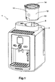
- La
figure 1 illustre une vue en perspective d'une machine à café automatique comportant un distributeur automatique de mouture selon un mode particulier de réalisation de l'invention. - La
figure 2 illustre une vue éclatée en perspective du distributeur automatique de mouture de la machine à café automatique de lafigure 1 . - La
figure 3 est une vue du dessus illustrant le siège du boîtier muni d'une languette de la machine à café automatique de lafigure 1 . - La
figure 4 est une vue en écorché partiel du dessous illustrant la roue crantée et le micro interrupteur du distributeur automatique de mouture de la machine à café automatique de lafigure 1 . - La
figure 5 est une vue schématique du circuit de commande du moteur entraînant le distributeur automatique de mouture de la machine à café automatique de lafigure 1 .
- The
figure 1 illustrates a perspective view of an automatic coffee machine comprising a vending machine grinding according to a particular embodiment of the invention. - The
figure 2 illustrates an exploded perspective view of the distributor automatic grinding machine automatic coffee machinefigure 1 . - The
figure 3 is a view from above showing the seat of the case provided with a tab of the automatic coffee machine of thefigure 1 . - The
figure 4 is a partial cutaway view of the underside illustrating the toothed wheel and the micro-switch of the automatic grinding machine of the automatic coffee machine of thefigure 1 . - The
figure 5 is a schematic view of the motor control circuit driving the automatic vending machine of the automatic coffee machine of thefigure 1 .
Les
Tel que visible sur la
Tel que visible sur la
Le réservoir 11 comporte, au dessus de la pièce support intermédiaire 17, un cône 30 muni de quatre pales 31 s'étendant latéralement et fixé sur la partie supérieure du moyeu cylindrique 16. Les pales 31 et le cône 30 en tournant transfèrent la mouture vers les palettes radiales rotatives 15 à travers des ouvertures 19 situées dans la pièce support intermédiaire 17.The
Les palettes 15 sont destinées à être entraînées par l'intermédiaire du moyeu 16, à l'aide d'un mécanisme rotatif de couplage 32, par des moyens moteur 40 fixés dans le boîtier 2 en vue de transférer par une ouverture d'écoulement 20 pratiquée latéralement et dans le fond du réservoir 11, une dose déterminée de mouture vers une sortie d'évacuation 5 formée dans le siège 3 et communiquant directement avec l'ouverture d'écoulement 20.The
L'ouverture d'écoulement 20 est constituée par une découpe 21 pratiquée dans la paroi latérale 12 du réservoir 11 entre la pièce support intermédiaire 17 et le fond 13 et par une découpe 22 pratiquée dans le fond 13 du réservoir 11 suivant un secteur annulaire circulaire.The
Le réservoir 11 comporte un volet rotatif escamotable 33 permettant d'obturer l'ouverture d'écoulement 20 lors du retrait du réservoir 11 de la machine à café automatique 1.The
La sortie d'évacuation 5 (
Lorsque le réservoir est retiré de la machine à café, la languette 6 empêche l'utilisateur d'insérer un doigt dans la sortie d'évacuation 5 du siège vers l'intérieur de la machine, ce qui peut être dangereux dans le cas d'un démarrage intempestif de la machine.When the reservoir is removed from the coffee machine, the
Après distribution de la dose déterminée de mouture, l'arrêt des moyens moteur 40 assure un positionnement des palettes radiales rotatives 15 tel que deux d'entre elles bordent l'ouverture d'écoulement 20 de façon à empêcher tout écoulement de la mouture.After distribution of the determined milling dose, the stopping of the motor means 40 ensures positioning of the radial
Les moyens moteur 40 (
La
Le circuit de commande 42 comprend un composant de protection formé par une résistance 56 qui permet de limiter le courant généré lors de l'arrêt du moteur 41 pour protéger le transistor 54 et de limiter le courant de court circuit lors des commutations des deux transistors 53, 54. La résistance 56 permet également d'assurer une fonction fusible en cas de défaillance de fonctionnement des transistors 53, 54.The
Le circuit de commande 42 comporte également une mémoire (non illustrée dans les figures) dans laquelle un type de café i est associé à un nombre Ni de huitième de tour du moyeu portant les palettes rotatives, ce nombre Ni de huitième de tour correspondant à une quantité de mouture Mi.The
En fonctionnement, l'utilisateur dispose de la mouture dans le réservoir 11 et le positionne dans le siège 3 du boîtier 2 de la machine à café automatique 1. Il commande ensuite la préparation d'un type de café i, ce qui va initier un cycle de distribution de mouture. Le circuit de commande 42 active la mise en marche du moteur 41 pour faire tourner les palettes rotatives 15 qui transfèrent la mouture vers la sortie d'évacuation 5 située dans le siège 3. Lorsque le circuit de commande 42 a détecté i changements d'état du micro interrupteur 47 générés par la rotation de la roue crantée 46, il commande l'arrêt du moteur 41 en coupant son alimentation, puis en court circuitant ses bornes 65, 66, ce qui provoque un arrêt précis des palettes rotatives 15.In operation, the user has the grinding in the
Bien entendu, l'invention n'est nullement limitée au mode de réalisation décrit et illustré qui n'a été donné qu'à titre d'exemple. Des modifications restent possibles, notamment du point de vue de la constitution des divers éléments ou par substitution d'équivalents techniques, sans sortir pour autant du domaine de protection de l'invention.Of course, the invention is not limited to the embodiment described and illustrated which has been given by way of example. Modifications are possible, particularly from the point of view of the constitution of the various elements or by substitution of technical equivalents, without departing from the scope of protection of the invention.
Ainsi, le circuit de commande coupe l'alimentation des moyens moteur et met en court-circuit les deux bornes de ces moyens moteur à l'aide de relais.Thus, the control circuit interrupts the power supply of the motor means and short-circuits the two terminals of these motor means with the aid of relays.
Dans une variante de réalisation, les moyens de détection de la position de la palette rotative sont constitués par un disque perforé et capteur optique.In an alternative embodiment, the means for detecting the position of the rotary vane are constituted by a perforated disk and an optical sensor.
Dans une autre variante de réalisation, les moyens de détection de la position de la palette rotative sont constitués par une roue supportant des aimants et un capteur à effet Hall.In another variant embodiment, the means for detecting the position of the rotary vane are constituted by a wheel supporting magnets and a Hall effect sensor.
Claims (7)
Applications Claiming Priority (1)
| Application Number | Priority Date | Filing Date | Title |
|---|---|---|---|
| FR0708607A FR2924590B1 (en) | 2007-12-11 | 2007-12-11 | AUTOMATIC COFFEE MACHINE WITH AUTOMATIC MILLING DISTRIBUTOR |
Publications (2)
| Publication Number | Publication Date |
|---|---|
| EP2070453A1 true EP2070453A1 (en) | 2009-06-17 |
| EP2070453B1 EP2070453B1 (en) | 2011-09-28 |
Family
ID=39495507
Family Applications (1)
| Application Number | Title | Priority Date | Filing Date |
|---|---|---|---|
| EP08356151A Not-in-force EP2070453B1 (en) | 2007-12-11 | 2008-12-09 | Automatische Kaffeemaschine mit automatischem Verteiler des Kaffeepulvers |
Country Status (4)
| Country | Link |
|---|---|
| US (1) | US8042455B2 (en) |
| EP (1) | EP2070453B1 (en) |
| AT (1) | ATE525942T1 (en) |
| FR (1) | FR2924590B1 (en) |
Cited By (1)
| Publication number | Priority date | Publication date | Assignee | Title |
|---|---|---|---|---|
| WO2012084964A1 (en) * | 2010-12-22 | 2012-06-28 | Nestec S.A. | System of a container for storing and dispensing a product and a machine for dosing the product |
Families Citing this family (10)
| Publication number | Priority date | Publication date | Assignee | Title |
|---|---|---|---|---|
| FR2931051B1 (en) * | 2008-05-16 | 2010-04-23 | Seb Sa | AUTOMATIC MOLDED COFFEE DISPENSER |
| US20120017765A1 (en) * | 2010-07-21 | 2012-01-26 | Simatelex Manufactory Co. Ltd. | Coffee maker having a bean grinder and coffee bean grinder |
| DE102010025530A1 (en) * | 2010-06-29 | 2012-03-01 | Eugster/Frismag Ag | Coffee machine with a position detection device and / or positioning speed detection device |
| CN105266588B (en) * | 2014-07-03 | 2018-01-23 | 中山市金富铤电器科技有限公司 | A kind of automatic rotation pumping water tap for tea set |
| US10436056B2 (en) | 2015-06-23 | 2019-10-08 | General Electric Company | Relative position measurement |
| FR3052044B1 (en) * | 2016-06-02 | 2018-05-18 | Seb S.A. | MILLING DISPENSER FOR COFFEE MACHINE PROVIDED WITH A CURVILINE BLADE TURBINE |
| USD824713S1 (en) | 2016-12-01 | 2018-08-07 | Hamilton Beach Brands, Inc. | Coffeemaker |
| US11019955B2 (en) | 2017-07-21 | 2021-06-01 | Hamilton Beach Brands, Inc. | Kitchen appliance for preparing a beverage and method of operating same |
| CN108175283A (en) * | 2018-02-10 | 2018-06-19 | 深圳前海小智萌品科技有限公司 | The lower powder device of rotation and powder brewing device |
| USD1007931S1 (en) * | 2022-02-03 | 2023-12-19 | Gruppo Cimbali S.P.A. | Coffee machine |
Citations (1)
| Publication number | Priority date | Publication date | Assignee | Title |
|---|---|---|---|---|
| FR2713906A1 (en) | 1993-12-20 | 1995-06-23 | Moulinex Sa | Automatic vending machine. |
Family Cites Families (10)
| Publication number | Priority date | Publication date | Assignee | Title |
|---|---|---|---|---|
| US1894815A (en) * | 1930-06-16 | 1933-01-17 | United Eng Foundry Co | Control system |
| US2441291A (en) * | 1944-09-09 | 1948-05-11 | Cincinnati Milling Machine Co | Spindle positioning mechanism |
| BE559426A (en) * | 1956-11-29 | |||
| US3415419A (en) * | 1966-10-27 | 1968-12-10 | Jewett | Fluid administering system |
| US4148415A (en) * | 1976-06-07 | 1979-04-10 | Florida Roy R | Automatic dispensing apparatus |
| US4651632A (en) * | 1985-12-13 | 1987-03-24 | Wuerttembergische Metallwarenfabrik Ag. | Coffee percolator |
| JPS6487982A (en) * | 1987-09-28 | 1989-04-03 | Matsushita Electric Ind Co Ltd | Hot water supplier |
| AU636286B2 (en) * | 1988-01-07 | 1993-04-29 | Bernard Hazon | Syringe-pushing device for ambulant administration of parenteral injections, with flow rate governed by the contents of the syringe |
| US5303639A (en) * | 1991-04-10 | 1994-04-19 | Bunn-O-Matic Corporation | Automatic brewer |
| FR2877556B1 (en) * | 2004-11-09 | 2006-12-08 | Seb Sa | AUTOMATIC DISPENSER OF INFINED BEVERAGES |
-
2007
- 2007-12-11 FR FR0708607A patent/FR2924590B1/en not_active Expired - Fee Related
-
2008
- 2008-12-09 EP EP08356151A patent/EP2070453B1/en not_active Not-in-force
- 2008-12-09 AT AT08356151T patent/ATE525942T1/en not_active IP Right Cessation
- 2008-12-11 US US12/332,786 patent/US8042455B2/en not_active Expired - Fee Related
Patent Citations (1)
| Publication number | Priority date | Publication date | Assignee | Title |
|---|---|---|---|---|
| FR2713906A1 (en) | 1993-12-20 | 1995-06-23 | Moulinex Sa | Automatic vending machine. |
Cited By (3)
| Publication number | Priority date | Publication date | Assignee | Title |
|---|---|---|---|---|
| WO2012084964A1 (en) * | 2010-12-22 | 2012-06-28 | Nestec S.A. | System of a container for storing and dispensing a product and a machine for dosing the product |
| JP2014500112A (en) * | 2010-12-22 | 2014-01-09 | ネステク ソシエテ アノニム | System comprising a container for storing and supplying the product and a machine for administering the product |
| US9635971B2 (en) | 2010-12-22 | 2017-05-02 | Nestec S.A. | System of a container for storing and dispensing a product and a machine for dosing the product |
Also Published As
| Publication number | Publication date |
|---|---|
| US8042455B2 (en) | 2011-10-25 |
| US20090145303A1 (en) | 2009-06-11 |
| EP2070453B1 (en) | 2011-09-28 |
| FR2924590A1 (en) | 2009-06-12 |
| FR2924590B1 (en) | 2009-11-13 |
| ATE525942T1 (en) | 2011-10-15 |
Similar Documents
| Publication | Publication Date | Title |
|---|---|---|
| EP2070453B1 (en) | Automatische Kaffeemaschine mit automatischem Verteiler des Kaffeepulvers | |
| EP0735836B1 (en) | Automatic ground grain dispenser | |
| BE1019670A3 (en) | CARTOUCHE DE CONDITIONNEMENT DE GRAINS DE CAFE, AND MACHINE A CAFE COMPRENANT CELLE-CI. | |
| EP2030540B1 (en) | Method for measuring the amount of coffee dispensed by a coffee grinder and device comprising such a grinder | |
| EP0280594A1 (en) | Detecting and signalling device for an automatic espresso coffee machine | |
| EP0452214A1 (en) | Coffee mill and coffee machine equipped with such a mill | |
| EP1266268B1 (en) | Watch winding device | |
| FR2927787A3 (en) | VENDING MACHINE | |
| CA2803739A1 (en) | Electrical power supply for equipment carried by a rotary support | |
| FR2921610A1 (en) | ADJUSTING DEVICE FOR A SEAT OF A MOTOR VEHICLE | |
| CH685323A5 (en) | Coffee grinder. | |
| EP1705115A1 (en) | Torque limiter having two mechanical inputs | |
| EP3306416B1 (en) | Mechanical clock movement with power-reserve detection | |
| FR2797694A1 (en) | OPENING ROOF CONTROL DEVICE | |
| EP2172143B1 (en) | Method for controlling the movement of a component of an electrical household appliance, in particular a control panel of a baking oven | |
| EP1408461B1 (en) | Cup conveying system in an automatic vending machine for drinks | |
| FR2921595A1 (en) | Adjuster for adjusting motor vehicle seat, has electric motor with speed rating of specified range of rotations per minute at rated voltage, and electric motor and drive accommodated in common housing | |
| EP0732438A1 (en) | Device incorporated in an electric motor for a washing machine, a dishwasher or similar | |
| WO2018042121A1 (en) | Electric motor with a brush holder for a starter | |
| FR2633448A1 (en) | Automatic re-engagement device for circuit breaker | |
| EP4154394A1 (en) | Device for braking a rotating tool in a cooking apparatus | |
| CH707984A2 (en) | reassembly function housing for self-winding watch. | |
| CH554029A (en) | Distributor for ice chips and flakes - delivering definite quantities into a receptacle | |
| FR2997214A3 (en) | Anti-fraud device for coin distributer, has set of moving parts, where coin distributer is providing in locking position, and release position in which moving parts do not produce mechanical locking of coin distributer | |
| FR2951963A1 (en) | Centrifuge for centrifuging products contained in container in biological field, has neutralization units coupled with detection unit in order to inactivate launching control when horizontal defect is detected |
Legal Events
| Date | Code | Title | Description |
|---|---|---|---|
| PUAI | Public reference made under article 153(3) epc to a published international application that has entered the european phase |
Free format text: ORIGINAL CODE: 0009012 |
|
| AK | Designated contracting states |
Kind code of ref document: A1 Designated state(s): AT BE BG CH CY CZ DE DK EE ES FI FR GB GR HR HU IE IS IT LI LT LU LV MC MT NL NO PL PT RO SE SI SK TR |
|
| AX | Request for extension of the european patent |
Extension state: AL BA MK RS |
|
| 17P | Request for examination filed |
Effective date: 20090805 |
|
| AKX | Designation fees paid |
Designated state(s): AT BE BG CH CY CZ DE DK EE ES FI FR GB GR HR HU IE IS IT LI LT LU LV MC MT NL NO PL PT RO SE SI SK TR |
|
| GRAP | Despatch of communication of intention to grant a patent |
Free format text: ORIGINAL CODE: EPIDOSNIGR1 |
|
| GRAS | Grant fee paid |
Free format text: ORIGINAL CODE: EPIDOSNIGR3 |
|
| GRAA | (expected) grant |
Free format text: ORIGINAL CODE: 0009210 |
|
| AK | Designated contracting states |
Kind code of ref document: B1 Designated state(s): AT BE BG CH CY CZ DE DK EE ES FI FR GB GR HR HU IE IS IT LI LT LU LV MC MT NL NO PL PT RO SE SI SK TR |
|
| REG | Reference to a national code |
Ref country code: GB Ref legal event code: FG4D Free format text: NOT ENGLISH |
|
| REG | Reference to a national code |
Ref country code: CH Ref legal event code: EP |
|
| REG | Reference to a national code |
Ref country code: IE Ref legal event code: FG4D |
|
| REG | Reference to a national code |
Ref country code: DE Ref legal event code: R096 Ref document number: 602008010121 Country of ref document: DE Effective date: 20111222 |
|
| REG | Reference to a national code |
Ref country code: NL Ref legal event code: VDEP Effective date: 20110928 |
|
| PG25 | Lapsed in a contracting state [announced via postgrant information from national office to epo] |
Ref country code: SE Free format text: LAPSE BECAUSE OF FAILURE TO SUBMIT A TRANSLATION OF THE DESCRIPTION OR TO PAY THE FEE WITHIN THE PRESCRIBED TIME-LIMIT Effective date: 20110928 Ref country code: LT Free format text: LAPSE BECAUSE OF FAILURE TO SUBMIT A TRANSLATION OF THE DESCRIPTION OR TO PAY THE FEE WITHIN THE PRESCRIBED TIME-LIMIT Effective date: 20110928 Ref country code: NO Free format text: LAPSE BECAUSE OF FAILURE TO SUBMIT A TRANSLATION OF THE DESCRIPTION OR TO PAY THE FEE WITHIN THE PRESCRIBED TIME-LIMIT Effective date: 20111228 Ref country code: HR Free format text: LAPSE BECAUSE OF FAILURE TO SUBMIT A TRANSLATION OF THE DESCRIPTION OR TO PAY THE FEE WITHIN THE PRESCRIBED TIME-LIMIT Effective date: 20110928 Ref country code: FI Free format text: LAPSE BECAUSE OF FAILURE TO SUBMIT A TRANSLATION OF THE DESCRIPTION OR TO PAY THE FEE WITHIN THE PRESCRIBED TIME-LIMIT Effective date: 20110928 |
|
| LTIE | Lt: invalidation of european patent or patent extension |
Effective date: 20110928 |
|
| PG25 | Lapsed in a contracting state [announced via postgrant information from national office to epo] |
Ref country code: CY Free format text: LAPSE BECAUSE OF FAILURE TO SUBMIT A TRANSLATION OF THE DESCRIPTION OR TO PAY THE FEE WITHIN THE PRESCRIBED TIME-LIMIT Effective date: 20110928 Ref country code: LV Free format text: LAPSE BECAUSE OF FAILURE TO SUBMIT A TRANSLATION OF THE DESCRIPTION OR TO PAY THE FEE WITHIN THE PRESCRIBED TIME-LIMIT Effective date: 20110928 Ref country code: GR Free format text: LAPSE BECAUSE OF FAILURE TO SUBMIT A TRANSLATION OF THE DESCRIPTION OR TO PAY THE FEE WITHIN THE PRESCRIBED TIME-LIMIT Effective date: 20111229 Ref country code: AT Free format text: LAPSE BECAUSE OF FAILURE TO SUBMIT A TRANSLATION OF THE DESCRIPTION OR TO PAY THE FEE WITHIN THE PRESCRIBED TIME-LIMIT Effective date: 20110928 Ref country code: SI Free format text: LAPSE BECAUSE OF FAILURE TO SUBMIT A TRANSLATION OF THE DESCRIPTION OR TO PAY THE FEE WITHIN THE PRESCRIBED TIME-LIMIT Effective date: 20110928 |
|
| REG | Reference to a national code |
Ref country code: AT Ref legal event code: MK05 Ref document number: 525942 Country of ref document: AT Kind code of ref document: T Effective date: 20110928 |
|
| REG | Reference to a national code |
Ref country code: IE Ref legal event code: FD4D |
|
| PG25 | Lapsed in a contracting state [announced via postgrant information from national office to epo] |
Ref country code: SK Free format text: LAPSE BECAUSE OF FAILURE TO SUBMIT A TRANSLATION OF THE DESCRIPTION OR TO PAY THE FEE WITHIN THE PRESCRIBED TIME-LIMIT Effective date: 20110928 Ref country code: IS Free format text: LAPSE BECAUSE OF FAILURE TO SUBMIT A TRANSLATION OF THE DESCRIPTION OR TO PAY THE FEE WITHIN THE PRESCRIBED TIME-LIMIT Effective date: 20120128 Ref country code: CZ Free format text: LAPSE BECAUSE OF FAILURE TO SUBMIT A TRANSLATION OF THE DESCRIPTION OR TO PAY THE FEE WITHIN THE PRESCRIBED TIME-LIMIT Effective date: 20110928 |
|
| PG25 | Lapsed in a contracting state [announced via postgrant information from national office to epo] |
Ref country code: RO Free format text: LAPSE BECAUSE OF FAILURE TO SUBMIT A TRANSLATION OF THE DESCRIPTION OR TO PAY THE FEE WITHIN THE PRESCRIBED TIME-LIMIT Effective date: 20110928 Ref country code: NL Free format text: LAPSE BECAUSE OF FAILURE TO SUBMIT A TRANSLATION OF THE DESCRIPTION OR TO PAY THE FEE WITHIN THE PRESCRIBED TIME-LIMIT Effective date: 20110928 Ref country code: PT Free format text: LAPSE BECAUSE OF FAILURE TO SUBMIT A TRANSLATION OF THE DESCRIPTION OR TO PAY THE FEE WITHIN THE PRESCRIBED TIME-LIMIT Effective date: 20120130 Ref country code: EE Free format text: LAPSE BECAUSE OF FAILURE TO SUBMIT A TRANSLATION OF THE DESCRIPTION OR TO PAY THE FEE WITHIN THE PRESCRIBED TIME-LIMIT Effective date: 20110928 |
|
| BERE | Be: lapsed |
Owner name: SEB S.A. Effective date: 20111231 |
|
| PG25 | Lapsed in a contracting state [announced via postgrant information from national office to epo] |
Ref country code: IE Free format text: LAPSE BECAUSE OF FAILURE TO SUBMIT A TRANSLATION OF THE DESCRIPTION OR TO PAY THE FEE WITHIN THE PRESCRIBED TIME-LIMIT Effective date: 20110928 Ref country code: MC Free format text: LAPSE BECAUSE OF NON-PAYMENT OF DUE FEES Effective date: 20111231 Ref country code: DK Free format text: LAPSE BECAUSE OF FAILURE TO SUBMIT A TRANSLATION OF THE DESCRIPTION OR TO PAY THE FEE WITHIN THE PRESCRIBED TIME-LIMIT Effective date: 20110928 |
|
| PLBE | No opposition filed within time limit |
Free format text: ORIGINAL CODE: 0009261 |
|
| STAA | Information on the status of an ep patent application or granted ep patent |
Free format text: STATUS: NO OPPOSITION FILED WITHIN TIME LIMIT |
|
| PG25 | Lapsed in a contracting state [announced via postgrant information from national office to epo] |
Ref country code: PL Free format text: LAPSE BECAUSE OF FAILURE TO SUBMIT A TRANSLATION OF THE DESCRIPTION OR TO PAY THE FEE WITHIN THE PRESCRIBED TIME-LIMIT Effective date: 20110928 |
|
| 26N | No opposition filed |
Effective date: 20120629 |
|
| REG | Reference to a national code |
Ref country code: DE Ref legal event code: R097 Ref document number: 602008010121 Country of ref document: DE Effective date: 20120629 |
|
| PG25 | Lapsed in a contracting state [announced via postgrant information from national office to epo] |
Ref country code: BE Free format text: LAPSE BECAUSE OF NON-PAYMENT OF DUE FEES Effective date: 20111231 |
|
| PG25 | Lapsed in a contracting state [announced via postgrant information from national office to epo] |
Ref country code: MT Free format text: LAPSE BECAUSE OF FAILURE TO SUBMIT A TRANSLATION OF THE DESCRIPTION OR TO PAY THE FEE WITHIN THE PRESCRIBED TIME-LIMIT Effective date: 20110928 |
|
| PG25 | Lapsed in a contracting state [announced via postgrant information from national office to epo] |
Ref country code: ES Free format text: LAPSE BECAUSE OF FAILURE TO SUBMIT A TRANSLATION OF THE DESCRIPTION OR TO PAY THE FEE WITHIN THE PRESCRIBED TIME-LIMIT Effective date: 20120108 |
|
| PG25 | Lapsed in a contracting state [announced via postgrant information from national office to epo] |
Ref country code: LU Free format text: LAPSE BECAUSE OF NON-PAYMENT OF DUE FEES Effective date: 20111209 |
|
| PG25 | Lapsed in a contracting state [announced via postgrant information from national office to epo] |
Ref country code: BG Free format text: LAPSE BECAUSE OF FAILURE TO SUBMIT A TRANSLATION OF THE DESCRIPTION OR TO PAY THE FEE WITHIN THE PRESCRIBED TIME-LIMIT Effective date: 20111228 |
|
| PG25 | Lapsed in a contracting state [announced via postgrant information from national office to epo] |
Ref country code: TR Free format text: LAPSE BECAUSE OF FAILURE TO SUBMIT A TRANSLATION OF THE DESCRIPTION OR TO PAY THE FEE WITHIN THE PRESCRIBED TIME-LIMIT Effective date: 20110928 |
|
| PG25 | Lapsed in a contracting state [announced via postgrant information from national office to epo] |
Ref country code: HU Free format text: LAPSE BECAUSE OF FAILURE TO SUBMIT A TRANSLATION OF THE DESCRIPTION OR TO PAY THE FEE WITHIN THE PRESCRIBED TIME-LIMIT Effective date: 20110928 |
|
| REG | Reference to a national code |
Ref country code: FR Ref legal event code: PLFP Year of fee payment: 8 |
|
| PGFP | Annual fee paid to national office [announced via postgrant information from national office to epo] |
Ref country code: GB Payment date: 20151218 Year of fee payment: 8 Ref country code: CH Payment date: 20151207 Year of fee payment: 8 Ref country code: IT Payment date: 20151215 Year of fee payment: 8 |
|
| REG | Reference to a national code |
Ref country code: FR Ref legal event code: PLFP Year of fee payment: 9 |
|
| REG | Reference to a national code |
Ref country code: FR Ref legal event code: CA Effective date: 20170518 |
|
| REG | Reference to a national code |
Ref country code: CH Ref legal event code: PL |
|
| GBPC | Gb: european patent ceased through non-payment of renewal fee |
Effective date: 20161209 |
|
| PG25 | Lapsed in a contracting state [announced via postgrant information from national office to epo] |
Ref country code: IT Free format text: LAPSE BECAUSE OF NON-PAYMENT OF DUE FEES Effective date: 20161209 Ref country code: CH Free format text: LAPSE BECAUSE OF NON-PAYMENT OF DUE FEES Effective date: 20161231 Ref country code: LI Free format text: LAPSE BECAUSE OF NON-PAYMENT OF DUE FEES Effective date: 20161231 |
|
| PG25 | Lapsed in a contracting state [announced via postgrant information from national office to epo] |
Ref country code: GB Free format text: LAPSE BECAUSE OF NON-PAYMENT OF DUE FEES Effective date: 20161209 |
|
| REG | Reference to a national code |
Ref country code: FR Ref legal event code: PLFP Year of fee payment: 10 |
|
| PGFP | Annual fee paid to national office [announced via postgrant information from national office to epo] |
Ref country code: DE Payment date: 20171212 Year of fee payment: 10 |
|
| PGFP | Annual fee paid to national office [announced via postgrant information from national office to epo] |
Ref country code: FR Payment date: 20180102 Year of fee payment: 10 |
|
| REG | Reference to a national code |
Ref country code: DE Ref legal event code: R119 Ref document number: 602008010121 Country of ref document: DE |
|
| PG25 | Lapsed in a contracting state [announced via postgrant information from national office to epo] |
Ref country code: DE Free format text: LAPSE BECAUSE OF NON-PAYMENT OF DUE FEES Effective date: 20190702 Ref country code: FR Free format text: LAPSE BECAUSE OF NON-PAYMENT OF DUE FEES Effective date: 20181231 |