EP2069553B1 - Workpiece with hard coating - Google Patents
Workpiece with hard coating Download PDFInfo
- Publication number
- EP2069553B1 EP2069553B1 EP07803079.8A EP07803079A EP2069553B1 EP 2069553 B1 EP2069553 B1 EP 2069553B1 EP 07803079 A EP07803079 A EP 07803079A EP 2069553 B1 EP2069553 B1 EP 2069553B1
- Authority
- EP
- European Patent Office
- Prior art keywords
- workpiece
- layer
- interlayer
- cutting
- addressed
- Prior art date
- Legal status (The legal status is an assumption and is not a legal conclusion. Google has not performed a legal analysis and makes no representation as to the accuracy of the status listed.)
- Active
Links
- 238000000576 coating method Methods 0.000 title claims description 99
- 239000011248 coating agent Substances 0.000 title claims description 88
- 239000010410 layer Substances 0.000 claims description 117
- 238000005520 cutting process Methods 0.000 claims description 62
- 239000011229 interlayer Substances 0.000 claims description 61
- 239000000463 material Substances 0.000 claims description 37
- 229910010037 TiAlN Inorganic materials 0.000 claims description 29
- 239000000203 mixture Substances 0.000 claims description 26
- 238000004519 manufacturing process Methods 0.000 claims description 10
- 229910000760 Hardened steel Inorganic materials 0.000 claims description 6
- 229910052721 tungsten Inorganic materials 0.000 claims description 6
- 229910052750 molybdenum Inorganic materials 0.000 claims description 5
- 229910052715 tantalum Inorganic materials 0.000 claims description 5
- 229910052582 BN Inorganic materials 0.000 claims description 4
- PZNSFCLAULLKQX-UHFFFAOYSA-N Boron nitride Chemical compound N#B PZNSFCLAULLKQX-UHFFFAOYSA-N 0.000 claims description 4
- 229910000997 High-speed steel Inorganic materials 0.000 claims description 4
- 229910010293 ceramic material Inorganic materials 0.000 claims description 4
- 239000011195 cermet Substances 0.000 claims description 4
- 229910052758 niobium Inorganic materials 0.000 claims 1
- 238000000034 method Methods 0.000 description 12
- 238000000151 deposition Methods 0.000 description 11
- 230000008021 deposition Effects 0.000 description 11
- 238000012360 testing method Methods 0.000 description 11
- 238000003801 milling Methods 0.000 description 10
- 238000001878 scanning electron micrograph Methods 0.000 description 10
- 239000002356 single layer Substances 0.000 description 9
- 239000010936 titanium Substances 0.000 description 9
- 238000005240 physical vapour deposition Methods 0.000 description 8
- 238000002441 X-ray diffraction Methods 0.000 description 7
- 230000001680 brushing effect Effects 0.000 description 6
- 230000008020 evaporation Effects 0.000 description 6
- 238000001704 evaporation Methods 0.000 description 6
- 229910052782 aluminium Inorganic materials 0.000 description 5
- 239000002826 coolant Substances 0.000 description 5
- 230000003647 oxidation Effects 0.000 description 5
- 238000007254 oxidation reaction Methods 0.000 description 5
- 238000012545 processing Methods 0.000 description 5
- 238000001228 spectrum Methods 0.000 description 5
- 239000000758 substrate Substances 0.000 description 5
- 229910000831 Steel Inorganic materials 0.000 description 4
- 229910052796 boron Inorganic materials 0.000 description 4
- 239000011651 chromium Substances 0.000 description 4
- 239000010959 steel Substances 0.000 description 4
- XAGFODPZIPBFFR-UHFFFAOYSA-N aluminium Chemical compound [Al] XAGFODPZIPBFFR-UHFFFAOYSA-N 0.000 description 3
- 230000000052 comparative effect Effects 0.000 description 3
- 230000000694 effects Effects 0.000 description 3
- 239000012071 phase Substances 0.000 description 3
- 239000013077 target material Substances 0.000 description 3
- 229910010038 TiAl Inorganic materials 0.000 description 2
- 229910008482 TiSiN Inorganic materials 0.000 description 2
- 238000013459 approach Methods 0.000 description 2
- 229910002091 carbon monoxide Inorganic materials 0.000 description 2
- 229910052804 chromium Inorganic materials 0.000 description 2
- 238000001816 cooling Methods 0.000 description 2
- 239000013078 crystal Substances 0.000 description 2
- 238000005553 drilling Methods 0.000 description 2
- 239000000839 emulsion Substances 0.000 description 2
- 239000011159 matrix material Substances 0.000 description 2
- 229910052751 metal Inorganic materials 0.000 description 2
- 239000002184 metal Substances 0.000 description 2
- 239000002480 mineral oil Substances 0.000 description 2
- 235000010446 mineral oil Nutrition 0.000 description 2
- 238000000623 plasma-assisted chemical vapour deposition Methods 0.000 description 2
- 229910052719 titanium Inorganic materials 0.000 description 2
- ZOXJGFHDIHLPTG-UHFFFAOYSA-N Boron Chemical compound [B] ZOXJGFHDIHLPTG-UHFFFAOYSA-N 0.000 description 1
- VYZAMTAEIAYCRO-UHFFFAOYSA-N Chromium Chemical compound [Cr] VYZAMTAEIAYCRO-UHFFFAOYSA-N 0.000 description 1
- 229910000822 Cold-work tool steel Inorganic materials 0.000 description 1
- 239000004677 Nylon Substances 0.000 description 1
- ATJFFYVFTNAWJD-UHFFFAOYSA-N Tin Chemical compound [Sn] ATJFFYVFTNAWJD-UHFFFAOYSA-N 0.000 description 1
- RTAQQCXQSZGOHL-UHFFFAOYSA-N Titanium Chemical compound [Ti] RTAQQCXQSZGOHL-UHFFFAOYSA-N 0.000 description 1
- 229910001315 Tool steel Inorganic materials 0.000 description 1
- 229910009043 WC-Co Inorganic materials 0.000 description 1
- PNEYBMLMFCGWSK-UHFFFAOYSA-N aluminium oxide Inorganic materials [O-2].[O-2].[O-2].[Al+3].[Al+3] PNEYBMLMFCGWSK-UHFFFAOYSA-N 0.000 description 1
- 230000015556 catabolic process Effects 0.000 description 1
- 238000005229 chemical vapour deposition Methods 0.000 description 1
- 239000011247 coating layer Substances 0.000 description 1
- 229910052593 corundum Inorganic materials 0.000 description 1
- 238000006731 degradation reaction Methods 0.000 description 1
- 230000001419 dependent effect Effects 0.000 description 1
- 238000005516 engineering process Methods 0.000 description 1
- 239000007792 gaseous phase Substances 0.000 description 1
- 238000000227 grinding Methods 0.000 description 1
- 238000010438 heat treatment Methods 0.000 description 1
- 238000010348 incorporation Methods 0.000 description 1
- 238000007733 ion plating Methods 0.000 description 1
- QRXWMOHMRWLFEY-UHFFFAOYSA-N isoniazide Chemical compound NNC(=O)C1=CC=NC=C1 QRXWMOHMRWLFEY-UHFFFAOYSA-N 0.000 description 1
- 230000001050 lubricating effect Effects 0.000 description 1
- 238000003754 machining Methods 0.000 description 1
- 238000001755 magnetron sputter deposition Methods 0.000 description 1
- 238000005259 measurement Methods 0.000 description 1
- 229920001778 nylon Polymers 0.000 description 1
- 238000005334 plasma enhanced chemical vapour deposition Methods 0.000 description 1
- 230000001902 propagating effect Effects 0.000 description 1
- 239000007779 soft material Substances 0.000 description 1
- 239000007787 solid Substances 0.000 description 1
- 238000004544 sputter deposition Methods 0.000 description 1
- 239000010409 thin film Substances 0.000 description 1
- 150000003609 titanium compounds Chemical class 0.000 description 1
- WFKWXMTUELFFGS-UHFFFAOYSA-N tungsten Chemical compound [W] WFKWXMTUELFFGS-UHFFFAOYSA-N 0.000 description 1
- 239000010937 tungsten Substances 0.000 description 1
- UONOETXJSWQNOL-UHFFFAOYSA-N tungsten carbide Chemical compound [W+]#[C-] UONOETXJSWQNOL-UHFFFAOYSA-N 0.000 description 1
- 238000001771 vacuum deposition Methods 0.000 description 1
- 229910001845 yogo sapphire Inorganic materials 0.000 description 1
Images
Classifications
-
- C—CHEMISTRY; METALLURGY
- C23—COATING METALLIC MATERIAL; COATING MATERIAL WITH METALLIC MATERIAL; CHEMICAL SURFACE TREATMENT; DIFFUSION TREATMENT OF METALLIC MATERIAL; COATING BY VACUUM EVAPORATION, BY SPUTTERING, BY ION IMPLANTATION OR BY CHEMICAL VAPOUR DEPOSITION, IN GENERAL; INHIBITING CORROSION OF METALLIC MATERIAL OR INCRUSTATION IN GENERAL
- C23C—COATING METALLIC MATERIAL; COATING MATERIAL WITH METALLIC MATERIAL; SURFACE TREATMENT OF METALLIC MATERIAL BY DIFFUSION INTO THE SURFACE, BY CHEMICAL CONVERSION OR SUBSTITUTION; COATING BY VACUUM EVAPORATION, BY SPUTTERING, BY ION IMPLANTATION OR BY CHEMICAL VAPOUR DEPOSITION, IN GENERAL
- C23C14/00—Coating by vacuum evaporation, by sputtering or by ion implantation of the coating forming material
- C23C14/06—Coating by vacuum evaporation, by sputtering or by ion implantation of the coating forming material characterised by the coating material
- C23C14/0641—Nitrides
-
- C—CHEMISTRY; METALLURGY
- C08—ORGANIC MACROMOLECULAR COMPOUNDS; THEIR PREPARATION OR CHEMICAL WORKING-UP; COMPOSITIONS BASED THEREON
- C08J—WORKING-UP; GENERAL PROCESSES OF COMPOUNDING; AFTER-TREATMENT NOT COVERED BY SUBCLASSES C08B, C08C, C08F, C08G or C08H
- C08J7/00—Chemical treatment or coating of shaped articles made of macromolecular substances
- C08J7/04—Coating
- C08J7/0427—Coating with only one layer of a composition containing a polymer binder
-
- C—CHEMISTRY; METALLURGY
- C08—ORGANIC MACROMOLECULAR COMPOUNDS; THEIR PREPARATION OR CHEMICAL WORKING-UP; COMPOSITIONS BASED THEREON
- C08J—WORKING-UP; GENERAL PROCESSES OF COMPOUNDING; AFTER-TREATMENT NOT COVERED BY SUBCLASSES C08B, C08C, C08F, C08G or C08H
- C08J7/00—Chemical treatment or coating of shaped articles made of macromolecular substances
- C08J7/04—Coating
- C08J7/046—Forming abrasion-resistant coatings; Forming surface-hardening coatings
-
- C—CHEMISTRY; METALLURGY
- C08—ORGANIC MACROMOLECULAR COMPOUNDS; THEIR PREPARATION OR CHEMICAL WORKING-UP; COMPOSITIONS BASED THEREON
- C08J—WORKING-UP; GENERAL PROCESSES OF COMPOUNDING; AFTER-TREATMENT NOT COVERED BY SUBCLASSES C08B, C08C, C08F, C08G or C08H
- C08J7/00—Chemical treatment or coating of shaped articles made of macromolecular substances
- C08J7/12—Chemical modification
- C08J7/123—Treatment by wave energy or particle radiation
-
- C—CHEMISTRY; METALLURGY
- C23—COATING METALLIC MATERIAL; COATING MATERIAL WITH METALLIC MATERIAL; CHEMICAL SURFACE TREATMENT; DIFFUSION TREATMENT OF METALLIC MATERIAL; COATING BY VACUUM EVAPORATION, BY SPUTTERING, BY ION IMPLANTATION OR BY CHEMICAL VAPOUR DEPOSITION, IN GENERAL; INHIBITING CORROSION OF METALLIC MATERIAL OR INCRUSTATION IN GENERAL
- C23C—COATING METALLIC MATERIAL; COATING MATERIAL WITH METALLIC MATERIAL; SURFACE TREATMENT OF METALLIC MATERIAL BY DIFFUSION INTO THE SURFACE, BY CHEMICAL CONVERSION OR SUBSTITUTION; COATING BY VACUUM EVAPORATION, BY SPUTTERING, BY ION IMPLANTATION OR BY CHEMICAL VAPOUR DEPOSITION, IN GENERAL
- C23C14/00—Coating by vacuum evaporation, by sputtering or by ion implantation of the coating forming material
- C23C14/22—Coating by vacuum evaporation, by sputtering or by ion implantation of the coating forming material characterised by the process of coating
- C23C14/24—Vacuum evaporation
- C23C14/32—Vacuum evaporation by explosion; by evaporation and subsequent ionisation of the vapours, e.g. ion-plating
- C23C14/325—Electric arc evaporation
-
- C—CHEMISTRY; METALLURGY
- C23—COATING METALLIC MATERIAL; COATING MATERIAL WITH METALLIC MATERIAL; CHEMICAL SURFACE TREATMENT; DIFFUSION TREATMENT OF METALLIC MATERIAL; COATING BY VACUUM EVAPORATION, BY SPUTTERING, BY ION IMPLANTATION OR BY CHEMICAL VAPOUR DEPOSITION, IN GENERAL; INHIBITING CORROSION OF METALLIC MATERIAL OR INCRUSTATION IN GENERAL
- C23C—COATING METALLIC MATERIAL; COATING MATERIAL WITH METALLIC MATERIAL; SURFACE TREATMENT OF METALLIC MATERIAL BY DIFFUSION INTO THE SURFACE, BY CHEMICAL CONVERSION OR SUBSTITUTION; COATING BY VACUUM EVAPORATION, BY SPUTTERING, BY ION IMPLANTATION OR BY CHEMICAL VAPOUR DEPOSITION, IN GENERAL
- C23C14/00—Coating by vacuum evaporation, by sputtering or by ion implantation of the coating forming material
- C23C14/22—Coating by vacuum evaporation, by sputtering or by ion implantation of the coating forming material characterised by the process of coating
- C23C14/34—Sputtering
-
- C—CHEMISTRY; METALLURGY
- C23—COATING METALLIC MATERIAL; COATING MATERIAL WITH METALLIC MATERIAL; CHEMICAL SURFACE TREATMENT; DIFFUSION TREATMENT OF METALLIC MATERIAL; COATING BY VACUUM EVAPORATION, BY SPUTTERING, BY ION IMPLANTATION OR BY CHEMICAL VAPOUR DEPOSITION, IN GENERAL; INHIBITING CORROSION OF METALLIC MATERIAL OR INCRUSTATION IN GENERAL
- C23C—COATING METALLIC MATERIAL; COATING MATERIAL WITH METALLIC MATERIAL; SURFACE TREATMENT OF METALLIC MATERIAL BY DIFFUSION INTO THE SURFACE, BY CHEMICAL CONVERSION OR SUBSTITUTION; COATING BY VACUUM EVAPORATION, BY SPUTTERING, BY ION IMPLANTATION OR BY CHEMICAL VAPOUR DEPOSITION, IN GENERAL
- C23C14/00—Coating by vacuum evaporation, by sputtering or by ion implantation of the coating forming material
- C23C14/58—After-treatment
-
- C—CHEMISTRY; METALLURGY
- C23—COATING METALLIC MATERIAL; COATING MATERIAL WITH METALLIC MATERIAL; CHEMICAL SURFACE TREATMENT; DIFFUSION TREATMENT OF METALLIC MATERIAL; COATING BY VACUUM EVAPORATION, BY SPUTTERING, BY ION IMPLANTATION OR BY CHEMICAL VAPOUR DEPOSITION, IN GENERAL; INHIBITING CORROSION OF METALLIC MATERIAL OR INCRUSTATION IN GENERAL
- C23C—COATING METALLIC MATERIAL; COATING MATERIAL WITH METALLIC MATERIAL; SURFACE TREATMENT OF METALLIC MATERIAL BY DIFFUSION INTO THE SURFACE, BY CHEMICAL CONVERSION OR SUBSTITUTION; COATING BY VACUUM EVAPORATION, BY SPUTTERING, BY ION IMPLANTATION OR BY CHEMICAL VAPOUR DEPOSITION, IN GENERAL
- C23C28/00—Coating for obtaining at least two superposed coatings either by methods not provided for in a single one of groups C23C2/00 - C23C26/00 or by combinations of methods provided for in subclasses C23C and C25C or C25D
- C23C28/04—Coating for obtaining at least two superposed coatings either by methods not provided for in a single one of groups C23C2/00 - C23C26/00 or by combinations of methods provided for in subclasses C23C and C25C or C25D only coatings of inorganic non-metallic material
- C23C28/044—Coating for obtaining at least two superposed coatings either by methods not provided for in a single one of groups C23C2/00 - C23C26/00 or by combinations of methods provided for in subclasses C23C and C25C or C25D only coatings of inorganic non-metallic material coatings specially adapted for cutting tools or wear applications
-
- C—CHEMISTRY; METALLURGY
- C23—COATING METALLIC MATERIAL; COATING MATERIAL WITH METALLIC MATERIAL; CHEMICAL SURFACE TREATMENT; DIFFUSION TREATMENT OF METALLIC MATERIAL; COATING BY VACUUM EVAPORATION, BY SPUTTERING, BY ION IMPLANTATION OR BY CHEMICAL VAPOUR DEPOSITION, IN GENERAL; INHIBITING CORROSION OF METALLIC MATERIAL OR INCRUSTATION IN GENERAL
- C23C—COATING METALLIC MATERIAL; COATING MATERIAL WITH METALLIC MATERIAL; SURFACE TREATMENT OF METALLIC MATERIAL BY DIFFUSION INTO THE SURFACE, BY CHEMICAL CONVERSION OR SUBSTITUTION; COATING BY VACUUM EVAPORATION, BY SPUTTERING, BY ION IMPLANTATION OR BY CHEMICAL VAPOUR DEPOSITION, IN GENERAL
- C23C28/00—Coating for obtaining at least two superposed coatings either by methods not provided for in a single one of groups C23C2/00 - C23C26/00 or by combinations of methods provided for in subclasses C23C and C25C or C25D
- C23C28/40—Coatings including alternating layers following a pattern, a periodic or defined repetition
- C23C28/42—Coatings including alternating layers following a pattern, a periodic or defined repetition characterized by the composition of the alternating layers
-
- C—CHEMISTRY; METALLURGY
- C23—COATING METALLIC MATERIAL; COATING MATERIAL WITH METALLIC MATERIAL; CHEMICAL SURFACE TREATMENT; DIFFUSION TREATMENT OF METALLIC MATERIAL; COATING BY VACUUM EVAPORATION, BY SPUTTERING, BY ION IMPLANTATION OR BY CHEMICAL VAPOUR DEPOSITION, IN GENERAL; INHIBITING CORROSION OF METALLIC MATERIAL OR INCRUSTATION IN GENERAL
- C23C—COATING METALLIC MATERIAL; COATING MATERIAL WITH METALLIC MATERIAL; SURFACE TREATMENT OF METALLIC MATERIAL BY DIFFUSION INTO THE SURFACE, BY CHEMICAL CONVERSION OR SUBSTITUTION; COATING BY VACUUM EVAPORATION, BY SPUTTERING, BY ION IMPLANTATION OR BY CHEMICAL VAPOUR DEPOSITION, IN GENERAL
- C23C30/00—Coating with metallic material characterised only by the composition of the metallic material, i.e. not characterised by the coating process
- C23C30/005—Coating with metallic material characterised only by the composition of the metallic material, i.e. not characterised by the coating process on hard metal substrates
-
- Y—GENERAL TAGGING OF NEW TECHNOLOGICAL DEVELOPMENTS; GENERAL TAGGING OF CROSS-SECTIONAL TECHNOLOGIES SPANNING OVER SEVERAL SECTIONS OF THE IPC; TECHNICAL SUBJECTS COVERED BY FORMER USPC CROSS-REFERENCE ART COLLECTIONS [XRACs] AND DIGESTS
- Y10—TECHNICAL SUBJECTS COVERED BY FORMER USPC
- Y10T—TECHNICAL SUBJECTS COVERED BY FORMER US CLASSIFICATION
- Y10T83/00—Cutting
- Y10T83/04—Processes
Definitions
- the present invention is directed to a workpiece having a body and a wear-resistant hard coating system on at least a part of its surface, further to a method of manufacturing a device.
- TiAlN is a coating which is widely used to machine hardened steel and is customarily applied by a PVD process.
- PVD physical vapour deposition process
- TiAlN layers used as a single layer- or in multilayersystems with sublayers of different Ti/Al/N stochiometries can be used up to working temperatures of 900°C at most for tooling application due to the incipient degradation of hardness at temperatures higher than 800 to 850°C depending on the Aluminum/Titanium ratio.
- the US 2005-0003239 proposes to apply AlCrN coatings to workpieces so as to increase their oxidation resistance.
- This coating is known to have a good oxidation resistance and a hot hardness up to 1100°C depending on the Aluminum/Chromium ratio. It is further referred to similar proposals in the WO 2006/005217 , the WO 2006/084404 and the US 2006-0222893 trying to further improve oxidation resitance and/or hot hardness of the coatings by using different multilayers and/or by introducing other elements into the AlCrN matrix.
- the US 2006-0269789 discloses a hard multilayer to cut high hardness material at a high speed.
- the hard multilayer comprises a first TiAlCrNX-based layer, wherein X stands for C or O.
- a second layer consists of a mixture of TiAlCrNX and of TiAl(SiC)NX or is a multilayer of layers of these alternative materials.
- a third outermost layer essentially consists of TiAl(SiC)NX.
- EP 1 690 959 Another coating to improve cutting of hardened steels is disclosed in the EP 1 690 959 .
- the coating comprises a two-layer system based on (TiAlSi)N of different Al and Si stochiometries. Further prior art coatings are known in EP1219723 and WO2004/059030 .
- the invention concerns a workpiece according to claim 1 and a method according to claim 11.
- a workpiece having a body and a wear resistant hard coating system on at least a part of the surface of the body, wherein the system comprises at least one layer of the following composition: (Al 1-a-b-c Cr a B b Z c ) X, where
- the addressed object is achieved by generically adding boron (B) and at least one of the addressed Z elements to a matrix of AlCrX type by fulfilling the addressed conditions with respect to stochiometry.
- B boron
- AlCrX AlCrX type
- the element Z is selected to be tungsten W and there is established 0.01 ⁇ b ⁇ 0 .01 and 0.01 ⁇ c ⁇ 0 .01
- coating system or “coating subsystem” a system which consists of one single layer or of multiple, i.e. more than one layers.
- the addressed at least one layers HL 0 possibly HL 1 may thereby be applied directly on the surface of the workpiece body. They further may be applied to form the outermost layer of the coating system. Clearly, if such coating system consists of one layer, then the addressed layer of HL-type resides directly on the surface of the body and is the outermost layer.
- the layer of HL 0 -type may further be the outermost layer of a multilayer system. It further may be embedded within a multilayer system between a first layer subsystem towards the surface of the workpiece body and a second layer subsystem towards the surface of the coated body.
- HL o -type layers of equal or of varying stochiometry and/or material composition may be provided.
- layers of HL o -type may reside directly one upon the other with different stochiometry and/or material composition or may be separated by respective coating layer subsystems.
- the at least one layer HL 0 or HL 1 resides outermost of the hard coating system.
- the at least one layer of HL 0 -type resides directly on the surface of the body of said workpiece.
- the system comprises at least one interlayer of (Ti d Al e )N.
- at least one of the addressed interlayers is interposed between the surface of the body and the addressed at least one HL 0 -type layer.
- IL 1 we address this interlayer as IL 1 .
- the addressed interlayer resides directly on at least one of the surface of the workpiece and of the at least one layer of HL o -type.
- interlayers of the addressed type may additionally be provided between the HL 0 or HL 1 and the surface of the system.
- the addressed intermediate layer must not necessarily reside as the only layer between the surface of the body and the surface of the HL 1 or HL 0 , additional layers may be provided therebetween, so that the interlayer is one layer of a multilayer subsystem between the surface of the body and HL 0 or HL 1 .
- the addressed intermediate coating directly resides upon at least one of the surface of the body and the HL 0 or HL 1 .
- the hard coating system comprises at least one interlayer of (Al f Cr g )N. We address this interlayer as IL 2 .
- At least one interlayer may be provided the same prevails as was addressed above with respect to the (Ti d Al e )N layer - IL 1 -, with the exception that for the (Al f Cr g )N interlayer, in a further embodiment there is selected 0.4 ⁇ f ⁇ 0 .7 and 0.3 ⁇ g ⁇ 0 .6 .
- both the addressed interlayers IL 1 and IL 2 may be provided in combination within the hard coating system.
- the at least one layer, HL 0 or HL 1 exhibits a relatively small fraction of AlN characterized by a crystal structure of the hexagonal type.
- Such hexagonal AlN phase in this embodiment resides with a percentage of Al of at least 70% within the metallic fraction of the HL 0 or HL 1 material, which fraction comprises all the elements but X of AlCrBZX or AlCrBWX.
- Such hexagonal structure may be recognized by XRD analysis.
- Such texture coefficient Q may be measured by X-ray diffraction analysis.
- the term Q is defined as the ratio of the diffraction intensities I(200) to I(111) assigned respectively to the (200) and (111) planes in the X-ray diffraction of a material using a measuring setup as e.g. described in context with fig. 4 of the present description.
- the addressed range of Q is even restricted to 0.1 ⁇ Q ⁇ 0.4.
- interlayers IL 1 , IL 2 may exhibit a columnar growth structure, thereby giving to the overall coating system an excellent performance, especially if used on a cutting tool.
- the hard coating system comprises a multilayer of alternating layers of at least one of the addressed interlayers IL 1 , IL 2 and of at least one of HL 0 and HL 1 , thereby preferably of (AlCrBW)X, i.e. HL 1 .
- Such a multilayer may e.g. comprise, departing from the surface of the body, a first of the addressed interlayers IL 1 , then possibly a second of the addressed interlayers IL 2 of different type, then a first HL, i.e. HL 0 or HL 1 , then again one or more than one of said interlayers IL 1 , IL 2 , a second HL 0 or HL 1 of same or of different material, a third HL 0 or HL 1 directly upon the former one, etc. etc.
- HL 0 or HL 1 i.e. HL 0 or HL 1
- the body is of high speed steel, hardened steel, cemented carbide or of cubic boron nitride or in a further embodiment of a cermet or of ceramic material.
- the addressed workpiece according to the present invention is a cutting tool, thereby in a further embodiment an end mill, a drill, a cutting insert or a gear cutting tool.
- An exemplary process for manufacturing a workpiece as was addressed comprises providing such workpiece body in a plasma coating vacuum chamber, applying the hard coating system to the body by a physical vapour deposition process (PVD) during a processing time and thereby establishing a temperature of at least 550°C to the surface of the coated body during at least a predominant part of processing time.
- PVD physical vapour deposition process
- the addressed temperature is selected to be at least 600°C.
- the present invention is directed on a method of manufacturing a device which has at least a part of a hard material.
- Such method comprises a cutting process of the hard material of the device using a cutting tool according to the present invention.
- the hard material has a Rockwell hardness of at least 52 HRC, thereby even of at least 55 HRC.
- the hard material is hardened steel.
- Cutting processes have been performed with cutting tools according to the present invention which showed on hard material results at least as good or even better than comparative examples performed with state of the art tools.
- cutting operation on hardened steel or other high hardness materials having a Rockwell hardness of HRC 50, especially of HRC 52 or higher, even of HRC higher than 55 the tools according to the present invention revealed a performance which was outstandingly good as will be shown below.
- the workpiece 1 has a body 3 with a surface 5.
- the body is of one of the materials high speed steel, hardened steel, cemented carbide, cubic boron nitride, cermet or of a ceramic material.
- one of the layers HL o which may be HL 1 directly resides on the surface 5 of the body 3.
- the surface 7 of the resulting workpiece is formed by one surface of the addressed layer HL o which thus, as a good embodiment, forms the outermost surface of the workpiece.
- a coating subsystem CSS between the addressed layer HL o which may be HL 1 and surface 5 of the body 3.
- Such coating subsystem CSS may thereby according to the definition of coating subsystems as made above comprise one or more than one layers.
- the outermost layer of the hard coating system is formed by HL o in a first material composition, denoted by HL o1 or by the layer HL 1 , in one specific material composition, denoted by HL 11 .
- HL o1 a first material composition
- HL 1 a specific material composition
- HL 11 a specific material composition
- the coating system consists of HL 0x layers, at least a part thereof possibly HL 1x layers
- the hard coating system comprises a coating subsystem CSS.
- Such coating subsystem may or may not comprise further of the HL o -type layers, but does additionally comprise at least one layer which is not of the addressed HL o -type.
- the outermost layer with the surface 7 is formed by a layer of the addressed HL o -type. This is a good approach to form the addressed outermost surface of the workpiece.
- layers of the HL o type alternate with coating subsystems CSS.
- the alternatingly applied layers of HL o -type may be equal or different with respect to material composition.
- the alternating coating subsystems again may consist of one or more than one layers, at least one thereof being not of the HL o -type.
- HL o layers As exemplified by the embodiment according to fig. 1 to 5 there exists a large variety to apply HL o layers to the body 3 of the workpiece, in dependency of the specific needs for such workpiece. Especially if the workpiece is a tool, especially a cutting tool, it is suggested to select as the outermost layer of the coating system a HL o -type layer.
- each of the addressed coating subsystems CSS may comprise or consist of IL 1 or of IL 2 or may comprise or consist of a combination of IL 1 and IL 2 , and may comprise additional layers of the HL o -type or of layers different from HL o type and IL 1 , IL 2 .
- the hard coating systems applied to the specimens in the following examples were deposited under the following conditions, if not specifically and differently specified, whereby the process for manufacturing the workpieces according to a non inventive example was applied.
- the hard coating systems were deposited in a Balzers RCS coating machine in arc evaporation configuration.
- the cutting tool bodies were mounted on threefold rotating holders during the PVD deposition.
- All the hard coating systems deposited on the cutting tool body had a total thickness between 2 and 2.5 ⁇ m, measured on the shank of the cutting tool.
- a first series of mono-layered hard coating systems was compared with state of the art monolayer system of TiAlN and AlCrN.
- Table 1 displays the hard coating system investigated under this example.
- the coating machine was equipped with four identical arc evaporation cathodes, also called targets. The respective compositions of these targets are also listed in table 1.
- the resulting composition of the coating material was within 10% of the target composition for the main elements Al, Cr, Ti and was within about 20% of the target composition for the element B and W, Mo and Ta.
- Hard coating Target composition 1 com TiAlN Ti0.5Al0.5 2 com. TiAlN Ti0.33Al0.67 3 com.
- the performance of the hard coating systems was assessed in terms of wear resistance in a metal cutting operation.
- the amount of wear on the flank face, v bmax was measured as a function of the length of the cut.
- the cutting test was a milling test under finishing conditions in a hardened cold work tool steel.
- the cutting conditions were the following: Cutting tool: 2-fluted ball nose end mill, 5 mm ball radius, micro grain carbide grade material Workpiece: 1.2379 60 HRC Spindle rotation speed: 7996 rev/min Axial depth of cut: 0.4 mm Radial depth of cut: 0.2 mm Feed rate: 0.1 mm/tooth Cutting speed: 98 m/min Feed: 1600 mm/min Coolant: air Milling direction: down milling Length of 1 pass: 43.8 m End of tool life: v bmax > 0.15 mm at the end of a pass
- Table 3 lists the hard coating systems as investigated.
- the same tool bodies of the material as of Example 1 were coated. Thereby directly upon the surface of the tool body there was applied an interlayer IL 1 and directly upon such interlayer a layer of HL 1 -type.
- the machine was equipped with two identical targets for the deposition of the interlayer and with four identical targets for the deposition of the outer layer of the HL 1 -type.
- the respective target material compositions are also listed in table 3.
- the interlayer IL 1 of specimen No. 9 shows a stochiometry which is well within the range of 0.4 ⁇ d ⁇ 0 .6 0.4 ⁇ e ⁇ 0.6 of the (Ti d Al e )N of the interlayer IL 1 , whereas the interlayer as applied in example No. 8 is just outside the addressed stochiometry range.
- Table 4 No. Cutting length (m) Amount of wear v bmax (mm) 7 com. 87.6 0.4 8 267.8 0.18 9 438 0.15
- the temperature of a surface being coated was varied between 450°C and 600°C by varying heating time and/or power.
- Table 5 shows on one hand the addressed layers of the coating system and on the other hand the deposition temperatures. Table 5 No. Hard coating Deposition temperature (°C) Interlayer Outer layer 10 TiAlN AlCrBWN 450 11 TiAlN AlCrBWN 550 12 TiAlN AlCrBWN 600
- specimen No. 12 which was coated identically to specimen No. 9 of example 2 exhibits equal wear resistance compared with the addressed specimen 9. Further, specimen 10 reveals that even at lower temperatures of 450°C the coating system according to the present invention is significantly superior to a comparable two-layer coating system coated at 600°C as of specimen No. 7.
- the performance of the resulting tools was assessed in terms of wear resistance in metal cutting application.
- the amount of wear on the flank face v bmax was measured in function of the length of the cut.
- the cutting tests were performed under the conditions of semi-finishing milling operation in a heat treated tool steel.
- the cutting conditions were the following: Cutting tool: 3-fluted end mill, 8 mm diameter, micro grain carbide grade Workpiece: 1.2344 36 HRC Spindle rotation speed: 4775 rev/min Axial depth of cut: 10 mm Radial depth of cut: 0.5 mm Feed rate: 0.05 mm/tooth Cutting speed: 120 m/min Feed: 716 mm/min Coolant: 6% mineral oil based emulsion, external cooling Milling direction: down milling Length of 1 pass: 10 m End of tool life: v bmax > 0.15 mm at the end of a pass
- Table 8 reveals the cutting test results. Table 8 No. Cutting length (m) Amount of wear v bmax (mm) 13 com . 30 0.17 14 com . 80 0.17 15 100 0.18
- Table 9 shows the respective layer material and target material compositions.
- the performance of the respectively coated tools was assessed in drilling operation on heat treated steel.
- the amount of wear on the flank face of the main cutting edge v bmax was used to assess the wear protection quality.
- Table 10 displays the drilling results. Table 10 No. Number of holes Amount of wear v bmax (mm) 16 com . 2128 0.2 17 com . 2432 0.18 18 912 0.25
- a sixth series of tools was prepared to establish the effect of an AlCrN interlayer IL 2 instead of a TiAlN - interlayer IL 1 .
- the Table 11 shows the respective layer materials and the target compositions.
- Table 11 No. Hard coating Target composition Double layer Interlayer Outer layer Inter layer Outer layer 19 TiAlN AlCrBWN Ti0.5Al0.5 Al0.7Cr0.226B0.067W0.007 20 AlCrN AlCrBWN Ti0.5Al0.5 Al0.7Cr0.226B0.067W0.007
- Table 13 lists the material of the interlayer as well as of the outer layer and the respective compositions of the target materials.
- the treatment of the coated tool was conducted with rotary brushes according to the addressed document. Fig. 2 and the respective description on page 5, last para., until page 6, end of the first para. of this German Utilty Model No. 20 2006 000 654.1 is specifically included and referred to by reference in the present description with respect to the addressed brushing technique.
- the brush angle was about 30° with reference to the tool axis, rotation speed selected to 650 turns/minute.
- Brushing material was SiC impregnated Nylon, SiC grain size 400 mesh, diameter of bristles 0.45mm, length of bristles 35mm. Rotation of the tool satellite was 9 turns/min, rotation of the table supporting the satellites was about 0.3 turns/min.
- a similar honing treatment by brush, blast, grinding operations or the like can be applied before the coating process as a pretreatment.
- Double layer Interlayer Outer layer Interlayer Outer layer 24 TiAlN AlCrBWN Ti0.5Al0.5 Al0.7Cr0.226B0.067W0.007 cutting tests were performed with the following cutting parameters: Cutting tool: 2-fluted ball nose end mill, 5 mm ball radius, micro grain carbide grade material Workpiece: 1.2379 62 HRC Spindle rotation speed: 6000 rev/min Axial depth of cut: 0.4 mm Radial depth of cut: 0.05 mm Feed rate: 0.10 mm/tooth Cutting speed: 184 m/min Feed: 600 mm/min Coolant: air Milling direction: down milling technique for pockets (56 mm x 26 mm) Length of single pass: 1 pocket End of toollife: v bmax > 0.10 mm at the end of a pocket Table 16 No. Brushing treatment (yes/no) Number of pockets (N) 24a No 4 24b Yes 10
- the addressed HL 1 layer is, considered towards the tool body, applied either directly on the tool body or separate there from by a IL 1 or IL 2 interlayer.
- the tools whereupon the examples have been performed have a tool body of tungsten carbide.
- Fig. 7 shows such scanning electron micrograph of a cross-section of the AlCrBWN single layer hard coating system according to specimen No. 4 of example 1.
- This hard coating exhibits no columnar growth structure.
- the strong renucleation process during deposition leads to a nanocrystalline coating structure which appears glassy like in the SEM cross-section under a magnification of 25'000.
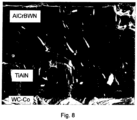
- Fig. 8 shows a scanning electron micrograph (SEM) of a cross section of a TiAlN/AlCrBWN double-layer hard coating system according to specimen 9 of Example 2.
- the IL 1 interlayer exhibits a columnar growth structure, with columns having a width in the order of 400 nm.
- the type HL 1 outer layer exhibits the same glassy-like growth structure as specimen No. 4 of Example 1 (see Fig. 7 ).
- the columnar growth structure is clearly interrupted at the interface between the interlayer and the outer layer.
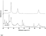
- Fig. 9 shows XRD spectra of an AlCrN single-layer hard coating system according to specimen No. 3 of Example No. 1 and of an AlCrBWN type HL 1 single-layer hard coating system according to specimen number 4 of Example 1.
- the XRD spectrum of AlCrN exhibits peaks at around 37.5°, 43.7° and 63.7°, which are assigned to the ⁇ 111>, ⁇ 200> and ⁇ 220> planes of an fcc-(face centered cubic)AlCrN crystal structure.
- Al x Cr 1-x N hard coating having an x ⁇ 0.7
- the AlCrBWN hard coating exhibits diffraction peaks which are assigned to the ⁇ 111>, ⁇ 200> and ⁇ 220> planes of AlCrN as well.
- Al x CrBWN hard coatings, having the same x of 0.7 show a remarkable contribution of hcp-(hexagonal closed packed) AlN. Peaks at around 33.1°, 49.5° and 58.9° point out signals attributed to that phase. Peaks at around 31.5°, 35.7°, 48.3°, 64.1° and 65.9° derive from the WC-Co body of the carbide substrate.
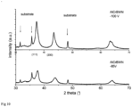
- Fig.10 shows XRD spectra of AlCrBWN hard coatings at workpieces according to the present invention.
- the upper spectrum refers to AlCrBWN coatings deposited under the deposition conditions of example 6 to 8.
- Lowering the substrate bias from -100 to -85 V against ground potential as shown in the lower spectrum of Fig 10 gives a remarkable change with respect to the Q value, however obviously induces a peak broadening. The latter can be referred to a further grain refinement.
Description
- The present invention is directed to a workpiece having a body and a wear-resistant hard coating system on at least a part of its surface, further to a method of manufacturing a device.
- TiAlN is a coating which is widely used to machine hardened steel and is customarily applied by a PVD process.
- We understand under a physical vapour deposition process (PVD) a vacuum deposition process, wherein a plasma is used and material is filled into the processing atmosphere from solid. Thereby, under this term of PVD e.g. cathodic arc evaporation, ion plating, sputtering, thereby magnetron sputtering, all the addressed processings reactive or nonreactive are members of the PVD processing category.
- In opposition thereto CVD coating processes, chemical vapour deposition, and PECVD, plasma enhanced chemical vapour deposition provide coating out of gaseous phase.
- TiAlN layers used as a single layer- or in multilayersystems with sublayers of different Ti/Al/N stochiometries, can be used up to working temperatures of 900°C at most for tooling application due to the incipient degradation of hardness at temperatures higher than 800 to 850°C depending on the Aluminum/Titanium ratio.
- Therefore, the
US 2005-0003239 proposes to apply AlCrN coatings to workpieces so as to increase their oxidation resistance. This coating is known to have a good oxidation resistance and a hot hardness up to 1100°C depending on the Aluminum/Chromium ratio. It is further referred to similar proposals in theWO 2006/005217 , theWO 2006/084404 and theUS 2006-0222893 trying to further improve oxidation resitance and/or hot hardness of the coatings by using different multilayers and/or by introducing other elements into the AlCrN matrix. - The
US 2006-0269789 discloses a hard multilayer to cut high hardness material at a high speed. The hard multilayer comprises a first TiAlCrNX-based layer, wherein X stands for C or O. A second layer consists of a mixture of TiAlCrNX and of TiAl(SiC)NX or is a multilayer of layers of these alternative materials. A third outermost layer essentially consists of TiAl(SiC)NX. - Another coating to improve cutting of hardened steels is disclosed in the
EP 1 690 959 . There the coating comprises a two-layer system based on (TiAlSi)N of different Al and Si stochiometries. Further prior art coatings are known inEP1219723 andWO2004/059030 . - In spite of the approaches as outlined above there is still a need to further improve hard coating systems on workpiece bodies with respect to wear and oxidation resistance, thereby further improving performance of such workpieces, especially used as cutting tools in machining of hard material, thereby especially of hardened steels.
- The invention concerns a workpiece according to claim 1 and a method according to
claim 11. - It is thus an object of the present invention to further improve hard coatings with respect to wear resistance and oxidation resistance. To resolve such object there is proposed a workpiece having a body and a wear resistant hard coating system on at least a part of the surface of the body, wherein the system comprises at least one layer of the following composition:
(Al1-a-b-cCraBbZc) X,
where - X is at least one of N, C, CN, NO, CO, CNO and
- Z is at least one of W, Mo, Ta, Cb (also referred to as Nb) and wherein there is valid


- Astonishingly, the addressed object is achieved by generically adding boron (B) and at least one of the addressed Z elements to a matrix of AlCrX type by fulfilling the addressed conditions with respect to stochiometry. We address this layer as HL0.
- In a preferred embodiment of the workpiece according to the invention the element Z is selected to be tungsten W and there is established


- We address this layer as HL1.
- We understand throughout the present description and claims under the term "coating system" or "coating subsystem" a system which consists of one single layer or of multiple, i.e. more than one layers.
- The addressed at least one layers HL0 possibly HL1 may thereby be applied directly on the surface of the workpiece body. They further may be applied to form the outermost layer of the coating system. Clearly, if such coating system consists of one layer, then the addressed layer of HL-type resides directly on the surface of the body and is the outermost layer. The layer of HL0-type may further be the outermost layer of a multilayer system. It further may be embedded within a multilayer system between a first layer subsystem towards the surface of the workpiece body and a second layer subsystem towards the surface of the coated body. Still further, in a multilayer system more than one of the addressed HLo-type layers of equal or of varying stochiometry and/or material composition may be provided. Thereby, such layers of HLo-type may reside directly one upon the other with different stochiometry and/or material composition or may be separated by respective coating layer subsystems.
- In one embodiment of the workpiece according to the present invention the at least one layer HL0 or HL1 resides outermost of the hard coating system.
- In one embodiment of the workpiece according to the present invention the at least one layer of HL0-type resides directly on the surface of the body of said workpiece.
- Still in a further embodiment the system comprises at least one interlayer of (TidAle)N. Thereby, in a further embodiment at least one of the addressed interlayers is interposed between the surface of the body and the addressed at least one HL0-type layer. We address this interlayer as IL1.
- In a further embodiment of the workpiece the addressed interlayer resides directly on at least one of the surface of the workpiece and of the at least one layer of HLo-type.
- Thus, in the embodiment wherein the interlayer is interposed between the surface of the body and the at least one HL0 or HL1, further interlayers of the addressed type may additionally be provided between the HL0 or HL1 and the surface of the system. Further, the addressed intermediate layer must not necessarily reside as the only layer between the surface of the body and the surface of the HL1 or HL0, additional layers may be provided therebetween, so that the interlayer is one layer of a multilayer subsystem between the surface of the body and HL0 or HL1. Nevertheless, in one embodiment the addressed intermediate coating directly resides upon at least one of the surface of the body and the HL0 or HL1. When applying the at least one interlayer of (TidAle)N in a further embodiment there is applied:


- In a further embodiment of the workpiece according to the present invention the hard coating system comprises at least one interlayer of (AlfCrg)N. We address this interlayer as IL2.
- With respect to where such at least one interlayer may be provided the same prevails as was addressed above with respect to the (TidAle)N layer - IL1 -, with the exception that for the (AlfCrg)N interlayer, in a further embodiment there is selected


- Further, both the addressed interlayers IL1 and IL2 may be provided in combination within the hard coating system.
- Still in a further embodiment of the workpiece according to the present invention, the at least one layer, HL0 or HL1, exhibits a relatively small fraction of AlN characterized by a crystal structure of the hexagonal type. Such hexagonal AlN phase in this embodiment resides with a percentage of Al of at least 70% within the metallic fraction of the HL0 or HL1 material, which fraction comprises all the elements but X of AlCrBZX or AlCrBWX.
- Such hexagonal structure may be recognized by XRD analysis.
- In a further embodiment of the workpiece according to the present invention the at least one HL0 or HL1 has a texture coefficient Q = I(200)/I(111) in the range of 0.1 ≤ Q ≤ 1. Such texture coefficient Q may be measured by X-ray diffraction analysis. As addressed, the term Q is defined as the ratio of the diffraction intensities I(200) to I(111) assigned respectively to the (200) and (111) planes in the X-ray diffraction of a material using a measuring setup as e.g. described in context with
fig. 4 of the present description. Thereby, in a further embodiment the addressed range of Q is even restricted to 0.1 ≤ Q ≤ 0.4. - Looking back to the addressed interlayers IL1, IL2 it should be mentioned that in respective embodiments these interlayers may exhibit a columnar growth structure, thereby giving to the overall coating system an excellent performance, especially if used on a cutting tool.
- In a further embodiment of the workpiece according to the present invention the hard coating system comprises a multilayer of alternating layers of at least one of the addressed interlayers IL1, IL2 and of at least one of HL0 and HL1, thereby preferably of (AlCrBW)X, i.e. HL1.
- Such a multilayer may e.g. comprise, departing from the surface of the body, a first of the addressed interlayers IL1, then possibly a second of the addressed interlayers IL2 of different type, then a first HL, i.e. HL0 or HL1, then again one or more than one of said interlayers IL1, IL2, a second HL0 or HL1 of same or of different material, a third HL0 or HL1 directly upon the former one, etc. etc. Thus, depending on the specific application there is a large variety of tailoring such multilayer hard coating system making use of the HL0 or HL1 and of the addressed intermediate layers IL1, IL2 in different combinations.
- In a further embodiment of the workpiece according to the invention the body is of high speed steel, hardened steel, cemented carbide or of cubic boron nitride or in a further embodiment of a cermet or of ceramic material.
- Still in a further embodiment the addressed workpiece according to the present invention is a cutting tool, thereby in a further embodiment an end mill, a drill, a cutting insert or a gear cutting tool.
- An exemplary process for manufacturing a workpiece as was addressed comprises providing such workpiece body in a plasma coating vacuum chamber, applying the hard coating system to the body by a physical vapour deposition process (PVD) during a processing time and thereby establishing a temperature of at least 550°C to the surface of the coated body during at least a predominant part of processing time.
- In one embodiment, not part of the invention, of such process the addressed temperature is selected to be at least 600°C.
- Still under a further aspect the present invention is directed on a method of manufacturing a device which has at least a part of a hard material. Such method comprises a cutting process of the hard material of the device using a cutting tool according to the present invention. Thereby, still in a further embodiment of the addressed device manufacturing method, the hard material has a Rockwell hardness of at least 52 HRC, thereby even of at least 55 HRC. Still in a further embodiment of the just addressed manufacturing method the hard material is hardened steel.
- Cutting processes have been performed with cutting tools according to the present invention which showed on hard material results at least as good or even better than comparative examples performed with state of the art tools. However, cutting operation on hardened steel or other high hardness materials having a Rockwell hardness of
HRC 50, especially of HRC 52 or higher, even of HRC higher than 55, the tools according to the present invention revealed a performance which was outstandingly good as will be shown below. - The present invention shall now be further described by means of examples and with the help of figures. The figures show:
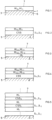
- Fig 1
- schematically a part of a first embodiment of a workpiece according to the present invention;
- Fig 2
- in a representation analogous to that of
fig 1 , a second embodiment of a workpiece according to the invention; - Fig 3
- in a representation analogous to those of
figs 1 and 2 a further embodiment of a workpiece according to the invention; - Fig 4
- in a representation analogous to those of
figs 1 to 3 a further embodiment of a workpiece according to the invention; - Fig 5
- in a representation analogous to those of
figs 1 to 4 a stil further embodiment of a workpiece according to the invention; - Fig 6
- a SEM of a cross-section of a AlCrN hard coating;
- Fig 7
- a SEM of a cross-section of a AlCrBWN hard coating at a workpiece according to the invention;
- Fig 8
- a SEM of a cross-section of a TiAlN/AlCrBWN hard coating at a workpiece according to the invention;
- Fig 9
- XRD spectra of an AlCrN and of an AlCrBWN hard coating, latter at a workpiece according to the invention;
- Fig 10
- XRD spectra of AlCrBWN hard coatings at workpieces according to the present invention.
- In
fig. 1 there is schematically shown a first embodiment of a workpiece 1 according to the present invention. The workpiece 1 has abody 3 with asurface 5. The body is of one of the materials high speed steel, hardened steel, cemented carbide, cubic boron nitride, cermet or of a ceramic material. - According to the embodiment of
fig. 1 one of the layers HLo which may be HL1 directly resides on thesurface 5 of thebody 3. - Thereby, the
surface 7 of the resulting workpiece is formed by one surface of the addressed layer HLo which thus, as a good embodiment, forms the outermost surface of the workpiece. - In the embodiment of
fig. 2 which is shown in a representation which is analogous to that offig. 1 there is provided a coating subsystem CSS between the addressed layer HLo which may be HL1 andsurface 5 of thebody 3. Such coating subsystem CSS may thereby according to the definition of coating subsystems as made above comprise one or more than one layers. - As may be seen in the definition of the layers HLo and also HL1 X, and in the case of HLo also Z may consist of different elements. According to the embodiment of
fig. 3 the outermost layer of the hard coating system is formed by HLo in a first material composition, denoted by HLo1 or by the layer HL1, in one specific material composition, denoted by HL11. Propagating towards thesubstrate 3 there is provided a second layer HL0 in a different material composition denoted by HL02 or respectively by HL1 in a different material composition, denoted by HL12. - There may or may not follow further layers of the HL0 type and/or of the HL1 type up to surface 5 of the
body 3. - Whereas at the embodiment of
fig. 3 the coating system consists of HL0x layers, at least a part thereof possibly HL1x layers, in the embodiment according tofig. 4 there is the hard coating system comprises a coating subsystem CSS. Such coating subsystem may or may not comprise further of the HLo-type layers, but does additionally comprise at least one layer which is not of the addressed HLo-type. - In all the embodiments of
fig. 1 to 4 the outermost layer with thesurface 7 is formed by a layer of the addressed HLo-type. This is a good approach to form the addressed outermost surface of the workpiece. - Nevertheless and e.g. with an eye on
fig. 4 for some appliances it might be advisable to provide (not shown) a further coating subsystem on top of the outermost HLo-type layer so that theoutermost surface 7 is formed by such outermost subsystem. - In the embodiment according to
fig. 5 layers of the HLotype alternate with coating subsystems CSS. Thereby, the alternatingly applied layers of HLo-type may be equal or different with respect to material composition. - The alternating coating subsystems again may consist of one or more than one layers, at least one thereof being not of the HLo-type.
- As exemplified by the embodiment according to
fig. 1 to 5 there exists a large variety to apply HLo layers to thebody 3 of the workpiece, in dependency of the specific needs for such workpiece. Especially if the workpiece is a tool, especially a cutting tool, it is suggested to select as the outermost layer of the coating system a HLo-type layer. - We have addressed in the introductory part of the description a first interlayer of (TidAle)N especially with d and e in specific ranges of values as IL1 and have addressed a second type of interlayer of (AlfCrg)N, with specific ranges for f and g as IL2.
- With an eye on the embodiments of
fig. 1 to 5 each of the addressed coating subsystems CSS may comprise or consist of IL1 or of IL2 or may comprise or consist of a combination of IL1 and IL2, and may comprise additional layers of the HLo-type or of layers different from HLo type and IL1, IL2. - Again, the skilled artisan recognizes from the addressed embodiments according to the
fig. 1 to 5 incorporating the interlayers IL1 and/or IL2 a larger variety of combinations selectable dependent on respective needs. - In the following some specific embodiments of the workpiece according to the present invention are exemplified. Cutting performance of workpieces according to the invention conceived as cutting tools were compared with such tools according to the state of the art, thereby equal cutting operations and cutting parameters were applied to the respective tools according to the present invention and to the comparative tools according to the state of the art, for valid comparison purpose.
- The hard coating systems applied to the specimens in the following examples were deposited under the following conditions, if not specifically and differently specified, whereby the process for manufacturing the workpieces according to a non inventive example was applied.
- Deposition technology: Cathodic arc evaporation
- Total working pressure: 5.5 Pa of N2
- Bias voltage of the body to be coated: -85V against ground potential for HL0 type layers and -100V against ground potential for IL1 and IL2 layers
- Surface temperature of body being coated: 600°C
- Evaporation current: 200 A per evaporation target
- The hard coating systems were deposited in a Balzers RCS coating machine in arc evaporation configuration. The cutting tool bodies were mounted on threefold rotating holders during the PVD deposition.
- All the hard coating systems deposited on the cutting tool body had a total thickness between 2 and 2.5 µm, measured on the shank of the cutting tool.
- A first series of mono-layered hard coating systems was compared with state of the art monolayer system of TiAlN and AlCrN.
- Table 1 displays the hard coating system investigated under this example. To apply each of the addressed monolayer hard coating systems the coating machine was equipped with four identical arc evaporation cathodes, also called targets. The respective compositions of these targets are also listed in table 1. The resulting composition of the coating material was within 10% of the target composition for the main elements Al, Cr, Ti and was within about 20% of the target composition for the element B and W, Mo and Ta.
Table 1 No. Hard coating Target composition 1com. TiAlN Ti0.5Al0.5 2com. TiAlN Ti0.33Al0.67 3com. AlCrN Al0.7Cr0.3 4 AlCrBWN Al0.7Cr0.226B0.067W0.007 5 AlCrBMoN Al0.7Cr0.21B0.07Mo0.02 6 AlCrBTaN Al0.7Cr0.226B0.067Ta0.007 - The performance of the hard coating systems was assessed in terms of wear resistance in a metal cutting operation. The amount of wear on the flank face, vbmax, was measured as a function of the length of the cut. The cutting test was a milling test under finishing conditions in a hardened cold work tool steel. The cutting conditions were the following:
Cutting tool: 2-fluted ball nose end mill, 5 mm ball radius, micro grain carbide grade material Workpiece: 1.2379 60 HRC Spindle rotation speed: 7996 rev/min Axial depth of cut: 0.4 mm Radial depth of cut: 0.2 mm Feed rate: 0.1 mm/tooth Cutting speed: 98 m/min Feed: 1600 mm/min Coolant: air Milling direction: down milling Length of 1 pass: 43.8 m End of tool life: vbmax > 0.15 mm at the end of a pass - The results of the cutting test are listed in Table 2.
Table 2 No. Cutting length (m) Amount of wear vbmax (mm) 1com. 87.6 0.25 2com. 87.6 0.17 3com. 87.6 0.2 4 131.4 0.25 5 131.4 0.33 6 131.4 0.41 - It can be seen that the incorporation of B and W, Mo and Ta in AlCrN results in an improved wear protection compared with the wear protection of AlCrN and TiAlN according to the comparative specimens 1 to 3.
- A series of double-layer hard coating systems was prepared. Table 3 lists the hard coating systems as investigated. The same tool bodies of the material as of Example 1 were coated. Thereby directly upon the surface of the tool body there was applied an interlayer IL1 and directly upon such interlayer a layer of HL1-type. The machine was equipped with two identical targets for the deposition of the interlayer and with four identical targets for the deposition of the outer layer of the HL1-type. The respective target material compositions are also listed in table 3.
Table 3 No. Hard coating Target composition Interlayer Outer layer Interlayer Outer layer 7com. TiAlN AlCrN Ti0.5Al0.5 Al0.7Cr0.3 8 TiAlN AlCrB WN Ti0.33Al0.67 Al0.7Cr0.226B0.067W0.007 9 TiAlN AlCrB WN Ti0.5Al0.5 Al0.7Cr0.226B0.067W0.007 - The performance of the tools according to this second series was investigated with the same cutting test as was applied to the example 1 tools. The results are listed in table 4.
- Thereby, the interlayer IL1 of specimen No. 9 shows a stochiometry which is well within the range of


Table 4 No. Cutting length (m) Amount of wear vbmax (mm) 7com. 87.6 0.4 8 267.8 0.18 9 438 0.15 - When applying a IL1 interlayer to the inventively provided HL-type layer especially tailored as HL1-type layer with X = N, provision of such interlayer most significantly improves wear resistance and even more if the addressed stochiometry ranges for the aluminum and titanium compounds are fulfilled.
- A further series of workpieces, namely tools with a hard coating system according to the present invention consisting of two layers, was prepared, namely consisting of an interlayer TiAlN, IL1 directly between a tool body as was already used in the examples 1 and 2 and a HL1-type layer with X = N as already provided in
specimens 8 and 9 of Table 3. Thereby, the temperature of a surface being coated was varied between 450°C and 600°C by varying heating time and/or power. - For the
specimens - Table 5 shows on one hand the addressed layers of the coating system and on the other hand the deposition temperatures.
Table 5 No. Hard coating Deposition temperature (°C) Interlayer Outer layer 10 TiAlN AlCrBWN 450 11 TiAlN AlCrBWN 550 12 TiAlN AlCrBWN 600 - The performance of the specimens was investigated with the same cutting conditions as Example 1. The results are listed in the following Table 6.
Table 6 No. Cutting length (m) Amount of wear vbmax (mm) 10 223 0.55 11 350.4 0.5 12 438 0.15 - The results show on one hand that specimen No. 12 which was coated identically to specimen No. 9 of example 2 exhibits equal wear resistance compared with the addressed
specimen 9. Further, specimen 10 reveals that even at lower temperatures of 450°C the coating system according to the present invention is significantly superior to a comparable two-layer coating system coated at 600°C as of specimen No. 7. - Further, it is evident from comparing the specimens 10 to 12 that wear resistance significantly increases with increasing deposition temperature and achieves best performance, as of specimen No. 12, at a maximum deposition temperature of 600°C as investigated or more.
- A fourth series of double-layered hard coating systems with an interlayer IL1 and a HL1-type layer of the specific embodiment with X = N was prepared.
- As comparison specimens prior art single layer systems of TiAlN and AlCrN were selected. The following Table 7 lists the respective coating material and the target composition.
Table 7 No. Hard coating Target composition 13com TiAlN Ti0.5Al0.5 14com AlCrN Al0.7Cr0.3 Interlayer Outer layer Interlayer Outer layer 15 TiAlN AlCrBWN Ti0.5Al0.5 Al0.7Cr0.226B0.067W0.007 - The performance of the resulting tools was assessed in terms of wear resistance in metal cutting application. The amount of wear on the flank face vbmax was measured in function of the length of the cut. The cutting tests were performed under the conditions of semi-finishing milling operation in a heat treated tool steel. The cutting conditions were the following:
Cutting tool: 3-fluted end mill, 8 mm diameter, micro grain carbide grade Workpiece: 1.2344 36 HRC Spindle rotation speed: 4775 rev/min Axial depth of cut: 10 mm Radial depth of cut: 0.5 mm Feed rate: 0.05 mm/tooth Cutting speed: 120 m/min Feed: 716 mm/min Coolant: 6% mineral oil based emulsion, external cooling Milling direction: down milling Length of 1 pass: 10 m End of tool life: vbmax > 0.15 mm at the end of a pass - Table 8 reveals the cutting test results.
Table 8 No. Cutting length (m) Amount of wear vbmax (mm) 13com. 30 0.17 14com. 80 0.17 15 100 0.18 - A series of tools with double-layer coating systems, namely consisting of an IL1 interlayer and a HL1-type layer with X = N was prepared. They were compared with respective tools coated with state of the art double-layer coating systems, namely of TiN as interlayer and TiAlN as outermost layer or coated with AlCrN as interlayer and a TiSiN as outermost layer.
- Table 9 shows the respective layer material and target material compositions.
Table 9 No. Hard coating Target composition Multilayer 16com TiN-TiAlN Ti - Ti0.5Al0.5 17com. AlCrN-TiSiN Al0.7Cr0.3 - Ti0. 85Si015 Double layer Interlayer Outer layer Interlayer Outer layer 18 TiAlN AlCrBWN Ti0.5Al0.5 Al0.7Cr0.226B0.067W0.007 - The performance of the respectively coated tools was assessed in drilling operation on heat treated steel. The amount of wear on the flank face of the main cutting edge vbmax was used to assess the wear protection quality. The test conditions were the following:
Cutting tool: 2-flute drill, 6.8 mm diameter, fine grain carbide grade Workpiece: 1.7225, Rm = 1000 N/mm2, annealed to a Brinell hardness of 240 HB Spindle rotation speed: 4684 rev/min Max. cutting speed: 100 m/min Feed rate: 0.18 mm/rev Feed: 843 mm/min Hole depth: 34 mm Coolant: 6% mineral oil based emulsion, external cooling End of tool life: vbmax > 0.2 mm - The following table 10 displays the drilling results.
Table 10 No. Number of holes Amount of wear vbmax (mm) 16com. 2128 0.2 17com. 2432 0.18 18 912 0.25 - This example makes clear that the tools according to the present invention may not be the best choice for use in highly annealed steels and soft materials.
- In the following examples No. 6 to 8 the hard coating systems were deposited again as was already addressed for the previous examples, but the total working pressure N2 was reduced from 5.5 Pa to 3.5 Pa and the substrate bias voltage against ground was increased from -85 V to -100 V for the deposition of the AlCrBWN outermost layer according to HL1 with X = N.
- A sixth series of tools was prepared to establish the effect of an AlCrN interlayer IL2 instead of a TiAlN - interlayer IL1.
- The Table 11 shows the respective layer materials and the target compositions.
Table 11: No. Hard coating Target composition Double layer Interlayer Outer layer Inter layer Outer layer 19 TiAlN AlCrBWN Ti0.5Al0.5 Al0.7Cr0.226B0.067W0.007 20 AlCrN AlCrBWN Ti0.5Al0.5 Al0.7Cr0.226B0.067W0.007 - Using tools coated as addressed, a cutting test with the following parameters was applied
Cutting tool: 2-fluted ball nose end mill, 5 mm ball radius, micro grain carbide grade material Workpiece: 1.2379 60 HRC Spindle rotation speed: 6370 rev/min Axial depth of cut: 0.3 mm Radial depth of cut: 0.5 mm Feed rate: 0.15 mm/tooth Cutting speed: 200 m/min Feed: 1911 mm/min Coolant: air Milling direction: down milling Length of 1 pass: 30 m End of tool life: vbmax > 0.10 mm at the end of a pass - The results are shown in Table 12.
Table 12 No. Cutting length (m) Amount of wear vbmax (mm) 19 270 0.11 20 240 0.12 - From these results it may be seen that providing a IL1 or a IL2 interlayer leads substantially to the same good results.
- By the seventh series of specimens it was the aim to establish for the effect of a different B and W content at a HL1-type layer with X = N. The following Table 13 lists the material of the interlayer as well as of the outer layer and the respective compositions of the target materials.
Table 13: No. Hard coating Target composition Double layer Interlayer Outer layer Interlayer Outer layer 21com. TiAlN AlCrN Ti0.5Al0.5 Al0.7Cr0.3 22 TiAlN AlCrBWN Ti0.5Al0.5 Al0.7Cr0.226B0.067W0.007 23com. TiAlN AlCrWN Ti0.5Al0.5 Al0.7Cr0.28W0.02 - Using such tools, a cutting test with the same parameters as in example 6 was applied
- The results are shown in Table 14
Table 14 No. Cutting length (m) Amount of wear vbmax (mm) 21com. 120 0.11 22 240 0.10 23com. 150 0.11 - In the eighth series of specimens which were coated with a two-layer coating system as addressed in Table 15, prior to the cutting tests a brushing treatment was applied using a brushing machine according to the
DE GM 20 2006 000 654.1 in order to adjust a state comparable to an initial homogeneous wear, which ensures afterwards a homogeneous progress of the wear during the cutting application. - The treatment of the coated tool was conducted with rotary brushes according to the addressed document.
Fig. 2 and the respective description onpage 5, last para., until page 6, end of the first para. of thisGerman Utilty Model No. 20 2006 000 654.1 is specifically included and referred to by reference in the present description with respect to the addressed brushing technique. The brush angle was about 30° with reference to the tool axis, rotation speed selected to 650 turns/minute. Brushing material was SiC impregnated Nylon, SiC grain size 400 mesh, diameter of bristles 0.45mm, length of bristles 35mm. Rotation of the tool satellite was 9 turns/min, rotation of the table supporting the satellites was about 0.3 turns/min. A similar effect to dissect a few micrometers' stripe of the workpiece material along the cutting edge could have been achieved by using Al2O3 impregnated brushes. Nevertheless, for this latter brushing, time has to be tripled if the same parameters as mentioned above are used. This may be realized e.g. by rotation of the supporting table by 0.1 turns/min. - Alternatively or even additionally a similar honing treatment by brush, blast, grinding operations or the like can be applied before the coating process as a pretreatment.
- With the tool coated according to Table 15
Table 15 No. Hard coating Target composition Double layer Interlayer Outer layer Interlayer Outer layer 24 TiAlN AlCrBWN Ti0.5Al0.5 Al0.7Cr0.226B0.067W0.007 Cutting tool: 2-fluted ball nose end mill, 5 mm ball radius, micro grain carbide grade material Workpiece: 1.2379 62 HRC Spindle rotation speed: 6000 rev/min Axial depth of cut: 0.4 mm Radial depth of cut: 0.05 mm Feed rate: 0.10 mm/tooth Cutting speed: 184 m/min Feed: 600 mm/min Coolant: air Milling direction: down milling technique for pockets (56 mm x 26 mm) Length of single pass: 1 pocket End of toollife: vbmax > 0.10 mm at the end of a pocket Table 16 No. Brushing treatment (yes/no) Number of pockets (N) 24a No 4 24b Yes 10 - From the examples as shown above it becomes clear that tools wherein the hard coating systems comprise the HL0 layer in the specific form of HL1 with X = N as in a single layer system or, and especially in connection with the addressed IL1 and/or IL2 interlayer, provide for an astonishing increase of wear resistance compared with state of the art coating systems e.g. with outermost TiAlN or AlCrN coating systems.
- Despite the fact that the addressed HL1 with X = N coating is applied through all the examples as the outermost layer of the coating system, it is evident to the skilled artisan that for some applications additional layers may be provided upon the addressed layer as e.g. a lubricating layer.
- Further, throughout the examples the addressed HL1 layer is, considered towards the tool body, applied either directly on the tool body or separate there from by a IL1 or IL2 interlayer.
- Nevertheless, for some applications it is evident to the skilled artisan that such multilayer systems with the inventively proposed HL-type and IL-type layers may be conceived in a huge variety depending upon the specific needs.
- Moreover, the above examples have been conducted specifically on the HL1 layers, wherein X = N. Nevertheless, it is perfectly clear to the skilled artisan that replacing N by C, CN, NO, CO or CNO will lead to layers HL1 with similar wear resistance qualities.
- The same is valid if in the HL1 type layer the element W is replaced by Mo, Ta, Cb (Nb).
- Still further, the tools whereupon the examples have been performed have a tool body of tungsten carbide.
- Nevertheless, with respect to the material of the tool body or more generic workpiece body, it is perfectly clear to the skilled artisan that the targeted increase of wear resistance by the coating system according to the present invention will also be achieved on workpiece bodies of high speed steel, cemented carbide or cubic boron nitride or of a cermet or of a ceramic material. The addressed improvement of wear resistance may be highly desirable not only for tools like cutting tools such as for end mills, drills, cutting inserts, gear cutting tools but also for other workpieces than tools.
- By the method of manufacturing a device which is at least in part of a hard material, thereby especially with a hardness of at least HRC 52, comprising a cutting process of the addressed hard material using the cutting tool according to the present invention, device manufacturing becomes faster, thus throughput higher and manufacturing costs are lowered.
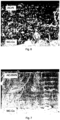
- In
fig. 6 there is shown a SEM cross-section of a AlCrN coating. This accords with a scanning electron micrograph (SEM) of a cross-section of the single layer hard coating system according tospecimen 3 of example No. 1. The hard coating exhibits a very fine columnar growth structure with columns having a width in the order of 200 nm. -
Fig. 7 shows such scanning electron micrograph of a cross-section of the AlCrBWN single layer hard coating system according to specimen No. 4 of example 1. This hard coating exhibits no columnar growth structure. The strong renucleation process during deposition leads to a nanocrystalline coating structure which appears glassy like in the SEM cross-section under a magnification of 25'000. -
Fig. 8 shows a scanning electron micrograph (SEM) of a cross section of a TiAlN/AlCrBWN double-layer hard coating system according tospecimen 9 of Example 2. The IL1 interlayer exhibits a columnar growth structure, with columns having a width in the order of 400 nm. - The type HL1 outer layer exhibits the same glassy-like growth structure as specimen No. 4 of Example 1 (see
Fig. 7 ). The columnar growth structure is clearly interrupted at the interface between the interlayer and the outer layer. -
Fig. 9 shows XRD spectra of an AlCrN single-layer hard coating system according to specimen No. 3 of Example No. 1 and of an AlCrBWN type HL1 single-layer hard coating system according to specimen number 4 of Example 1. The spectra were recorded with a Bruker AXS equipment, using a Cuκα incident beam (λ = a 1.5406nm) and a glancing incidence angle of 2° which delivers an appreciable quality for the spectra of nano-crystalline coatings. This configuration allows to measure even thin films without disturbing influence by the substrate and/or by an interlayer. The XRD spectrum of AlCrN exhibits peaks at around 37.5°, 43.7° and 63.7°, which are assigned to the <111>, <200> and <220> planes of an fcc-(face centered cubic)AlCrN crystal structure. - As expected for an AlxCr1-xN hard coating having an x ≤ 0.7, there is no hexagonal AlN phase in such hard coating. The AlCrBWN hard coating exhibits diffraction peaks which are assigned to the <111>, <200> and <220> planes of AlCrN as well. However AlxCrBWN hard coatings, having the same x of 0.7, show a remarkable contribution of hcp-(hexagonal closed packed) AlN. Peaks at around 33.1°, 49.5° and 58.9° point out signals attributed to that phase. Peaks at around 31.5°, 35.7°, 48.3°, 64.1° and 65.9° derive from the WC-Co body of the carbide substrate.
-
Fig.10 shows XRD spectra of AlCrBWN hard coatings at workpieces according to the present invention. - Measurement was performed using the setup as was described in context with
Figure 9 . The upper spectrum refers to AlCrBWN coatings deposited under the deposition conditions of example 6 to 8. Lowering the substrate bias from -100 to -85 V against ground potential as shown in the lower spectrum ofFig 10 gives a remarkable change with respect to the Q value, however obviously induces a peak broadening. The latter can be referred to a further grain refinement.
Claims (11)
- A workpiece having a body and a wear resistant hard coating system on at least a part of the surface of said body, said system comprising at least one layer of the following composition
(Al1-a-b-c Cra Bb Zc) X
whereX is at least one of: N, CN, NO, CNO;Z is at least one of: W, Mo, Ta, Nb;wherein there is valid


- The workpiece of claim 1, wherein said system comprises at least one interlayer of (TidAle)N
, wherein there is valid:

- The workpiece of one of claims 1 to 2, wherein said system comprises at least one interlayer of (AlfCrg)N
, wherein there is valid

- The workpiece of one of claims 1 to 3, wherein said at least one layer comprises hexagonal AlN.
- The workpiece of one of claims 1 to 4, wherein said at least one layer has a texture coefficient Q = I(200)/I(111) in the range of 0.1 ≤ Q ≤ 1.
- The workpiece according to one of the claims 2 to 5, wherein said TiAlN or AlCrN interlayer respectively exhibits a columnar growth structure.
- The workpiece of one of claims 1 to 6, wherein said system comprises a multilayer of alternating layer of at least one of (TidAle)N and of (AlfCrg)N and of said at least one layer, preferably of (Al1-a-b Cra Bb Wc)X.
- The workpiece of one of claims 1 to 7, said body being of one of high-speed steel, hardened steel, cemented carbide and of cubic boron nitride.
- The workpiece of one of the claims 1 to 8, said body being of one of a cermet and of a ceramic material.
- The workpiece of claim 8 or 9 being one of an end mill, a drill, a cutting insert, a gear cutting tool.
- A method of manufacturing a device at least in part of a hard material comprising a cutting process of said hard material using a workpiece according to claim 8 or 9 being a cutting tool.
Applications Claiming Priority (3)
| Application Number | Priority Date | Filing Date | Title |
|---|---|---|---|
| US82694306P | 2006-09-26 | 2006-09-26 | |
| US90955907P | 2007-04-02 | 2007-04-02 | |
| PCT/EP2007/059070 WO2008037556A2 (en) | 2006-09-26 | 2007-08-30 | Workpiece with hard coating |
Publications (2)
| Publication Number | Publication Date |
|---|---|
| EP2069553A2 EP2069553A2 (en) | 2009-06-17 |
| EP2069553B1 true EP2069553B1 (en) | 2023-03-08 |
Family
ID=39230563
Family Applications (1)
| Application Number | Title | Priority Date | Filing Date |
|---|---|---|---|
| EP07803079.8A Active EP2069553B1 (en) | 2006-09-26 | 2007-08-30 | Workpiece with hard coating |
Country Status (17)
| Country | Link |
|---|---|
| US (2) | US8211554B2 (en) |
| EP (1) | EP2069553B1 (en) |
| JP (1) | JP5593069B2 (en) |
| KR (1) | KR101432847B1 (en) |
| CN (1) | CN104805436A (en) |
| AU (1) | AU2007302162B2 (en) |
| BR (1) | BRPI0717566B1 (en) |
| CA (1) | CA2662537C (en) |
| ES (1) | ES2945897T3 (en) |
| IL (1) | IL197787A (en) |
| MX (1) | MX2009003288A (en) |
| MY (1) | MY149446A (en) |
| NZ (1) | NZ575279A (en) |
| PL (1) | PL2069553T3 (en) |
| RU (1) | RU2469128C2 (en) |
| TW (1) | TWI422710B (en) |
| WO (1) | WO2008037556A2 (en) |
Families Citing this family (27)
| Publication number | Priority date | Publication date | Assignee | Title |
|---|---|---|---|---|
| PT2310549T (en) * | 2008-07-09 | 2018-02-08 | Oerlikon Surface Solutions Ltd Pfaeffikon | Coating system, coated workpiece and method for manufacturing the same |
| CN102459688B (en) * | 2009-06-18 | 2014-06-11 | 苏舍梅塔普拉斯有限责任公司 | Protective coating, a coated member having a protective coating as well as method for producing a protective coating |
| US8277958B2 (en) | 2009-10-02 | 2012-10-02 | Kennametal Inc. | Aluminum titanium nitride coating and method of making same |
| JP4753144B2 (en) * | 2009-12-21 | 2011-08-24 | 住友電工ハードメタル株式会社 | Surface coated cutting tool |
| JP4753143B2 (en) * | 2009-12-21 | 2011-08-24 | 住友電工ハードメタル株式会社 | Surface coated cutting tool |
| RU2560480C2 (en) * | 2010-02-04 | 2015-08-20 | Эрликон Трейдинг Аг, Трюббах | CUTTING TOOLS WITH SANDWICHED COATINGS OF Al-Cr-B/Ti-Al-N |
| US8409702B2 (en) | 2011-02-07 | 2013-04-02 | Kennametal Inc. | Cubic aluminum titanium nitride coating and method of making same |
| SG11201401080RA (en) * | 2011-09-30 | 2014-04-28 | Oerlikon Trading Ag Trübbach | Aluminum titanium nitride coating with adapted morphology for enhanced wear resistance in machining operations and method thereof |
| CN104508171B (en) * | 2012-04-16 | 2016-10-19 | 欧瑞康表面解决方案股份公司,普费菲孔 | Coat system, the matrix of coating and the method with coat system coating matrix surface |
| US9103036B2 (en) | 2013-03-15 | 2015-08-11 | Kennametal Inc. | Hard coatings comprising cubic phase forming compositions |
| BR112015026236A2 (en) * | 2013-04-22 | 2017-07-25 | The Gleason Works | trimming of cylindrical gears |
| EP3006601B1 (en) * | 2013-05-30 | 2019-12-11 | Hitachi Metals, Ltd. | Method for manufacturing mold for cold working use |
| JP5663814B2 (en) * | 2013-07-03 | 2015-02-04 | 住友電工ハードメタル株式会社 | Surface coated boron nitride sintered body tool |
| US9168664B2 (en) | 2013-08-16 | 2015-10-27 | Kennametal Inc. | Low stress hard coatings and applications thereof |
| US9896767B2 (en) | 2013-08-16 | 2018-02-20 | Kennametal Inc | Low stress hard coatings and applications thereof |
| DE102013018867A1 (en) * | 2013-11-12 | 2015-06-25 | Oerlikon Trading Ag, Trübbach | (Al, Cr, Ta) N-coating for improved temperature resistance |
| DE102013018007A1 (en) * | 2013-11-29 | 2015-06-03 | Oerlikon Trading Ag, Trübbach | Method for improving the Gegenkörperverschleisses in tribological contact |
| CA3007278A1 (en) * | 2015-12-07 | 2017-06-15 | Ihi Ionbond Ag | Coated extrusion tool |
| EP3394312B1 (en) * | 2015-12-22 | 2020-06-17 | Sandvik Intellectual Property AB | A coated cutting tool and method |
| KR102614205B1 (en) | 2016-06-02 | 2023-12-14 | 다나카 기킨조쿠 고교 가부시키가이샤 | Gold sputtering target |
| RU2639425C1 (en) * | 2016-12-20 | 2017-12-21 | федеральное государственное бюджетное образовательное учреждение высшего образования "Ульяновский государственный технический университет" | Method of producing multi-layer coating for cutting tool |
| US10570501B2 (en) | 2017-05-31 | 2020-02-25 | Kennametal Inc. | Multilayer nitride hard coatings |
| KR102571881B1 (en) * | 2017-11-16 | 2023-08-28 | 가부시키가이샤 몰디노 | Coated Cutting Tool, Manufacturing Method and Chemical Vapor Deposition Apparatus |
| JP6927431B2 (en) * | 2018-05-30 | 2021-09-01 | 株式会社Moldino | Cover cutting tool and its manufacturing method |
| US11630435B2 (en) * | 2018-10-12 | 2023-04-18 | Tata Consultancy Services Limited | Method and system for monitoring tool wear to estimate RUL of tool in machining |
| KR102646471B1 (en) | 2019-05-09 | 2024-03-11 | 가부시키가이샤 몰디노 | covered cutting tools |
| US11731202B2 (en) | 2021-04-19 | 2023-08-22 | Kennametal Inc. | Coating, method for coating, and coated cutting tool |
Family Cites Families (14)
| Publication number | Priority date | Publication date | Assignee | Title |
|---|---|---|---|---|
| SE520802C2 (en) * | 1997-11-06 | 2003-08-26 | Sandvik Ab | Cutting tool coated with alumina and process for its manufacture |
| SE516622C2 (en) * | 2000-06-15 | 2002-02-05 | Uddeholm Tooling Ab | Steel alloy, plastic forming tool and toughened plastic forming tool |
| DE60124061T2 (en) * | 2000-12-28 | 2007-04-12 | Kabushiki Kaisha Kobe Seiko Sho, Kobe | Hard material layer for cutting tools |
| JP3971337B2 (en) * | 2003-04-30 | 2007-09-05 | 株式会社神戸製鋼所 | Method for producing alumina film mainly composed of α-type crystal structure, member coated with alumina film mainly composed of α-type crystal structure, and method for producing the same |
| BRPI0409913B1 (en) * | 2003-04-28 | 2015-08-04 | Oerlikon Trading Ag Trübbach | Workpiece coated with Alcr layer and process for coating such part. |
| US7226670B2 (en) | 2003-04-28 | 2007-06-05 | Oc Oerlikon Balzers Ag | Work piece with a hard film of AlCr-containing material, and process for its production |
| CN101048528B (en) * | 2004-07-15 | 2010-06-02 | 奥尔利康贸易股份公司(特吕巴赫) | High oxidation resistant hard coating for cutting tools |
| JP2006082207A (en) * | 2004-09-17 | 2006-03-30 | Sumitomo Electric Hardmetal Corp | Surface coated cutting tool |
| JP5060714B2 (en) * | 2004-09-30 | 2012-10-31 | 株式会社神戸製鋼所 | Hard coating excellent in wear resistance and oxidation resistance, and target for forming the hard coating |
| JP2006188736A (en) * | 2005-01-07 | 2006-07-20 | Nissin Electric Co Ltd | Article coated with abrasion resistant film |
| JP5143571B2 (en) * | 2005-02-10 | 2013-02-13 | エーリコン・トレイディング・アーゲー・トリューバッハ | High wear resistant triple coating for cutting tools |
| JP4702520B2 (en) | 2005-02-14 | 2011-06-15 | 三菱マテリアル株式会社 | Cutting tool made of surface-coated cemented carbide that provides excellent wear resistance with a hard coating layer in high-speed cutting of hardened steel |
| US7348074B2 (en) | 2005-04-01 | 2008-03-25 | Oc Oerlikon Balzers Ag | Multilayer hard coating for tools |
| JP4672442B2 (en) | 2005-05-31 | 2011-04-20 | オーエスジー株式会社 | Hard laminate coating and hard laminate coating tool |
-
2007
- 2007-08-30 WO PCT/EP2007/059070 patent/WO2008037556A2/en active Application Filing
- 2007-08-30 RU RU2009115694/02A patent/RU2469128C2/en not_active IP Right Cessation
- 2007-08-30 MY MYPI20091207A patent/MY149446A/en unknown
- 2007-08-30 AU AU2007302162A patent/AU2007302162B2/en not_active Ceased
- 2007-08-30 KR KR1020097007291A patent/KR101432847B1/en active IP Right Grant
- 2007-08-30 EP EP07803079.8A patent/EP2069553B1/en active Active
- 2007-08-30 JP JP2009529642A patent/JP5593069B2/en active Active
- 2007-08-30 CN CN201510137998.4A patent/CN104805436A/en active Pending
- 2007-08-30 PL PL07803079.8T patent/PL2069553T3/en unknown
- 2007-08-30 ES ES07803079T patent/ES2945897T3/en active Active
- 2007-08-30 NZ NZ575279A patent/NZ575279A/en not_active IP Right Cessation
- 2007-08-30 MX MX2009003288A patent/MX2009003288A/en active IP Right Grant
- 2007-08-30 BR BRPI0717566A patent/BRPI0717566B1/en not_active IP Right Cessation
- 2007-08-30 CA CA 2662537 patent/CA2662537C/en not_active Expired - Fee Related
- 2007-09-20 US US11/858,362 patent/US8211554B2/en active Active
- 2007-09-26 TW TW96135691A patent/TWI422710B/en not_active IP Right Cessation
-
2009
- 2009-03-24 IL IL19778709A patent/IL197787A/en active IP Right Grant
-
2012
- 2012-05-31 US US13/484,384 patent/US8329000B2/en active Active
Also Published As
| Publication number | Publication date |
|---|---|
| US8211554B2 (en) | 2012-07-03 |
| BRPI0717566B1 (en) | 2019-01-22 |
| RU2469128C2 (en) | 2012-12-10 |
| TW200831706A (en) | 2008-08-01 |
| IL197787A (en) | 2013-09-30 |
| KR20090063250A (en) | 2009-06-17 |
| US20100263503A1 (en) | 2010-10-21 |
| AU2007302162B2 (en) | 2012-06-28 |
| MX2009003288A (en) | 2009-06-30 |
| TWI422710B (en) | 2014-01-11 |
| MY149446A (en) | 2013-08-30 |
| AU2007302162A1 (en) | 2008-04-03 |
| NZ575279A (en) | 2012-05-25 |
| KR101432847B1 (en) | 2014-08-26 |
| CA2662537A1 (en) | 2008-04-03 |
| JP2010504439A (en) | 2010-02-12 |
| RU2009115694A (en) | 2010-11-10 |
| CA2662537C (en) | 2015-01-20 |
| EP2069553A2 (en) | 2009-06-17 |
| WO2008037556A3 (en) | 2008-12-11 |
| JP5593069B2 (en) | 2014-09-17 |
| WO2008037556A2 (en) | 2008-04-03 |
| BRPI0717566A2 (en) | 2013-12-03 |
| IL197787A0 (en) | 2009-12-24 |
| ES2945897T3 (en) | 2023-07-10 |
| CN104805436A (en) | 2015-07-29 |
| US8329000B2 (en) | 2012-12-11 |
| PL2069553T3 (en) | 2023-07-31 |
| US20120234143A1 (en) | 2012-09-20 |
Similar Documents
| Publication | Publication Date | Title |
|---|---|---|
| EP2069553B1 (en) | Workpiece with hard coating | |
| EP1722009B1 (en) | Thin wear resistant coating | |
| EP2643498B1 (en) | Coated cutting tool insert for metal machining that generates high temperatures | |
| EP1347076B1 (en) | PVD-Coated cutting tool insert | |
| JP6677932B2 (en) | Surface coated cutting tool that demonstrates excellent chipping and wear resistance in heavy interrupted cutting | |
| US8409695B2 (en) | Multilayer nitride hard coatings | |
| EP1485520B2 (en) | Nanolayered coated cutting tool | |
| EP1939328B1 (en) | Multilayered coated cutting tool | |
| EP2064363B1 (en) | Coated drill and a method of making the same | |
| EP1726390B1 (en) | Surface-coated cutting tool | |
| EP2576854B1 (en) | Coated cutting tool | |
| US20080299366A1 (en) | Cemented carbide insert | |
| US20070160843A1 (en) | Coated cemented carbide inserts | |
| KR20090028444A (en) | Coated cutting insert for milling applications | |
| JP7415223B2 (en) | A surface-coated cutting tool that exhibits excellent chipping and wear resistance during heavy interrupted cutting. | |
| CN101517126A (en) | Workpiece with hard coating | |
| EP4198169A1 (en) | Cutting tool |
Legal Events
| Date | Code | Title | Description |
|---|---|---|---|
| PUAI | Public reference made under article 153(3) epc to a published international application that has entered the european phase |
Free format text: ORIGINAL CODE: 0009012 |
|
| 17P | Request for examination filed |
Effective date: 20090320 |
|
| AK | Designated contracting states |
Kind code of ref document: A2 Designated state(s): AT BE BG CH CY CZ DE DK EE ES FI FR GB GR HU IE IS IT LI LT LU LV MC MT NL PL PT RO SE SI SK TR |
|
| AX | Request for extension of the european patent |
Extension state: AL BA HR MK RS |
|
| DAX | Request for extension of the european patent (deleted) | ||
| 17Q | First examination report despatched |
Effective date: 20121019 |
|
| STAA | Information on the status of an ep patent application or granted ep patent |
Free format text: STATUS: EXAMINATION IS IN PROGRESS |
|
| STAA | Information on the status of an ep patent application or granted ep patent |
Free format text: STATUS: EXAMINATION IS IN PROGRESS |
|
| STAA | Information on the status of an ep patent application or granted ep patent |
Free format text: STATUS: EXAMINATION IS IN PROGRESS |
|
| REG | Reference to a national code |
Ref country code: DE Ref legal event code: R079 Ref document number: 602007061639 Country of ref document: DE Free format text: PREVIOUS MAIN CLASS: C23C0030000000 Ipc: C08J0007120000 Ref country code: DE Ref legal event code: R079 Free format text: PREVIOUS MAIN CLASS: C23C0030000000 Ipc: C08J0007120000 |
|
| RIC1 | Information provided on ipc code assigned before grant |
Ipc: C23C 28/00 20060101ALI20220214BHEP Ipc: C08J 7/046 20200101ALI20220214BHEP Ipc: C08J 7/04 20060101ALI20220214BHEP Ipc: C23C 28/04 20060101ALI20220214BHEP Ipc: C23C 30/00 20060101ALI20220214BHEP Ipc: C23C 14/32 20060101ALI20220214BHEP Ipc: C23C 14/06 20060101ALI20220214BHEP Ipc: C08J 7/12 20060101AFI20220214BHEP |
|
| GRAP | Despatch of communication of intention to grant a patent |
Free format text: ORIGINAL CODE: EPIDOSNIGR1 |
|
| STAA | Information on the status of an ep patent application or granted ep patent |
Free format text: STATUS: GRANT OF PATENT IS INTENDED |
|
| INTG | Intention to grant announced |
Effective date: 20220922 |
|
| GRAS | Grant fee paid |
Free format text: ORIGINAL CODE: EPIDOSNIGR3 |
|
| GRAA | (expected) grant |
Free format text: ORIGINAL CODE: 0009210 |
|
| STAA | Information on the status of an ep patent application or granted ep patent |
Free format text: STATUS: THE PATENT HAS BEEN GRANTED |
|
| RAP3 | Party data changed (applicant data changed or rights of an application transferred) |
Owner name: OERLIKON SURFACE SOLUTIONS AG, PFAEFFIKON |
|
| AK | Designated contracting states |
Kind code of ref document: B1 Designated state(s): AT BE BG CH CY CZ DE DK EE ES FI FR GB GR HU IE IS IT LI LT LU LV MC MT NL PL PT RO SE SI SK TR |
|
| REG | Reference to a national code |
Ref country code: GB Ref legal event code: FG4D |
|
| REG | Reference to a national code |
Ref country code: CH Ref legal event code: EP Ref country code: AT Ref legal event code: REF Ref document number: 1552563 Country of ref document: AT Kind code of ref document: T Effective date: 20230315 |
|
| REG | Reference to a national code |
Ref country code: DE Ref legal event code: R096 Ref document number: 602007061639 Country of ref document: DE |
|
| REG | Reference to a national code |
Ref country code: IE Ref legal event code: FG4D |
|
| REG | Reference to a national code |
Ref country code: LT Ref legal event code: MG9D |
|
| REG | Reference to a national code |
Ref country code: ES Ref legal event code: FG2A Ref document number: 2945897 Country of ref document: ES Kind code of ref document: T3 Effective date: 20230710 |
|
| PG25 | Lapsed in a contracting state [announced via postgrant information from national office to epo] |
Ref country code: LV Free format text: LAPSE BECAUSE OF FAILURE TO SUBMIT A TRANSLATION OF THE DESCRIPTION OR TO PAY THE FEE WITHIN THE PRESCRIBED TIME-LIMIT Effective date: 20230308 Ref country code: LT Free format text: LAPSE BECAUSE OF FAILURE TO SUBMIT A TRANSLATION OF THE DESCRIPTION OR TO PAY THE FEE WITHIN THE PRESCRIBED TIME-LIMIT Effective date: 20230308 |
|
| REG | Reference to a national code |
Ref country code: AT Ref legal event code: MK05 Ref document number: 1552563 Country of ref document: AT Kind code of ref document: T Effective date: 20230308 |
|
| PG25 | Lapsed in a contracting state [announced via postgrant information from national office to epo] |
Ref country code: SE Free format text: LAPSE BECAUSE OF FAILURE TO SUBMIT A TRANSLATION OF THE DESCRIPTION OR TO PAY THE FEE WITHIN THE PRESCRIBED TIME-LIMIT Effective date: 20230308 Ref country code: NL Free format text: LAPSE BECAUSE OF FAILURE TO SUBMIT A TRANSLATION OF THE DESCRIPTION OR TO PAY THE FEE WITHIN THE PRESCRIBED TIME-LIMIT Effective date: 20230308 Ref country code: GR Free format text: LAPSE BECAUSE OF FAILURE TO SUBMIT A TRANSLATION OF THE DESCRIPTION OR TO PAY THE FEE WITHIN THE PRESCRIBED TIME-LIMIT Effective date: 20230609 Ref country code: FI Free format text: LAPSE BECAUSE OF FAILURE TO SUBMIT A TRANSLATION OF THE DESCRIPTION OR TO PAY THE FEE WITHIN THE PRESCRIBED TIME-LIMIT Effective date: 20230308 |
|
| PG25 | Lapsed in a contracting state [announced via postgrant information from national office to epo] |
Ref country code: RO Free format text: LAPSE BECAUSE OF FAILURE TO SUBMIT A TRANSLATION OF THE DESCRIPTION OR TO PAY THE FEE WITHIN THE PRESCRIBED TIME-LIMIT Effective date: 20230308 Ref country code: PT Free format text: LAPSE BECAUSE OF FAILURE TO SUBMIT A TRANSLATION OF THE DESCRIPTION OR TO PAY THE FEE WITHIN THE PRESCRIBED TIME-LIMIT Effective date: 20230710 Ref country code: EE Free format text: LAPSE BECAUSE OF FAILURE TO SUBMIT A TRANSLATION OF THE DESCRIPTION OR TO PAY THE FEE WITHIN THE PRESCRIBED TIME-LIMIT Effective date: 20230308 Ref country code: CZ Free format text: LAPSE BECAUSE OF FAILURE TO SUBMIT A TRANSLATION OF THE DESCRIPTION OR TO PAY THE FEE WITHIN THE PRESCRIBED TIME-LIMIT Effective date: 20230308 Ref country code: AT Free format text: LAPSE BECAUSE OF FAILURE TO SUBMIT A TRANSLATION OF THE DESCRIPTION OR TO PAY THE FEE WITHIN THE PRESCRIBED TIME-LIMIT Effective date: 20230308 |
|
| PGFP | Annual fee paid to national office [announced via postgrant information from national office to epo] |
Ref country code: IT Payment date: 20230822 Year of fee payment: 17 Ref country code: GB Payment date: 20230822 Year of fee payment: 17 Ref country code: ES Payment date: 20230914 Year of fee payment: 17 Ref country code: CH Payment date: 20230902 Year of fee payment: 17 |
|
| PG25 | Lapsed in a contracting state [announced via postgrant information from national office to epo] |
Ref country code: SK Free format text: LAPSE BECAUSE OF FAILURE TO SUBMIT A TRANSLATION OF THE DESCRIPTION OR TO PAY THE FEE WITHIN THE PRESCRIBED TIME-LIMIT Effective date: 20230308 Ref country code: IS Free format text: LAPSE BECAUSE OF FAILURE TO SUBMIT A TRANSLATION OF THE DESCRIPTION OR TO PAY THE FEE WITHIN THE PRESCRIBED TIME-LIMIT Effective date: 20230708 |
|
| PGFP | Annual fee paid to national office [announced via postgrant information from national office to epo] |
Ref country code: PL Payment date: 20230809 Year of fee payment: 17 Ref country code: FR Payment date: 20230824 Year of fee payment: 17 Ref country code: DE Payment date: 20230828 Year of fee payment: 17 |
|
| REG | Reference to a national code |
Ref country code: DE Ref legal event code: R097 Ref document number: 602007061639 Country of ref document: DE |
|
| PLBE | No opposition filed within time limit |
Free format text: ORIGINAL CODE: 0009261 |
|
| STAA | Information on the status of an ep patent application or granted ep patent |
Free format text: STATUS: NO OPPOSITION FILED WITHIN TIME LIMIT |
|
| PG25 | Lapsed in a contracting state [announced via postgrant information from national office to epo] |
Ref country code: SI Free format text: LAPSE BECAUSE OF FAILURE TO SUBMIT A TRANSLATION OF THE DESCRIPTION OR TO PAY THE FEE WITHIN THE PRESCRIBED TIME-LIMIT Effective date: 20230308 Ref country code: DK Free format text: LAPSE BECAUSE OF FAILURE TO SUBMIT A TRANSLATION OF THE DESCRIPTION OR TO PAY THE FEE WITHIN THE PRESCRIBED TIME-LIMIT Effective date: 20230308 |
|
| 26N | No opposition filed |
Effective date: 20231211 |
|
| PG25 | Lapsed in a contracting state [announced via postgrant information from national office to epo] |
Ref country code: MC Free format text: LAPSE BECAUSE OF FAILURE TO SUBMIT A TRANSLATION OF THE DESCRIPTION OR TO PAY THE FEE WITHIN THE PRESCRIBED TIME-LIMIT Effective date: 20230308 |
|
| PG25 | Lapsed in a contracting state [announced via postgrant information from national office to epo] |
Ref country code: MC Free format text: LAPSE BECAUSE OF FAILURE TO SUBMIT A TRANSLATION OF THE DESCRIPTION OR TO PAY THE FEE WITHIN THE PRESCRIBED TIME-LIMIT Effective date: 20230308 |
|
| PG25 | Lapsed in a contracting state [announced via postgrant information from national office to epo] |
Ref country code: LU Free format text: LAPSE BECAUSE OF NON-PAYMENT OF DUE FEES Effective date: 20230830 |