EP1347076B1 - PVD-Coated cutting tool insert - Google Patents
PVD-Coated cutting tool insert Download PDFInfo
- Publication number
- EP1347076B1 EP1347076B1 EP03005967A EP03005967A EP1347076B1 EP 1347076 B1 EP1347076 B1 EP 1347076B1 EP 03005967 A EP03005967 A EP 03005967A EP 03005967 A EP03005967 A EP 03005967A EP 1347076 B1 EP1347076 B1 EP 1347076B1
- Authority
- EP
- European Patent Office
- Prior art keywords
- steels
- milling
- alloyed
- cutting
- cemented carbide
- Prior art date
- Legal status (The legal status is an assumption and is not a legal conclusion. Google has not performed a legal analysis and makes no representation as to the accuracy of the status listed.)
- Expired - Lifetime
Links
Images
Classifications
-
- C—CHEMISTRY; METALLURGY
- C23—COATING METALLIC MATERIAL; COATING MATERIAL WITH METALLIC MATERIAL; CHEMICAL SURFACE TREATMENT; DIFFUSION TREATMENT OF METALLIC MATERIAL; COATING BY VACUUM EVAPORATION, BY SPUTTERING, BY ION IMPLANTATION OR BY CHEMICAL VAPOUR DEPOSITION, IN GENERAL; INHIBITING CORROSION OF METALLIC MATERIAL OR INCRUSTATION IN GENERAL
- C23C—COATING METALLIC MATERIAL; COATING MATERIAL WITH METALLIC MATERIAL; SURFACE TREATMENT OF METALLIC MATERIAL BY DIFFUSION INTO THE SURFACE, BY CHEMICAL CONVERSION OR SUBSTITUTION; COATING BY VACUUM EVAPORATION, BY SPUTTERING, BY ION IMPLANTATION OR BY CHEMICAL VAPOUR DEPOSITION, IN GENERAL
- C23C14/00—Coating by vacuum evaporation, by sputtering or by ion implantation of the coating forming material
- C23C14/02—Pretreatment of the material to be coated
- C23C14/024—Deposition of sublayers, e.g. to promote adhesion of the coating
-
- B—PERFORMING OPERATIONS; TRANSPORTING
- B23—MACHINE TOOLS; METAL-WORKING NOT OTHERWISE PROVIDED FOR
- B23B—TURNING; BORING
- B23B27/00—Tools for turning or boring machines; Tools of a similar kind in general; Accessories therefor
- B23B27/14—Cutting tools of which the bits or tips or cutting inserts are of special material
- B23B27/148—Composition of the cutting inserts
-
- C—CHEMISTRY; METALLURGY
- C22—METALLURGY; FERROUS OR NON-FERROUS ALLOYS; TREATMENT OF ALLOYS OR NON-FERROUS METALS
- C22C—ALLOYS
- C22C29/00—Alloys based on carbides, oxides, nitrides, borides, or silicides, e.g. cermets, or other metal compounds, e.g. oxynitrides, sulfides
- C22C29/02—Alloys based on carbides, oxides, nitrides, borides, or silicides, e.g. cermets, or other metal compounds, e.g. oxynitrides, sulfides based on carbides or carbonitrides
- C22C29/06—Alloys based on carbides, oxides, nitrides, borides, or silicides, e.g. cermets, or other metal compounds, e.g. oxynitrides, sulfides based on carbides or carbonitrides based on carbides, but not containing other metal compounds
- C22C29/08—Alloys based on carbides, oxides, nitrides, borides, or silicides, e.g. cermets, or other metal compounds, e.g. oxynitrides, sulfides based on carbides or carbonitrides based on carbides, but not containing other metal compounds based on tungsten carbide
-
- C—CHEMISTRY; METALLURGY
- C23—COATING METALLIC MATERIAL; COATING MATERIAL WITH METALLIC MATERIAL; CHEMICAL SURFACE TREATMENT; DIFFUSION TREATMENT OF METALLIC MATERIAL; COATING BY VACUUM EVAPORATION, BY SPUTTERING, BY ION IMPLANTATION OR BY CHEMICAL VAPOUR DEPOSITION, IN GENERAL; INHIBITING CORROSION OF METALLIC MATERIAL OR INCRUSTATION IN GENERAL
- C23C—COATING METALLIC MATERIAL; COATING MATERIAL WITH METALLIC MATERIAL; SURFACE TREATMENT OF METALLIC MATERIAL BY DIFFUSION INTO THE SURFACE, BY CHEMICAL CONVERSION OR SUBSTITUTION; COATING BY VACUUM EVAPORATION, BY SPUTTERING, BY ION IMPLANTATION OR BY CHEMICAL VAPOUR DEPOSITION, IN GENERAL
- C23C14/00—Coating by vacuum evaporation, by sputtering or by ion implantation of the coating forming material
- C23C14/02—Pretreatment of the material to be coated
- C23C14/021—Cleaning or etching treatments
- C23C14/022—Cleaning or etching treatments by means of bombardment with energetic particles or radiation
-
- C—CHEMISTRY; METALLURGY
- C23—COATING METALLIC MATERIAL; COATING MATERIAL WITH METALLIC MATERIAL; CHEMICAL SURFACE TREATMENT; DIFFUSION TREATMENT OF METALLIC MATERIAL; COATING BY VACUUM EVAPORATION, BY SPUTTERING, BY ION IMPLANTATION OR BY CHEMICAL VAPOUR DEPOSITION, IN GENERAL; INHIBITING CORROSION OF METALLIC MATERIAL OR INCRUSTATION IN GENERAL
- C23C—COATING METALLIC MATERIAL; COATING MATERIAL WITH METALLIC MATERIAL; SURFACE TREATMENT OF METALLIC MATERIAL BY DIFFUSION INTO THE SURFACE, BY CHEMICAL CONVERSION OR SUBSTITUTION; COATING BY VACUUM EVAPORATION, BY SPUTTERING, BY ION IMPLANTATION OR BY CHEMICAL VAPOUR DEPOSITION, IN GENERAL
- C23C14/00—Coating by vacuum evaporation, by sputtering or by ion implantation of the coating forming material
- C23C14/06—Coating by vacuum evaporation, by sputtering or by ion implantation of the coating forming material characterised by the coating material
- C23C14/0641—Nitrides
-
- C—CHEMISTRY; METALLURGY
- C23—COATING METALLIC MATERIAL; COATING MATERIAL WITH METALLIC MATERIAL; CHEMICAL SURFACE TREATMENT; DIFFUSION TREATMENT OF METALLIC MATERIAL; COATING BY VACUUM EVAPORATION, BY SPUTTERING, BY ION IMPLANTATION OR BY CHEMICAL VAPOUR DEPOSITION, IN GENERAL; INHIBITING CORROSION OF METALLIC MATERIAL OR INCRUSTATION IN GENERAL
- C23C—COATING METALLIC MATERIAL; COATING MATERIAL WITH METALLIC MATERIAL; SURFACE TREATMENT OF METALLIC MATERIAL BY DIFFUSION INTO THE SURFACE, BY CHEMICAL CONVERSION OR SUBSTITUTION; COATING BY VACUUM EVAPORATION, BY SPUTTERING, BY ION IMPLANTATION OR BY CHEMICAL VAPOUR DEPOSITION, IN GENERAL
- C23C30/00—Coating with metallic material characterised only by the composition of the metallic material, i.e. not characterised by the coating process
- C23C30/005—Coating with metallic material characterised only by the composition of the metallic material, i.e. not characterised by the coating process on hard metal substrates
-
- Y—GENERAL TAGGING OF NEW TECHNOLOGICAL DEVELOPMENTS; GENERAL TAGGING OF CROSS-SECTIONAL TECHNOLOGIES SPANNING OVER SEVERAL SECTIONS OF THE IPC; TECHNICAL SUBJECTS COVERED BY FORMER USPC CROSS-REFERENCE ART COLLECTIONS [XRACs] AND DIGESTS
- Y10—TECHNICAL SUBJECTS COVERED BY FORMER USPC
- Y10T—TECHNICAL SUBJECTS COVERED BY FORMER US CLASSIFICATION
- Y10T428/00—Stock material or miscellaneous articles
- Y10T428/24—Structurally defined web or sheet [e.g., overall dimension, etc.]
- Y10T428/24942—Structurally defined web or sheet [e.g., overall dimension, etc.] including components having same physical characteristic in differing degree
- Y10T428/2495—Thickness [relative or absolute]
- Y10T428/24967—Absolute thicknesses specified
- Y10T428/24975—No layer or component greater than 5 mils thick
-
- Y—GENERAL TAGGING OF NEW TECHNOLOGICAL DEVELOPMENTS; GENERAL TAGGING OF CROSS-SECTIONAL TECHNOLOGIES SPANNING OVER SEVERAL SECTIONS OF THE IPC; TECHNICAL SUBJECTS COVERED BY FORMER USPC CROSS-REFERENCE ART COLLECTIONS [XRACs] AND DIGESTS
- Y10—TECHNICAL SUBJECTS COVERED BY FORMER USPC
- Y10T—TECHNICAL SUBJECTS COVERED BY FORMER US CLASSIFICATION
- Y10T428/00—Stock material or miscellaneous articles
- Y10T428/26—Web or sheet containing structurally defined element or component, the element or component having a specified physical dimension
- Y10T428/263—Coating layer not in excess of 5 mils thick or equivalent
- Y10T428/264—Up to 3 mils
- Y10T428/265—1 mil or less
Definitions
- the present invention relates to a coated cemented carbide insert (cutting tool), particularly useful for milling at high cutting speeds in alloyed steels, tool steels and milling in hardened steels.
- the cutting edges are worn according to different wear mechanisms, such as chemical wear, abrasive wear and adhesive wear.
- wear mechanisms such as chemical wear, abrasive wear and adhesive wear.
- the amount of heat generated in the cutting zone is considerable and a plastic deformation of the cutting edge may occur, which in turn yields an enhanced wear by other mechanisms.
- adhesive wear is often pronounced and edge chipping occurs frequently as a consequence of delamination or cracking of the protective coating.
- An alternative way to increase the deformation resistance is to add cubic carbides like TiC, TaC and/or NbC.
- This addition has a negative influence on edge chipping tendencies and so called comb crack formation.
- the constitution of the applied wear resistant surface coating is a key factor in the properties of the tool. Thicker and more wear resistant coatings are often applied by the chemical vapor deposition (CVD) method. These coatings often also improves the plastic deformation resistance but can to larger extent impair edge toughness. Coatings produced by physical vapor deposition (PVD), which are often thinner, do not provide as good protection against heat and plastic deformation but give very good edge integrity and consequently shows good protection against edge chipping.
- PVD physical vapor deposition
- US 6,062,776 discloses a coated cutting insert particularly useful for milling of low and medium alloyed steels and stainless steels with raw surfaces such as cast skin, forged skin, hot or cold rolled skin or pre-machined surfaces under unstable conditions.
- the insert is characterized by a WC-Co cemented carbide with a low content of cubic carbides and a rather low W-alloyed binder phase and a coating including an innermost layer of TiC x N y O z with columnar grains and a top layer of TiN and an inner layer of ⁇ -Al 2 O 3 .
- US 6,177,178 describes a coated milling insert particularly useful for milling in low and medium alloyed steels with or without raw surface zones during wet or dry conditions.
- the insert is characterized by a WC-Co cemented carbide with a low content of cubic carbides and a highly W-alloyed binder phase and a coating including an inner layer of TiC x N y O z with columnar grains, an inner layer of ⁇ -Al 2 O 3 and, preferably, a top layer of TiN.
- US 6,250,855 provides a coated cemented carbide cutting tool for wet and dry milling of stainless steels at high cutting speeds.
- the tool has a cemented carbide body comprising a substrate based on WC-Co without any additions of cubic carbides.
- the coating includes a very thin layer of TiN, a second layer of (Ti,Al)N with a periodic variation of the Ti/Al ratio and an outermost layer of TiN.
- WO 01/16389 discloses a coated milling insert particularly useful for milling in low and medium alloyed steels with or without abrasive surface zones during dry or wet conditions at high cutting speed, and milling hardened steels at high cutting speed.
- the insert is characterized by WC-Co cemented carbide with a low content of cubic carbides and a highly W-alloyed binder phase and a coating including an innermost layer of TiC x N y O z with columnar grains and a top layer of TiN and an inner layer of ⁇ -Al 2 O 3 .
- EP 1103635 provides a cutting tool insert particularly useful for wet and dry milling of low and medium alloyed steels and stainless steels as well as for turning of stainless steels.
- the cutting tool is comprised of a cobalt cemented carbide substrate with a multi-layer refractory coating thereon.
- the substrate has a cobalt content of 9.0-10.9 wt% and contains 1.0-2.0 wt% TaC/NbC.
- the coating consists of an MTCVD TiC x N y O z layer and a multi-layer coating being composed of ⁇ -Al 2 O 3 and TiC x N y O z layers.
- EP-A-01038989 discloses a cemented carbide cutting tool in which the substrate contains WC and Co.
- the substrate is coated with layers of (Ti x Al 1-x )N.
- WO01/16388 discloses a cemented carbide cutting tool in which the substrate contains WC, Co and cubic carbides of Ti, Ta and Nb.
- the substrate is coated with layers of (Ti x Al 1-x )N.
- the cutting insert has excellent performance at high cutting speeds in alloyed steels, tool steels and milling in hardened steels.
- the cutting tool according to the invention displays improved properties with respect to many of the wear types mentioned earlier.
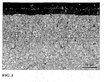
- Fig 1 shows in 2500X magnification a coated cemented carbide substrate according to the present invention in which
- the cutting tool insert according to the present invention includes a cemented carbide substrate with a relatively low amount of cubic carbides, with a medium to highly W-alloyed binder phase and a fine to medium WC grain size.
- This substrate is provided with a wear resisting coating comprising a Ti x Al y N layer and an outer TiN layer.
- a coated cutting tool insert is provided with a cemented carbide body having a composition of 7.9-8.6 wt% Co, preferably 8.0-8.5 wt% Co, most preferably 8.1-8.4 wt% Co; 0.5-2.1 wt%, preferably 0.7-1.8 wt%, most preferably 0.9-1.5 wt% total amount of cubic carbides of the metals Ti, Nb and Ta and balance WC.
- the content of Ti is preferably on a level corresponding to a technical impurity.
- the ratio between the weight concentrations of Ta and Nb is within 1.0-12.0, preferably 1.5-11.4, most preferably 3.0-10.5.
- the cobalt binder phase is medium to highly alloyed with tungsten.
- the S-value depends on the content of tungsten in the binder phase and increases with a decreasing tungsten content.
- the mean intercept length of the tungsten carbide phase measured on a ground and polished representative cross section is in the range 0.4-0.9 ⁇ m, preferably 0.5-0.8 ⁇ m.
- the intercept length is measured by means of image analysis on micrographs with a magnification of 10000x and calculated as the average mean value of approximately 1000 intercept lengths.
- the present invention also relates to a method of making a coated cutting tool with a composition of 7.9-8.6 wt% Co, preferably 8:0-8.5 wt% Co, most preferably 8.1-8.4 wt% Co; 0.5-2.1 wt%, preferably 0.7-1.8 wt%, most preferably 0.9-1.5 wt% total amount of cubic carbides of the metals Ti, Nb and Ta and balance WC.
- Ti, Ta and/or Nb may also be replaced by other carbides of elements from groups IVb, Vb or VIb of the periodic table.
- the content of Ti is preferably on a level corresponding to a technical impurity.
- the ratio between the weight concentrations of Ta and Nb is within 1.0-12.0, preferably 1.5-11.4, most preferably 3.0-10.5.
- the desired mean intercept length depends on the grain size of the starting powders and milling and sintering conditions and has to be determined by experiments.
- the desired S-value depends on the starting powders and sintering conditions and also has to be determined by experiments.
- the coating layers are deposited using PVD technique preferably arc evaporation, with alloyed or composite Ti-Al metal targets.
- the invention also relates to the use of cutting tool inserts according to above for dry milling at high cutting speeds in alloyed steels, tool steels and dry milling in hardened steels at cutting speeds of 50-350 m/min with mean chip thickness values of 0.03-0.18 mm, depending on cutting speed and insert geometry.
- Grade A A cemented carbide substrate in accordance with the invention with the composition 8.2 wt% Co, 1.2 wt% TaC, 0.2 wt% NbC and balance WC, with a binder phase alloyed with W corresponding to an S-value of 0.87 was produced by conventional milling of the powders, pressing of green compacts and subsequent sintering at 1430 °C. Investigation of the microstructure after sintering showed that the mean intercept length of the tungsten carbide phase was 0.7 ⁇ m.
- the substrate was coated in accordance with the invention in an arc evaporation system. Before coating the inserts were degreased in an ultrasonic cleaning line and in situ sputter cleaned with Ti and Ar ions.
- SEM scanning electron microscopy
- Grade B A substrate with composition 10 wt% Co, 0.5 wt% Cr 3 C 2 and balance WC, a binder phase alloyed with W corresponding to an S-value of 0.84, and a mean intercept length of WC in the sintered body of 0.4 ⁇ m was combined with a coating according to Grade A (according to the invention). Operation Face milling Cutter diameter 100 mm Work piece Bar, 600 mm x 80 mm Material SS2244, 250 HB Insert type RPHT1204 Cutting speed 300 m/min Feed 0.25 mm/tooth Depth of cut 2.5 mm Width of cut 80 mm Coolant No Results Tool life (min) Grade A (grade according to invention) 16 Grade B (coating according to invention) 10
- the tool life of Grade A was limited by flank wear.
- the tool life of Grade B was limited by plastic deformation followed by destruction of the cutting edge.
- Grade C A substrate according to grade A (according to the invention).
- the substrate was CVD coated with four subsequent layers deposited during the same coating cycle.
- the third layer was a 1.5 ⁇ m thick layer of Al 2 O 3 deposited at approximately 1000°C and consisting essentially of the ⁇ -phase.
- the tool life was limited by flank wear.
- the better tool life of Grade D was the consequence of the more wear resistant coating according to the invention.
- Grade E A commercial cemented carbide cutting insert with composition 9.4 wt% Co, 7.2 wt% TaC, 0.1 wt% NbC, 3.4 wt% TiC and balance WC.
- the binder phase was alloyed with W corresponding to an S-value of 0.85, and the mean intercept length of the WC was 0.7 ⁇ m.
- the tool life was limited by flank wear and edge chipping.
- the shorter tool life of Grade E shows the negative effect of high cubic carbide content on cutting edge strength and edge chipping resistance.
Abstract
Description
- The present invention relates to a coated cemented carbide insert (cutting tool), particularly useful for milling at high cutting speeds in alloyed steels, tool steels and milling in hardened steels.
- During machining of steels, stainless steels and cast irons with coated cemented carbide tools, the cutting edges are worn according to different wear mechanisms, such as chemical wear, abrasive wear and adhesive wear. At high cutting speeds, the amount of heat generated in the cutting zone is considerable and a plastic deformation of the cutting edge may occur, which in turn yields an enhanced wear by other mechanisms. When milling alloyed steels adhesive wear is often pronounced and edge chipping occurs frequently as a consequence of delamination or cracking of the protective coating.
- The cutting performance with respect to specific wear types can be improved by single actions, however, very often this will have a negative effect on other wear properties. Consequently, successful tool composite materials must be designed as careful optimizations of numerous properties. In the case of milling of alloyed steels and tool steels, often in a hardened state, one important balance is that between the plastic deformation resistance of the cutting edge and the edge chipping resistance. A simple measure to increase the resistance to plastic deformation and also the abrasive wear resistance is to lower the binder phase content. However, this will also diminish the toughness of the cutting insert, which can substantially lower the tool life in applications where vibrations or the presence of casting or forging skin put demands on such properties. An alternative way to increase the deformation resistance is to add cubic carbides like TiC, TaC and/or NbC. However, this addition has a negative influence on edge chipping tendencies and so called comb crack formation. The constitution of the applied wear resistant surface coating is a key factor in the properties of the tool. Thicker and more wear resistant coatings are often applied by the chemical vapor deposition (CVD) method. These coatings often also improves the plastic deformation resistance but can to larger extent impair edge toughness. Coatings produced by physical vapor deposition (PVD), which are often thinner, do not provide as good protection against heat and plastic deformation but give very good edge integrity and consequently shows good protection against edge chipping.
- To improve all tool properties simultaneously is obviously very difficult and numerous properties of both the protective coating and the cemented carbide substrate and the combination thereof have to be considered. Consequently, commercial coated cemented carbide grades have usually been optimized with respect to one or a few wear types. This also means that they have been optimized for specific application areas.
-
US 6,062,776 discloses a coated cutting insert particularly useful for milling of low and medium alloyed steels and stainless steels with raw surfaces such as cast skin, forged skin, hot or cold rolled skin or pre-machined surfaces under unstable conditions. The insert is characterized by a WC-Co cemented carbide with a low content of cubic carbides and a rather low W-alloyed binder phase and a coating including an innermost layer of TiCxNyOz with columnar grains and a top layer of TiN and an inner layer of κ-Al2O3. -
US 6,177,178 describes a coated milling insert particularly useful for milling in low and medium alloyed steels with or without raw surface zones during wet or dry conditions. The insert is characterized by a WC-Co cemented carbide with a low content of cubic carbides and a highly W-alloyed binder phase and a coating including an inner layer of TiCxNyOz with columnar grains, an inner layer of κ-Al2O3 and, preferably, a top layer of TiN. -
US 6,250,855 provides a coated cemented carbide cutting tool for wet and dry milling of stainless steels at high cutting speeds. The tool has a cemented carbide body comprising a substrate based on WC-Co without any additions of cubic carbides. The coating includes a very thin layer of TiN, a second layer of (Ti,Al)N with a periodic variation of the Ti/Al ratio and an outermost layer of TiN. -
WO 01/16389 -
EP 1103635 provides a cutting tool insert particularly useful for wet and dry milling of low and medium alloyed steels and stainless steels as well as for turning of stainless steels. The cutting tool is comprised of a cobalt cemented carbide substrate with a multi-layer refractory coating thereon. The substrate has a cobalt content of 9.0-10.9 wt% and contains 1.0-2.0 wt% TaC/NbC. The coating consists of an MTCVD TiCxNyOz layer and a multi-layer coating being composed of κ-Al2O3 and TiCxNyOz layers. -
EP-A-01038989 -
WO01/16388 - The substrate is coated with layers of (TixAl1-x)N.
- It has now been found that enhanced cutting performance can be obtained by combining many different features of the cutting tool. Preferably for milling, the cutting insert has excellent performance at high cutting speeds in alloyed steels, tool steels and milling in hardened steels. At these cutting conditions, the cutting tool according to the invention displays improved properties with respect to many of the wear types mentioned earlier.
-
Fig 1 shows in 2500X magnification a coated cemented carbide substrate according to the present invention in which - 1. Cemented carbide body.
- 2. An innermost layer of TixAlyN.
- 3. An outermost layer of TiN.
- The cutting tool insert according to the present invention includes a cemented carbide substrate with a relatively low amount of cubic carbides, with a medium to highly W-alloyed binder phase and a fine to medium WC grain size. This substrate is provided with a wear resisting coating comprising a TixAlyN layer and an outer TiN layer.
- According to the present invention, a coated cutting tool insert is provided with a cemented carbide body having a composition of 7.9-8.6 wt% Co, preferably 8.0-8.5 wt% Co, most preferably 8.1-8.4 wt% Co; 0.5-2.1 wt%, preferably 0.7-1.8 wt%, most preferably 0.9-1.5 wt% total amount of cubic carbides of the metals Ti, Nb and Ta and balance WC. The content of Ti is preferably on a level corresponding to a technical impurity. In a preferred embodiment, the ratio between the weight concentrations of Ta and Nb is within 1.0-12.0, preferably 1.5-11.4, most preferably 3.0-10.5.
- The cobalt binder phase is medium to highly alloyed with tungsten. The content of W in the binder phase may be expressed as the S-value=σ/16.1, where σ is the measured magnetic moment of the binder phase in µTm3kg-1. The S-value depends on the content of tungsten in the binder phase and increases with a decreasing tungsten content. Thus, for pure cobalt, or a binder in a cemented carbide that is saturated with carbon, S=1 and for a binder phase that contains W in an amount that corresponds to the borderline to formation of η-phase, S=0.78.
- It has now been found according to the present invention that improved cutting performance is achieved if the cemented carbide body has an S-value within the range 0.81-0.95, preferably 0.82-0.94, most preferably 0.85-0.92.
- Furthermore, the mean intercept length of the tungsten carbide phase measured on a ground and polished representative cross section is in the range 0.4-0.9 µm, preferably 0.5-0.8 µm. The intercept length is measured by means of image analysis on micrographs with a magnification of 10000x and calculated as the average mean value of approximately 1000 intercept lengths.
- The coating according to a preferred embodiment includes:
- at least one layer of TixAlyN, 0.8<x+y<1.2, with 0.25≤x/y≤1.45, preferably 0.33≤x/y≤1.1, most preferably 0.42≤x/y≤0.79 with a thickness of 0.5-7 µm, preferably 1-6 µm, most preferably 2-5 µm, with columnar grains.
- the outermost TixAlyN layer can be followed by a layer of TiN with a thickness of 0.1-2 µm, preferably 0.1-1.5 µm, most preferably 0.2-1 µm, but a TixAlyN layer can also be the outermost layer.
- The present invention also relates to a method of making a coated cutting tool with a composition of 7.9-8.6 wt% Co, preferably 8:0-8.5 wt% Co, most preferably 8.1-8.4 wt% Co; 0.5-2.1 wt%, preferably 0.7-1.8 wt%, most preferably 0.9-1.5 wt% total amount of cubic carbides of the metals Ti, Nb and Ta and balance WC. Ti, Ta and/or Nb may also be replaced by other carbides of elements from groups IVb, Vb or VIb of the periodic table. The content of Ti is preferably on a level corresponding to a technical impurity. In a preferred embodiment, the ratio between the weight concentrations of Ta and Nb is within 1.0-12.0, preferably 1.5-11.4, most preferably 3.0-10.5.
- The desired mean intercept length depends on the grain size of the starting powders and milling and sintering conditions and has to be determined by experiments. The desired S-value depends on the starting powders and sintering conditions and also has to be determined by experiments.
- The coating layers are deposited using PVD technique preferably arc evaporation, with alloyed or composite Ti-Al metal targets.
- The invention also relates to the use of cutting tool inserts according to above for dry milling at high cutting speeds in alloyed steels, tool steels and dry milling in hardened steels at cutting speeds of 50-350 m/min with mean chip thickness values of 0.03-0.18 mm, depending on cutting speed and insert geometry.
- Grade A: A cemented carbide substrate in accordance with the invention with the composition 8.2 wt% Co, 1.2 wt% TaC, 0.2 wt% NbC and balance WC, with a binder phase alloyed with W corresponding to an S-value of 0.87 was produced by conventional milling of the powders, pressing of green compacts and subsequent sintering at 1430 °C. Investigation of the microstructure after sintering showed that the mean intercept length of the tungsten carbide phase was 0.7 µm. The substrate was coated in accordance with the invention in an arc evaporation system. Before coating the inserts were degreased in an ultrasonic cleaning line and in situ sputter cleaned with Ti and Ar ions. During deposition, the inserts were attached to a threefold rotating fixture which was negatively biased. Ti and alloyed Ti-Al metal targets were used and the deposition was made in a N2 containing gas mixture. The temperature was kept at 500 °C during the one hour deposition cycle. Two subsequent layers were deposited during the same coating cycle, a 3.4 µm thick TixAlyN layer with x/y=0.55, followed by a 0.2 µm thick TiN layer. The thickness of the individual layers was measured on the flank face of the inserts using scanning electron microscopy (SEM) on cross-section specimens. The x/y metal ratio was determined using energy dispersive X-ray spectroscopy (EDS) in the SEM. See
Fig 1 . - Grade B: A substrate with
composition 10 wt% Co, 0.5 wt% Cr3C2 and balance WC, a binder phase alloyed with W corresponding to an S-value of 0.84, and a mean intercept length of WC in the sintered body of 0.4 µm was combined with a coating according to Grade A (according to the invention).Operation Face milling Cutter diameter 100 mm Work piece Bar, 600 mm x 80 mm Material SS2244, 250 HB Insert type RPHT1204 Cutting speed 300 m/min Feed 0.25 mm/tooth Depth of cut 2.5 mm Width of cut 80 mm Coolant No Results Tool life (min) Grade A (grade according to invention) 16 Grade B (coating according to invention) 10 - The tool life of Grade A was limited by flank wear. The tool life of Grade B was limited by plastic deformation followed by destruction of the cutting edge. This test shows that the combination of the substrate and coating according to the invention exhibits longer tool life than the coating in combination with a prior art substrate produced without addition of cubic carbides and with WC that yields a much finer mean intercept length in the sintered body.
- Grade C: A substrate according to grade A (according to the invention). The substrate was CVD coated with four subsequent layers deposited during the same coating cycle. First a 0.3 µm thick TiCxNyOz layer with z<0.1 and approximately x/y=0.1, having equiaxed grains. The second layer was 3.1 µm of columnar TiCxNyOz deposited at 835-850°C using MTCVD technique, yielding an approximated carbon to nitrogen ratio x/y=1.5 with z<0.1. The third layer was a 1.5 µm thick layer of Al2O3 deposited at approximately 1000°C and consisting essentially of the κ-phase. Finally a layer of equiaxed nitrogen rich TiCxNyOz with z<0.1 and y>0.8 was deposited to a thickness of 0.3 µm.
Operation Copy milling Cutter diameter 35 mm Work piece Bar, 350 mm x 270 mm Material SS2314, 40 HRC Insert type RPHT1204 Cutting speed 200 m/min Feed 0.2 mm/tooth Number of teeth 3 Depth of cut 2 mm Width of cut 5-32 mm Coolant No Results Tool life (min) Grade A (grade according to invention) 40 Grade C (substrate according to invention) 25 - The tool life of both grades was limited by edge chipping. The tool life of Grade C was significantly reduced by adhesive wear leading to pick out of the coating and premature edge chipping. This test shows that the combination of the substrate and coating according to the invention exhibits longer tool life than the substrate in combination with a thicker prior art CVD coating.
- Grade D: A substrate according to grade A (according to the invention). The substrate was coated using PVD technique with two subsequent layers deposited during the same coating cycle: a 3.2 µm thick TixAlyN layer with x/y=1.63 followed by a 0.2 µm thick TiN layer.
Operation Face milling Cutter diameter 100 mm Work piece Bar, 75 mm x 600 mm Material SS2244, 250 HB Insert type SEKN 1203 Cutting speed 250 m/min Feed 0.25 mm/tooth Depth of cut 2.5 mm Width of cut 75 mm Coolant No Results Tool life (min) Grade A (grade according to invention) 21 Grade D (prior art) 15 - The tool life was limited by flank wear. The better tool life of Grade D was the consequence of the more wear resistant coating according to the invention.
- Grade E: A commercial cemented carbide cutting insert with composition 9.4 wt% Co, 7.2 wt% TaC, 0.1 wt% NbC, 3.4 wt% TiC and balance WC. The binder phase was alloyed with W corresponding to an S-value of 0.85, and the mean intercept length of the WC was 0.7 µm. The insert was coated with a 1.5 µm (measured on the flank face) thick TixAlyN layer with an elemental ratio x/y=1.2.
Operation Copy milling Cutter diameter 35 mm Work piece Bar, 350 mm x 270 mm Material SS2242, 38 HRC Insert type RPHT1204 Cutting speed 200 m/min Feed 0.22 mm/tooth Number of teeth 3 Depth of cut 2 mm Width of cut 5-32 mm Coolant No Results Tool life (min) Grade A (grade according to invention) 56 Grade E (prior art) 41 - The tool life was limited by flank wear and edge chipping. The shorter tool life of Grade E shows the negative effect of high cubic carbide content on cutting edge strength and edge chipping resistance.
Claims (7)
- A cutting tool insert, comprising a cemented carbide body and a coating particularly useful in milling at high cutting speeds in alloyed steels, tool steels and milling in hardened steels c h a racterized by a composition of the cemented carbide body of 7.9-8.6 wt% Co, preferably 8.0-8.5 wt% Co, 0.5-2.1 wt%, preferably 0.7-1.8 wt%, total amount of cubic carbides of the metals Ta and Nb, the ratio between the weight concentrations of Ta and Nb being within 1.0-12.0, preferably 1.5-11.4, and balance WC with a mean intercept length in the range 0.4-0.9 µm, preferably 0.5-0.8 µm, the binder phase being alloyed with W corresponding to an S-value within the range 0.81-0.95, preferably 0.82-0.94 and that said coating comprises a layer of TixAlyN ,0.8≤x+y≤1.2, with 0.25≤x/y≤1.45, preferably 0.33≤x/y≤1.1, with a thickness of 0.5-7 µm, preferably 1-6 µm, with columnar grains.
- A cutting tool insert according to claim 1 characterized in a coating consisting of one layer of TixAlyN with 0.8≤x+y≤1.2 and 0.42≤x/y≤0.79.
- A cutting tool according to the preceding claims characterized in further comprising an outer layer of TiN with a thickness of 0.1-2 µm, preferably 0.1-1.5 µm.
- A method of making a cutting tool insert, comprising a cemented carbide body and a coating particularly useful in milling at high cutting speeds in low and medium alloyed steels and milling in hardened steels characterized in depositing on a cemented carbide with a composition of 7.9-8.6 wt% Co, preferably 8.0-8.5 wt% Co, 0.5-2.1 wt%, preferably 0.7-1.8 wt%, total amount of cubic carbides of the metals Ta and Nb, the ratio between the weight concentrations of Ta and Nb being within 1.0-12.0, preferably 1.5-11.4, and balance WC with a mean intercept length in the range 0.4-0.9 µm, preferably 0.5-0.8 µm, the binder phase being alloyed with W corresponding to an S-value within the range 0.81-0.95, preferably 0.82-0.94 a coating comprising a layer of TixAlyN with 0.25≤x/y≤1.45, preferably 0.33≤x/y≤1.1, with a thickness of 0.5-7 µm, preferably 1-6 µm, with columnar grains using PVD-technique, preferably arc evaporation.
- The method of claim 4 characterized in depositing TixAlyN with 0.8≤x+y≤1.2 and 0.42≤x/y≤0.79 using known PVD-technique.
- The method of claims 4-5 characterized in depositing an outer layer of TiN with thickness of 0.1-2 µm, preferably 0.1-1.5 µm using known PVD-technique.
- Use of a cutting tool insert according to claims 1-6 for dry milling at high cutting speeds in alloyed steels, tool steels and dry milling in hardened steels at cutting speeds of 50-350 m/min at mean chip thickness values of 0.03-0.18 mm, depending on cutting speed and insert geometry.
Applications Claiming Priority (2)
| Application Number | Priority Date | Filing Date | Title |
|---|---|---|---|
| SE0200871A SE523826C2 (en) | 2002-03-20 | 2002-03-20 | Cutter coated with TiAIN for high speed machining of alloy steels, ways of making a cutter and use of the cutter |
| SE0200871 | 2002-03-20 |
Publications (2)
| Publication Number | Publication Date |
|---|---|
| EP1347076A1 EP1347076A1 (en) | 2003-09-24 |
| EP1347076B1 true EP1347076B1 (en) | 2008-02-27 |
Family
ID=20287351
Family Applications (1)
| Application Number | Title | Priority Date | Filing Date |
|---|---|---|---|
| EP03005967A Expired - Lifetime EP1347076B1 (en) | 2002-03-20 | 2003-03-18 | PVD-Coated cutting tool insert |
Country Status (9)
| Country | Link |
|---|---|
| US (1) | US6884497B2 (en) |
| EP (1) | EP1347076B1 (en) |
| JP (1) | JP2003326415A (en) |
| KR (1) | KR20030076380A (en) |
| CN (1) | CN1301341C (en) |
| AT (1) | ATE387519T1 (en) |
| CZ (1) | CZ2003819A3 (en) |
| DE (1) | DE60319295T2 (en) |
| SE (1) | SE523826C2 (en) |
Cited By (6)
| Publication number | Priority date | Publication date | Assignee | Title |
|---|---|---|---|---|
| US7938878B2 (en) | 2007-06-01 | 2011-05-10 | Sandvik Intellectual Property Ab | Fine grained cemented carbide with refined structure |
| US7976607B2 (en) | 2006-06-15 | 2011-07-12 | Sandvik Intellectual Property Ab | Cemented carbide with refined structure |
| US8084148B2 (en) | 2007-09-13 | 2011-12-27 | Seco Tools Ab | Insert for milling of cast iron |
| US8283058B2 (en) | 2007-06-01 | 2012-10-09 | Sandvik Intellectual Property Ab | Fine grained cemented carbide cutting tool insert |
| US8455116B2 (en) | 2007-06-01 | 2013-06-04 | Sandvik Intellectual Property Ab | Coated cemented carbide cutting tool insert |
| CN106457355A (en) * | 2014-06-09 | 2017-02-22 | 山特维克知识产权股份有限公司 | Cemented carbide necking tool |
Families Citing this family (37)
| Publication number | Priority date | Publication date | Assignee | Title |
|---|---|---|---|---|
| SE526604C2 (en) * | 2002-03-22 | 2005-10-18 | Seco Tools Ab | Coated cutting tool for turning in steel |
| SE526674C2 (en) | 2003-03-24 | 2005-10-25 | Seco Tools Ab | Coated cemented carbide insert |
| DE102004010285A1 (en) * | 2004-03-03 | 2005-09-29 | Walter Ag | Coating for a cutting tool and manufacturing process |
| SE528427C2 (en) * | 2004-07-09 | 2006-11-07 | Seco Tools Ab | A coated cutter for metalworking and ways to manufacture it |
| US7651794B2 (en) * | 2005-04-28 | 2010-01-26 | Hitachi Global Storage Technologies Netherlands B.V. | Adhesion layer for thin film magnetic recording medium |
| SE529590C2 (en) * | 2005-06-27 | 2007-09-25 | Sandvik Intellectual Property | Fine-grained sintered cemented carbides containing a gradient zone |
| US8637127B2 (en) | 2005-06-27 | 2014-01-28 | Kennametal Inc. | Composite article with coolant channels and tool fabrication method |
| US7670674B2 (en) * | 2005-09-09 | 2010-03-02 | Sandvik Intellectual Property Ab | PVD coated cutting tool |
| SE529015C2 (en) * | 2005-09-09 | 2007-04-10 | Sandvik Intellectual Property | PVD coated cutting tool inserts made of cemented carbide |
| SE529431C2 (en) * | 2005-12-14 | 2007-08-07 | Sandvik Intellectual Property | Coated cemented carbide insert, ways of making this and its use for turning |
| SE530253C2 (en) * | 2005-12-14 | 2008-04-08 | Sandvik Intellectual Property | Carbide inserts, its manufacture and use for wear-requiring cutting and grooving in hot-strength super alloys and stainless steel |
| KR100651234B1 (en) * | 2006-02-15 | 2006-11-30 | (주)모악환경산업 | Apparatus forreproducing recycle-sand, crushing construction-waste |
| JPWO2007111301A1 (en) * | 2006-03-28 | 2009-08-13 | 京セラ株式会社 | Surface coating tool |
| RU2432445C2 (en) | 2006-04-27 | 2011-10-27 | Ти Ди Уай Индастриз, Инк. | Modular drill bit with fixed cutting elements, body of this modular drill bit and methods of their manufacturing |
| KR100771968B1 (en) * | 2006-09-01 | 2007-11-01 | 한국야금 주식회사 | Pvd coated cutting tool with high wear resistance |
| JP5330255B2 (en) | 2006-10-25 | 2013-10-30 | ティーディーワイ・インダストリーズ・エルエルシー | Articles with improved thermal crack resistance |
| US8512882B2 (en) * | 2007-02-19 | 2013-08-20 | TDY Industries, LLC | Carbide cutting insert |
| SE0701320L (en) * | 2007-06-01 | 2008-12-02 | Sandvik Intellectual Property | Coated cemented carbide for mold tool applications |
| SE0701321L (en) * | 2007-06-01 | 2008-12-02 | Sandvik Intellectual Property | Coated cutting |
| WO2009002266A1 (en) * | 2007-06-27 | 2008-12-31 | Sandvik Intellectual Property Ab | Coated cemented carbide inserts for milling of especially hard cast steel |
| SE531971C2 (en) | 2007-08-24 | 2009-09-15 | Seco Tools Ab | Coated cutting tool for general turning in hot-strength super alloys (HRSA) |
| SE532043C2 (en) | 2007-10-10 | 2009-10-06 | Seco Tools Ab | CVD coated cutter for milling and manufacturing method |
| US8790439B2 (en) | 2008-06-02 | 2014-07-29 | Kennametal Inc. | Composite sintered powder metal articles |
| CN101580938B (en) * | 2009-06-19 | 2012-10-03 | 吉林大学 | Method for preparing metallic matrix composite coating reinforced by alumina ceramics particles |
| CN101580939B (en) * | 2009-06-19 | 2011-06-01 | 吉林大学 | Method for preparing metallic matrix composite coating reinforced by tungsten carbide ceramics particles |
| CN102190728B (en) | 2010-03-17 | 2014-07-02 | 永卓博济(上海)生物医药技术有限公司 | Novel humanized anti-CD20 monoclonal antibody |
| US8800848B2 (en) | 2011-08-31 | 2014-08-12 | Kennametal Inc. | Methods of forming wear resistant layers on metallic surfaces |
| US9016406B2 (en) | 2011-09-22 | 2015-04-28 | Kennametal Inc. | Cutting inserts for earth-boring bits |
| JP5477671B2 (en) * | 2012-02-28 | 2014-04-23 | 三菱マテリアル株式会社 | Metal nitride material for thermistor, manufacturing method thereof, and film type thermistor sensor |
| JP5477670B2 (en) * | 2012-02-28 | 2014-04-23 | 三菱マテリアル株式会社 | Metal nitride material for thermistor, manufacturing method thereof, and film type thermistor sensor |
| CN103567473A (en) * | 2012-07-24 | 2014-02-12 | 洪泽县汽车半轴制造有限公司 | Nano ceramic cutting tool for processing automotive axle shafts |
| JP6044322B2 (en) * | 2012-12-20 | 2016-12-14 | 三菱マテリアル株式会社 | Surface coated cutting tool with excellent chipping and wear resistance with excellent hard coating layer |
| AT15220U1 (en) * | 2016-03-07 | 2017-03-15 | Ceratizit Austria Gmbh | Process for producing a hard material layer on a substrate, hard material layer, cutting tool and coating source |
| CN106521214A (en) * | 2017-01-04 | 2017-03-22 | 东莞宜安科技股份有限公司 | Composite metal ceramic and application thereof |
| US10570501B2 (en) | 2017-05-31 | 2020-02-25 | Kennametal Inc. | Multilayer nitride hard coatings |
| WO2019065683A1 (en) | 2017-09-29 | 2019-04-04 | 三菱マテリアル株式会社 | Surface-coated cutting tool in which hard coating layer exhibits exceptional adhesion resistance and anomalous damage resistance |
| JP7256978B2 (en) * | 2017-09-29 | 2023-04-13 | 三菱マテリアル株式会社 | A surface-coated cutting tool with a hard coating layer that exhibits excellent adhesion resistance and abnormal damage resistance. |
Family Cites Families (22)
| Publication number | Priority date | Publication date | Assignee | Title |
|---|---|---|---|---|
| JPH04128362A (en) * | 1990-09-18 | 1992-04-28 | Sumitomo Metal Mining Co Ltd | Wear resistant hard film coated steel material |
| JP2918133B2 (en) * | 1992-05-25 | 1999-07-12 | 三菱マテリアル株式会社 | Surface coated cutting tool |
| SE509201C2 (en) * | 1994-07-20 | 1998-12-14 | Sandvik Ab | Aluminum oxide coated tool |
| SE511210C2 (en) * | 1995-09-01 | 1999-08-23 | Sandvik Ab | Coated cutting tool insert |
| SE9504304D0 (en) | 1995-11-30 | 1995-11-30 | Sandvik Ab | Coated milling insert |
| KR100430360B1 (en) | 1995-11-30 | 2004-07-16 | 산드빅 악티에볼라그 | Coated cutting insert and method of making it |
| US5879823A (en) * | 1995-12-12 | 1999-03-09 | Kennametal Inc. | Coated cutting tool |
| DE59709451D1 (en) * | 1996-09-03 | 2003-04-10 | Unaxis Balzers Ag | WEAR PROTECTION-COATED WORKPIECE |
| SE517474C2 (en) * | 1996-10-11 | 2002-06-11 | Sandvik Ab | Way to manufacture cemented carbide with binder phase enriched surface zone |
| JP3451857B2 (en) * | 1996-11-25 | 2003-09-29 | 三菱マテリアル株式会社 | Surface-coated cemented carbide cutting tool with excellent wear resistance |
| US5984593A (en) * | 1997-03-12 | 1999-11-16 | Kennametal Inc. | Cutting insert for milling titanium and titanium alloys |
| EP1029945A1 (en) * | 1999-02-17 | 2000-08-23 | Balzers Aktiengesellschaft | Method for coating tools |
| JP2000005904A (en) * | 1998-06-18 | 2000-01-11 | Sumitomo Metal Mining Co Ltd | Surface treated steel based cutting tool |
| US6492011B1 (en) * | 1998-09-02 | 2002-12-10 | Unaxis Trading Ag | Wear-resistant workpiece and method for producing same |
| SE519005C2 (en) | 1999-03-26 | 2002-12-17 | Sandvik Ab | Coated cemented carbide inserts |
| AUPQ120099A0 (en) | 1999-06-25 | 1999-07-22 | Telefonaktiebolaget Lm Ericsson (Publ) | Switch structure |
| SE9903089D0 (en) * | 1999-09-01 | 1999-09-01 | Sandvik Ab | Coated grooving or parting insert |
| DE60012850T2 (en) | 1999-11-25 | 2005-02-03 | Seco Tools Ab | Coated cutting insert for milling and turning applications |
| JP3599628B2 (en) * | 2000-02-25 | 2004-12-08 | 株式会社タンガロイ | Composite hard film coated member |
| JP2002126913A (en) * | 2000-10-25 | 2002-05-08 | Toshiba Tungaloy Co Ltd | High adhesion hard film-covered tool and its manufacturing method |
| DE10115390A1 (en) * | 2000-12-22 | 2002-06-27 | Mitsubishi Materials Corp Toki | Coated cutting tool |
| JP2002356734A (en) * | 2001-05-30 | 2002-12-13 | Kyocera Corp | Hard metal alloy, and cutting tool using it |
-
2002
- 2002-03-20 SE SE0200871A patent/SE523826C2/en not_active IP Right Cessation
-
2003
- 2003-03-11 JP JP2003064682A patent/JP2003326415A/en active Pending
- 2003-03-18 AT AT03005967T patent/ATE387519T1/en active
- 2003-03-18 EP EP03005967A patent/EP1347076B1/en not_active Expired - Lifetime
- 2003-03-18 DE DE60319295T patent/DE60319295T2/en not_active Expired - Lifetime
- 2003-03-18 US US10/389,737 patent/US6884497B2/en not_active Expired - Fee Related
- 2003-03-19 KR KR10-2003-0017129A patent/KR20030076380A/en not_active Application Discontinuation
- 2003-03-20 CN CNB031073476A patent/CN1301341C/en not_active Expired - Fee Related
- 2003-03-20 CZ CZ2003819A patent/CZ2003819A3/en unknown
Cited By (7)
| Publication number | Priority date | Publication date | Assignee | Title |
|---|---|---|---|---|
| US7976607B2 (en) | 2006-06-15 | 2011-07-12 | Sandvik Intellectual Property Ab | Cemented carbide with refined structure |
| US7938878B2 (en) | 2007-06-01 | 2011-05-10 | Sandvik Intellectual Property Ab | Fine grained cemented carbide with refined structure |
| US8283058B2 (en) | 2007-06-01 | 2012-10-09 | Sandvik Intellectual Property Ab | Fine grained cemented carbide cutting tool insert |
| US8455116B2 (en) | 2007-06-01 | 2013-06-04 | Sandvik Intellectual Property Ab | Coated cemented carbide cutting tool insert |
| US9005329B2 (en) | 2007-06-01 | 2015-04-14 | Sandvik Intellectual Property Ab | Fine grained cemented carbide with refined structure |
| US8084148B2 (en) | 2007-09-13 | 2011-12-27 | Seco Tools Ab | Insert for milling of cast iron |
| CN106457355A (en) * | 2014-06-09 | 2017-02-22 | 山特维克知识产权股份有限公司 | Cemented carbide necking tool |
Also Published As
| Publication number | Publication date |
|---|---|
| DE60319295T2 (en) | 2009-02-26 |
| ATE387519T1 (en) | 2008-03-15 |
| CN1445037A (en) | 2003-10-01 |
| SE523826C2 (en) | 2004-05-25 |
| US6884497B2 (en) | 2005-04-26 |
| SE0200871D0 (en) | 2002-03-20 |
| CZ2003819A3 (en) | 2004-01-14 |
| DE60319295D1 (en) | 2008-04-10 |
| KR20030076380A (en) | 2003-09-26 |
| CN1301341C (en) | 2007-02-21 |
| JP2003326415A (en) | 2003-11-18 |
| EP1347076A1 (en) | 2003-09-24 |
| SE0200871L (en) | 2003-09-21 |
| US20030219633A1 (en) | 2003-11-27 |
Similar Documents
| Publication | Publication Date | Title |
|---|---|---|
| EP1347076B1 (en) | PVD-Coated cutting tool insert | |
| EP1218557B1 (en) | Coated grooving or parting insert | |
| US20090214306A1 (en) | Coated Cutting Tool Insert | |
| KR20080055735A (en) | Coated cemented carbide endmill | |
| EP1103635B1 (en) | Coated cutting insert for milling and turning applications | |
| EP1997938A2 (en) | Coated cutting tool insert | |
| KR20110100621A (en) | Improved coated cutting insert for rough turning | |
| US8192793B2 (en) | Coated cutting insert for milling applications | |
| US8142848B2 (en) | Coated cutting insert for milling | |
| EP1493845B1 (en) | CVD coated cutting tool insert | |
| US8142621B2 (en) | Insert for milling of cast iron | |
| EP1352697B1 (en) | Coated cutting tool insert | |
| EP1757388B1 (en) | Surface-coated cutware and process for producing the same | |
| JP2004136430A (en) | Coated tool | |
| KR20210118093A (en) | hard film cutting tool | |
| EP2075350A2 (en) | CVD coated cutting tool insert for milling | |
| JPH09241825A (en) | High strength coated body | |
| JP2003129165A (en) | Surface coated hard alloy | |
| EP2201153A1 (en) | Insert for milling of cast iron | |
| JPH0919807A (en) | Surface-covered cutting tool of wc-based super-hard alloy |
Legal Events
| Date | Code | Title | Description |
|---|---|---|---|
| PUAI | Public reference made under article 153(3) epc to a published international application that has entered the european phase |
Free format text: ORIGINAL CODE: 0009012 |
|
| AK | Designated contracting states |
Kind code of ref document: A1 Designated state(s): AT BE BG CH CY CZ DE DK EE ES FI FR GB GR HU IE IT LI LU MC NL PT RO SE SI SK TR |
|
| AX | Request for extension of the european patent |
Extension state: AL LT LV MK RO |
|
| AKX | Designation fees paid | ||
| REG | Reference to a national code |
Ref country code: DE Ref legal event code: 8566 |
|
| 17P | Request for examination filed |
Effective date: 20040324 |
|
| RBV | Designated contracting states (corrected) |
Designated state(s): AT BE BG CH CY CZ DE DK EE ES FI FR GB GR HU IE IT LI LU MC NL PT SE SI SK TR |
|
| RBV | Designated contracting states (corrected) |
Designated state(s): AT BE BG CH CY CZ DE DK EE ES FI FR GB GR HU IE IT LI LU MC NL PT RO SE SI SK TR |
|
| GRAP | Despatch of communication of intention to grant a patent |
Free format text: ORIGINAL CODE: EPIDOSNIGR1 |
|
| GRAS | Grant fee paid |
Free format text: ORIGINAL CODE: EPIDOSNIGR3 |
|
| GRAA | (expected) grant |
Free format text: ORIGINAL CODE: 0009210 |
|
| AK | Designated contracting states |
Kind code of ref document: B1 Designated state(s): AT BE BG CH CY CZ DE DK EE ES FI FR GB GR HU IE IT LI LU MC NL PT RO SE SI SK TR |
|
| REG | Reference to a national code |
Ref country code: GB Ref legal event code: FG4D |
|
| REG | Reference to a national code |
Ref country code: CH Ref legal event code: EP Ref country code: CH Ref legal event code: NV Representative=s name: BOVARD AG PATENTANWAELTE |
|
| REG | Reference to a national code |
Ref country code: IE Ref legal event code: FG4D |
|
| REF | Corresponds to: |
Ref document number: 60319295 Country of ref document: DE Date of ref document: 20080410 Kind code of ref document: P |
|
| REG | Reference to a national code |
Ref country code: SE Ref legal event code: TRGR |
|
| PG25 | Lapsed in a contracting state [announced via postgrant information from national office to epo] |
Ref country code: ES Free format text: LAPSE BECAUSE OF FAILURE TO SUBMIT A TRANSLATION OF THE DESCRIPTION OR TO PAY THE FEE WITHIN THE PRESCRIBED TIME-LIMIT Effective date: 20080607 Ref country code: FI Free format text: LAPSE BECAUSE OF FAILURE TO SUBMIT A TRANSLATION OF THE DESCRIPTION OR TO PAY THE FEE WITHIN THE PRESCRIBED TIME-LIMIT Effective date: 20080227 |
|
| NLV1 | Nl: lapsed or annulled due to failure to fulfill the requirements of art. 29p and 29m of the patents act | ||
| PG25 | Lapsed in a contracting state [announced via postgrant information from national office to epo] |
Ref country code: SI Free format text: LAPSE BECAUSE OF FAILURE TO SUBMIT A TRANSLATION OF THE DESCRIPTION OR TO PAY THE FEE WITHIN THE PRESCRIBED TIME-LIMIT Effective date: 20080227 Ref country code: BE Free format text: LAPSE BECAUSE OF FAILURE TO SUBMIT A TRANSLATION OF THE DESCRIPTION OR TO PAY THE FEE WITHIN THE PRESCRIBED TIME-LIMIT Effective date: 20080227 |
|
| PG25 | Lapsed in a contracting state [announced via postgrant information from national office to epo] |
Ref country code: SK Free format text: LAPSE BECAUSE OF FAILURE TO SUBMIT A TRANSLATION OF THE DESCRIPTION OR TO PAY THE FEE WITHIN THE PRESCRIBED TIME-LIMIT Effective date: 20080227 Ref country code: NL Free format text: LAPSE BECAUSE OF FAILURE TO SUBMIT A TRANSLATION OF THE DESCRIPTION OR TO PAY THE FEE WITHIN THE PRESCRIBED TIME-LIMIT Effective date: 20080227 Ref country code: PT Free format text: LAPSE BECAUSE OF FAILURE TO SUBMIT A TRANSLATION OF THE DESCRIPTION OR TO PAY THE FEE WITHIN THE PRESCRIBED TIME-LIMIT Effective date: 20080721 Ref country code: CZ Free format text: LAPSE BECAUSE OF FAILURE TO SUBMIT A TRANSLATION OF THE DESCRIPTION OR TO PAY THE FEE WITHIN THE PRESCRIBED TIME-LIMIT Effective date: 20080227 Ref country code: DK Free format text: LAPSE BECAUSE OF FAILURE TO SUBMIT A TRANSLATION OF THE DESCRIPTION OR TO PAY THE FEE WITHIN THE PRESCRIBED TIME-LIMIT Effective date: 20080227 Ref country code: MC Free format text: LAPSE BECAUSE OF NON-PAYMENT OF DUE FEES Effective date: 20080331 |
|
| ET | Fr: translation filed | ||
| PG25 | Lapsed in a contracting state [announced via postgrant information from national office to epo] |
Ref country code: RO Free format text: LAPSE BECAUSE OF FAILURE TO SUBMIT A TRANSLATION OF THE DESCRIPTION OR TO PAY THE FEE WITHIN THE PRESCRIBED TIME-LIMIT Effective date: 20080227 |
|
| PLBE | No opposition filed within time limit |
Free format text: ORIGINAL CODE: 0009261 |
|
| STAA | Information on the status of an ep patent application or granted ep patent |
Free format text: STATUS: NO OPPOSITION FILED WITHIN TIME LIMIT |
|
| PG25 | Lapsed in a contracting state [announced via postgrant information from national office to epo] |
Ref country code: IE Free format text: LAPSE BECAUSE OF NON-PAYMENT OF DUE FEES Effective date: 20080318 Ref country code: EE Free format text: LAPSE BECAUSE OF FAILURE TO SUBMIT A TRANSLATION OF THE DESCRIPTION OR TO PAY THE FEE WITHIN THE PRESCRIBED TIME-LIMIT Effective date: 20080227 |
|
| 26N | No opposition filed |
Effective date: 20081128 |
|
| PG25 | Lapsed in a contracting state [announced via postgrant information from national office to epo] |
Ref country code: BG Free format text: LAPSE BECAUSE OF FAILURE TO SUBMIT A TRANSLATION OF THE DESCRIPTION OR TO PAY THE FEE WITHIN THE PRESCRIBED TIME-LIMIT Effective date: 20080527 |
|
| PG25 | Lapsed in a contracting state [announced via postgrant information from national office to epo] |
Ref country code: CY Free format text: LAPSE BECAUSE OF FAILURE TO SUBMIT A TRANSLATION OF THE DESCRIPTION OR TO PAY THE FEE WITHIN THE PRESCRIBED TIME-LIMIT Effective date: 20080227 |
|
| PG25 | Lapsed in a contracting state [announced via postgrant information from national office to epo] |
Ref country code: HU Free format text: LAPSE BECAUSE OF FAILURE TO SUBMIT A TRANSLATION OF THE DESCRIPTION OR TO PAY THE FEE WITHIN THE PRESCRIBED TIME-LIMIT Effective date: 20080828 Ref country code: LU Free format text: LAPSE BECAUSE OF NON-PAYMENT OF DUE FEES Effective date: 20080318 |
|
| PG25 | Lapsed in a contracting state [announced via postgrant information from national office to epo] |
Ref country code: TR Free format text: LAPSE BECAUSE OF FAILURE TO SUBMIT A TRANSLATION OF THE DESCRIPTION OR TO PAY THE FEE WITHIN THE PRESCRIBED TIME-LIMIT Effective date: 20080227 |
|
| PG25 | Lapsed in a contracting state [announced via postgrant information from national office to epo] |
Ref country code: GR Free format text: LAPSE BECAUSE OF FAILURE TO SUBMIT A TRANSLATION OF THE DESCRIPTION OR TO PAY THE FEE WITHIN THE PRESCRIBED TIME-LIMIT Effective date: 20080528 |
|
| REG | Reference to a national code |
Ref country code: CH Ref legal event code: PFA Owner name: SECO TOOLS AB Free format text: SECO TOOLS AB# #737 82 FAGERSTA (SE) -TRANSFER TO- SECO TOOLS AB# #737 82 FAGERSTA (SE) |
|
| PGFP | Annual fee paid to national office [announced via postgrant information from national office to epo] |
Ref country code: FR Payment date: 20120319 Year of fee payment: 10 Ref country code: CH Payment date: 20120313 Year of fee payment: 10 |
|
| PGFP | Annual fee paid to national office [announced via postgrant information from national office to epo] |
Ref country code: IT Payment date: 20120319 Year of fee payment: 10 Ref country code: SE Payment date: 20120313 Year of fee payment: 10 Ref country code: GB Payment date: 20120314 Year of fee payment: 10 |
|
| PGFP | Annual fee paid to national office [announced via postgrant information from national office to epo] |
Ref country code: DE Payment date: 20120411 Year of fee payment: 10 |
|
| PGFP | Annual fee paid to national office [announced via postgrant information from national office to epo] |
Ref country code: AT Payment date: 20120228 Year of fee payment: 10 |
|
| REG | Reference to a national code |
Ref country code: SE Ref legal event code: EUG |
|
| PG25 | Lapsed in a contracting state [announced via postgrant information from national office to epo] |
Ref country code: SE Free format text: LAPSE BECAUSE OF NON-PAYMENT OF DUE FEES Effective date: 20130319 |
|
| REG | Reference to a national code |
Ref country code: CH Ref legal event code: PL |
|
| REG | Reference to a national code |
Ref country code: AT Ref legal event code: MM01 Ref document number: 387519 Country of ref document: AT Kind code of ref document: T Effective date: 20130318 |
|
| GBPC | Gb: european patent ceased through non-payment of renewal fee |
Effective date: 20130318 |
|
| REG | Reference to a national code |
Ref country code: FR Ref legal event code: ST Effective date: 20131129 |
|
| REG | Reference to a national code |
Ref country code: DE Ref legal event code: R119 Ref document number: 60319295 Country of ref document: DE Effective date: 20131001 |
|
| PG25 | Lapsed in a contracting state [announced via postgrant information from national office to epo] |
Ref country code: DE Free format text: LAPSE BECAUSE OF NON-PAYMENT OF DUE FEES Effective date: 20131001 Ref country code: FR Free format text: LAPSE BECAUSE OF NON-PAYMENT OF DUE FEES Effective date: 20130402 Ref country code: CH Free format text: LAPSE BECAUSE OF NON-PAYMENT OF DUE FEES Effective date: 20130331 Ref country code: AT Free format text: LAPSE BECAUSE OF NON-PAYMENT OF DUE FEES Effective date: 20130318 Ref country code: GB Free format text: LAPSE BECAUSE OF NON-PAYMENT OF DUE FEES Effective date: 20130318 Ref country code: LI Free format text: LAPSE BECAUSE OF NON-PAYMENT OF DUE FEES Effective date: 20130331 |
|
| PG25 | Lapsed in a contracting state [announced via postgrant information from national office to epo] |
Ref country code: IT Free format text: LAPSE BECAUSE OF NON-PAYMENT OF DUE FEES Effective date: 20130318 |