EP2068574A1 - Funkübertragungseinrichtung und funkübertragungsverfahren - Google Patents
Funkübertragungseinrichtung und funkübertragungsverfahren Download PDFInfo
- Publication number
- EP2068574A1 EP2068574A1 EP07807876A EP07807876A EP2068574A1 EP 2068574 A1 EP2068574 A1 EP 2068574A1 EP 07807876 A EP07807876 A EP 07807876A EP 07807876 A EP07807876 A EP 07807876A EP 2068574 A1 EP2068574 A1 EP 2068574A1
- Authority
- EP
- European Patent Office
- Prior art keywords
- signature
- allocated
- network side
- section
- signatures
- Prior art date
- Legal status (The legal status is an assumption and is not a legal conclusion. Google has not performed a legal analysis and makes no representation as to the accuracy of the status listed.)
- Granted
Links
- 230000005540 biological transmission Effects 0.000 title claims abstract description 88
- 238000000034 method Methods 0.000 title claims abstract description 21
- 230000007423 decrease Effects 0.000 claims abstract description 11
- 238000004891 communication Methods 0.000 claims description 14
- 238000001514 detection method Methods 0.000 abstract description 16
- 230000003247 decreasing effect Effects 0.000 abstract 1
- 238000006243 chemical reaction Methods 0.000 description 8
- 230000010365 information processing Effects 0.000 description 8
- 238000010586 diagram Methods 0.000 description 6
- 238000005516 engineering process Methods 0.000 description 4
- 230000004044 response Effects 0.000 description 4
- 230000008569 process Effects 0.000 description 3
- 108010076504 Protein Sorting Signals Proteins 0.000 description 2
- 238000001914 filtration Methods 0.000 description 2
- 238000010295 mobile communication Methods 0.000 description 2
- 230000002085 persistent effect Effects 0.000 description 2
- 230000007704 transition Effects 0.000 description 2
- 230000006978 adaptation Effects 0.000 description 1
- 230000010267 cellular communication Effects 0.000 description 1
- 230000001934 delay Effects 0.000 description 1
- 230000000694 effects Effects 0.000 description 1
- 238000005562 fading Methods 0.000 description 1
- 230000006872 improvement Effects 0.000 description 1
- 230000010354 integration Effects 0.000 description 1
- 238000004519 manufacturing process Methods 0.000 description 1
- 230000009467 reduction Effects 0.000 description 1
- 239000004065 semiconductor Substances 0.000 description 1
Images


Classifications
-
- H—ELECTRICITY
- H04—ELECTRIC COMMUNICATION TECHNIQUE
- H04W—WIRELESS COMMUNICATION NETWORKS
- H04W74/00—Wireless channel access
- H04W74/08—Non-scheduled access, e.g. ALOHA
- H04W74/0833—Random access procedures, e.g. with 4-step access
-
- H—ELECTRICITY
- H04—ELECTRIC COMMUNICATION TECHNIQUE
- H04W—WIRELESS COMMUNICATION NETWORKS
- H04W74/00—Wireless channel access
- H04W74/08—Non-scheduled access, e.g. ALOHA
- H04W74/0866—Non-scheduled access, e.g. ALOHA using a dedicated channel for access
-
- H—ELECTRICITY
- H04—ELECTRIC COMMUNICATION TECHNIQUE
- H04W—WIRELESS COMMUNICATION NETWORKS
- H04W72/00—Local resource management
- H04W72/20—Control channels or signalling for resource management
- H04W72/23—Control channels or signalling for resource management in the downlink direction of a wireless link, i.e. towards a terminal
-
- H—ELECTRICITY
- H04—ELECTRIC COMMUNICATION TECHNIQUE
- H04W—WIRELESS COMMUNICATION NETWORKS
- H04W74/00—Wireless channel access
- H04W74/002—Transmission of channel access control information
- H04W74/006—Transmission of channel access control information in the downlink, i.e. towards the terminal
-
- H—ELECTRICITY
- H04—ELECTRIC COMMUNICATION TECHNIQUE
- H04W—WIRELESS COMMUNICATION NETWORKS
- H04W74/00—Wireless channel access
- H04W74/002—Transmission of channel access control information
- H04W74/008—Transmission of channel access control information with additional processing of random access related information at receiving side
-
- H—ELECTRICITY
- H04—ELECTRIC COMMUNICATION TECHNIQUE
- H04W—WIRELESS COMMUNICATION NETWORKS
- H04W74/00—Wireless channel access
Definitions
- the present invention relates to a radio transmitting apparatus and a radio transmission method.
- Mobile communication systems represented by a cellular communication system or wireless LAN (i. e. local area network) systems are provided with a random access region in their transmission regions.
- This random access region is provided in an uplink transmission region when a terminal station (hereinafter, "UE") sends a connection request to a base station (hereinafter, "BS") for the first time, or when a UEmakes a new band allocation request in a centralized control system where a BS or the like allocates transmission times and transmission bands to UEs.
- the base station may be referred to as an "access point" or "Node B.”
- TDMA time division multiple access
- the 3GPP RAN LTE which is currently undergoing standardization
- random access is used for a first process of acquiring uplink transmission timing synchronization, connection request to a BS (i.e. association request) or band allocation request (i.e. resource request).
- a random access burst (hereinafter, "RA burst”) transmitted in a random access region (hereinafter, "RA slot") results in reception errors and retransmission due to collision between signature sequences (situation in which a plurality of UEs transmit the same signature sequence using the same RA slot) or interference between signature sequences. Collision of RA bursts or the occurrence of reception errors increases processing delays in the acquisition of uplink transmission timing synchronization including RA bursts and processing of association request to the BS. For this reason, a reduction of the collision rate of signature sequences and improvement of detection characteristics of signature sequences are required.
- a signature sequence As the method for improving the detection characteristics of signature sequences, generation of a signature sequence from a GCL (i.e. generalized chirp like) sequence having a low auto-correlation characteristic and also a low inter-sequence cross-correlation characteristic or Zadoff-Chu sequence is under study.
- a signal sequence constituting a random access channel and known between transmission and reception, is referred to as a "preamble" and a preamble is generally comprised of a signal sequence having better auto-correlationandcross-correlationcharacteristics.
- a signature is one preamble pattern, and suppose the signature sequence and preamble pattern are synonymous here.
- initial cell access including RA burst transmission is classified into processing started from the network side (BS side) and processing started from the UE side, the network side reports paging information including system information related to RA burst transmission to the UE through RA burst transmission and it is thereby intended to reduce the collision rate of signature sequences and improve detection characteristics.
- paging information reported over a downlink includes uplink interference information (i.e. UL interference) and a dynamic persistent level parameter indicating retransmission time intervals or the like and the paging information is reported to each UE or a plurality of UEs using PCH (paging channel).
- uplink interference information i.e. UL interference
- a dynamic persistent level parameter indicating retransmission time intervals or the like
- the UE having received the paging information uses the uplink interference information to set transmission power of RA bursts. Furthermore, since it is possible to control the error rate of RA burst transmission and RA burst transmission time intervals using the uplink interference information and dynamic persistent level parameter, priority of RA burst transmission can be controlled and the UE can select a more effective signature sequence.
- the access procedure started from the network side may allocate signatures and slots to be used for RACH transmission and may report the allocated signatures and slots to the UE through paging.
- the UE is set so as not to use the signature reported through paging for RACH transmission started from the UE side.
- the radio transmitting apparatus of the present invention adopts a configuration including an RA burst transmission control section that restricts conditions for allocating a signature to the radio transmitting apparatus more when the number of signatures allocated by a network side, which is a communicating party, to other radio communication terminal apparatuses increases, or alleviates the conditions for allocating a signature to the radio transmitting apparatus more when the number of signatures allocated by the network side to the other radio communication terminal apparatuses decreases, an RA burst generating section that generates a random access burst including a signature when the condition is satisfied and a transmitting section that transmits the random access burst generated.
- the radio transmission method of the present invention includes an RA burst transmission controlling step of restricting conditions for allocating a signature to the radio transmitting apparatus more when the number of signatures allocated by a network side, which is a communicating party, to other radio communication terminal apparatuses increases, or alleviating the conditions for allocating a signature to the radio transmitting apparatus more when the number of signatures allocated by the network side to the other radio communication terminal apparatuses decreases, an RA burst generating step of generating a random access burst including a signature when the condition is satisfied and a transmitting step of transmitting the random access burst generated.
- FIG.1 is a block diagram showing a configuration of base station apparatus 100 according to Embodiment 1 of the present invention.
- signature table storage section 101 stores a table storing signature IDs in a one-to-one correspondence with signature sequences.
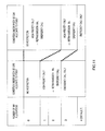
- FIG.2 suppose signatures classified by signature IDs 1 to K (region (A)) are signatures allocated by a network side to a UE and K+1 to N (region (B)) are signatures the UE allocates to itself.
- Signature sequence allocation control section 102 acquires an identifier (UE ID) of a UE, which becomes a paging target from a higher layer (not shown), and also reads a signature ID from signature table storage section 101 and allocates the read signature ID to the UE which becomes the paging target.
- Paging information processing section 103 is provided with paging information generating section 104, coding section 105 and modulation section 106.
- Paging information generating section 104 includes the signature ID outputted from signature sequence allocation control section 102, RA slot information (slot number to which RA channel is allocated) and paging control information (UE ID and other information reported through paging) inputted from a higher layer (not shown), and generates a paging channel (downlink control channel) as shown in FIG.3 .
- the paging channel generated is outputted to coding section 105.
- Coding section 105 encodes the paging channel outputted from paging information generating section 104 and modulation section 106 modulates the encoded paging channel under a modulation scheme such as BPSK and QPSK.
- the modulated paging channel is outputted to multiplexing section 110.
- DL data transmission processing section 107 is provided with coding section 108 and modulation section 109 and performs transmission processing on the DL transmission data.
- Coding section 108 encodes the DL transmission data and modulation section 109 modulates the encoded DL transmission data under a modulation scheme such as BPSK and QPSK and outputs the modulated DL transmission data to multiplexing section 110.
- Multiplexing section 110 performs time multiplexing, frequency multiplexing, space multiplexing or code multiplexing on the paging channel outputted from modulation section 106 and DL transmission data outputted from modulation section 109 and outputs the multiplexed signal to transmission RF section 111.
- Transmission RF section 111 applies predetermined radio transmission processing such as D/A conversion, filtering and up-conversion to the multiplexed signal outputted from multiplexing section 110 and transmits the signal subjected to the radio transmission processing from antenna 112.
- predetermined radio transmission processing such as D/A conversion, filtering and up-conversion to the multiplexed signal outputted from multiplexing section 110 and transmits the signal subjected to the radio transmission processing from antenna 112.
- Reception RF section 113 applies predetermined radio reception processing such as down-conversion and A/D conversion to the signal received via antenna 112 and outputs the signal subjected to the radio reception processing to demultiplexing section 114.
- Demultiplexing section 114 separates the signal outputted from reception RF section 113 into an RA slot and a UL data slot and outputs the separated RA slot to signature sequence detection section 115 and the UL data slot to demodulation section 117 of UL data reception processing section 116 respectively.
- Signature sequence detection section 115 performs preamble waveform detection processing such as correlation processing using the signatures stored in signature table storage section 101 on the RA slot outputted from demultiplexing section 114 and detects whether or not the signature sequence has been transmitted.
- the detection result (RA burst detection information) is outputted to a higher layer (not shown).
- UL data reception processing section 116 is provided with demodulation section 117 and decoding section 118 and performs reception processing on the UL data.
- Demodulation section 117 corrects distortion of the channel response of the UL data outputted from demultiplexing section 114, makes a signal point decision by a hard decision or soft decision depending on the modulation scheme and decoding section 118 performs error correcting processing about the result of the signal point decision by demodulation section 117 and outputs the UL received data.
- FIG.4 is a block diagram showing a configuration of terminal station apparatus 150 according to Embodiment 1 of the present invention.
- reception RF section 152 receives a signal transmitted from the BS shown in FIG.1 via antenna 151 and applies predetermined radio reception processing such as down-conversion and A/D conversion to the received signal and outputs the signal subjected to the radio reception processing to demultiplexing section 153.
- Demultiplexing section 153 separates the paging channel and DL data included in the signal outputted from reception RF section 152 and outputs the separated DL data to demodulation section 155 of DL data reception processing section 154 and the paging channel to demodulation section 158 of paging information reception processing section 157.
- DL data reception processing section 154 is provided with demodulation section 155 and decoding section 156, and performs reception processing on the DL data.
- Demodulation section 155 corrects distortion of the channel response on the DL data outputted from demultiplexing section 153, makes a signal point decision by a hard decision or soft decision depending on the modulation scheme, and decoding section 156 performs error correcting processing on the signal point decision result from demodulation section 155 and outputs the DL received data.
- Paging information reception processing section 157 is provided with demodulation section 158, decoding section 159 and paging information processing section 160, and performs reception processing on the paging channel.
- Demodulation section 158 corrects distortion of the channel response of the paging channel outputted from demultiplexing section 153, makes a signal point decision by a hard decision or soft decision depending on the modulation scheme, and decoding section 159 performs error correcting processing on the signal point decision result of the paging channel by demodulation section 158 and outputs paging information.
- the paging information subjected to the error correcting processing is outputted to paging information processing section 160.
- Paging information processing section 160 decides whether or not the paging information has been acquired from decoding section 159 and outputs, when the paging information has been acquired, the acquired paging information to RA burst transmission control section 161. On the other hand, when the paging information has not been acquired, paging information processing section 160 reports the fact to RA burst transmission control section 161.
- RA burst transmission control section 161 decides whether or not the paging information outputted from paging information processing section 160 is directed to terminal station apparatus 150.
- RA burst transmission control section 161 outputs the signature ID and RA slot information included in the paging information outputted from paging information processing section 160 to RA burst generating section 163.
- RA burst transmission control section 161 reports, if RA burst transmission priority information inputted from a higher layer (not shown) satisfies the condition which will be described later, that fact to RA burst generating section 163.
- RA burst transmission priority information refers to information whose communication service has a high degree of emergency or priority such as emergency communication, a service with a stringent delay requirement (e.g., VoIP, video streaming, gaming), retransmission RACH (which has higher priority as the number of retransmissions increases) and high service fee. Details of RA burst transmission control section 161 will be described later.
- Signature table storage section 162 stores a signature table held by signature table storage section 101 of BS 100 shown in FIG.1 , that is, a table storing signature IDs in a one-to-one correspondence with signature sequences. As shown in FIG.2 as in the case of the signature table held by signature table storage section 101, suppose signatures classified by signature IDs 1 to K (region (A)) are signatures allocated by the network side to UE150 and K+1 to N (region (B)) are signatures allocated by UE 150.
- RA burst generating section 163 reads the signature sequence corresponding to the signature ID outputted from RA burst transmission control section 161 from signature table storage section 162, generates an RA burst by including the read signature sequence and outputs the generated RA burst to multiplexing section 167.
- UL data transmission processing section 164 is provided with coding section 165 and modulation section 166, and performs transmission processing on UL transmission data.
- Coding section 165 encodes the UL transmission data and modulation section 166 modulates the encoded UL transmission data under a modulation scheme such as BPSK and QPSK and outputs the modulated UL transmission data to multiplexing section 167.
- Multiplexing section 167 multiplexes the RA burst outputted from RA burst generating section 163 and the UL transmission data outputted from modulation section 166, and outputs the multiplexed signal to transmission RF section 168.
- Transmission RF section 168 applies predetermined radio transmission processing such as D/A conversion, filtering and up-conversion to the multiplexed signal outputted from multiplexing section 167 and transmits the signal subjected to the radio transmission processing from antenna 151.
- predetermined radio transmission processing such as D/A conversion, filtering and up-conversion to the multiplexed signal outputted from multiplexing section 167 and transmits the signal subjected to the radio transmission processing from antenna 151.
- RA burst transmission control section 161 acquires the paging information from paging information processing section 160.
- RA burst transmission control section 161 decides whether or not a UE ID included in the acquired paging information indicates terminal station apparatus 150, moves to ST203 when the UE ID indicates terminal station apparatus 150 or moves to ST204 when the UE ID does not indicate terminal station apparatus 150.
- the signature ID and RA slot information are outputted to RA burst generating section 163.
- the UE refers to a condition under which the UE can allocate a signature to itself based on RA burst transmission priority information (or reason for transmission of RACH) inputted from a higher layer and the number of signatures allocated by the network side to other UEs and decides whether or not it is possible to transmit the RA burst.
- the number of signatures allocated by the network side to the other UEs is the same as the number of UE IDs included in the paging information and can thereby be acquired from this number of UE IDs.
- the UE side determines the signature ID from among the signatures (region (B) shown in FIG.2 ) allocated by the UE to itself according to a predetermined selection rule.
- a predetermined selection rule For example, a method of randomly determining one signature from among available signatures is generally used as the predetermined selection rule.
- the signature ID and RA slot information determined in ST205 are outputted to RA burst generating section 163.
- the network side assumes that all signatures allocatable to the UEs have been allocated, determines whether or not it is possible to transmit the RA burst, and can thereby perform control so as to prevent congestion of RA burst transmission to the RA slot.
- the UE may allocate a signature allocated to none of the other UEs by the network side to itself. In this way, the number of signatures allocatable by the UE to itself increases and the collision rate of RACH can thereby be reduced.
- RA burst transmission control section 161 of UE 150 shown in FIG.4 decides whether or not it is possible to allocate a signature to itself based on the conditions shown in FIG.6 .
- BS 100 acquires user data directed to UE 150 from a higher layer. Since a connection with UE 150 has not been established yet, BS 100 temporarily holds the acquired user data.
- one signature is selected from region (A) (see FIG.2 ) of the signature table held by signature table storage section 101 of BS 100 and the selected signature is allocated to UE 150.
- the paging information including the UE ID of UE 150, ID of the signature allocated to UE 150 and RA slot information is reported to UE 150 using a downlink control channel (e.g., paging channel).
- a downlink control channel e.g., paging channel
- UE 150 having received the paging information acquires the UE ID, allocated signature ID and RA slot included in the paging information.
- the signature corresponding to the acquired signature ID is read from the same signature table as that of BS 100 and RA burst transmission is carried out using the acquired RA slot in ST305.
- BS 100 when BS 100 having received the RA burst detects a preamble corresponding to the signature ID included in the paging information out of the received RA burst in ST303, BS 100 carries out transmission/reception of information necessary to perform user data transmission to/from UE 150 such as reporting ACK in response to the RA burst, uplink transmission start timing control information (time alignment information) and temporary UE ID (equivalent to C-RNTI in WCDMA) used for a band allocation report or the like.
- uplink transmission start timing control information time alignment information
- temporary UE ID equivalent to C-RNTI in WCDMA
- band allocation and transmission/reception of user data are carried out between BS 100 and UE 150.
- Embodiment 1 when the UE sets a condition under which the UE can allocate a signature to itself according to the number of signatures allocated by the network side to the other UE, the UE can select a signature not allocated on the network side according to a selection rule (e.g., random selection), and can thereby reduce the collision rate of RACH. Furthermore, when the UE sets the condition under which a signature can be allocated to itself within a range in which power of mutual interference between signatures satisfies allowable interference power, it is possible to suppress increases in mutual interference power between signatures and thereby improve the RACH detection characteristics.
- a selection rule e.g., random selection
- a method of explicitly transmitting a signature ID as control information as shown in FIG.3 may be used as the method of reporting a signature ID, and when a plurality of pieces of paging information simultaneously generated are reported collectively, the sequence of UE IDs and sequence of signature IDs may be set beforehand as shown in FIG.8 and it is thereby possible to prevent an increase of control information for reporting signature IDs. Furthermore, the same applies to a case where RA slots for paging are reported with paging information.
- Embodiment 2 of the present invention Configurations of a base station apparatus and a terminal station apparatus according to Embodiment 2 of the present invention are the same as those of Embodiment 1 shown in FIG.1 and FIG.4 and only part of the functions are different, and therefore only different functions will be explained using FIG.1 and FIG.4 and overlapping explanations will be omitted.
- FIG.9 shows conditions under which a UE according to Embodiment 2 of the present invention can allocate a signature to itself.
- the network side alleviates the conditions under which the UE can allocate a signature to itself in order of an RA slot (initial RA slot) including the signature allocated by the network side to the UE, next RA slot and next but one RA slot.
- RA slot initial RA slot
- the next RA slot when the number of signatures allocated by the network to the UE is 3 and 4, only UEs with a service of high priority such as retransmission RA or emergency communication (emergency call) can allocate signatures to themselves.
- a service of high priority such as retransmission RA or emergency communication (emergency call)
- next but one RA slot when the number of signatures allocated by the network side to the UE corresponds to all 0 to 4, there is no restriction on conditions and all UEs can allocate signatures to themselves.
- the UE controls the expected value of the number of RAs using the signature allocated to the UE itself based on a reception success rate (retransmission rate) per number of signatures allocated by the network side to the UE and the expected value of the number of retransmission RAs in the next RA slot obtained from the number of retransmissions of RA burst.
- retransmission rate reception success rate
- FIG.10 shows transition in the number of transmission RA bursts included in RA slot#1 (initial RA slot) and following RA slot#2 (next RA slot) and #3 (next but one RA slot) for which the network side has allocated signature to the UE.
- RA slot#1 initial RA slot
- RA slot#2 next RA slot
- #3 next but one RA slot
- the number of signatures allocated by the UE to itself is 1.
- three of the RAs using signatures allocated by the network side to the UE have succeeded in reception and one has failed in reception.
- RA slot#2 suppose the RA having failed in reception in RA slot#1 is retransmitted and the UE assumes the remaining four RAs as signatures to be allocated to itself. Furthermore, in RA slot#3, suppose the UE assumes all five RAs that can be transmitted in this RA slot as signatures to be allocated to itself.
- Embodiment 2 alleviate the conditions under which the UE can allocate a signature to itself, and thereby allows even a UE which does not correspond to the conditions in the following RA slots to allocate a signature to itself and improve the utilization efficiency of the RA slots.
- Configurations of a base station apparatus and a terminal station apparatus according to Embodiment 3 of the present invention are the same as the configurations of Embodiment 1 shown in FIG.1 and FIG.4 , and only part of the functions are different, and therefore only different functions will be explained with reference to FIG.1 and FIG.4 and overlapping explanations will be omitted.
- FIG. 11 shows conditions under which a UE according to Embodiment 3 of the present invention can allocate a signature to itself.
- the conditions of Embodiment 1 shown in FIG.6 are shown on the left side of FIG.11 for comparison.
- the network side allocates signatures to a UE in order starting with a signature sequence with high orthogonality (with small inter-code interference).
- Such allocations provide a relationship between the number of signature allocations and inter-code interference as shown in FIG.12 . That is, the amount of inter-code interference increases exponentially as the number of signature allocations increases.
- FIG.13 shows a relationship between the number of signatures allocated by the network side to UEs and interference power. As shown in this figure, when the number of signatures allocated by the network side to the UE is small, since the interference power between these allocated signatures is small, the number of signatures allocated by the UE to itself can be increased.
- the network side allocates signatures to the UE starting with a signature sequence with small inter-code interference, and the UE can thereby give greater interference margin to RAs using signatures allocated by the UE to itself, and therefore the number of RAs that can be transmitted/received per RA slot can be increased.
- the network side reports signatures allocated to UEs to the UEs using paging channels, but the present invention is not limited to this and the network side may also report signatures using, for example, a downlink control channel including scheduling information or a downlink common channel including an L2/L3 control message.
- each functional block used for the explanations of the above-described embodiments is typically implemented as an LSI which is an integrated circuit. These may be integrated into a single chip individually or may be integrated into a single chip so as to include some or all functional blocks.
- LSI is used, but the term may also be “IC, " "system LSI,” “super LSI” or “ultra LSI” depending on the difference in the degree of integration.
- an integrated circuit is not limited to an LSI but can also be implemented with a dedicated circuit or a general-purpose processor. It is also possible to use an FPGA (Field Programmable Gate Array) which can be programmed or a reconfigurable processor whose connections or settings of circuit cells inside the LSI are reconfigurable after LSI manufacturing.
- FPGA Field Programmable Gate Array
- the radio transmitting apparatus and radio transmission method according to the present invention can not only reduce the RACH collision rate but also improve the RACH detection characteristics, and can be applied to a mobile communication system and so on.
Landscapes
- Engineering & Computer Science (AREA)
- Computer Networks & Wireless Communication (AREA)
- Signal Processing (AREA)
- Mobile Radio Communication Systems (AREA)
Applications Claiming Priority (2)
| Application Number | Priority Date | Filing Date | Title |
|---|---|---|---|
| JP2006261197 | 2006-09-26 | ||
| PCT/JP2007/068661 WO2008041582A1 (en) | 2006-09-26 | 2007-09-26 | Radio transmission device and radio transmission method |
Publications (3)
| Publication Number | Publication Date |
|---|---|
| EP2068574A1 true EP2068574A1 (de) | 2009-06-10 |
| EP2068574A4 EP2068574A4 (de) | 2013-06-05 |
| EP2068574B1 EP2068574B1 (de) | 2015-03-11 |
Family
ID=39268444
Family Applications (1)
| Application Number | Title | Priority Date | Filing Date |
|---|---|---|---|
| EP07807876.3A Active EP2068574B1 (de) | 2006-09-26 | 2007-09-26 | Funkübertragungseinrichtung und funkübertragungsverfahren |
Country Status (4)
| Country | Link |
|---|---|
| US (4) | US8265025B2 (de) |
| EP (1) | EP2068574B1 (de) |
| JP (2) | JP4903213B2 (de) |
| WO (1) | WO2008041582A1 (de) |
Cited By (1)
| Publication number | Priority date | Publication date | Assignee | Title |
|---|---|---|---|---|
| EP2413657A3 (de) * | 2008-04-28 | 2012-05-23 | Fujitsu Limited | Verbindungsverarbeitungsverfahren in einem drahtlosen Kommunikationssystem, drahtlose Basisstation und drahtloses Endgerät |
Families Citing this family (12)
| Publication number | Priority date | Publication date | Assignee | Title |
|---|---|---|---|---|
| CN101883440B (zh) | 2006-10-31 | 2014-05-28 | 夏普株式会社 | 通信处理方法、通信系统、基站以及移动站 |
| JP4481316B2 (ja) * | 2007-01-09 | 2010-06-16 | 株式会社エヌ・ティ・ティ・ドコモ | ユーザ装置および送信方法 |
| KR100925333B1 (ko) * | 2008-03-14 | 2009-11-04 | 엘지전자 주식회사 | 랜덤 액세스 과정에서 상향링크 동기화를 수행하는 방법 |
| US9370021B2 (en) | 2008-07-31 | 2016-06-14 | Google Technology Holdings LLC | Interference reduction for terminals operating on neighboring bands in wireless communication systems |
| EP2418908A4 (de) * | 2009-04-07 | 2012-03-28 | Huawei Tech Co Ltd | Direktzugriffsverfahren und einrichtung dafür |
| US8520617B2 (en) | 2009-11-06 | 2013-08-27 | Motorola Mobility Llc | Interference mitigation in heterogeneous wireless communication networks |
| US8433249B2 (en) | 2009-11-06 | 2013-04-30 | Motorola Mobility Llc | Interference reduction for terminals operating in heterogeneous wireless communication networks |
| US10206181B2 (en) * | 2012-01-30 | 2019-02-12 | Texas Instruments Incorporated | Simultaneous transmission in multiple timing advance groups |
| USRE48361E1 (en) * | 2012-06-27 | 2020-12-15 | Lg Electronics Inc. | Method and terminal for random access to small cell |
| CN104519589A (zh) | 2013-09-26 | 2015-04-15 | 中兴通讯股份有限公司 | 随机接入方法和装置 |
| JP6224452B2 (ja) * | 2013-12-24 | 2017-11-01 | 京セラ株式会社 | ユーザ端末、方法、及びプロセッサ |
| CN109690984B (zh) * | 2016-09-29 | 2021-10-08 | 英特尔公司 | 通信方法和系统 |
Family Cites Families (30)
| Publication number | Priority date | Publication date | Assignee | Title |
|---|---|---|---|---|
| JP3231575B2 (ja) * | 1995-04-18 | 2001-11-26 | 三菱電機株式会社 | 無線データ伝送装置 |
| WO2000019761A1 (fr) * | 1998-09-30 | 2000-04-06 | Mitsubishi Denki Kabushiki Kaisha | Techniques permettant de detecter et d'eviter les interferences |
| EP2306662B1 (de) * | 1998-10-05 | 2014-08-27 | Sony Deutschland Gmbh | Prioritätsschema für Direkt-Zugriffskanal |
| US6567482B1 (en) * | 1999-03-05 | 2003-05-20 | Telefonaktiebolaget Lm Ericsson (Publ) | Method and apparatus for efficient synchronization in spread spectrum communications |
| GB9906198D0 (en) * | 1999-03-18 | 1999-05-12 | Lucent Technologies Inc | Improved random access channel |
| DE10008653A1 (de) * | 2000-02-24 | 2001-09-06 | Siemens Ag | Verbesserungen an einem Funkkommunikationssystem |
| US7079507B2 (en) * | 2000-02-25 | 2006-07-18 | Nokia Corporation | Method and apparatus for common packet channel assignment |
| US6778835B2 (en) * | 2000-03-18 | 2004-08-17 | Lg Electronics Inc. | Method for allocating physical channel of mobile communication system and communication method using the same |
| ES2286964T3 (es) * | 2000-04-04 | 2007-12-16 | Sony Deutschland Gmbh | Cambio de clase de servicio de acceso en una canal aleatorio, provocado por un evento. |
| ATE381865T1 (de) * | 2000-04-04 | 2008-01-15 | Sony Deutschland Gmbh | Verfahren zur priorisierung von nutzern, die auf einen gemeinsamen kommunikationskanal auf eine zufällige weise zugreifen |
| EP1186125B1 (de) * | 2000-04-10 | 2006-08-16 | Samsung Electronics Co., Ltd. | Verfahren zur messung der verwirrungsrate eines gemeinsames paketkanals in einem cdma-übertragungssystem |
| JP3735056B2 (ja) * | 2001-10-09 | 2006-01-11 | 株式会社日立国際電気 | Cdma無線基地局 |
| US7239621B2 (en) * | 2001-12-04 | 2007-07-03 | Telefonaktiebolaget Lm Ericsson (Publ) | Physical channel relation system/method for use in cellular telecommunications network |
| US7558314B2 (en) * | 2002-09-23 | 2009-07-07 | Telefonaktiebolaget L M Ericsson (Publ) | Method and device for detection of a UMTS signal |
| KR20040029253A (ko) * | 2002-09-30 | 2004-04-06 | 삼성전자주식회사 | 직교 주파수 분할 다중 방식을 사용하는 통신시스템에서프리앰블 시퀀스 생성 장치 및 방법 |
| US7366202B2 (en) * | 2003-12-08 | 2008-04-29 | Colubris Networks, Inc. | System and method for interference mitigation for wireless communication |
| US7643454B2 (en) * | 2004-06-07 | 2010-01-05 | Alcatel-Lucent Usa Inc. | Methods of avoiding multiple detections of random access channel preamble in wireless communication systems |
| BRPI0615235A2 (pt) * | 2005-09-08 | 2011-05-10 | Lg Electronics Inc | mÉtodo e protocolo para manipular tentativas de acesso para sistemas de comunicaÇço |
| WO2007066883A1 (en) * | 2005-10-31 | 2007-06-14 | Lg Electronics Inc. | Method of transmitting a measurement report in a wireless mobile communications system |
| KR100962765B1 (ko) * | 2005-10-31 | 2010-06-10 | 엘지전자 주식회사 | 이동통신 시스템에서의 상향링크 무선자원 할당방법 |
| JP4885978B2 (ja) * | 2005-12-23 | 2012-02-29 | エルジー エレクトロニクス インコーポレイティド | E−utraシステムにおける非同期、同期、及び同期待ち通信のための方法、並びに手順 |
| KR101187076B1 (ko) * | 2006-01-05 | 2012-09-27 | 엘지전자 주식회사 | 이동 통신 시스템에 있어서 신호 전송 방법 |
| USRE43949E1 (en) * | 2006-01-05 | 2013-01-29 | Lg Electronics Inc. | Allocating radio resources in mobile communications system |
| US8000305B2 (en) * | 2006-01-17 | 2011-08-16 | Motorola Mobility, Inc. | Preamble sequencing for random access channel in a communication system |
| RU2407155C2 (ru) * | 2006-01-20 | 2010-12-20 | Нокиа Корпорейшн | Процедура произвольного доступа с увеличенной зоной действия |
| US20070211671A1 (en) * | 2006-03-09 | 2007-09-13 | Interdigital Technology Corporation | Method and apparatus for a flexible preamble and efficient transmission thereof |
| US8098745B2 (en) * | 2006-03-27 | 2012-01-17 | Texas Instruments Incorporated | Random access structure for wireless networks |
| JP2007266733A (ja) | 2006-03-27 | 2007-10-11 | Nec Corp | ランダムアクセス方法と無線端末並びに無線通信システム |
| US8559382B2 (en) * | 2007-03-15 | 2013-10-15 | Electronics And Telecommunications Research Institute | Preamble allocation method and random access method in mobile communication system |
| JP5070093B2 (ja) * | 2008-03-06 | 2012-11-07 | パナソニック株式会社 | 無線基地局装置、無線端末装置、無線中継局装置、送信パワー制御方法、無線通信中継方法および無線通信システム |
-
2007
- 2007-09-26 JP JP2008537488A patent/JP4903213B2/ja active Active
- 2007-09-26 EP EP07807876.3A patent/EP2068574B1/de active Active
- 2007-09-26 US US12/442,475 patent/US8265025B2/en active Active
- 2007-09-26 WO PCT/JP2007/068661 patent/WO2008041582A1/ja active Application Filing
-
2011
- 2011-11-10 JP JP2011246334A patent/JP2012080556A/ja active Pending
-
2012
- 2012-08-07 US US13/568,853 patent/US8824409B2/en active Active
-
2014
- 2014-06-12 US US14/303,351 patent/US9313808B2/en active Active
-
2016
- 2016-02-29 US US15/056,926 patent/US9775176B2/en active Active
Non-Patent Citations (5)
| Title |
|---|
| 3GPP DRAFT; R2-052769, 3RD GENERATION PARTNERSHIP PROJECT (3GPP), MOBILE COMPETENCE CENTRE ; 650, ROUTE DES LUCIOLES ; F-06921 SOPHIA-ANTIPOLIS CEDEX ; FRANCE, vol. RAN WG2, no. Seoul, Korea; 20051102, 2 November 2005 (2005-11-02), XP050129766, [retrieved on 2005-11-02] * |
| 3GPP DRAFT; R2-061552-LTE_INITIAL_R2, 3RD GENERATION PARTNERSHIP PROJECT (3GPP), MOBILE COMPETENCE CENTRE ; 650, ROUTE DES LUCIOLES ; F-06921 SOPHIA-ANTIPOLIS CEDEX ; FRANCE, vol. RAN WG2, no. Shanghai, China; 20060515, 15 May 2006 (2006-05-15), XP050131457, [retrieved on 2006-05-15] * |
| PANASONIC: "Random access procedure for E-UTRA", 3GPP DRAFT; R1-061765, 3RD GENERATION PARTNERSHIP PROJECT (3GPP), MOBILE COMPETENCE CENTRE ; 650, ROUTE DES LUCIOLES ; F-06921 SOPHIA-ANTIPOLIS CEDEX ; FRANCE, vol. RAN WG1, no. Cannes, France; 20060620, 20 June 2006 (2006-06-20), XP050111586, [retrieved on 2006-06-20] * |
| PHILIPS: "Signalling for Random Access for LTE", 3GPP DRAFT; R2-060016, 3RD GENERATION PARTNERSHIP PROJECT (3GPP), MOBILE COMPETENCE CENTRE ; 650, ROUTE DES LUCIOLES ; F-06921 SOPHIA-ANTIPOLIS CEDEX ; FRANCE, vol. RAN WG2, no. Sophia Antipolis, France; 20060105, 5 January 2006 (2006-01-05), XP050130185, [retrieved on 2006-01-05] * |
| See also references of WO2008041582A1 * |
Cited By (2)
| Publication number | Priority date | Publication date | Assignee | Title |
|---|---|---|---|---|
| EP2413657A3 (de) * | 2008-04-28 | 2012-05-23 | Fujitsu Limited | Verbindungsverarbeitungsverfahren in einem drahtlosen Kommunikationssystem, drahtlose Basisstation und drahtloses Endgerät |
| EP2413656A3 (de) * | 2008-04-28 | 2012-05-23 | Fujitsu Limited | Verbindungsverarbeitungsverfahren in einem drahtlosen Kommunikationssystem, drahtlose Basisstation und drahtloses Endgerät |
Also Published As
| Publication number | Publication date |
|---|---|
| US20140293923A1 (en) | 2014-10-02 |
| US20160183306A1 (en) | 2016-06-23 |
| US8824409B2 (en) | 2014-09-02 |
| US8265025B2 (en) | 2012-09-11 |
| JPWO2008041582A1 (ja) | 2010-02-04 |
| EP2068574B1 (de) | 2015-03-11 |
| JP4903213B2 (ja) | 2012-03-28 |
| EP2068574A4 (de) | 2013-06-05 |
| US20100027484A1 (en) | 2010-02-04 |
| US20120300734A1 (en) | 2012-11-29 |
| JP2012080556A (ja) | 2012-04-19 |
| US9775176B2 (en) | 2017-09-26 |
| US9313808B2 (en) | 2016-04-12 |
| WO2008041582A1 (en) | 2008-04-10 |
Similar Documents
| Publication | Publication Date | Title |
|---|---|---|
| US9775176B2 (en) | Radio transmission device and radio transmission method | |
| US11638241B2 (en) | Communication system, mobile station, base station, response decision method, resource configuration decision method, and program | |
| JP4964241B2 (ja) | 無線送信装置及び無線送信方法 | |
| EP1949566B1 (de) | Direktzugriffs-kanalsprung für frequenzmultiplex-zugangssysteme | |
| US10299292B2 (en) | Method and device for detecting RACH preamble collision caused by multi-path channel in wireless communication system | |
| US9100955B2 (en) | Terminal, base station and signal transmission control method | |
| US8422532B2 (en) | Radio communication device and response signal spreading method | |
| US20110051609A1 (en) | Base station apparatus, mobile station apparatus, and mobile station control method in mobile communication system | |
| CN110932834A (zh) | 终端、基站、通信方法以及集成电路 | |
| US10609734B2 (en) | Method and apparatus for detecting RACH preamble on basis of plurality of zero-correlation zones in wireless communication system |
Legal Events
| Date | Code | Title | Description |
|---|---|---|---|
| PUAI | Public reference made under article 153(3) epc to a published international application that has entered the european phase |
Free format text: ORIGINAL CODE: 0009012 |
|
| 17P | Request for examination filed |
Effective date: 20090320 |
|
| AK | Designated contracting states |
Kind code of ref document: A1 Designated state(s): AT BE BG CH CY CZ DE DK EE ES FI FR GB GR HU IE IS IT LI LT LU LV MC MT NL PL PT RO SE SI SK TR |
|
| AX | Request for extension of the european patent |
Extension state: AL BA HR MK RS |
|
| RIC1 | Information provided on ipc code assigned before grant |
Ipc: H04J 3/16 20060101ALI20090518BHEP Ipc: H04W 4/00 20090101ALI20090518BHEP Ipc: H04W 16/00 20090101AFI20090518BHEP |
|
| DAX | Request for extension of the european patent (deleted) | ||
| A4 | Supplementary search report drawn up and despatched |
Effective date: 20130507 |
|
| RIC1 | Information provided on ipc code assigned before grant |
Ipc: H04W 74/08 20090101AFI20130429BHEP |
|
| RAP1 | Party data changed (applicant data changed or rights of an application transferred) |
Owner name: PANASONIC INTELLECTUAL PROPERTY CORPORATION OF AME |
|
| REG | Reference to a national code |
Ref country code: DE Ref legal event code: R079 Ref document number: 602007040593 Country of ref document: DE Free format text: PREVIOUS MAIN CLASS: H04W0016000000 Ipc: H04W0074080000 |
|
| GRAP | Despatch of communication of intention to grant a patent |
Free format text: ORIGINAL CODE: EPIDOSNIGR1 |
|
| RIC1 | Information provided on ipc code assigned before grant |
Ipc: H04W 74/08 20090101AFI20140910BHEP |
|
| INTG | Intention to grant announced |
Effective date: 20141008 |
|
| GRAS | Grant fee paid |
Free format text: ORIGINAL CODE: EPIDOSNIGR3 |
|
| GRAA | (expected) grant |
Free format text: ORIGINAL CODE: 0009210 |
|
| AK | Designated contracting states |
Kind code of ref document: B1 Designated state(s): AT BE BG CH CY CZ DE DK EE ES FI FR GB GR HU IE IS IT LI LT LU LV MC MT NL PL PT RO SE SI SK TR |
|
| REG | Reference to a national code |
Ref country code: GB Ref legal event code: FG4D |
|
| REG | Reference to a national code |
Ref country code: CH Ref legal event code: EP |
|
| REG | Reference to a national code |
Ref country code: IE Ref legal event code: FG4D |
|
| REG | Reference to a national code |
Ref country code: AT Ref legal event code: REF Ref document number: 715907 Country of ref document: AT Kind code of ref document: T Effective date: 20150415 |
|
| REG | Reference to a national code |
Ref country code: DE Ref legal event code: R096 Ref document number: 602007040593 Country of ref document: DE Effective date: 20150423 |
|
| REG | Reference to a national code |
Ref country code: NL Ref legal event code: VDEP Effective date: 20150311 |
|
| REG | Reference to a national code |
Ref country code: NL Ref legal event code: VDEP Effective date: 20150311 |
|
| PG25 | Lapsed in a contracting state [announced via postgrant information from national office to epo] |
Ref country code: SE Free format text: LAPSE BECAUSE OF FAILURE TO SUBMIT A TRANSLATION OF THE DESCRIPTION OR TO PAY THE FEE WITHIN THE PRESCRIBED TIME-LIMIT Effective date: 20150311 Ref country code: FI Free format text: LAPSE BECAUSE OF FAILURE TO SUBMIT A TRANSLATION OF THE DESCRIPTION OR TO PAY THE FEE WITHIN THE PRESCRIBED TIME-LIMIT Effective date: 20150311 Ref country code: LT Free format text: LAPSE BECAUSE OF FAILURE TO SUBMIT A TRANSLATION OF THE DESCRIPTION OR TO PAY THE FEE WITHIN THE PRESCRIBED TIME-LIMIT Effective date: 20150311 Ref country code: ES Free format text: LAPSE BECAUSE OF FAILURE TO SUBMIT A TRANSLATION OF THE DESCRIPTION OR TO PAY THE FEE WITHIN THE PRESCRIBED TIME-LIMIT Effective date: 20150311 |
|
| REG | Reference to a national code |
Ref country code: AT Ref legal event code: MK05 Ref document number: 715907 Country of ref document: AT Kind code of ref document: T Effective date: 20150311 |
|
| REG | Reference to a national code |
Ref country code: LT Ref legal event code: MG4D |
|
| PG25 | Lapsed in a contracting state [announced via postgrant information from national office to epo] |
Ref country code: LV Free format text: LAPSE BECAUSE OF FAILURE TO SUBMIT A TRANSLATION OF THE DESCRIPTION OR TO PAY THE FEE WITHIN THE PRESCRIBED TIME-LIMIT Effective date: 20150311 Ref country code: GR Free format text: LAPSE BECAUSE OF FAILURE TO SUBMIT A TRANSLATION OF THE DESCRIPTION OR TO PAY THE FEE WITHIN THE PRESCRIBED TIME-LIMIT Effective date: 20150612 |
|
| PG25 | Lapsed in a contracting state [announced via postgrant information from national office to epo] |
Ref country code: NL Free format text: LAPSE BECAUSE OF FAILURE TO SUBMIT A TRANSLATION OF THE DESCRIPTION OR TO PAY THE FEE WITHIN THE PRESCRIBED TIME-LIMIT Effective date: 20150311 |
|
| PG25 | Lapsed in a contracting state [announced via postgrant information from national office to epo] |
Ref country code: CZ Free format text: LAPSE BECAUSE OF FAILURE TO SUBMIT A TRANSLATION OF THE DESCRIPTION OR TO PAY THE FEE WITHIN THE PRESCRIBED TIME-LIMIT Effective date: 20150311 Ref country code: EE Free format text: LAPSE BECAUSE OF FAILURE TO SUBMIT A TRANSLATION OF THE DESCRIPTION OR TO PAY THE FEE WITHIN THE PRESCRIBED TIME-LIMIT Effective date: 20150311 Ref country code: PT Free format text: LAPSE BECAUSE OF FAILURE TO SUBMIT A TRANSLATION OF THE DESCRIPTION OR TO PAY THE FEE WITHIN THE PRESCRIBED TIME-LIMIT Effective date: 20150713 Ref country code: SK Free format text: LAPSE BECAUSE OF FAILURE TO SUBMIT A TRANSLATION OF THE DESCRIPTION OR TO PAY THE FEE WITHIN THE PRESCRIBED TIME-LIMIT Effective date: 20150311 Ref country code: RO Free format text: LAPSE BECAUSE OF FAILURE TO SUBMIT A TRANSLATION OF THE DESCRIPTION OR TO PAY THE FEE WITHIN THE PRESCRIBED TIME-LIMIT Effective date: 20150311 |
|
| PG25 | Lapsed in a contracting state [announced via postgrant information from national office to epo] |
Ref country code: IS Free format text: LAPSE BECAUSE OF FAILURE TO SUBMIT A TRANSLATION OF THE DESCRIPTION OR TO PAY THE FEE WITHIN THE PRESCRIBED TIME-LIMIT Effective date: 20150711 Ref country code: PL Free format text: LAPSE BECAUSE OF FAILURE TO SUBMIT A TRANSLATION OF THE DESCRIPTION OR TO PAY THE FEE WITHIN THE PRESCRIBED TIME-LIMIT Effective date: 20150311 Ref country code: AT Free format text: LAPSE BECAUSE OF FAILURE TO SUBMIT A TRANSLATION OF THE DESCRIPTION OR TO PAY THE FEE WITHIN THE PRESCRIBED TIME-LIMIT Effective date: 20150311 |
|
| REG | Reference to a national code |
Ref country code: DE Ref legal event code: R097 Ref document number: 602007040593 Country of ref document: DE |
|
| PG25 | Lapsed in a contracting state [announced via postgrant information from national office to epo] |
Ref country code: IT Free format text: LAPSE BECAUSE OF FAILURE TO SUBMIT A TRANSLATION OF THE DESCRIPTION OR TO PAY THE FEE WITHIN THE PRESCRIBED TIME-LIMIT Effective date: 20150311 |
|
| PLBE | No opposition filed within time limit |
Free format text: ORIGINAL CODE: 0009261 |
|
| STAA | Information on the status of an ep patent application or granted ep patent |
Free format text: STATUS: NO OPPOSITION FILED WITHIN TIME LIMIT |
|
| PG25 | Lapsed in a contracting state [announced via postgrant information from national office to epo] |
Ref country code: DK Free format text: LAPSE BECAUSE OF FAILURE TO SUBMIT A TRANSLATION OF THE DESCRIPTION OR TO PAY THE FEE WITHIN THE PRESCRIBED TIME-LIMIT Effective date: 20150311 |
|
| 26N | No opposition filed |
Effective date: 20151214 |
|
| PG25 | Lapsed in a contracting state [announced via postgrant information from national office to epo] |
Ref country code: SI Free format text: LAPSE BECAUSE OF FAILURE TO SUBMIT A TRANSLATION OF THE DESCRIPTION OR TO PAY THE FEE WITHIN THE PRESCRIBED TIME-LIMIT Effective date: 20150311 |
|
| PG25 | Lapsed in a contracting state [announced via postgrant information from national office to epo] |
Ref country code: LU Free format text: LAPSE BECAUSE OF FAILURE TO SUBMIT A TRANSLATION OF THE DESCRIPTION OR TO PAY THE FEE WITHIN THE PRESCRIBED TIME-LIMIT Effective date: 20150926 Ref country code: MC Free format text: LAPSE BECAUSE OF FAILURE TO SUBMIT A TRANSLATION OF THE DESCRIPTION OR TO PAY THE FEE WITHIN THE PRESCRIBED TIME-LIMIT Effective date: 20150311 |
|
| REG | Reference to a national code |
Ref country code: CH Ref legal event code: PL |
|
| GBPC | Gb: european patent ceased through non-payment of renewal fee |
Effective date: 20150926 |
|
| REG | Reference to a national code |
Ref country code: IE Ref legal event code: MM4A |
|
| REG | Reference to a national code |
Ref country code: FR Ref legal event code: ST Effective date: 20160531 |
|
| PG25 | Lapsed in a contracting state [announced via postgrant information from national office to epo] |
Ref country code: IE Free format text: LAPSE BECAUSE OF NON-PAYMENT OF DUE FEES Effective date: 20150926 Ref country code: CH Free format text: LAPSE BECAUSE OF NON-PAYMENT OF DUE FEES Effective date: 20150930 Ref country code: LI Free format text: LAPSE BECAUSE OF NON-PAYMENT OF DUE FEES Effective date: 20150930 Ref country code: GB Free format text: LAPSE BECAUSE OF NON-PAYMENT OF DUE FEES Effective date: 20150926 |
|
| PG25 | Lapsed in a contracting state [announced via postgrant information from national office to epo] |
Ref country code: FR Free format text: LAPSE BECAUSE OF NON-PAYMENT OF DUE FEES Effective date: 20150930 Ref country code: BE Free format text: LAPSE BECAUSE OF FAILURE TO SUBMIT A TRANSLATION OF THE DESCRIPTION OR TO PAY THE FEE WITHIN THE PRESCRIBED TIME-LIMIT Effective date: 20150311 |
|
| PG25 | Lapsed in a contracting state [announced via postgrant information from national office to epo] |
Ref country code: MT Free format text: LAPSE BECAUSE OF FAILURE TO SUBMIT A TRANSLATION OF THE DESCRIPTION OR TO PAY THE FEE WITHIN THE PRESCRIBED TIME-LIMIT Effective date: 20150311 |
|
| PG25 | Lapsed in a contracting state [announced via postgrant information from national office to epo] |
Ref country code: BG Free format text: LAPSE BECAUSE OF FAILURE TO SUBMIT A TRANSLATION OF THE DESCRIPTION OR TO PAY THE FEE WITHIN THE PRESCRIBED TIME-LIMIT Effective date: 20150311 Ref country code: HU Free format text: LAPSE BECAUSE OF FAILURE TO SUBMIT A TRANSLATION OF THE DESCRIPTION OR TO PAY THE FEE WITHIN THE PRESCRIBED TIME-LIMIT; INVALID AB INITIO Effective date: 20070926 |
|
| PG25 | Lapsed in a contracting state [announced via postgrant information from national office to epo] |
Ref country code: CY Free format text: LAPSE BECAUSE OF FAILURE TO SUBMIT A TRANSLATION OF THE DESCRIPTION OR TO PAY THE FEE WITHIN THE PRESCRIBED TIME-LIMIT Effective date: 20150311 |
|
| PG25 | Lapsed in a contracting state [announced via postgrant information from national office to epo] |
Ref country code: TR Free format text: LAPSE BECAUSE OF FAILURE TO SUBMIT A TRANSLATION OF THE DESCRIPTION OR TO PAY THE FEE WITHIN THE PRESCRIBED TIME-LIMIT Effective date: 20150311 |
|
| P01 | Opt-out of the competence of the unified patent court (upc) registered |
Effective date: 20230509 |
|
| PGFP | Annual fee paid to national office [announced via postgrant information from national office to epo] |
Ref country code: DE Payment date: 20230920 Year of fee payment: 17 |