EP2068568A2 - Bildsignalumwandlungsvorrichtung und Bildanzeigevorrichtung - Google Patents
Bildsignalumwandlungsvorrichtung und Bildanzeigevorrichtung Download PDFInfo
- Publication number
- EP2068568A2 EP2068568A2 EP08020836A EP08020836A EP2068568A2 EP 2068568 A2 EP2068568 A2 EP 2068568A2 EP 08020836 A EP08020836 A EP 08020836A EP 08020836 A EP08020836 A EP 08020836A EP 2068568 A2 EP2068568 A2 EP 2068568A2
- Authority
- EP
- European Patent Office
- Prior art keywords
- component light
- light
- input signal
- image
- green
- Prior art date
- Legal status (The legal status is an assumption and is not a legal conclusion. Google has not performed a legal analysis and makes no representation as to the accuracy of the status listed.)
- Withdrawn
Links
Images


Classifications
-
- H—ELECTRICITY
- H04—ELECTRIC COMMUNICATION TECHNIQUE
- H04N—PICTORIAL COMMUNICATION, e.g. TELEVISION
- H04N9/00—Details of colour television systems
- H04N9/64—Circuits for processing colour signals
- H04N9/68—Circuits for processing colour signals for controlling the amplitude of colour signals, e.g. automatic chroma control circuits
-
- H—ELECTRICITY
- H04—ELECTRIC COMMUNICATION TECHNIQUE
- H04N—PICTORIAL COMMUNICATION, e.g. TELEVISION
- H04N9/00—Details of colour television systems
- H04N9/12—Picture reproducers
- H04N9/31—Projection devices for colour picture display, e.g. using electronic spatial light modulators [ESLM]
- H04N9/3179—Video signal processing therefor
- H04N9/3182—Colour adjustment, e.g. white balance, shading or gamut
Definitions
- the present invention relates to an image signal converting apparatus and an image display apparatus, each generating a red output signal, a green output signal, and a blue output signal based on a red input signal, a green input signal, and a blue input signal, respectively.
- a three-panel image display apparatus has heretofore been widely known which includes a red light imager modulating red component light, a green light imager modulating green component light, and a blue light imager modulating blue component light.
- such an image display apparatus may use a method of separating the white light so as to preferentially increase a light amount of red component light, or to preferentially increase a light amount of green component light, or a similar method.
- a light amount of red component light is preferentially increased, a waveband of red component light is extended to the short wavelength side, so that color reproduced by the red component light becomes orange.
- a light amount of green component light is preferentially increased, a waveband of green component light is extended to the long wavelength side, so that color reproduced by the green component light becomes yellowish green. Consequently, purities of colors reproduced by red component light, green component light, and blue component light are degraded.
- a projection display apparatus intended to improve color purities has been proposed (e.g., Japanese Patent Application Publication No. 2001-186539 , in particular claim 1, [0028], Fig. 6 , and the like).
- a light amount of color component light e.g., yellow component light Ye
- a light amount of blue component light other than the red component light and the green component light is increased.
- a predetermined value is reduced from any one of a red input signal and a green input signal, and then, a predetermined value is added to a blue input signal.
- a predetermined value is added to a blue input signal.
- a first aspect of an image signal converting apparatus of the present invention is as follows.
- the image signal converting apparatus is used in an image display apparatus (a projection display apparatus) having a light source which emits light including red component light, green component light, blue component light, and fourth color component light.
- the image signal converting apparatus includes a controlling unit configured to generate an image output signal based on an image input signal.
- the image input signal includes a red input signal corresponding to the red component light, a green input signal corresponding to the green component light, and a blue input signal corresponding to the blue component light.
- the image output signal includes a red output signal corresponding to the red component light, a green output signal corresponding to the green component light, and a blue output signal corresponding to the blue component light.
- the fourth color component light is substitutable by substitution component light composed of any two of the red component light, the green component light, and the blue component light.
- the controlling unit performs, according to a light amount of the fourth color component light, subtraction processing on a subtraction target signal that is an input signal constituting a part of the image input signal and corresponding to the substitution component light, and the controlling unit generates an output signal constituting a part of the image output signal and corresponding to the substitution component light.
- the controlling unit performs subtraction processing on the subtraction target signal according to the light amount of the fourth color component light, and the controlling unit generates the output signal corresponding to the substitution component light. Therefore, it becomes possible to restrain not only the deterioration of color purity, but also the deterioration of saturation.
- the controlling unit performs addition processing on an addition target signal that is an input signal constituting a part of the image input signal and corresponding to color component light other than the substitution component light, and the controlling unit generates an output signal constituting a part of the image output signal and corresponding to the color component light other than the substitution component light.
- the image display apparatus includes: a light source configured to emit light including red component light, green component light, blue component light, and fourth color component light; a controlling unit configured to control an image output signal based on an image input signal; and an image display unit configured to display an image based on the image output signal.
- the image input signal includes a red input signal corresponding to the red component light, a green input signal corresponding to the green component light, and a blue input signal corresponding to the blue component light.
- the image output signal includes a red output signal corresponding to the red component light, a green output signal corresponding to the green component light, and a blue output signal corresponding to the blue component light.
- the fourth color component light is substitutable by substitution component light composed of any two of the red component light, the green component light, and the blue component light.
- the controlling unit performs, according to a light amount of the fourth color component light, subtraction processing on subtraction a target signal that is an input signal constituting a part of the image input signal and corresponding to the substitution component light, and the controlling unit generates an output signal constituting a part of the image output signal and corresponding to the substitution component light.
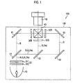
- FIG. 1 is a diagram showing a projection display apparatus 100 of the first embodiment.
- the projection display apparatus 100 includes a projection lens unit 110 and a lighting unit 120. It should be noted here that components such as a PBS (Polarized Beam Splitter) aligning the polarizing direction of light emitted from the light source 10 into one direction (a P polarizing direction, for example) are omitted in Fig. 1 .
- PBS Polarized Beam Splitter
- the projection lens unit 110 includes a plurality of lens groups.
- the projection lens unit 110 projects image light emitted from a lighting unit 120 on a screen (not shown).
- the lighting unit 120 includes the light source 10, a fly eye lens unit 20, multiple liquid crystal panels 30 (liquid crystal panels 30R, 30G, and 30B), and a dichroic prism 40.
- the light source 10 is a lamp light source such as a UHP lamp.
- the light source 10 emits light (e.g., white light) including red component light, green component light, blue component light, and yellow component light.
- the yellow component light is color component light having a waveband between a waveband of red component light and a waveband of green component light. Further, the yellow component light is substitution component light which can be substituted by red component light and green component light.
- the fly eye lens unit 20 is formed of fly eye lenses 21 and 22.
- the fly eye lenses 21 and 22 each include multiple micro-lenses. Each of the multiple micro-lenses condenses light emitted from the light source 10 on the liquid crystal panels 30.
- the liquid crystal panel 30R includes a pair of polarizing plates disposed so as to sandwich liquid crystals with the pair of polarizing plates.
- the liquid crystal panel 30R modulates red component light based on a red output signal.
- the liquid crystal panel 30G and the liquid crystal panel 30B each include a pair of polarizing plates disposed so as to sandwich liquid crystals with the pair of polarizing plates.
- the liquid crystal panel 30G and the liquid crystal panel 30B modulate green component light and blue component light based on a green output signal and a blue output signal, respectively.
- the dichroic prism 40 combines red component light emitted from the liquid crystal panel 30R, green component light emitted from the liquid crystal panel 30G, and blue component light emitted from the liquid crystal panel 30B.
- the dichroic prism 40 emits light (image light) combined by the dichroic prism 40 to the projection lens unit 110 side.
- the lighting unit 120 includes dichroic mirrors 51 and 52, and mirrors 61 to 63.
- the dichroic mirror 51 transmits blue component light and reflects red component light and green component light.
- a cutoff wavelength of the dichroic mirror 51 is provided between a waveband of blue component light and that of green component light.
- the dichroic mirror 52 transmits red component light and reflects green component light.
- a cutoff wavelength of the dichroic mirror 52 is provided between a waveband of green component light and that of red component light.
- the cutoff wavelength of the dichroic mirror 52 is provided between a waveband of yellow component light Ye and that of red component light. That is, the yellow component light Ye is led to the liquid crystal panel 30G side, along with green component light.
- the mirror 61 reflects blue component light to lead it to the liquid crystal panel 30B side.
- the mirrors 62 and 63 reflect red component light to lead it to the liquid crystal panel 30R side.
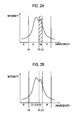
- FIGS. 2A and 2B are diagrams showing wavebands of color component light of the first embodiment.
- blue component light has a waveband shorter than a wavelength (a).
- Green component light has a waveband between the wavelength (a) and a wavelength (b).
- Yellow component light Ye has a waveband between the wavelength (b) and a wavelength (c).
- Red component light has a waveband longer than the wavelength (c).
- yellow component light Ye is cut as shown in Fig. 2A .
- the cutoff wavelength of the dichroic mirror 52 is the wavelength (c)
- yellow component light Ye is cut on a light path of green component light separated by the dichroic mirror 52.
- yellow component light Ye is not cut as shown in Fig. 2B .
- the cutoff wavelength of the dichroic mirror 52 is the wavelength (c)
- yellow component light Ye is superimposed on green component light.
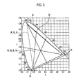
- FIG. 3 is a diagram showing a color reproduction range of the first embodiment.
- a color reproduction range (R, G, B) of light emitted from the lighting unit 120 is represented by a triangle the vertices of which are points R, G, and B.
- a color reproduction range (R, G, B, Ye) of light emitted from the lighting unit 120 is represented by a triangle the vertices of which are points R, G', and B.
- the color reproduction range of light emitted from the lighting unit 120 is basically reduced, compared to the case where yellow component light Ye is not used.
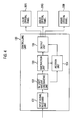
- Fig. 4 is a block diagram showing a controlling unit 130 provided to the projection display apparatus 100 of the first embodiment.
- the controlling unit 130 includes an input signal receiving unit 131, a light amount specifying unit 132, a subtraction unit 133, an addition unit 134, and an output unit 135.
- the input signal receiving unit 131 acquires a red input signal Rin, a green input signal Gin, and a blue input signal Bin.
- the input signal receiving unit 131 inputs the red input signal Rin, the green input signal Gin, and the blue input signal Bin into the light amount specifying unit 132.
- the light amount specifying unit 132 specifies a light amount of yellow component light Ye emitted from the liquid crystal panel 30G. To be more specific, the light amount specifying unit 132 specifies yellow component light Ye emitted from the liquid crystal panel 30G by multiplying a light amount (a maximum light amount) of yellow component light Ye emitted from the light source 10 and the transmittance of the liquid crystal panel 30G. Subsequently, the light amount specifying unit 132 acquires a signal (a virtual signal Ye1) corresponding to the yellow component light Ye emitted from the liquid crystal panel 30G.
- the light amount specifying unit 132 stores, in advance, characteristics of light emitted from the light source 10, and specifies the maximum light amount of yellow component light Ye, depending on power to be applied to the light source 10.
- the subtraction unit 133 performs a subtraction process on a red input signal Rin and a green input signal Gin based on the virtual signal Ye1. To be more specific, first, the subtraction unit 133 compares the virtual signal Ye1 with a minimum value (MIN(R, G)). The minimum value (MIN(R, G)) is the input signal having the lower signal intensity between the red input signal Rin and the green input signal Gin.
- the addition unit 134 performs an addition process on a blue input signal Bin, based on a subtraction result of the subtraction unit 133. To be more specific, first, the addition unit 134 compares the virtual signal Ye1 with a minimum value (MIN(R, G)).
- the output unit 135 Based on the subtraction result of the subtraction unit 133 and an addition result of the addition unit 134, the output unit 135 generates a red output signal Rout, a green output signal Gout, and a blue output signal Bout.
- the red output signal Rout, the green output signal Gout, and the blue output signal Bout are respectively the red signal R1, the green signal G1, and the blue signal B1 described above.
- FIG. 5 is a diagram for describing a method of acquiring the virtual signal Ye1 of the first embodiment.
- the transmittance of the liquid crystal panel 30G is denoted by "p," an amount (a maximum) of green component light emitted from the light source 10 by “G Lmax ,” a light amount (a maximum light amount) of yellow component light Ye emitted from the light source 10 by “Ye Lmax ,” a light amount of green component light emitted from the liquid crystal panel 30G by “G L1 ,” and a light amount of yellow component light Ye emitted from the liquid crystal panel 30G by "Ye L1 .”
- the light amount G L1 and the light amount Ye L1 are represented by Equations (7) and (8) below, respectively.
- Equation (9) a desired light amount "G L2 " of green component light emitted from the liquid crystal panel 30G is represented by Equations (9) and (10).
- Equation (9) represents a theoretical desired light amount of green component light in the case where the virtual signal Ye1 is not used.
- Equation (10) represents a practical desired light amount of green component light in the case where the virtual signal Ye1 is used.
- Equations (9) and (10) enables the derivations of the following Equations (11) and (12).
- Equations (9) and (10) enables the derivations of the following Equations (11) and (12).
- Equation (12) q ⁇ Ye Lmax ⁇ G Lmax / G Lmax + Ye Lmax
- the theoretical transmittance "q" is a given value. Further, being determined by the characteristics of light emitted from the light source 10, the maximum light amount "G Lmax " and the maximum light amount "Ye Lmax " are also given values.
- the light amount specifying unit 132 is capable of specifying the light amount "Ye L1 " on the basis of the green input signal Gin, the maximum light amount “G Lmax ,” and the maximum light amount “Ye Lmax .” Accordingly, the light amount specifying unit 132 is capable of acquiring the virtual signal Ye1 corresponding to the light amount "Ye L1 .”
- the virtual signal Ye1 is "80," and considered is a picture element in which signal values (Rin, Gin, Bin) of the red input signal Rin, the green input signal Gin, and the blue input signal Bin are (50, 100, 50).
- the red signal R 1 and the green signal G 1 are calculated using Equations (3) and (4), respectively.
- yellow component light Ye (virtual signal Ye1) emitted from the liquid crystal panel 30G is added. Accordingly, signal values (R, G, B) corresponding to respective color component light emitted from the projection display apparatus 100 are given by (80, 130, 80).
- Hues of light reproduced by signal values of red, green, and blue are calculated using Equations (21) to (23) below.
- the hue (H) of an input image signal (50, 100, 50) is calculated using Equation (22). Therefore, the hue (H) of the input image signal (50, 100, 50) is "120.”
- the hue (H) of image light (80, 130, 80) emitted from the projection display apparatus 100 is calculated using Equation (22). Specifically, the hue (H) of the image light (80, 130, 80) is "120.”
- the red input signal Rin and the green input signal Gin reduced, but also the blue input signal Bin is increased. This restrains the hue of image light emitted from the projection display apparatus 100 from not matching the hue of an input image signal.
- the virtual signal Ye1 corresponding to the smaller input signal between a red input signal Rin and a green input signal Gin is subtracted from both the red input signal Rin and the green input signal Gin.
- the red output signal Rout, the green output signal Gout, and the blue output signal Bout are as follows.
- B out 50
- signal values (R, G, B) corresponding to respective color component light emitted from the projection display apparatus 100 are (80, 130, 50).
- the hue (H) of image light emitted from the projection display apparatus 100 is calculated using Equation (22). Specifically, the hue (H) of image light (80, 130, 50) is "97.5.”
- the virtual signal Ye1 is subtracted from both the red input signal Rin and the green input signal Gin as much as possible.
- B out 50
- signal values (R, G, B) corresponding to respective color component light emitted from the projection display apparatus 100 are (80, 100, 50).
- the hue (H) of image light emitted from the projection display apparatus 100 is calculated using Equation (22). Specifically, the hue (H) of image light (80, 100, 50) is "84.”
- Fig. 6 is a diagram showing a relationship between the comparative method (the first and second examples) and the first embodiment.
- a point P 1 (50, 100, 50) corresponding to an image input signal is shifted to a point P 2 (130, 180, 50) by a superimposition of yellow component light Ye.
- a subtraction of the virtual signal Ye1 from the red input signal Rin causes the point P 2 (130, 180, 50) to be shifted to a point P 3 (80, 180, 50).
- the virtual signal Ye1 corresponding to the smaller input signal between a red input signal Rin and a green input signal Gin is subtracted from the green input signal Gin. Accordingly, the point P 3 (80, 180, 50) is shifted to a point P 4 (80, 130, 50).
- the virtual signal Ye1 is subtracted from the green input signal Gin as much as possible. Accordingly, the point P 3 (80, 180, 50) is shifted to a point P 5 (80, 100, 50) via the point P 4 (80, 130, 50).
- the virtual signal Ye1 corresponding to the smaller input signal between the red input signal Rin and the green input signal Gin is subtracted from the green input signal Gin. Then a part of the virtual signal Ye1 remained without being subtracted from the red input signal Rin and the green input signal Gin is added to the blue input signal Bin. Accordingly, the point P 3 (80, 180, 50) is shifted to a point P 6 (80, 130, 80) via the point P 4 (80, 130, 50).
- hue is considered to be a periphery (a line showing a wavelength in a monotonic color) of a chromaticity diagram from a white point WP.
- a hue corresponding to an image input signal is a vector which goes from the white point WH to a periphery (a neighborhood of 520 nm) of the chromaticity diagram via the point P 1 .
- a hue corresponding to the first example of the comparative method is a vector which goes from the white point WH to a periphery (a neighborhood of 540 nm) of the chromaticity diagram via the point P 4 .
- a hue corresponding to the second example of the comparative method is a vector which goes from the white point WH to a periphery (a neighborhood of 550 nm) of the chromaticity diagram via the point P 5 .
- a hue corresponding to the first embodiment is a vector which goes from the white point WH to a periphery (a neighborhood of 520 nm) of the chromaticity diagram via the point P 6 .
- the hue of image light emitted from the projection display apparatus 100 is prevented from not matching a hue of an input image signal, compared to the comparative method.
- the subtraction unit 133 generates a red output signal Rout and a green output signal Gout by performing subtraction processing on a red input signal Rin and a green input signal Gin, based on a light amount of yellow component light Ye (virtual signal Ye1). Therefore, the deterioration of not only color purity but also saturation can be restrained.
- the addition unit 134 generates a blue output signal Bout by performing addition processing on a blue input signal Bin, based on the subtraction result of the subtraction unit 133. Accordingly, the deterioration of color purity can be further restrained.
- an optical apparatus may be provided which selectively switches between the transmission and blocking of yellow component light Ye.
- an optical device blocking yellow component light Ye may be mechanically put on or removed from the light path of green component light.
- the light path of green component light may be provided with an optical device which transmits green component light as well as electrically switches between the transmission and blocking of yellow component light Ye.
- a light imager is not limited to the transmissive liquid crystal panel 30.
- a light imager may be a DMD (Digital Micromirror Device) or an LCOS (Liquid Crystal on Silicon).
- a cutoff wavelength of the dichroic mirror 52 is not limited to one provided between a waveband of yellow component light Ye and that of red component light.
- a cutoff wavelength of the dichroic mirror 52 may be provided between a waveband of green component light and that of yellow component light Ye.
- yellow component light Ye is superimposed on red component light. Accordingly, the virtual signal Ye1 is acquired based on the red input signal Rin, the maximum light amount "R Lmax ,” and the maximum light amount "Ye Lmax .”
- the method of acquiring the virtual signal Ye1 (light amount “Ye L1 ”) is not limited to one in which the real transmittance "p" is considered, i.e., one in which a light amount of yellow component light Ye emitted from the liquid crystal panel 30G is considered.
- the method of acquiring the virtual signal Ye1 may be one in which only the theoretical transmittance "q” and the maximum light amount "Ye Lmax " are considered.
- the method of acquiring the virtual signal Ye1 may be one in which only the maximum light amount "Ye Lmax " is considered.
- the fourth color component light is not limited to yellow component light Ye.
- the fourth color component light may be magenta component light or cyan component light.
- Magenta component light is light substitutable by red component light and blue component light.
- Cyan component light is light substitutable by green component light and blue component light.
Landscapes
- Engineering & Computer Science (AREA)
- Multimedia (AREA)
- Signal Processing (AREA)
- Projection Apparatus (AREA)
- Control Of Indicators Other Than Cathode Ray Tubes (AREA)
- Video Image Reproduction Devices For Color Tv Systems (AREA)
- Controls And Circuits For Display Device (AREA)
Applications Claiming Priority (1)
| Application Number | Priority Date | Filing Date | Title |
|---|---|---|---|
| JP2007309352A JP2009134018A (ja) | 2007-11-29 | 2007-11-29 | 映像信号変換装置及び映像表示装置 |
Publications (2)
| Publication Number | Publication Date |
|---|---|
| EP2068568A2 true EP2068568A2 (de) | 2009-06-10 |
| EP2068568A3 EP2068568A3 (de) | 2010-03-17 |
Family
ID=40379774
Family Applications (1)
| Application Number | Title | Priority Date | Filing Date |
|---|---|---|---|
| EP08020836A Withdrawn EP2068568A3 (de) | 2007-11-29 | 2008-12-01 | Bildsignalumwandlungsvorrichtung und Bildanzeigevorrichtung |
Country Status (4)
| Country | Link |
|---|---|
| US (1) | US20090141050A1 (de) |
| EP (1) | EP2068568A3 (de) |
| JP (1) | JP2009134018A (de) |
| CN (1) | CN101448165A (de) |
Citations (1)
| Publication number | Priority date | Publication date | Assignee | Title |
|---|---|---|---|---|
| JP2001186539A (ja) | 1999-10-12 | 2001-07-06 | Canon Inc | 画像処理装置及び投射型表示装置 |
Family Cites Families (9)
| Publication number | Priority date | Publication date | Assignee | Title |
|---|---|---|---|---|
| JPH08327964A (ja) * | 1995-06-02 | 1996-12-13 | Matsushita Electric Ind Co Ltd | 投写型画像表示装置 |
| US6108053A (en) * | 1997-05-30 | 2000-08-22 | Texas Instruments Incorporated | Method of calibrating a color wheel system having a clear segment |
| US7064773B1 (en) * | 1999-03-30 | 2006-06-20 | Canon Kabushiki Kaisha | Display apparatus |
| JP4489262B2 (ja) * | 2000-07-28 | 2010-06-23 | 日立プラズマディスプレイ株式会社 | カラー表示の色再現補正回路及びカラーディスプレイ |
| JP2002287247A (ja) * | 2001-03-28 | 2002-10-03 | Seiko Epson Corp | 色分離合成光学系およびプロジェクタ |
| GB2411068B (en) * | 2003-03-25 | 2005-12-07 | Hitachi Ltd | Projection type color display device |
| JP2006293095A (ja) * | 2005-04-12 | 2006-10-26 | Toshiba Matsushita Display Technology Co Ltd | 液晶表示装置、および液晶表示装置の表示方法 |
| US7911486B2 (en) * | 2006-10-30 | 2011-03-22 | Himax Display, Inc. | Method and device for images brightness control, image processing and color data generation in display devices |
| JP4286306B2 (ja) * | 2006-10-31 | 2009-06-24 | 三洋電機株式会社 | 照明装置及び投写型映像表示装置 |
-
2007
- 2007-11-29 JP JP2007309352A patent/JP2009134018A/ja not_active Ceased
-
2008
- 2008-11-27 CN CNA2008101774343A patent/CN101448165A/zh active Pending
- 2008-12-01 US US12/325,374 patent/US20090141050A1/en not_active Abandoned
- 2008-12-01 EP EP08020836A patent/EP2068568A3/de not_active Withdrawn
Patent Citations (1)
| Publication number | Priority date | Publication date | Assignee | Title |
|---|---|---|---|---|
| JP2001186539A (ja) | 1999-10-12 | 2001-07-06 | Canon Inc | 画像処理装置及び投射型表示装置 |
Also Published As
| Publication number | Publication date |
|---|---|
| US20090141050A1 (en) | 2009-06-04 |
| EP2068568A3 (de) | 2010-03-17 |
| CN101448165A (zh) | 2009-06-03 |
| JP2009134018A (ja) | 2009-06-18 |
Similar Documents
| Publication | Publication Date | Title |
|---|---|---|
| CN101583903B (zh) | 多基色led投影系统 | |
| US8246177B2 (en) | Lighting unit and projection display apparatus | |
| CN107533278B (zh) | 投影显示装置 | |
| US20090079885A1 (en) | Stereo projection optical system | |
| KR101031988B1 (ko) | 2단 프로젝터 아키텍처 | |
| JP4357553B2 (ja) | 照明装置及び投写型映像表示装置 | |
| US8123359B2 (en) | Illumination apparatus and projection display apparatus | |
| JP4781307B2 (ja) | 照明装置及び投写型映像表示装置 | |
| US7934837B2 (en) | Projection display device | |
| US20020089679A1 (en) | Color separating/synthesizing apparatus | |
| US7148936B1 (en) | Color-separation/synthesis optical system with particular cut-off wavelengths and emission-side polarizer and projection type liquid crystal display device using the same | |
| EP4007275A1 (de) | Darstellung von bildern mit grossem farbraum | |
| US20090141050A1 (en) | Image signal converting apparatus and image display apparatus | |
| JP4335664B2 (ja) | 投射型映像表示装置、背面投射型映像表示装置、光学ユニット及びスクリーンユニット | |
| KR100745242B1 (ko) | 픽셀화된 컬러 이미지들을 표시면 상에 투영하기 위한 투영 시스템 및 방법 | |
| US20060279708A1 (en) | Electronic display apparatus having adaptable color gamut | |
| Robinson et al. | Color in projection displays | |
| JP3169185B2 (ja) | 液晶プロジェクタ装置 | |
| JP2013109227A (ja) | 投写型表示装置 | |
| JP4928132B2 (ja) | 光学フィルタを有する光学系および画像投射装置 | |
| JPH05107661A (ja) | 投写型表示装置 | |
| JP2011017792A (ja) | 投射型映像表示装置 | |
| KR100763396B1 (ko) | 조명 광학계 | |
| KR100223882B1 (ko) | 엘씨디 프로젝터의 좌우 색차 보정장치 | |
| KR19980078117A (ko) | 액정 프로젝션 장치 |
Legal Events
| Date | Code | Title | Description |
|---|---|---|---|
| PUAI | Public reference made under article 153(3) epc to a published international application that has entered the european phase |
Free format text: ORIGINAL CODE: 0009012 |
|
| AK | Designated contracting states |
Kind code of ref document: A2 Designated state(s): AT BE BG CH CY CZ DE DK EE ES FI FR GB GR HR HU IE IS IT LI LT LU LV MC MT NL NO PL PT RO SE SI SK TR |
|
| AX | Request for extension of the european patent |
Extension state: AL BA MK RS |
|
| PUAL | Search report despatched |
Free format text: ORIGINAL CODE: 0009013 |
|
| AK | Designated contracting states |
Kind code of ref document: A3 Designated state(s): AT BE BG CH CY CZ DE DK EE ES FI FR GB GR HR HU IE IS IT LI LT LU LV MC MT NL NO PL PT RO SE SI SK TR |
|
| AX | Request for extension of the european patent |
Extension state: AL BA MK RS |
|
| RIC1 | Information provided on ipc code assigned before grant |
Ipc: H04N 9/68 20060101ALI20100208BHEP Ipc: H04N 9/64 20060101ALI20100208BHEP Ipc: H04N 9/31 20060101AFI20090304BHEP |
|
| 17P | Request for examination filed |
Effective date: 20100908 |
|
| 17Q | First examination report despatched |
Effective date: 20101004 |
|
| AKX | Designation fees paid |
Designated state(s): DE GB |
|
| STAA | Information on the status of an ep patent application or granted ep patent |
Free format text: STATUS: THE APPLICATION IS DEEMED TO BE WITHDRAWN |
|
| 18D | Application deemed to be withdrawn |
Effective date: 20120228 |