EP2068331B1 - Schaltgetriebeanordnung mit niedriger, mittlerer oder hoher Spannung und mit mindestens einem beweglichen Kontakt - Google Patents
Schaltgetriebeanordnung mit niedriger, mittlerer oder hoher Spannung und mit mindestens einem beweglichen Kontakt Download PDFInfo
- Publication number
- EP2068331B1 EP2068331B1 EP07023713A EP07023713A EP2068331B1 EP 2068331 B1 EP2068331 B1 EP 2068331B1 EP 07023713 A EP07023713 A EP 07023713A EP 07023713 A EP07023713 A EP 07023713A EP 2068331 B1 EP2068331 B1 EP 2068331B1
- Authority
- EP
- European Patent Office
- Prior art keywords
- voltage
- low
- medium
- connection piece
- piece
- Prior art date
- Legal status (The legal status is an assumption and is not a legal conclusion. Google has not performed a legal analysis and makes no representation as to the accuracy of the status listed.)
- Not-in-force
Links
- 239000012528 membrane Substances 0.000 claims description 12
- 239000002184 metal Substances 0.000 claims 3
- 239000004020 conductor Substances 0.000 description 5
- 238000010438 heat treatment Methods 0.000 description 3
- 238000000034 method Methods 0.000 description 3
- 238000013016 damping Methods 0.000 description 2
- 239000000463 material Substances 0.000 description 2
- 238000005457 optimization Methods 0.000 description 2
- 230000007704 transition Effects 0.000 description 2
- 238000003466 welding Methods 0.000 description 2
- 230000006835 compression Effects 0.000 description 1
- 238000007906 compression Methods 0.000 description 1
- 238000001816 cooling Methods 0.000 description 1
- 230000006837 decompression Effects 0.000 description 1
- 230000001419 dependent effect Effects 0.000 description 1
- 238000009792 diffusion process Methods 0.000 description 1
- 238000005058 metal casting Methods 0.000 description 1
- 238000003825 pressing Methods 0.000 description 1
- 238000005096 rolling process Methods 0.000 description 1
- 238000005476 soldering Methods 0.000 description 1
Images


Classifications
-
- H—ELECTRICITY
- H01—ELECTRIC ELEMENTS
- H01H—ELECTRIC SWITCHES; RELAYS; SELECTORS; EMERGENCY PROTECTIVE DEVICES
- H01H1/00—Contacts
- H01H1/58—Electric connections to or between contacts; Terminals
- H01H1/5822—Flexible connections between movable contact and terminal
-
- H—ELECTRICITY
- H01—ELECTRIC ELEMENTS
- H01H—ELECTRIC SWITCHES; RELAYS; SELECTORS; EMERGENCY PROTECTIVE DEVICES
- H01H33/00—High-tension or heavy-current switches with arc-extinguishing or arc-preventing means
- H01H33/60—Switches wherein the means for extinguishing or preventing the arc do not include separate means for obtaining or increasing flow of arc-extinguishing fluid
- H01H33/66—Vacuum switches
- H01H33/6606—Terminal arrangements
- H01H2033/6613—Cooling arrangements directly associated with the terminal arrangements
-
- H—ELECTRICITY
- H01—ELECTRIC ELEMENTS
- H01H—ELECTRIC SWITCHES; RELAYS; SELECTORS; EMERGENCY PROTECTIVE DEVICES
- H01H33/00—High-tension or heavy-current switches with arc-extinguishing or arc-preventing means
- H01H33/02—Details
- H01H33/025—Terminal arrangements
-
- H—ELECTRICITY
- H01—ELECTRIC ELEMENTS
- H01H—ELECTRIC SWITCHES; RELAYS; SELECTORS; EMERGENCY PROTECTIVE DEVICES
- H01H33/00—High-tension or heavy-current switches with arc-extinguishing or arc-preventing means
- H01H33/60—Switches wherein the means for extinguishing or preventing the arc do not include separate means for obtaining or increasing flow of arc-extinguishing fluid
- H01H33/66—Vacuum switches
- H01H33/6606—Terminal arrangements
Definitions
- the invention relates to a low-voltage, medium-voltage or high-voltage switchgear assembly with at least one moveable contact piece, in which the moveable contact is connected to a stationary connection piece electrically with a flexible connecting means, in accordance with the preamble of patent claim 1.
- the technical field relates to switching devices, in particular for the medium-voltage range. These switching devices are equipped with so-called pole parts, in which vacuum interrupter chambers are installed or cast in as actual switching elements.
- the pole parts have two stationary connection pieces, to which the switching device in the switchgear assembly is connected to further components.
- the stationary connection pieces are connected to the feed lines of the vacuum interrupter chamber within the pole part.
- This connection can be designed to be rigid on one side, the fixed contact side.
- the stationary connection piece of the pole part needs to be connected to the moveable feed line of the vacuum interrupter chamber in such a way that a relative movement of the moveable feed line is made possible.
- This technical object is generally achieved by a rolling contact, a multicontact system or a connector strip.
- Connector strips are usually in the form of separate component parts, which also need to be fitted separately.
- DE 9017054 U1 has disclosed a switch pole arrangement with a moveable connector strip.
- This document describes an arrangement of an open pole part, in which a vacuum interrupter chamber is installed in the tubular pole part via corresponding mounts.
- the moveable feed line is connected to the connection piece of the pole part, in this case in the form of a busbar, by means of a connector strip.
- the fixing of the connector strip in this case takes place by means of screws.
- Ring-type connector strips are also known.
- the solution which has until now mainly been used of connecting the connector strip to the connection piece of the pole part by means of screw connections has the disadvantage that the connecting point has a relatively high electrical transfer resistance. This is brought about by the only partial surface contact of the connector strip and the connection piece in the region of the screw connection. Furthermore, the screwed connecting point also has the disadvantage of a relatively high thermal resistance. Since the thermal energy which arises in the pole part is principally dissipated via the connection pieces and the conductors connected thereto, the screw connection not only results in an increase in the thermal energy produced but also in a reduction in the thermal conduction and therefore overall in greater heating of the pole part.
- the invention is therefore based on the object of producing a connection between the connector strip and the connection piece of the pole part which has an electrical and thermal resistance which is as low as possible whilst maintaining the mechanical properties of a conventional connector strip solution.
- the present invention describes the optimization of the so-called connector strip solution.
- the essence of the invention is in this case the fact that the flexible connecting means is connected to the connection piece directly or with an intermediate piece, which can be connected to the connection piece, cohesively or at least unreleasably.
- the arrangement according to the invention is distinguished from known designs from the prior art.
- the connector strip i.e. the connecting means between the contact piece feed line and the connection piece
- the connector strip is a separate component part, which not only needs to be fitted to the contact piece feed line of the contact piece, but also additionally needs to be fitted to the connection piece.
- Releasable connections produce transfer resistances, however. As a result of the high potential current levels, a notably high power is released via the transfer resistances, and this results in a heat flow from the conductors.
- connection piece is intended to mean that connection piece which runs through the pole part wall for an external contact to the outside.
- the connecting point may be a cohesive, in a particular case even a materially cohesive, transition between the connection piece and the connector strip.
- connection piece or on the intermediate piece in such a way that it forms, with the connection piece or the intermediate piece, an integral unit. This is the optimum form which provides the least transfer resistance.
- connection piece and the connecting means i.e. the connector strip, for example, is a pressed or cast connection.
- connection piece is a hollow-cylindrical metallic component part, in which the hollow cylinder is parallel to the contact piece actuation axis and at least one connecting means is arranged within the hollow cylinder and is connected to the hollow cylinder section integrally and materially cohesively or in pressed fashion.
- a further configuration consists in the fact that two connector strips are arranged on diametrically opposite sides and can be attached centrally one above the other to the contact piece feed line of the moveable contact piece.
- connector strips are designed to be flexible.
- a further configuration consists in the fact that the connector strips can be fitted in such a way that they are bent forwards in one direction. In this case, even greater flexibility in the mechanical actuation excursion is made possible.
- a special but likewise effective and advantageous configuration consists in the fact that four connector strips, in each case two diametrically positioned connector strips, are each arranged in such a way that they are bent forwards in one direction.
- a specific embodiment is that a type of sheet membrane is provided as the connecting means, which sheet membrane is connected centrally with screw means on the moveable contact pin and at the edge to the hollow-cylindrical section of the connection piece.
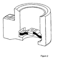
- Figure 1 shows a first embodiment.
- the connector strip cohesively to the connection piece.
- one end of the connector strip is intended to be pressed or cast directly with the connection piece during warm-pressing or metal-casting of the connection piece.
- the total resistance electrical and thermal
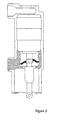
- Figure 2 shows a second embodiment, in which, in addition to the simple embodiment with a single connector strip, a multiple embodiment is also proposed, in which a plurality of connector strips are cohesively connected to an approximately hollow-cylindrical connection piece.
- the connector strips care should be taken to ensure that the electrical resistances of the various electrical paths are virtually equal, so that the current is split uniformly. This can take place by the cross sections of the flexible conductors or of subregions of the connection piece being adjusted.
- Figure 3 shows the side view of the installed state of the embodiment with respect to figure 2 .
- the pressed or fused-in connector strips are standard connector strips which are used in this form in the prior art.
- the connection to the vacuum interrupter chamber then takes place via the existing drilled-through holes in the end faces of the connector strips by means of a pushed-through connection.
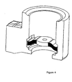
- Figure 4 shows a further design embodiment, namely using a special connector strip, in which two or more flexible conductors are connected in the center to form a common plate.
- the connection can in this case take place by means of various, known methods, such as welding, diffusion welding or soldering.
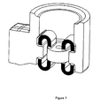
- Figure 6 shows a development of this concept in which, in one step, individual connector strips are cohesively connected to the outer and one inner connection piece.
- the position and the number of the flexible connections used can be selected very differently; a few embodiments are already illustrated in figures 5 and 7 .
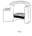
- Figure 8 shows a further embodiment of the basic concept in which the use of a sheet membrane or corrugated washer, which is, with a round embodiment, attached to the entire inner circumference of the connection piece or is connected thereto in an interlocking manner, is also proposed.
Landscapes
- Physics & Mathematics (AREA)
- Electromagnetism (AREA)
- Thermally Actuated Switches (AREA)
- Gas-Insulated Switchgears (AREA)
- Braking Arrangements (AREA)
- Current-Collector Devices For Electrically Propelled Vehicles (AREA)
- Connections Effected By Soldering, Adhesion, Or Permanent Deformation (AREA)
- Connector Housings Or Holding Contact Members (AREA)
Claims (9)
- Nieder-, Mittel- oder Hochspannungsschaltanlage mit mindestens einem beweglichen Kontaktstück, bei welchem das bewegliche Kontaktstück mit einem flexiblen Verbindungsmittel elektrisch mit einem Anschlussstück verbunden ist, wobei das flexible Verbindungsmittel mit dem Anschlussstück direkt oder mit einem mit dem Anschlussstück verbundenen zwischenstück stoffschlüssig oder zumindest unlösbar verbunden ist, dadurch gekennzeichnet, dass das Anschlussstück ein hohlzylindrisches, metallisches Bauteil ist, bei welchem der Hohlzylinder parallel zur Kontaktbetätigungsachse liegt, und innerhalb des Hohlzylinders mindestens ein Verbindungsmittel angeordnet ist, welches mit dem Hohlzylinderabschnitt einstückig und materialschlüssig oder verpresst verbunden ist.
- Nieder-, Mittel- oder Hochspannungsschaltanlage nach Anspruch 1,
wobei
das Verbindungsmittel einstückig materialschlüssig am Anschlussstück oder am Zwischenstück angeformt ist, derart, dass dies mit dem Anschlussstück oder dem Zwischenstück eine einstückige Einheit bildet. - Nieder-, Mittel- oder Hochspannungsschaltanlage nach Anspruch 1,
wobei
die Verbindungsstelle zwischen dem Anschlussstück und dem Verbindungsmittel eine verpresste oder vergossene Verbindung ist. - Nieder-, Mittel- oder Nochspannungsschaltanlage nach Anspruch 1,
wobei
als Verbindungsmittel zwei Verbindungsbänder an diametral gegenüberliegenden Seiten angeordnet sind und mittig übereinander an der Kontaktstückzuleitung des beweglichen Kontaktes anbringbar sind. - Nieder-, Mittel- oder Hochspannungsschaltanlage nach Anspruch 4,
wobei
die Verbindungsbänder flexibel ausgestaltet sind. - Nieder-, Mittel- oder Hochspannungsschaltanlage nach Anspruch 5,
wobei
die Verbindungsbänder so angebracht sind, dass sie in einer Richtung vorgebogen sind. - Nieder-, Mittel- oder Hochspannungsschaltanlage nach Anspruch 6,
wobei
4 Verbindungsbänder, jeweils zwei diametral liegende Verbindungsbänder, jeweils so angeordnet sind, dass sie in einer Richtung vorgebogen sind. - Nieder-, Mittel- oder Hochspannungsschaltanlage nach Anspruch 1,
wobei
als Verbindungsmittel eine Art Metallblechmembran vorgesehen ist, welche zentral mit Verschraubungsmitteln an der beweglichen Kontaktstückzuleitung und am Rand mit dem
hohlzylindrischen Abschnitt des Anschlussstücks verbunden ist. - Nieder-, Mittel- oder Hochspannungsschaltanlage nach Anspruch 8,
wobei
die Metallblechmembran eine konzentrisch gewellte Membran ist.
Priority Applications (7)
| Application Number | Priority Date | Filing Date | Title |
|---|---|---|---|
| EP07023713A EP2068331B1 (de) | 2007-12-07 | 2007-12-07 | Schaltgetriebeanordnung mit niedriger, mittlerer oder hoher Spannung und mit mindestens einem beweglichen Kontakt |
| DE602007013785T DE602007013785D1 (de) | 2007-12-07 | 2007-12-07 | Schaltgetriebeanordnung mit niedriger, mittlerer oder hoher Spannung und mit mindestens einem beweglichen Kontakt |
| AT07023713T ATE504931T1 (de) | 2007-12-07 | 2007-12-07 | Schaltgetriebeanordnung mit niedriger, mittlerer oder hoher spannung und mit mindestens einem beweglichen kontakt |
| EP08855853A EP2240945A1 (de) | 2007-12-07 | 2008-12-04 | Niederspannungs-, mittelspannungs- oder hochspannungsschaltbaugruppe mit mindestens einem beweglichen kontakt |
| PCT/EP2008/010260 WO2009071287A1 (en) | 2007-12-07 | 2008-12-04 | Low-voltage, medium-voltage or high-voltage switchgear assembly with at least one moveable contact |
| CN200880119719XA CN101889322A (zh) | 2007-12-07 | 2008-12-04 | 具有至少一个可移动接触件的低压、中压或高压开关组件 |
| US12/795,093 US20100300852A1 (en) | 2007-12-07 | 2010-06-07 | Low-voltage, medium-voltage or high-voltage switchgear assembly with at least one moveable contact |
Applications Claiming Priority (1)
| Application Number | Priority Date | Filing Date | Title |
|---|---|---|---|
| EP07023713A EP2068331B1 (de) | 2007-12-07 | 2007-12-07 | Schaltgetriebeanordnung mit niedriger, mittlerer oder hoher Spannung und mit mindestens einem beweglichen Kontakt |
Publications (2)
| Publication Number | Publication Date |
|---|---|
| EP2068331A1 EP2068331A1 (de) | 2009-06-10 |
| EP2068331B1 true EP2068331B1 (de) | 2011-04-06 |
Family
ID=39363857
Family Applications (2)
| Application Number | Title | Priority Date | Filing Date |
|---|---|---|---|
| EP07023713A Not-in-force EP2068331B1 (de) | 2007-12-07 | 2007-12-07 | Schaltgetriebeanordnung mit niedriger, mittlerer oder hoher Spannung und mit mindestens einem beweglichen Kontakt |
| EP08855853A Withdrawn EP2240945A1 (de) | 2007-12-07 | 2008-12-04 | Niederspannungs-, mittelspannungs- oder hochspannungsschaltbaugruppe mit mindestens einem beweglichen kontakt |
Family Applications After (1)
| Application Number | Title | Priority Date | Filing Date |
|---|---|---|---|
| EP08855853A Withdrawn EP2240945A1 (de) | 2007-12-07 | 2008-12-04 | Niederspannungs-, mittelspannungs- oder hochspannungsschaltbaugruppe mit mindestens einem beweglichen kontakt |
Country Status (6)
| Country | Link |
|---|---|
| US (1) | US20100300852A1 (de) |
| EP (2) | EP2068331B1 (de) |
| CN (1) | CN101889322A (de) |
| AT (1) | ATE504931T1 (de) |
| DE (1) | DE602007013785D1 (de) |
| WO (1) | WO2009071287A1 (de) |
Families Citing this family (5)
| Publication number | Priority date | Publication date | Assignee | Title |
|---|---|---|---|---|
| USD658133S1 (en) * | 2009-10-15 | 2012-04-24 | Abb Technology Ag | Switch |
| USD658589S1 (en) * | 2009-10-23 | 2012-05-01 | Abb Technology Ag | Switch |
| USD660253S1 (en) * | 2010-04-28 | 2012-05-22 | Abb Technology Ag | Pole part |
| USD651181S1 (en) * | 2010-08-25 | 2011-12-27 | Wika Alexander Wiegand Se & Co. Kg | Pressure switch |
| CN105655193B (zh) * | 2016-01-28 | 2017-11-14 | 国网江苏省电力公司泰兴市供电公司 | 一种真空断路器 |
Family Cites Families (7)
| Publication number | Priority date | Publication date | Assignee | Title |
|---|---|---|---|---|
| US3393389A (en) * | 1960-06-06 | 1968-07-16 | Texas Instruments Inc | Adjustable bridging contact member type thermostatic switch |
| DE19636237A1 (de) * | 1996-06-21 | 1998-01-02 | Siemens Ag | Schaltkontaktsystem eines Niederspannungs-Leistungsschalters mit biegsamen Leitern |
| DE19712182A1 (de) * | 1997-03-22 | 1998-09-24 | Abb Patent Gmbh | Vakuumkammer |
| DE19902836A1 (de) * | 1999-01-20 | 2000-07-27 | Siemens Ag | Verfahren zur Verbindung eines Kontaktkörpers und eines flexiblen Leiters sowie Preßform zur Durchführung des Verfahrens |
| US6444939B1 (en) * | 2000-05-09 | 2002-09-03 | Eaton Corporation | Vacuum switch operating mechanism including laminated flexible shunt connector |
| DE202006007973U1 (de) * | 2006-05-10 | 2006-08-03 | Siemens Ag | Leistungsschalter, insbesondere Hochstromschalter |
| US20080189937A1 (en) * | 2007-02-08 | 2008-08-14 | Singatron Enterprise Co., Ltd. | Method of making a connector with an injection-molding technique |
-
2007
- 2007-12-07 EP EP07023713A patent/EP2068331B1/de not_active Not-in-force
- 2007-12-07 AT AT07023713T patent/ATE504931T1/de not_active IP Right Cessation
- 2007-12-07 DE DE602007013785T patent/DE602007013785D1/de active Active
-
2008
- 2008-12-04 CN CN200880119719XA patent/CN101889322A/zh active Pending
- 2008-12-04 WO PCT/EP2008/010260 patent/WO2009071287A1/en not_active Ceased
- 2008-12-04 EP EP08855853A patent/EP2240945A1/de not_active Withdrawn
-
2010
- 2010-06-07 US US12/795,093 patent/US20100300852A1/en not_active Abandoned
Also Published As
| Publication number | Publication date |
|---|---|
| EP2240945A1 (de) | 2010-10-20 |
| US20100300852A1 (en) | 2010-12-02 |
| EP2068331A1 (de) | 2009-06-10 |
| CN101889322A (zh) | 2010-11-17 |
| WO2009071287A1 (en) | 2009-06-11 |
| ATE504931T1 (de) | 2011-04-15 |
| DE602007013785D1 (de) | 2011-05-19 |
Similar Documents
| Publication | Publication Date | Title |
|---|---|---|
| JP4405265B2 (ja) | 開閉用接触子付き真空バルブ | |
| KR100996791B1 (ko) | 진공차단기의 주회로 단자 어셈블리 | |
| CN102339694B (zh) | 小型塑料外壳式断路器 | |
| EP2068331B1 (de) | Schaltgetriebeanordnung mit niedriger, mittlerer oder hoher Spannung und mit mindestens einem beweglichen Kontakt | |
| US8164402B2 (en) | Current transformer, protection device including such transformer and related circuit breaker | |
| US6444939B1 (en) | Vacuum switch operating mechanism including laminated flexible shunt connector | |
| CN101393815B (zh) | 高压功率开关的合闸电阻 | |
| JP2015527720A (ja) | 接点アセンブリ及びそれを備えた真空スイッチ | |
| KR100625225B1 (ko) | 개폐 장치 | |
| CN111952111B (zh) | 一种双断口快速真空灭弧室 | |
| CN201773802U (zh) | 小型塑料外壳式断路器 | |
| EP2747113B1 (de) | Polteil eines Schutzschalters mit einem flexiblen Leiter zum Verbinden eines bewegbaren elektrischen Kontakts | |
| GB2210204A (en) | Vacuum circuit interrupter with axial magnetic arc transfer mechanism | |
| CN101409176B (zh) | 一种真空断路器用主回路结构 | |
| EP2306482B1 (de) | Netzstromendgerätanordnung für einen Vakuumschutzschalter | |
| CN216818194U (zh) | 一种断路器结构 | |
| CN217719433U (zh) | 一种充气柜用真空断路器极柱 | |
| CN215266071U (zh) | 一种用于真空断路器的动端软连接结构 | |
| CN207116240U (zh) | 一种适用于高压设备大电流开关触头 | |
| IT1314039B1 (it) | Polo elettrico per interruttore di potenza di bassa tensione. | |
| US20240355556A1 (en) | Switchable contacting device with cooling functionality | |
| CN114203479B (zh) | 一种断路器结构 | |
| CN219040332U (zh) | 一种新型大电流断路器主回路结构装置 | |
| EP2549500A1 (de) | Gasisolierte Schaltanlage, insbesondere SF6-isolierte Schalttafeln oder Schaltpulte | |
| WO2023100303A1 (ja) | 回路遮断器 |
Legal Events
| Date | Code | Title | Description |
|---|---|---|---|
| PUAI | Public reference made under article 153(3) epc to a published international application that has entered the european phase |
Free format text: ORIGINAL CODE: 0009012 |
|
| AK | Designated contracting states |
Kind code of ref document: A1 Designated state(s): AT BE BG CH CY CZ DE DK EE ES FI FR GB GR HU IE IS IT LI LT LU LV MC MT NL PL PT RO SE SI SK TR |
|
| AX | Request for extension of the european patent |
Extension state: AL BA HR MK RS |
|
| 17P | Request for examination filed |
Effective date: 20091210 |
|
| AKX | Designation fees paid |
Designated state(s): AT BE BG CH CY CZ DE DK EE ES FI FR GB GR HU IE IS IT LI LT LU LV MC MT NL PL PT RO SE SI SK TR |
|
| 17Q | First examination report despatched |
Effective date: 20100127 |
|
| GRAP | Despatch of communication of intention to grant a patent |
Free format text: ORIGINAL CODE: EPIDOSNIGR1 |
|
| RIN1 | Information on inventor provided before grant (corrected) |
Inventor name: RUEMENAPP, TILL DR.-ING. Inventor name: HUMPERT, CHRISTOF, DR. -ING. Inventor name: GENTSCH, DIETMAR DR.-ING. |
|
| GRAS | Grant fee paid |
Free format text: ORIGINAL CODE: EPIDOSNIGR3 |
|
| GRAA | (expected) grant |
Free format text: ORIGINAL CODE: 0009210 |
|
| AK | Designated contracting states |
Kind code of ref document: B1 Designated state(s): AT BE BG CH CY CZ DE DK EE ES FI FR GB GR HU IE IS IT LI LT LU LV MC MT NL PL PT RO SE SI SK TR |
|
| REG | Reference to a national code |
Ref country code: GB Ref legal event code: FG4D |
|
| REG | Reference to a national code |
Ref country code: CH Ref legal event code: EP |
|
| REG | Reference to a national code |
Ref country code: IE Ref legal event code: FG4D |
|
| REF | Corresponds to: |
Ref document number: 602007013785 Country of ref document: DE Date of ref document: 20110519 Kind code of ref document: P |
|
| REG | Reference to a national code |
Ref country code: DE Ref legal event code: R096 Ref document number: 602007013785 Country of ref document: DE Effective date: 20110519 |
|
| REG | Reference to a national code |
Ref country code: NL Ref legal event code: T3 |
|
| PG25 | Lapsed in a contracting state [announced via postgrant information from national office to epo] |
Ref country code: SI Free format text: LAPSE BECAUSE OF FAILURE TO SUBMIT A TRANSLATION OF THE DESCRIPTION OR TO PAY THE FEE WITHIN THE PRESCRIBED TIME-LIMIT Effective date: 20110406 |
|
| LTIE | Lt: invalidation of european patent or patent extension |
Effective date: 20110406 |
|
| PG25 | Lapsed in a contracting state [announced via postgrant information from national office to epo] |
Ref country code: LT Free format text: LAPSE BECAUSE OF FAILURE TO SUBMIT A TRANSLATION OF THE DESCRIPTION OR TO PAY THE FEE WITHIN THE PRESCRIBED TIME-LIMIT Effective date: 20110406 Ref country code: PT Free format text: LAPSE BECAUSE OF FAILURE TO SUBMIT A TRANSLATION OF THE DESCRIPTION OR TO PAY THE FEE WITHIN THE PRESCRIBED TIME-LIMIT Effective date: 20110808 Ref country code: SE Free format text: LAPSE BECAUSE OF FAILURE TO SUBMIT A TRANSLATION OF THE DESCRIPTION OR TO PAY THE FEE WITHIN THE PRESCRIBED TIME-LIMIT Effective date: 20110406 |
|
| PG25 | Lapsed in a contracting state [announced via postgrant information from national office to epo] |
Ref country code: CY Free format text: LAPSE BECAUSE OF FAILURE TO SUBMIT A TRANSLATION OF THE DESCRIPTION OR TO PAY THE FEE WITHIN THE PRESCRIBED TIME-LIMIT Effective date: 20110406 Ref country code: IS Free format text: LAPSE BECAUSE OF FAILURE TO SUBMIT A TRANSLATION OF THE DESCRIPTION OR TO PAY THE FEE WITHIN THE PRESCRIBED TIME-LIMIT Effective date: 20110806 Ref country code: ES Free format text: LAPSE BECAUSE OF FAILURE TO SUBMIT A TRANSLATION OF THE DESCRIPTION OR TO PAY THE FEE WITHIN THE PRESCRIBED TIME-LIMIT Effective date: 20110717 Ref country code: BE Free format text: LAPSE BECAUSE OF FAILURE TO SUBMIT A TRANSLATION OF THE DESCRIPTION OR TO PAY THE FEE WITHIN THE PRESCRIBED TIME-LIMIT Effective date: 20110406 Ref country code: LV Free format text: LAPSE BECAUSE OF FAILURE TO SUBMIT A TRANSLATION OF THE DESCRIPTION OR TO PAY THE FEE WITHIN THE PRESCRIBED TIME-LIMIT Effective date: 20110406 Ref country code: GR Free format text: LAPSE BECAUSE OF FAILURE TO SUBMIT A TRANSLATION OF THE DESCRIPTION OR TO PAY THE FEE WITHIN THE PRESCRIBED TIME-LIMIT Effective date: 20110707 Ref country code: AT Free format text: LAPSE BECAUSE OF FAILURE TO SUBMIT A TRANSLATION OF THE DESCRIPTION OR TO PAY THE FEE WITHIN THE PRESCRIBED TIME-LIMIT Effective date: 20110406 Ref country code: FI Free format text: LAPSE BECAUSE OF FAILURE TO SUBMIT A TRANSLATION OF THE DESCRIPTION OR TO PAY THE FEE WITHIN THE PRESCRIBED TIME-LIMIT Effective date: 20110406 |
|
| PG25 | Lapsed in a contracting state [announced via postgrant information from national office to epo] |
Ref country code: EE Free format text: LAPSE BECAUSE OF FAILURE TO SUBMIT A TRANSLATION OF THE DESCRIPTION OR TO PAY THE FEE WITHIN THE PRESCRIBED TIME-LIMIT Effective date: 20110406 |
|
| PGFP | Annual fee paid to national office [announced via postgrant information from national office to epo] |
Ref country code: FR Payment date: 20120105 Year of fee payment: 5 Ref country code: NL Payment date: 20111228 Year of fee payment: 5 |
|
| PLBE | No opposition filed within time limit |
Free format text: ORIGINAL CODE: 0009261 |
|
| STAA | Information on the status of an ep patent application or granted ep patent |
Free format text: STATUS: NO OPPOSITION FILED WITHIN TIME LIMIT |
|
| PG25 | Lapsed in a contracting state [announced via postgrant information from national office to epo] |
Ref country code: DK Free format text: LAPSE BECAUSE OF FAILURE TO SUBMIT A TRANSLATION OF THE DESCRIPTION OR TO PAY THE FEE WITHIN THE PRESCRIBED TIME-LIMIT Effective date: 20110406 Ref country code: SK Free format text: LAPSE BECAUSE OF FAILURE TO SUBMIT A TRANSLATION OF THE DESCRIPTION OR TO PAY THE FEE WITHIN THE PRESCRIBED TIME-LIMIT Effective date: 20110406 Ref country code: RO Free format text: LAPSE BECAUSE OF FAILURE TO SUBMIT A TRANSLATION OF THE DESCRIPTION OR TO PAY THE FEE WITHIN THE PRESCRIBED TIME-LIMIT Effective date: 20110406 Ref country code: PL Free format text: LAPSE BECAUSE OF FAILURE TO SUBMIT A TRANSLATION OF THE DESCRIPTION OR TO PAY THE FEE WITHIN THE PRESCRIBED TIME-LIMIT Effective date: 20110406 |
|
| 26N | No opposition filed |
Effective date: 20120110 |
|
| REG | Reference to a national code |
Ref country code: DE Ref legal event code: R097 Ref document number: 602007013785 Country of ref document: DE Effective date: 20120110 |
|
| PGFP | Annual fee paid to national office [announced via postgrant information from national office to epo] |
Ref country code: DE Payment date: 20111222 Year of fee payment: 5 |
|
| PGFP | Annual fee paid to national office [announced via postgrant information from national office to epo] |
Ref country code: IT Payment date: 20111222 Year of fee payment: 5 |
|
| PG25 | Lapsed in a contracting state [announced via postgrant information from national office to epo] |
Ref country code: MC Free format text: LAPSE BECAUSE OF NON-PAYMENT OF DUE FEES Effective date: 20111231 |
|
| REG | Reference to a national code |
Ref country code: CH Ref legal event code: PL |
|
| GBPC | Gb: european patent ceased through non-payment of renewal fee |
Effective date: 20111207 |
|
| REG | Reference to a national code |
Ref country code: IE Ref legal event code: MM4A |
|
| PG25 | Lapsed in a contracting state [announced via postgrant information from national office to epo] |
Ref country code: GB Free format text: LAPSE BECAUSE OF NON-PAYMENT OF DUE FEES Effective date: 20111207 Ref country code: LI Free format text: LAPSE BECAUSE OF NON-PAYMENT OF DUE FEES Effective date: 20111231 Ref country code: CH Free format text: LAPSE BECAUSE OF NON-PAYMENT OF DUE FEES Effective date: 20111231 Ref country code: IE Free format text: LAPSE BECAUSE OF NON-PAYMENT OF DUE FEES Effective date: 20111207 |
|
| PGFP | Annual fee paid to national office [announced via postgrant information from national office to epo] |
Ref country code: CZ Payment date: 20121130 Year of fee payment: 6 |
|
| PG25 | Lapsed in a contracting state [announced via postgrant information from national office to epo] |
Ref country code: MT Free format text: LAPSE BECAUSE OF FAILURE TO SUBMIT A TRANSLATION OF THE DESCRIPTION OR TO PAY THE FEE WITHIN THE PRESCRIBED TIME-LIMIT Effective date: 20110406 |
|
| PG25 | Lapsed in a contracting state [announced via postgrant information from national office to epo] |
Ref country code: LU Free format text: LAPSE BECAUSE OF NON-PAYMENT OF DUE FEES Effective date: 20111207 |
|
| PG25 | Lapsed in a contracting state [announced via postgrant information from national office to epo] |
Ref country code: BG Free format text: LAPSE BECAUSE OF FAILURE TO SUBMIT A TRANSLATION OF THE DESCRIPTION OR TO PAY THE FEE WITHIN THE PRESCRIBED TIME-LIMIT Effective date: 20110706 |
|
| REG | Reference to a national code |
Ref country code: NL Ref legal event code: V1 Effective date: 20130701 |
|
| REG | Reference to a national code |
Ref country code: FR Ref legal event code: ST Effective date: 20130830 |
|
| PG25 | Lapsed in a contracting state [announced via postgrant information from national office to epo] |
Ref country code: TR Free format text: LAPSE BECAUSE OF FAILURE TO SUBMIT A TRANSLATION OF THE DESCRIPTION OR TO PAY THE FEE WITHIN THE PRESCRIBED TIME-LIMIT Effective date: 20110406 |
|
| REG | Reference to a national code |
Ref country code: DE Ref legal event code: R119 Ref document number: 602007013785 Country of ref document: DE Effective date: 20130702 |
|
| PG25 | Lapsed in a contracting state [announced via postgrant information from national office to epo] |
Ref country code: DE Free format text: LAPSE BECAUSE OF NON-PAYMENT OF DUE FEES Effective date: 20130702 Ref country code: NL Free format text: LAPSE BECAUSE OF NON-PAYMENT OF DUE FEES Effective date: 20130701 Ref country code: HU Free format text: LAPSE BECAUSE OF FAILURE TO SUBMIT A TRANSLATION OF THE DESCRIPTION OR TO PAY THE FEE WITHIN THE PRESCRIBED TIME-LIMIT Effective date: 20110406 |
|
| PG25 | Lapsed in a contracting state [announced via postgrant information from national office to epo] |
Ref country code: FR Free format text: LAPSE BECAUSE OF NON-PAYMENT OF DUE FEES Effective date: 20130102 |
|
| PG25 | Lapsed in a contracting state [announced via postgrant information from national office to epo] |
Ref country code: IT Free format text: LAPSE BECAUSE OF NON-PAYMENT OF DUE FEES Effective date: 20121207 |
|
| PG25 | Lapsed in a contracting state [announced via postgrant information from national office to epo] |
Ref country code: CZ Free format text: LAPSE BECAUSE OF NON-PAYMENT OF DUE FEES Effective date: 20131207 |